Abstract
This paper systematically analyzes the challenges of stabilizing tunnel excavations in zones with low overburden in urban environments, through an engineering-validated case study of the Kobilja Glava Tunnel. A combined approach involving the New Austrian Tunneling Method (NATM) and the pre-installation of steel pipe umbrellas was applied as the primary pre-support measure under complex geotechnical conditions. The design, drilling, grouting, and formation of the temporary support arch were thoroughly documented, along with the implementation of shotcrete, lattice girders, self-drilling anchors, and reinforcement meshes. A numerical analysis was performed using the PLAXIS 2D software package, encompassing the modeling of deformations, shear forces, axial forces, and bending moments, with precisely defined support parameters. Geodetic monitoring recorded maximum surface settlements of up to 70 mm at an overburden of less than 3 m, while deformations were reduced to 28 mm at an overburden of 20 m. The numerical model confirmed soil plasticization within a 3 m wide zone, with maximum displacements reaching 6.3 cm, consistent with field measurements. Calculated tensile strain and angular distortion were classified according to established building damage criteria, confirming minimal structural impact on adjacent buildings. The applied combination of the NATM and the pipe umbrella pre-support system proved to be an effective and reliable solution for controlling deformations and ensuring excavation stability under conditions of limited rock cover and dense urban development. The obtained results provide a verified framework and practical recommendations for future tunneling projects in similar geotechnical and urban conditions, aiming to enhance safety, stability, and cost-effectiveness.
1. Introduction
The rapid urban growth in modern times has increased the demand for the efficient utilization of underground spaces [1]. Tunnel construction is a complex and interdisciplinary process [2]. Modern tunnel design and construction require the use of appropriate techniques and technologies at all stages of execution [3]. Tunnel excavation is considered the most critical phase due to its potential consequences [4]. The construction of road tunnels ranks among the most demanding engineering tasks, requiring careful planning, advanced excavation methods, and the application of cutting-edge technological solutions to ensure structural stability and safety [5].
Tunnel excavation under shallow overburden conditions inherently induces surface settlement, particularly when conducted in soft soil strata or geologically unfavorable rock masses. Such settlements become critical when tunnels are constructed in densely populated urban environments, directly beneath residential buildings [6,7,8,9]. The support measures applied during excavation play a key role in controlling deformations and increasing the safety of tunnel works. Properly selected methods significantly contribute to the stability of underground structures [1,10]. Excavation methods such as open-cut excavations in combination with quasi-rectangular jacking boxes showed good adaptability to complex surrounding environments, providing the good ground control in soft working environments needed for excavation [11]. Implementation of the pipe umbrella method as a pre-support system in the construction of shallow tunnels contributes to the control of the subsidence and groundwater barrier, ensuring safe excavation underneath. It is important to control pipe installation deviations and to appropriately design spacing between the pipes of a sufficient diameter [12]. Knowledge transfer from different mining and tunneling projects is of great importance for guiding engineers both in the design and construction phases. It contributes to the appropriate selection of the excavation method, pre-support and support constructions, monitoring techniques, prediction models for measurable parameters during excavation, etc. [13,14,15,16].
This paper provides an overview of the support measures implemented during the excavation of the left tunnel tube in the low overburden section (chainage 4 + 132 to 4 + 043), as part of the construction of the Kobilja Glava Tunnel—a segment of the First Transversal, a strategic road connecting the center of Sarajevo with Vogošća, intended to alleviate city traffic congestion. Located in a densely populated urban zone with approximately 500 residential buildings, this twin-tube tunnel passes through the hill of the same name, facing complex geotechnical challenges due to the extremely shallow overburden above the structure [17]. The total length of the right tunnel tube is approximately 635 m, while the left tube is about 639 m.
Tunnel construction in urban areas, especially in close proximity to residential and infrastructure facilities, requires careful planning and strict control to prevent unwanted ground settlements and damage to nearby structures [18]. Any excavation in rock that creates a void disturbs the initial stress state of the rock mass, causing a redistribution of forces and the development of a secondary stress field around the tunnel gallery [19]. These changes lead to the propagation of deformations beyond the immediate excavation area, potentially causing displacements and stresses in surrounding structures. Depending on the geotechnical characteristics of the rock mass, such effects can compromise the stability of adjacent buildings, making the timely and adequate application of support measures crucial for the safety of the entire system [20]. The geographical location of the Kobilja Glava Tunnel on the Sarajevo–Vogošća route is shown in Figure 1. The coordinates (WGS84) of the western tunnel portals area are 43.886089 N and 18.383092 E.
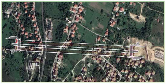
Figure 1.
Geographic location of the Kobilja Glava Tunnel on the Sarajevo–Vogošća route.
2. Engineering–Geological Characteristics
The geological profile along the Kobilja Glava Tunnel alignment is relatively simple, consisting exclusively of Neogene sediments and Quaternary deposits. The Neogene sequence is represented by Upper Miocene (1M3) sediments of the Sarajevo–Zenica Basin, also known as the Koševo Series.
The excavation zone of the left tunnel tube with shallow overburden (H < 2D), as shown in the geological profile (Figure 2), is characterized by a distinctly stratified structure of soil and rock. The upper horizons are dominated by weakly consolidated clayey and sandy sediments, while the deeper parts of the profile consist of more solid marl and sandstone layers.
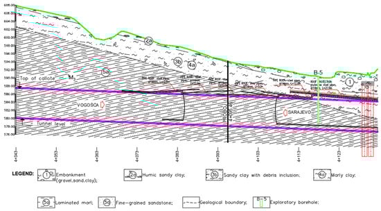
Figure 2.
Geological profile of the Kobilja Glava Tunnel.
The total thickness of the overburden above the tunnel axis is relatively small, classifying this zone as a low overburden area. This geometry creates challenging conditions for construction, as it reduces the natural geostatic pressure that contributes to the stability of the overlying material [21].
In Figure 3, the cross-section of the exploratory borehole B-5 is presented.
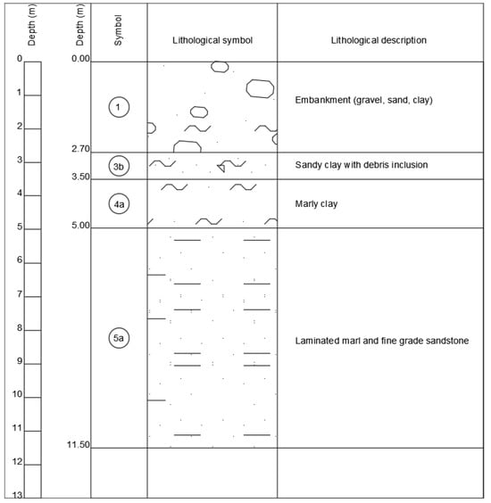
Figure 3.
Cross-section of exploratory borehole B-5.
According to UCS Classification, marls of horizon 5a belong to groups of lean clay (CL-1) and fatty clay (CH-1). The natural volumetric weight is at an average of 21.0 kN/m3. Natural water content is on average 16%. The plasticity index is on average 20.2%. The consistency index is on average 0.99, while the monoaxial strength value is on average 2250 kPa. The test of shear resistance characteristics was performed in a direct shear apparatus, on samples with dimension of 6.05 cm × 6.05 cm and the average internal friction angle was 24° while average cohesion was 32 kPa.
3. Case Study
The construction of the Kobilja Glava Tunnel, as defined by the main project [22], is to be carried out using the New Austrian Tunneling Method (NATM). This method is based on the principle of maximizing the load-bearing capacity of the rock mass or soil, with minimal primary support applied immediately after excavation.
A key concept of the NATM is the continuous observation of rock mass behavior and the flexible adaptation of support measures according to actual field conditions [23]. Fundamentally, the method involves the use of shotcrete, lattice girders, steel mesh, and self-drilling anchors, combined with geotechnical monitoring that enables deformation control and optimization of stabilization measures [24].
The NATM has proven effective in complex geological conditions, especially in zones with variable lithological composition and minimal overburden, as is the case along the Kobilja Glava Tunnel route. By applying flexible support measures and continuously monitoring rock mass behavior, the method maintains ground equilibrium, controls stress redistribution, and reduces settlement risk. This adaptability is crucial for the safe and efficient construction of tunnels in urban environments with complex geotechnical conditions [25,26,27,28]
3.1. Pipe Umbrella as Method of Roof Support Prior to Excavation
A critical factor contributing to the enhanced adaptability of the New Austrian Tunneling Method (NATM) in soft ground and minimal overburden conditions is the systematic implementation of pipe umbrella systems for pre-support during excavation [29]. This technique provides a viable and efficient solution to the associated geotechnical challenges, as it avoids surface excavation and minimizes interference with surface infrastructure and traffic flow [12].
The pipe umbrella method involves installing a series of steel pipes to form a temporary roof that supports the underground space beneath it. This technique is widely used for tunnel excavation under shallow soil cover [30]. The pipe umbrella is constructed in phases by installing steel pipes through boreholes ahead of the tunnel face, creating a protective arch just above the tunnel axis. This configuration enables load redistribution, reduces stresses in the tunnel crown, and stabilizes the excavation face—factors that are particularly important under shallow overburden conditions [31,32,33].
Figure 4 illustrates the roof support method using the pipe umbrella prior to tunnel excavation in the low overburden zone, while Figure 5 shows the flowchart summarizing the sequential steps in the pipe umbrella installation process used for pre-support in low overburden tunnel excavation.
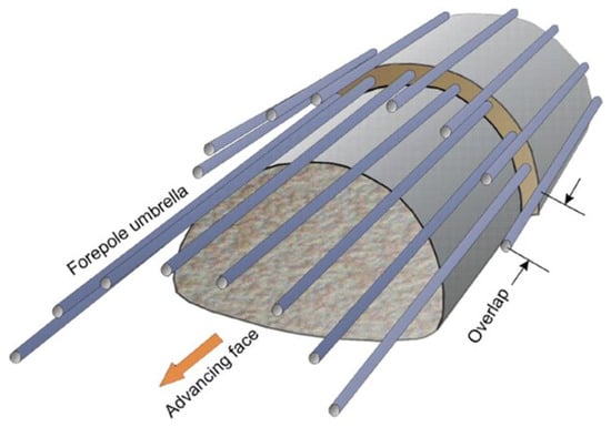
Figure 4.
Principles of installation of pipe shield.
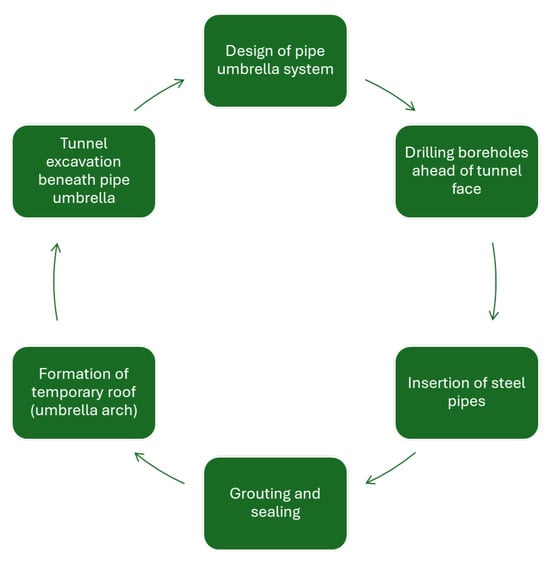
Figure 5.
Flowchart summarizing the sequential steps in the pipe umbrella installation process used for pre-support in low overburden tunnel excavation.
As shown in Figure 5, the flowchart for the sequential steps consists of the following steps. After evaluation of ground conditions and identification of zones with low overburden or soft soil, a proper design of the pipe umbrella system is required (determining pipe length, spacing, inclination, and installation sequence based on geotechnical data). When previous conditions are met, the drilling of a series of boreholes along the designed alignment is performed using a drilling jumbo. When all boreholes are drilled, steel pipes are installed in them and grouting around the pipes to fill voids is applied. The next step is the formation of a temporary roof (umbrella arch) from preinstalled pipes which help in the redistribution of loads and the stabilization of the excavation zone beneath the pipe umbrella.
3.2. Support Measures During the Excavation of the Left Tunnel Tube from the Portal
The excavation of the Kobilja Glava Tunnel required the implementation of advanced and carefully designed support measures to ensure the stability of the tunnel profile and minimize deformations within the rock mass. One of the key solutions was the installation of steel pipes with a diameter of Ø114 mm and a length of 21 m, arranged in two rows with an overlap of 5 m (Figure 6). The boreholes were drilled with an enlarged diameter to allow the formation of a thicker grout layer, which increased the efficiency of cutting potential slip planes and further reduced the load on the left tunnel face slope [34].
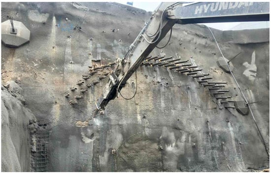
Figure 6.
Initial support measures of the left tunnel tube.
The stabilization of the tunnel excavation involved the use of several support elements: shotcrete, self-drilling anchors (IBOs), reinforcing mesh, and lattice girders. These components proved highly effective in preserving the integrity of the tunnel subgrade. Particularly noteworthy was the use of Ø51 mm IBO anchors with a capacity of 530 kN, installed in the tunnel roof and bench according to a precisely defined layout. These anchors significantly contributed to stabilizing the excavation face and reducing the risk of uncontrolled rock mass movements.
Shotcrete of class C25/30 was applied in layers of varying thickness—5 cm for the initial stabilization of the excavation face and 30 cm for the roof, bench, and invert—achieving effective deformation control and increasing the load-bearing capacity of the subgrade. For additional protection of the excavation face, Q257 reinforcing mesh was installed at every third excavation step, while Ø32 mm IBO anchors, 12 m long, were used to further reinforce the face zone.
For the validation of the adopted support construction, numerical analysis has been conducted using PLAXIS 2D software package. Modeling parameters for shotcrete were selected as follows: thickness d = 0.3 m, axial stiffness EA = 4.5 × 10⁶ kN/m, flexure stiffness EI = 15.0 × 10⁶ kNm2/m, and Poisson’s ratio ν = 0.2. Modeling parameters for anchors were selected as follows: diameter d = 0.051 m, bolt spacing L = 0.8 m, Young’s modulus E = 72.44 × 10⁶ kN/m2, and unit weight γ = 37.23 kN/m3. Deformations, shear forces, axial forces, and bending moments for the chosen support construction are presented in Figure 7.
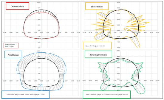
Figure 7.
Deformations, shear forces, axial forces, and bending moments for support construction.
To limit deformation of the surrounding material and the primary support, it was essential to strictly adhere to the technological sequence of the works, ensuring that the distance between the excavation face and the temporary invert did not exceed 2 m.
Compared with practices in other tunnels constructed under similar geological conditions, the applied support measures proved to be an optimal solution for excavation stabilization and effective deformation control. Figure 8 provides an overview of the support measures used for roof stabilization in the low overburden zone of the left tunnel tube.
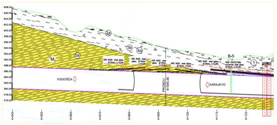
Figure 8.
Roof stabilization in the low overburden zone.
The cross-section of the tunnel with the support type is presented in Figure 9, while the scheme of the anchors is presented in Figure 10.
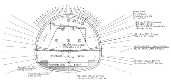
Figure 9.
Cross-section of tunnel with support construction.
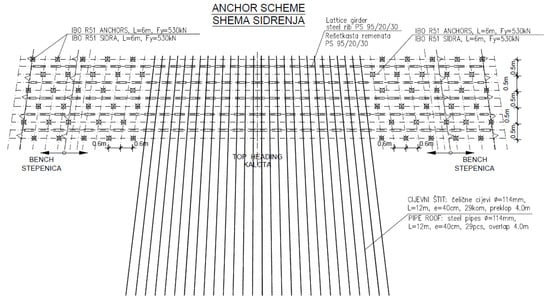
Figure 10.
Anchor scheme.
The longitudinal section of the excavating steps is shown in Figure 11.
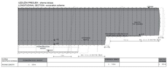
Figure 11.
Longitudinal section of excavating steps.
3.3. Methods of Predicting Surface Deformations
Considerable research efforts have focused on improving the prediction of soil behavior in response to stress changes induced by tunneling, as well as on developing technically demanding mitigation strategies to address these challenges [35]. Owing to the inherent characteristics of the tunneling process, the actual excavated profile typically exceeds the theoretical design, resulting in a series of ground displacements directed toward the excavated spaces. This phenomenon is commonly referred to as ground loss or, more precisely, volume loss [36]. According to Peck [36], surface settlement arises from both radial displacements within the tunnel cross-section and longitudinal deformations along the tunnel axis (Figure 12) [7].
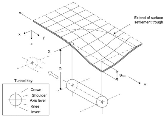
Figure 12.
Subsidence above the advancing tunnel direction [7,36].
A range of methodologies has been developed for the accurate prediction and management of maximum surface settlement, including empirical, analytical, numerical, and artificial intelligence-based approaches [37]. Conventional methods typically rely on empirical correlations or analytical formulations derived from engineering experience and theoretical assumptions. One of the earliest investigations into the surface settlement profile above underground tunnel structures was conducted by Martos [38], who analyzed the initial shape and distribution of the settlement.
Martos [38] proposed that the surface settlement profile above a tunnel can be effectively represented by a normal (Gaussian) distribution curve, as illustrated in Figure 10. Building upon this concept, Peck [36] extended this research by demonstrating the suitability of the Gaussian curve for modeling ground settlement induced by tunnel construction. Through the analysis of settlement data from numerous underground construction projects, he established that the settlement profile is approximately symmetrical about the vertical axis of the tunnel. Based on these findings, a semi-empirical approach was developed to calculate ground settlement, expressed by the following expression:
where SV represents subsidence value, Smax represents theoretical maximum subsidence along the tunnel centerline, x represents lateral distance from the tunnel centerline, and i represents lateral distance from the tunnel centerline to the inflection point in the Gaussian distribution curve.
Empirical equations for estimating surface settlement induced by tunnel construction remain useful for preliminary assessments [39]. However, in complex geological or structural conditions, advanced numerical analyses—particularly finite element analysis (FEA) and soil–structure interaction studies—are recommended to obtain more accurate results [40]. Numerical simulation techniques, such as the finite element method (FEM) and the finite difference method (FDM), provide a more flexible and sophisticated modeling framework. These methods can accommodate a wide range of geotechnical parameters and effectively capture the complex interactions between soil strata and tunnel linings [7]. Owing to their theoretical rigor and adaptability, numerical approaches are widely applied in geotechnical engineering and are regarded as a more realistic methodology for predicting surface settlements [41].
The modeling parameters of the soil used for numerical analysis in Plaxis software are presented in Table 1.

Table 1.
Modeling parameters of soil.
4. Results and Discussion
Numerical analyses were conducted using the finite element method with Plaxis software. The geometry of the model is presented in Figure 13, while the geometry of the excavated model is shown in Figure 14.
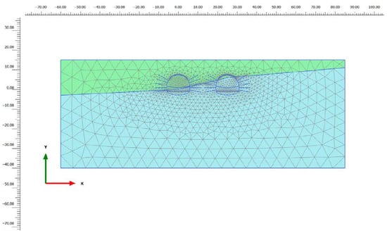
Figure 13.
Model geometry.
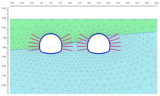
Figure 14.
Model geometry (excavated).
The Plaxis package indicated expected displacements of the left tunnel tube of up to 6.30 cm (Figure 15), with the zone of plastified material around the tunnel confined within a width of 3.0 m (Figure 16). These results were crucial for validating the stability of the tunnel subgrade and for optimizing subsequent excavation phases.
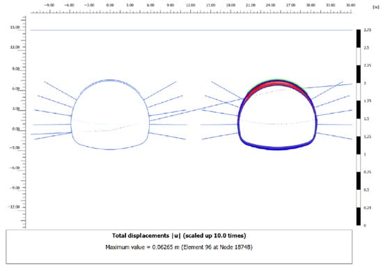
Figure 15.
Display of the results of the settlement assessment expected above the left tunnel tube from the exit.
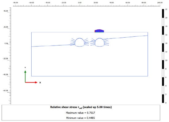
Figure 16.
Display of the relative shear stress values with zone of plastified material around the tunnel confined within a width of 3.0 m.
For broader validation of the numerical results, a comparison was conducted between the measured surface settlements and the empirical model proposed by Peck [36], which approximates the settlement profile above a tunnel using a Gaussian distribution, as expressed by Equation (1). For the purposes of this analysis, the maximum settlement was taken as Smax = 70 mm, while the parameter representing the width of the zone of influence was set to i = 8 m, corresponding to the geotechnical conditions in an area of shallow overburden. The calculated settlement values for distances up to ±10 m from the tunnel axis are presented in Table 2.
Table 2.
Calculated settlement values according to Peck model (Smax = 70 mm and i = 8 m).
The diagram presented below (Figure 17) illustrates the distribution of surface settlements above the tunnel according to Peck’s empirical model. The diagram shows the maximum settlement occurring along the tunnel axis. This visual confirmation further supports the numerical results and demonstrates the reliability of the applied stabilization measures under conditions of shallow overburden.
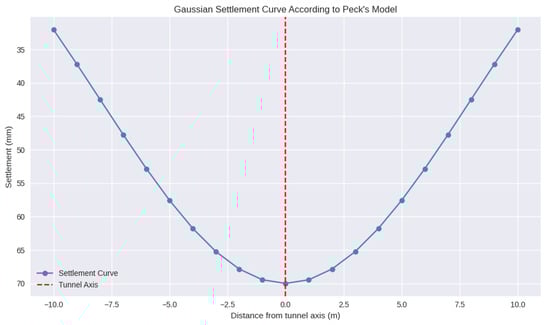
Figure 17.
Settlement distribution above the tunnel according to Peck’s Gaussian model.
Before the start of excavation, a geodetic monitoring system was established on the surface above the left tunnel tube to track ground settlement. Survey profiles were installed at intervals of approximately 10 m, with three markers placed on each profile—one directly above the tunnel axis and two laterally, to the left and right, at a distance of about 10 m from the axis. Monitoring was carried out using standard measuring equipment, specifically a total station.
Simultaneously with numerical modeling, deformations of the primary tunnel lining were monitored under real conditions. The monitoring system included a network of measurement-control profiles and reference points on the surface (Figure 18), enabling the reliable recording of settlements and timely assessment of the excavation’s impact on surface deformations.
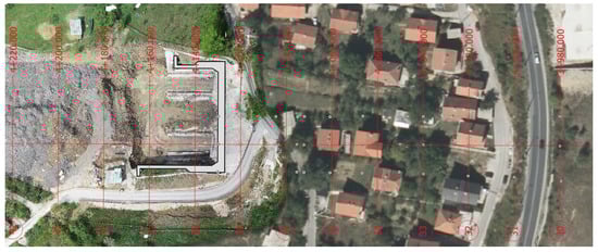
Figure 18.
Arrangement of geodetic markers on the surface above the left tunnel tube.
Figure 19 shows the measured maximum settlements on the ground surface above the left tunnel tube in the low overburden zone, covering the range from the start of excavation at chainage 4 + 133 to chainage 4 + 043. The horizontal axis represents the chainages, while the vertical axis indicates the settlement values in millimeters.
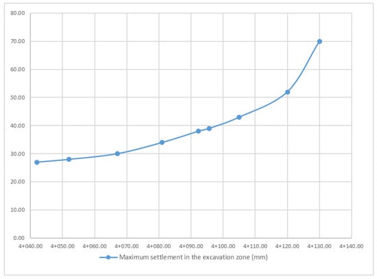
Figure 19.
Results of measurement of settlement on the surface of the ground above the left tunnel tube in the zone of low overburden.
The greatest settlements were recorded at the start of excavation (chainage 4 + 133), where the overburden height was less than 3 m, with settlement values reaching approximately 70 mm. Moving toward lower chainages, as the overburden thickness increased, a gradual decrease in deformations was observed. At chainage 4 + 043, where the overburden reached about 20 m, the settlement was approximately 28 mm.
By comparing the measured values along the alignment (e.g., 70 mm at station 4 + 130, 52 mm at station 4 + 120, etc.), it is confirmed that the actual data align well with the theoretical distribution. This correlation further validates the reliability of the numerical model and the effectiveness of the applied stabilization measures in the shallow overburden zone.
The measured settlements on the site closely matched the limits predicted by numerical modeling, with an accuracy of approximately 90%, confirming the reliability of the computational approach and the validity of the defined input parameters. The reduction in settlement with increasing overburden thickness can be explained by the redistribution of stresses through the surrounding rock mass. When the overburden height exceeds twice the tunnel diameter (H > 2D), the rock mass bears a significant portion of the load, acting as a natural supporting element. This mechanism, known as the arching effect, reduces the load on the tunnel lining and limits deformations [35,42,43,44].
For a precise assessment of the impact of tunnel excavation on surrounding structures, a settlement of 70 mm was further analyzed through calculations of maximum tensile strain (εt) and angular distortion (θ), with the results then correlated to damage classification schemes according to Boscardin and Cording [45] and Burland [46].
At the site corresponding to chainage 4 + 080, the first structure, located directly above the axis of the left tunnel tube, with a length of L = 10 m and a height of 10 m, was subjected to a deformation assessment based on the measured differential settlement of 20 mm (0.02 m). The structure is a residential, masonry construction with reinforced foundations.
Angular distortion (θ) is defined as the ratio of the differential settlement of the structure to its length L:
In our case, it is as follows:
According to the damage classification presented in Table 3, θ = 1/500 places the structure in the “Negligible/Minor” category, indicating minimal or superficial cracks with no significant impact on the structural stability.
Table 3.
Damage classification based on angular distortion (θ) [46].
Field observations and the calculated results confirmed that the risk of damage to the structure is minimal. The measured values of angular distortion (θ) and maximum tensile strain (εt) place the structure in the “Negligible/Minor” categories, which is consistent with the visual assessment. Damage is limited to very fine cracks, primarily on external surfaces such as sidewalks, with no impact on the load-bearing elements of the structure.
5. Conclusions
The construction of a tunnel under shallow overburden in a densely populated urban area, as in the case of the left tunnel tube of the Kobilja Glava Tunnel, represents a significant technical and safety challenge due to the limited thickness of the rock mass above the excavation, variable geomechanical properties, and the proximity of existing structures. This study demonstrates that careful selection of the excavation method and support measures, combined with continuous geotechnical monitoring, is crucial for controlling deformations and ensuring structural stability.
The application of the New Austrian Tunneling Method (NATM), complemented by additional roof support using a pipe umbrella, allowed for gradual advancement and adaptive adjustment to in situ conditions. Systematic pre-support using steel pipes with a diameter of Ø114 mm, in combination with shotcrete, self-drilling anchors, and reinforcement meshes, proved effective in reducing stresses in the tunnel crown, stabilizing the excavation face, and limiting surface settlements.
Numerical modeling conducted in Plaxis predicted displacements of up to 6.30 cm and plasticization of the soil within a zone approximately 3 m wide, while field measurements recorded maximum settlements of approximately 70 mm in areas of minimal overburden (<3 m). As the overburden increased toward chainage 4 + 043 (overburden approximately 20 m), settlements decreased to about 28 mm. The close agreement between modeling results and field monitoring confirms the reliability of the computational parameters and the effectiveness of the applied engineering solutions.
The observed trend of decreasing settlement with increasing overburden confirms the theoretically known arching effect, whereby for H > 2D, the rock mass carries a significant portion of the load, relieving the tunnel lining. This mechanism substantially contributes to stability and deformation control, which is particularly important in urban environments with strict requirements to limit the impact on surface structures.
In conclusion, the combination of the NATM with the targeted use of the pipe umbrella and precise settlement monitoring ensured the stability of the tunnel under extremely complex shallow overburden conditions. This integrated approach can serve as a reliable model for the design and construction of tunnels in similar geotechnical and urban settings.
Author Contributions
Conceptualization, E.B. and L.C.; methodology, E.B.; software, S.F.; validation, K.G., R.T. and Z.P.; formal analysis, E.B.; investigation, S.F.; data curation, S.F. and E.B.; writing—original draft preparation, E.B.; writing—review and editing, L.C.; visualization, E.B., L.C. and S.F.; supervision, K.G. All authors have read and agreed to the published version of the manuscript.
Funding
This research received no external funding.
Data Availability Statement
The original contributions presented in this study are included in the article. Further inquiries can be directed to the corresponding author.
Acknowledgments
The authors from the University of Belgrade, Faculty of Mining and Geology would like to express their sincere gratitude for the support provided by the Ministry of Science, Technological Development, and Innovation of the Republic of Serbia, within the framework of support for scientific research at the University of Belgrade, Faculty of Mining and Geology in Belgrade, under contract number 451-03-136/2025-03/200126.
Conflicts of Interest
Author Satko Filipović was employed by Ministry of Transport of Sarajevo Canton. The author declare that the research was conducted in the absence of any commercial or financial relationships that could be construed as a potential conflict of interest.
References
- Bektašević, E.; Filipović, S.; Gutić, K.; Musa, N. Definiranje Optimalnog Razmaka Između Tehnoloških Sekvenci Pri Iskopu Tunela U Lošijoj Stjenskoj Masi. E-Zb. Elektron. Zb. Rad. Građevinskog Fak. 2024, 14, 45–55. [Google Scholar] [CrossRef]
- Bektašević, E.; Mušija, A.; Gutić, K.; Beganović, S.; Čehajić, D. Analysis of the groundwater influence on the categorization of the rock mass and support type of the Zenica tunnel on the route of the VC corridor. J. Fac. Civ. Eng. 2023, 44, 5–19. [Google Scholar] [CrossRef]
- Bektašević, E.; Gutić, K.; Kadrić, R.; Kadrić, S.; Sikira, D. Deformation analysis during tunnel excavation in poor rock mass. In Proceedings of the 8th International Conference on Road and Rail Infrastructures–CETRA, Cavtat, Croatia, 15–17 May 2024; pp. 799–805. [Google Scholar]
- Bektašević, E.; Antičević, H.; Gutić, K.; Sikira, D. Application of seismic methods for determining the depth of the rock mass damage zone around the excavation profile by blasting. Glob. J. Eng. Technol. Adv. 2024, 18, 139–151. [Google Scholar] [CrossRef]
- National Highway Institute (US); Parsons Brinckerhoff, Quade & Douglas. Technical Manual for Design And Construction of Road Tunnels—Civil Elements; AASHTO: Washington, DC, USA, 2010.
- Lee, K.; Kim, H. Analysis of ground surface settlement in a shallow tunnel using coupled Eulerian-Lagrangian technique. Bull. Eng. Geol. Environ. 2025, 84, 337. [Google Scholar] [CrossRef]
- Bektašević, E.; Filipović, S.; Gutić, K.; Hodžić, D.; Musa, N. Analysis of Surface Deformations During Excavation of A Small Overburden Tunnel in Weak Rock Masses. J. Fac. Civ. Eng. Archit. 2025, 40, 35–48. [Google Scholar] [CrossRef]
- Djenane, M.; Bezih, K. Shallow tunneling’s impact on surface settlements. J. Eng. Exact Sci. 2024, 10, 18591. [Google Scholar] [CrossRef]
- Jahangir, E. Impacts of Shallow Tunneling in Urban Areas. Mines ParisTech—PSL Research University. 2015. Available online: https://alertgeomaterials.eu/wp-content/uploads/2015/03/Shallow-tunnels-Mines-ParisTech.pdf (accessed on 20 October 2025).
- Haundi, T.; Nangulama, H.K.; Mbewe, V.R. Site characterisation, deep basement support, construction, and deformation control. Geotech. Geol. Eng. 2024, 42, 1611–1622. [Google Scholar] [CrossRef]
- Yang, Y.F.; Liao, S.M.; Liu, M.B.; Wu, D.P.; Pan, W.Q.; Li, H. A new construction method for metro stations in dense urban areas in Shanghai soft ground: Open-cut shafts combined with quasi-rectangular jacking boxes. Tunn. Undergr. Space Technol. 2022, 125, 104530. [Google Scholar] [CrossRef]
- Jiang, X.; Zhang, X.; Zhang, X.; Long, L.; Bai, Y.; Huang, B. Advancing Shallow Tunnel Construction in Soft Ground: The Pipe-Umbrella Box Jacking Method. Transp. Res. Rec. J. Transp. Res. Board 2024, 2678, 150–168. [Google Scholar] [CrossRef]
- Lu, C.; Zhang, X.; Shi, B.; Jiang, J.; Lin, Z. Deformation in settlement and grouting remediation of thickened larger-diameter metro shield tunnel in soft soil: A case study. Case Stud. Constr. Mater. 2024, 20, e02736. [Google Scholar] [CrossRef]
- Wang, X.; Li, Z.; Li, W.; He, C.; Wang, Z. Analysis and prediction of dynamic stress concentration in jointed coal using boundary element method. Theor. Appl. Fract. Mech. 2025, 140, 105136. [Google Scholar] [CrossRef]
- Yang, W.; Chen, Z.; Zhao, H.; Li, J.; Chen, S.; Shi, C. Physical feature shared online transfer learning framework for cross-engineering rock mass quality perception during TBM excavation. Tunn. Undergr. Space Technol. 2025, 168, 107111. [Google Scholar] [CrossRef]
- Jin, H.; Yuan, D.; Zhou, S.; Zhao, D. Short-term and long-term displacement of surface and shield tunnel in soft soil: Field observations and numerical modeling. Appl. Sci. 2022, 12, 3564. [Google Scholar] [CrossRef]
- Filipović, S.; Bektašević, E.; Gutić, K.; Musa, N.; Sakić, N. Research on the phenomenon of increasing borehole diameter at the installation of rod anchors in marl using wet technology compared to dry drilling procedure. Glob. J. Eng. Technol. Adv. 2025, 22, 1–14. [Google Scholar] [CrossRef]
- Yuan, X.; Wang, H.; Kang, S.; Liu, C.; Chen, Y.; Zhou, X.; Wu, C.; Zhu, H.; Yang, C.; Zhu, Y.; et al. Factors influencing ground settlement during tunnel proximity construction. Sustainability 2023, 15, 13270. [Google Scholar] [CrossRef]
- Kadrić, S.; Bektašević, E.; Gutić, K.; Sikira, D. Numeričke analize stabilnosti iskopa tunela ibarac i stabilizacija urušenog dijela, parking niše. Nauka Praksa 2023, 26, 1–9. [Google Scholar] [CrossRef]
- Li, Y.; Zhou, G.; Li, T.; Tang, C.A.; Gong, B.; Wang, K. Influence of tunnel excavation on the deformation of a frame building. Buildings 2023, 13, 810. [Google Scholar] [CrossRef]
- Mair, R.J.; Taylor, R.N. Bored Tunnelling in the Urban Environments. In Fourteenth International Conference on Soil Mechanics and Foundation Engineering. Proceedings International Society for Soil Mechanics and Foundation Engineering. 1999, Volume 4. Available online: https://www.issmge.org/uploads/publications/1/31/1997_04_0049.pdf (accessed on 20 October 2025).
- IRGO Consulting d.o.o.; Lotus d.o.o. Glavni Projekt Izmjene Projekta Tunela Kobilja Glava“ na I Transverzali, od km 3 + 420.00 do km 4 + 180.00, Knjiga D, Mapa D.4 Tunelski Iskop; IRGO Consulting d.o.o.: Sarajevo, Ljubljana; Lotus d.o.o.: Sarajevo, Ljubljana, 2023. [Google Scholar]
- Rabcewicz, L. The New Austrian Tunnelling Method (NATM), Part I–III [PDF Lecture Notes]; University of British Columbia: Endowment Lands, Canada, 1964; Available online: https://www.eoas.ubc.ca/courses/eosc547/lecture-material/Rabcewicz-NATM.pdf (accessed on 20 October 2025).
- Jovanović, P. Izrada Podzemnih Prostorija Velikog Profila; Građevinska knjiga: Serbia, Beograd, 1978. [Google Scholar]
- De Farias, M.M.; Junior, A.H.M.; De Assis, A.P. Displacement control in tunnels excavated by the NATM: 3-D numerical simulations. Tunn. Undergr. Space Technol. 2004, 19, 283–293. [Google Scholar] [CrossRef]
- Kavvadas, M.J. Monitoring ground deformation in tunnelling: Current practice in transportation tunnels. Eng. Geol. 2005, 79, 93–113. [Google Scholar] [CrossRef]
- Rabcewicz, L.V. The New Austrian Tunneling Method. Part One—Principles of the Method. Water Power 1965, 17, 453–457. [Google Scholar]
- Kanojiya, S.; Mehta, G.K. Comprehensive deformation study in the new Austrian tunneling technique tunnel utilising artificial neural network model. AiBi Rev. Investig. Adm. E Ing. 2024, 12, 164–176. [Google Scholar] [CrossRef]
- Nitschke, A.; Gall, V.; Ahuja, V. Modeling of pipe arch canopies in shallow soft ground tunnels constructed by sequential excavation methods. In Proceedings of the EURO: TUN 2009 2nd International Conference on Computational Methods in Tunnelling, Bochum, Germany, 9–11 September 2009; pp. 9–11. [Google Scholar]
- Bektašević, E.; Gutić, K.; Sikira, D. Tunneling—With Practical Examples; LAP LAMBERT Academic Publishing: Saarbrücken, Germany, 2024; ISBN 978-620-7-80623-2. [Google Scholar]
- Volkmann, G.; Button, E.; Schubert, W. A contribution to the design of tunnels supported by a pipe roof. In Proceedings of the ARMA US Rock Mechanics/Geomechanics Symposium, Golden, Colorado, 17–21 June 2006; ARMA. p. ARMA-06. [Google Scholar]
- Zhang, Z.; Li, H.; Liu, H.; Li, G.; Shi, X. Load transferring mechanism of pipe umbrella support in shallow-buried tunnels. Tunn. Undergr. Space Technol. 2014, 43, 213–221. [Google Scholar] [CrossRef]
- TerraRoc. Pipe Roofing Solutions. 2024. Available online: https://terrarocdrilling.com/drilling-equipment/drill-tools/casing-advancement-systems/pipe-roofing/ (accessed on 20 October 2025).
- IRGO Consulting d.o.o.; Lotus d.o.o. Geotehnička misija G32 br.32, Prijedlog br. 8.2; IRGO Consulting d.o.o.: Sarajevo, Ljubljana; Lotus d.o.o.: Sarajevo, Ljubljana, 2024. [Google Scholar]
- Loganathan, N.; Poulos, H.G. Analytical prediction for tunneling-induced ground movements in clays. J. Geotech. Geoenvironmental Eng. 1998, 124, 846–856. [Google Scholar] [CrossRef]
- Peck, R.B. Advantages and limitations of the observational method in applied soil mechanics. Geotechnique 1969, 19, 171–187. [Google Scholar] [CrossRef]
- Moghaddasi, M.R.; Noorian-Bidgoli, M. ICA-ANN, ANN and multiple regression models for prediction of surface settlement caused by tunneling. Tunn. Undergr. Space Technol. 2018, 79, 197–209. [Google Scholar] [CrossRef]
- Martos, F. Concerning an approximate equation of the subsidence trough and its time factors. In International strata control congress, Leipzig; Section fur Bergbau; Deutsche Akademie der Wissenschaften zu Berlin: Berlin, Germany, 1958; pp. 191–205. [Google Scholar]
- Taylor, R.N. Modelling of Tunnel Behaviour. Proc. Inst. Civ. Eng.Geotech. Eng. 1998, 131, 127–132. [Google Scholar] [CrossRef]
- Elmanan, A.A.; Elarabi, H. Analysis of surface settlement due to tunneling in soft ground using empirical and numerical methods. In Proceedings of the The Fourth African Young Geotechnical Engineer’s Conference, Casablanca, Morocco, 12–13 November 2015. [Google Scholar]
- Zhang, P.; Wu, H.N.; Chen, R.P.; Chan, T.H. Hybrid meta-heuristic and machine learning algorithms for tunneling-induced settlement prediction: A comparative study. Tunn. Undergr. Space Technol. 2020, 99, 103383. [Google Scholar] [CrossRef]
- Cao, L.; Cui, W.; Qin, Z.; Xu, R.; Wang, T.; Liu, Y. Analysis of Arch Forming Factors of Shallow Buried Hard Rock Tunnel under Overlying Load. Buildings 2023, 13, 2210. [Google Scholar] [CrossRef]
- Alsirawan, R.; Sheble, A.; Alnmr, A. Two-Dimensional Numerical Analysis for TBM Tunneling-Induced Structure Settlement: A Proposed Modeling Method and Parametric Study. Infrastructures 2023, 8, 88. [Google Scholar] [CrossRef]
- Smith, A.G.; Pells, P.J.N. Impact of fire on tunnels in Hawkesbury sandstone. Tunn. Undergr. Space Technol. 2008, 23, 65–74. [Google Scholar] [CrossRef]
- Boscardin, M.D.; Cording, E.J. Building response to excavation-induced settlement. J. Geotech. Eng. 1989, 115, 1–21. [Google Scholar] [CrossRef]
- Burland, J.B. Assessment of risk of damage to buildings due to tunnelling and excavatioins. In Proceedings of the 1st Int. Conf. on Earthquake Geotech. Engrg., IS-Tokyo’95, Tokyo, Japan, 14–16 November 1995. [Google Scholar]


Disclaimer/Publisher’s Note: The statements, opinions and data contained in all publications are solely those of the individual author(s) and contributor(s) and not of MDPI and/or the editor(s). MDPI and/or the editor(s) disclaim responsibility for any injury to people or property resulting from any ideas, methods, instructions or products referred to in the content. |
© 2025 by the authors. Licensee MDPI, Basel, Switzerland. This article is an open access article distributed under the terms and conditions of the Creative Commons Attribution (CC BY) license (https://creativecommons.org/licenses/by/4.0/).