Article

Low-Cost Laser Powder Bed Fusion-Based Additive Manufacturing of Densified Ceramics

School of Aerospace and Mechanical Engineering, Gallogly College of Engineering, The University of Oklahoma, 865 Asp Ave, Felgar Hall, Norman, OK 73019, USA
*
Author to whom correspondence should be addressed.
Appl. Sci. 2025, 15(22), 12091; https://doi.org/10.3390/app152212091
Submission received: 23 October 2025 / Revised: 9 November 2025 / Accepted: 12 November 2025 / Published: 14 November 2025

Abstract

This article investigates the feasibility of additively manufacturing densified alumina-based ceramics using laser powder bed fusion (LPBF) with ceramic substrates at low cost. Relationships between process parameters and geometric bead characteristics are quantified using Canny edge detection methods. A set of process parameters that result in continuous melt pool formation and solidification is presented. Remelting and intralayer fusion are also identified, demonstrating for the first time that a low-cost diode laser can achieve densification in an impure RTG substrate, indicating that densification and intralayer fusion are achievable.

1. Introduction

Ceramics have demonstrated outstanding performance in environments that require high thermal stability, hardness, and resistance to abrasion and corrosion. The applications of ceramics span a broad range of engineering fields, including thermal protection systems for spacecraft, hot-section components in gas turbines, nuclear systems, subsurface drilling and wear tooling, and high-performance braking components in automobiles [1,2,3]. Despite their favorable properties, conventional ceramic manufacturing imposes stringent constraints on part geometry, typically limiting internal features, graded architectures, and integrated interfaces. Therefore, many application-relevant designs remain impractical or uneconomical using traditional manufacturing processes.
Additive manufacturing (AM) of ceramics offers a unique approach to overcome these geometric constraints, enabling lattice infills, conformal cooling channels, topology-optimized forms, and built-in fixturing features. Among AM technologies, Laser Powder Bed Fusion (LPBF) is attractive for its layer-wise precision and potential for near-net-shape, high-density builds [4,5,6,7]. However, significant barriers limit the broad adoption of AM systems for ceramics. Compared with polymers and metals, the LPBF of ceramic materials can face substantial technical challenges, including dissociation under localized high-energy input, high porosity, destabilizing the melt pool, and steep thermal gradients resulting in the elevated residual stresses that generate cracking in brittle material systems [8,9,10]. Additional thermo-chemical and thermo-mechanical challenges, such as balling, lack-of-fusion defects, and geometric inaccuracy, can narrow the viable process window [11,12,13]. Solving these technical issues requires significant investments in research and system development, resulting in high system costs for AM systems used in ceramics. This high expense acts as a substantial barrier, preventing academic institutions, small businesses, and start-ups from accessing these cutting-edge technologies for AM of ceramics. Therefore, the development of low-cost LPBF systems with optimized process parameters for the AM of ceramic powder materials is challenging but also urgently needed.
While most industrial LPBF systems rely on high-power (100–1000 W) fiber or CO2 lasers, their cost is prohibitive for many researchers [14,15,16]. Recent efforts in low-cost AM have explored the use of diode lasers, which offer a compelling balance of cost-effectiveness and sufficient power density for processing polymers and some composites. However, their application in processing ceramics, which have high melting points and unique thermal properties, remains largely unexplored.
The viability of using ceramics as a substrate in the LPBF process, as a topic of growing research interest, is rapidly expanding. Current research focuses on mitigating defect formation during the AM processes. LPBF and other AM processes depend on stable liquid melt pools for the fusion of dense material [4]. Ceramic substrates are prone to sublimation, dissociation, and other chemical reactions, which can act to destabilize the melt pool, making the process challenging [8]. Furthermore, residual stresses inherent to localized heating and cooling processes can lead to increased cracking in ceramic parts, which are generally more brittle than other materials, such as metals [17]. Investigations have also focused on optimizations to decrease dimensional errors [18]. Multiple review articles have extensively covered the state of the art in this technology [19,20].
The novelty of this work is the exploration of an ultra-low-cost paradigm for ceramic LPBF-based AM. The objectives of this empirical study are: (1) To demonstrate the feasibility of forming a stable melt pool in a low-cost, alumina-based substrate using only a 5 W diode laser. (2) To conduct a parametric study mapping the relationship between scanning energy density (SED), substrate composition (SiO2 additive), and the resulting geometric properties (bead width, bead uniformity). (3) To provide evidence of intralayer fusion and identify key process-induced defects. The outcomes of this study demonstrate that the planned objectives have been achieved.

2. Materials and Methods

An experiment was designed to assess the viability of fabricating fully dense structures by LPBF of ceramic substrates and to investigate the effects of SED variation and SiO2 inclusion on the bead width and uniformity of the fabricated structures.

2.1. Machine Specifications

An LPBF machine was developed in-house to perform experiments. The machine consists of a Cartesian gantry system built from aluminum extrusions, with a usable build volume of 115 × 115 mm. A custom-designed, gantry-mounted recoater blade ensures a flat powder surface. The system is controlled by the Klipper firmware suite, which was adapted for this SLP application. For these single-layer experiments, the powder was manually loaded into the build area and leveled once using the recoater blade. The build platform is a 6061 aluminum plate. The design of the in-house developed LPBF system is shown in Figure 1. The machine is equipped with a LASER TREE LT-40W-AA diode laser (Shenzhen, China) that produces a 450 nm beam of 5 W optical power and moves on a Cartesian gantry. For all experimentation, the focal diameter, or laser spot size, was calibrated to 1 mm using a macroscopic camera and reference scale. All experiments were performed without employing bed adhesion or bed heating, such that the fabricated specimens were suspended in the powder substrate.

2.2. Materials and Substrate Mixtures

All experiments were performed using substrate mixtures with rock tumbler grit (RTG) acting as the base constituent. Qualitative Energy Dispersive X-Ray Spectroscopy revealed that the base constituent of the RTG is black fused alumina with impurities of silica, silicon carbide, and iron oxide. Two granularities of Silicon Dioxide were selected to be used as substrate additives. The rationale for this material choice was central to the project’s low-cost objective. RTG and common silica anti-caking agent are inexpensive and widely available. This study sought to determine if such non-ideal, non-spherical, and impure feedstocks could be processed, providing a baseline for an accessible ceramic AM platform. The details of the powder feedstocks are shown in Table 1.
To prepare the substrate mixtures, the constituent powders, measured by noncompacted volume, were combined in a sealed container. The container was then manually agitated for 15 min to ensure uniform dispersion of the components. Eight substrate mixtures were prepared using non-compacted volumetric parts of the constituents. The RTG was used as the base constituent for each mixture. Mixtures containing the 57.8 μm SiO2 particulate and those with 20 nm SiO2 particulate are labeled with A and B, respectively, in the Mixture Name. The substrate mixtures are tabulated in Table 2 below.
Substrate mixtures containing concentrations of less than 70 vol% RTG with 20 nm SiO2 additive and mixtures containing less than 60 vol% RTG with 57.8   μ m SiO2 additives are not documented because no continuous melt pools formed in these substrate mixtures.

2.3. Environmental Conditions

For all experiments, the printing volume was open to the atmosphere at standard room temperature. No shielding gas or substrate temperature control was applied.

2.4. Scanning Energy Density Variations

Specimens were fabricated using a single track, straight, and continuous laser, 20 mm in length. SED was varied indirectly by varying the scanning velocity alone. Nine variations in SED, ranging from 0.05 to 0.45 J/mm2 in increments of 0.05 J/mm2, were tested for each substrate mixture. SEDs above this range resulted in melt pool instability and stagnation, also known as the balling effect. SEDs below this range resulted in fabricated specimens that were too delicate for analysis. Each SED and substrate mixture combination was triplicated.

2.5. Measurements and Data Analysis

To measure the bead widths of each specimen, a Keyence VHX-7000 (Osaka, Japan) captured a depth composite image of each specimen at 50× magnification. The edges of the specimens were detected by the VHX-7000 software. The distance between the Parallel Least Squares Linear Regressions of the opposing detected edges provided the width of each specimen. The raw data from the edge detections were not directly available from the VHX-7000 software; however, the images were overlaid with the detected edge points colored yellow.
To recapture the raw data, an image processing MATLAB R2024b script was employed to recapture the yellow detected edge points in each image. To measure the uniformity of the fabricated beads, the Root Mean Square Error (RMSE) with respect to the linear regression of the edge was computed. An example of the results of this procedure is shown in Figure 2.
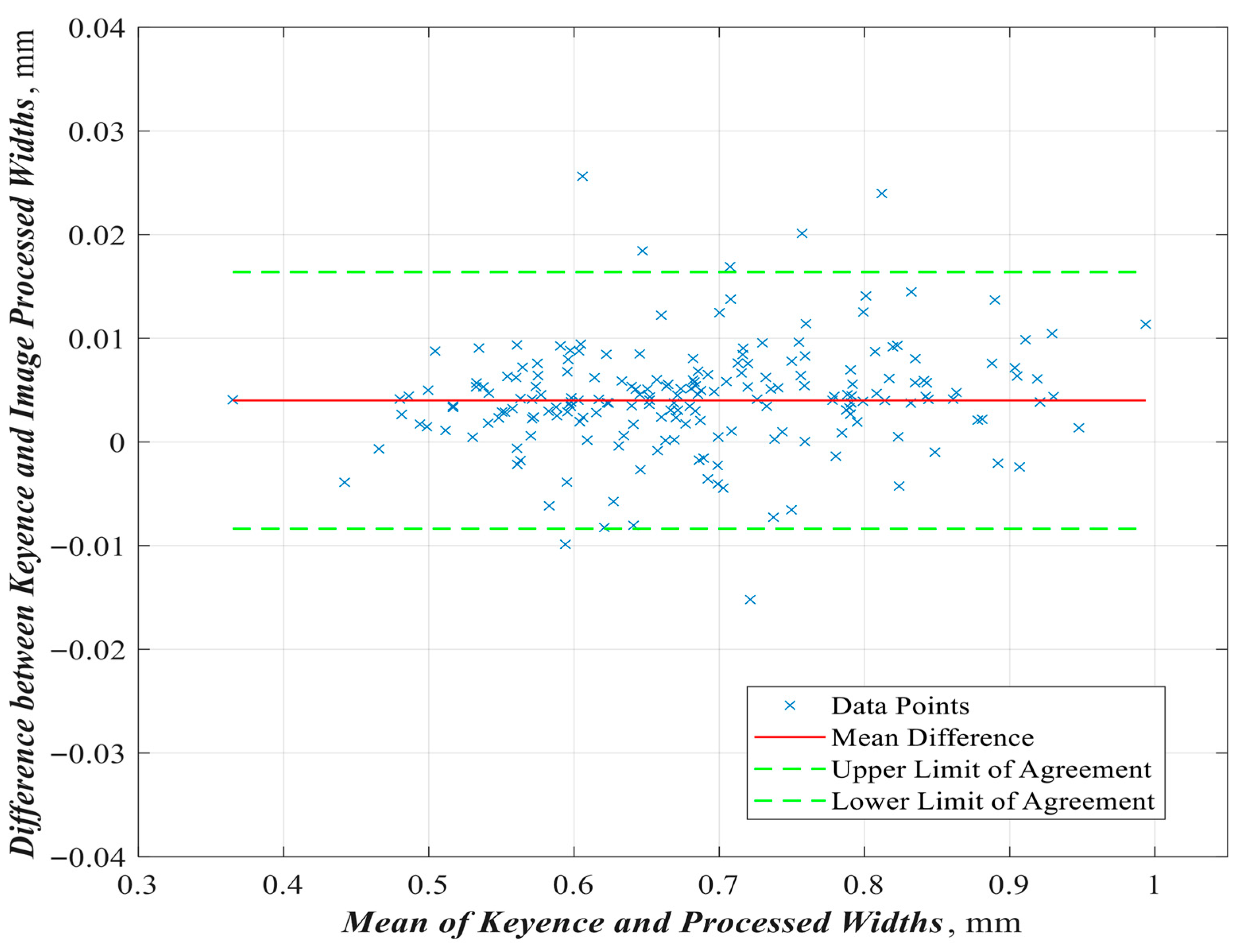
To ensure that the edge data was accurately recaptured by the image processing script, a Bland–Altman Analysis of the two edge detection techniques was conducted. The resulting bead width measurements from each method were used for comparison because this was the only data available from the results of the Keyence Software. The result of this analysis is shown in Figure 3.
The Bland–Altman analysis reveals that a bias of +0.004 mm in width was introduced by the image processing routine. This bias was likely a result of the unidirectional scanning algorithm meeting detected edge pixels that were diffused by the image compression algorithm. However, the bias introduced only represents 0.59% of the line width in the worst case, and only 3.14% of the data fell outside the Bland–Altman limits of agreement. Therefore, the measurements taken by the Keyence VHX-7000 and those using the custom image processing algorithm are in strong agreement.
The uncertainty in the processed line width measurements is the standard deviation of the difference between the processed width and the width collected by the Keyence Microscope, which is 0.0063 mm. This uncertainty is 0.92% of the average line width; therefore, the bias introduced by the processing routine is not great enough to have a significant impact on the trends observed and the qualitative conclusions of the experiments.
A second experiment was designed to qualitatively investigate the viability of intralayer bonding and associated phenomena. For this experiment, 20 mm square specimens were fabricated with varying SED and hatch spacing.

3. Results and Discussions

3.1. Effect of Substrate Mixture and SED Variation

3.1.1. Fabricated Bead Width

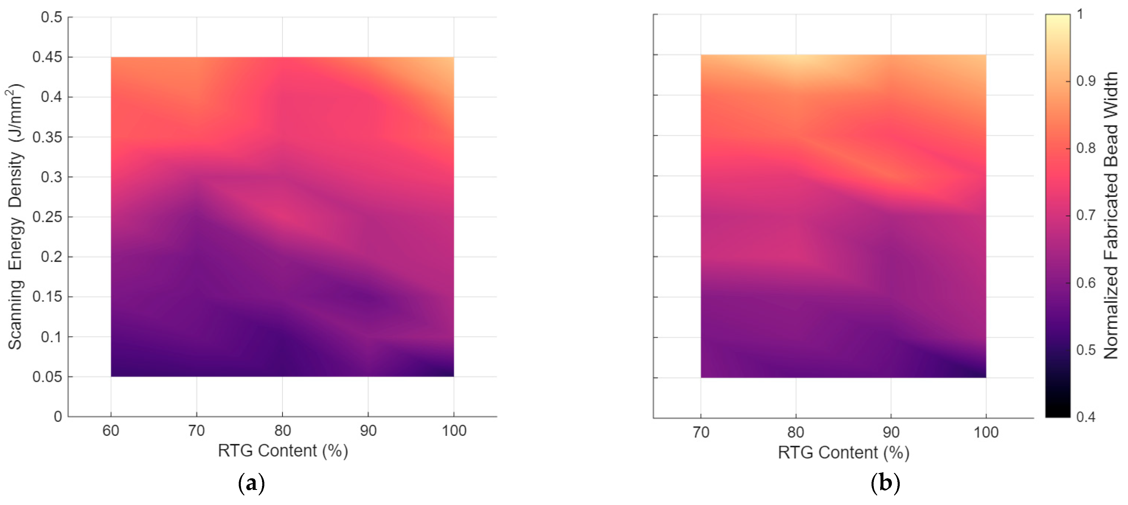
Figure 4 provides a comprehensive map of the processing window. The x-axis represents the vol% of RTG, and the y-axis represents the SED. The color of the map at any point corresponds to the resulting normalized fabricated bead width (NFBW). The NFBW, calculated with respect to the laser spot diameter, across the triplicated specimens is plotted with respect to SED and substrate RTG content, and grouped by SiO2 additive granularity. As shown in Figure 4, the NFBW increases predictably with a higher SED, which is consistent with established LPBF principles. This is because higher energy input creates a larger and more stable melt pool. The maps also reveal that the 20 nm SiO2 additive (Figure 4b) appears to yield a wider processing window for achieving a high NFBW (regions of 0.8–1.0) compared to the 57.8 μm additive (Figure 4a).
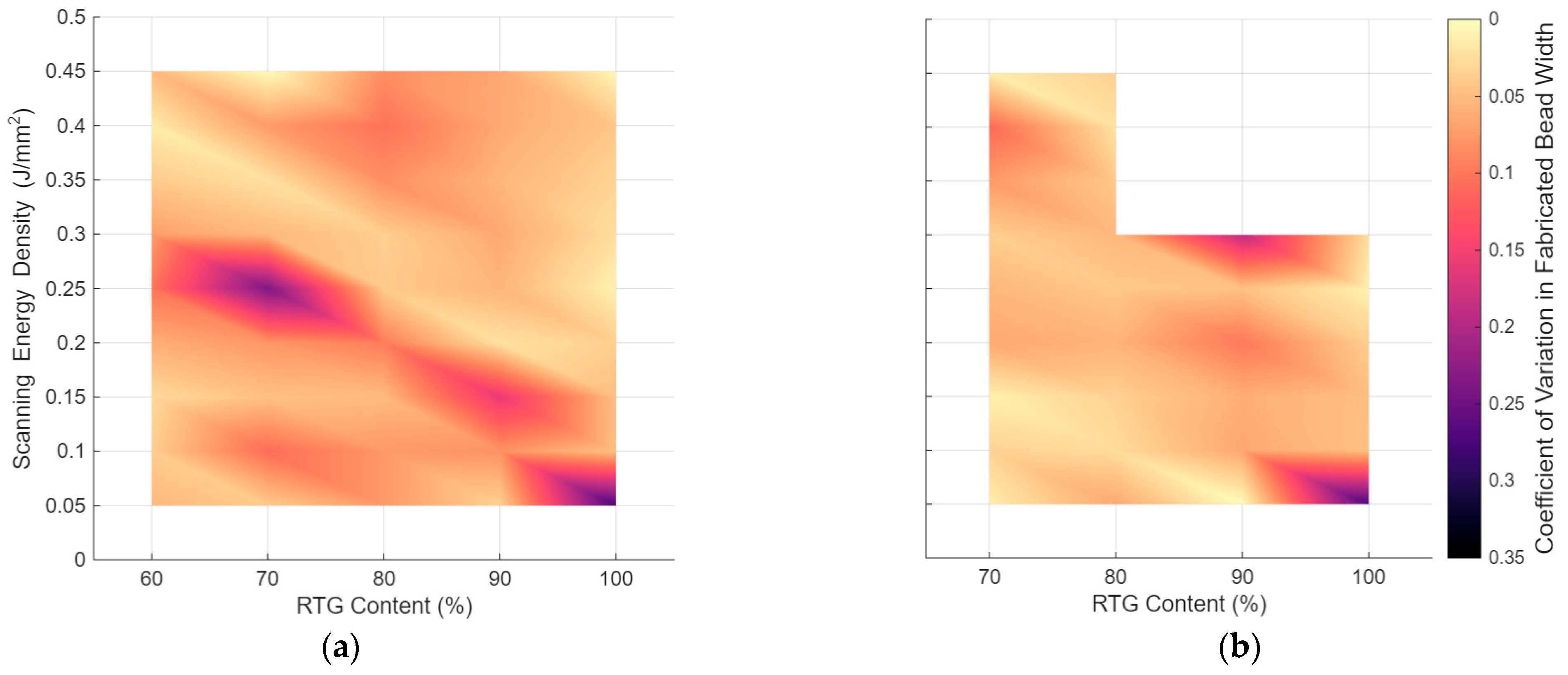
The trend observed in Figure 3 shows an increase in NFBW with increased SED. The data are tabulated in the Appendix A Table A1. The coefficients of variance in the NFBW measurements were plotted with respect to the SED and Substrate ceramic vol% and grouped by SiO2 additive granularity. The results are shown in Figure 5.

3.1.2. Fabricated Bead Uniformity

The roughness of the edge of the fabricated bead in the LPBF process is affected by the homogeneity of the substrate and the stability of the scanning melt pool. Statistical measures of the residuals of the detected edge linear regression, used to define the edge locations, were used to assess the uniformity of the fabricated beads.
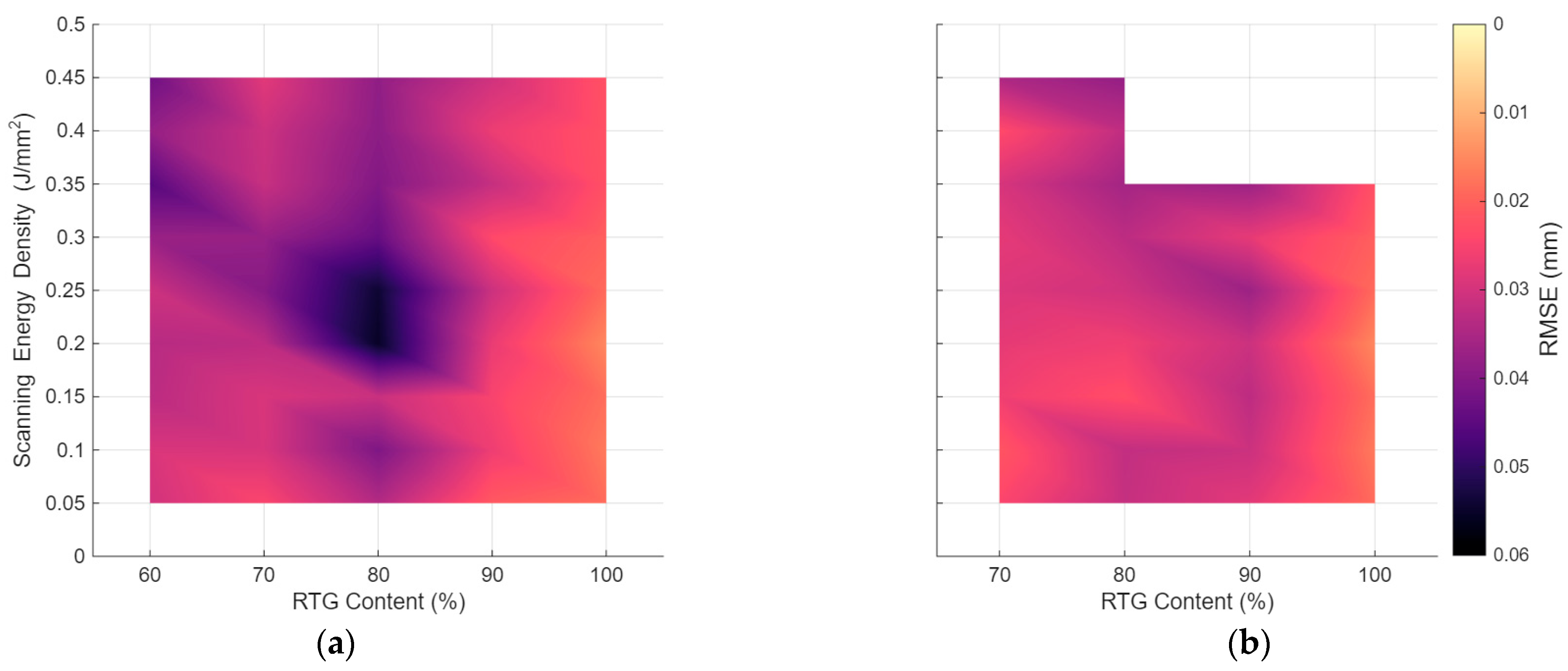
The average Root Mean Square Errors (RMSE) of the residuals from both detected edge linear regressions for each specimen, across the triplicated specimens, are plotted with respect to SED and substrate ceramic volume percentage, and grouped by SiO2 additive granularity. Figure 6 illustrates the bead uniformity via RMSE. The 100 vol% RTG substrates (right-hand side of both maps) clearly show the lowest RMSE (highest uniformity), particularly at lower- to mid-range SEDs. The addition of SiO2, in any amount, appears to decrease melt pool stability and increase bead irregularity. This is likely due to the introduction of more complex, multi-phase melting and cooling dynamics. The dark purple region in Figure 5a around 80% RTG and 0.2 J/mm2 indicates a “sweet spot” of high uniformity (low RMSE) for that specific mixture, a finding that merits further investigation. Note that a lower RMSE indicates a fabricated bead with higher uniformity and, therefore, higher melt pool geometric stability during the fabrication process.
Our findings are significant for the development of low-cost AM solutions for ceramic materials. The observed melt pool instabilities and higher RMSE values (0.015–0.055 mm) are greater than those reported for high-purity alumina processed with high-power lasers. This is an expected trade-off between the irregular particle shape and impurities in the RTG feedstock, resulting in inconsistent energy absorption and melt pool dynamics.
The measured RMSEs across the domain of process parameters tested range from 0.015 to 0.055 mm. The maximum average RMSE occurs in the 80 vol% RTG with a 57.8 μm substrate. This average RMSE equates to 12.7% of the lowest line width measured in the corresponding case. The substrate with 100% RTG resulted in fabricated beads with the lowest average RMSE of all tested configurations, which is attributed to the beads having the highest uniformity and melt pool stability.
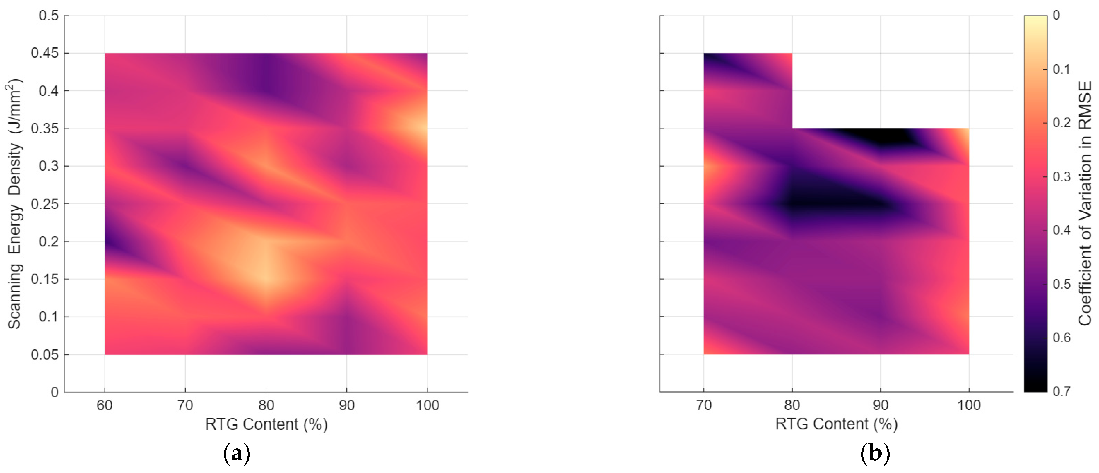
The Coefficients of Variation (CoV) in the RMSE measurements of both detected edge linear regressions for each specimen, across the triplicated specimens, are plotted with respect to SED and substrate RTG content and grouped by SiO2 additive granularity. The results are shown in Figure 7.
The RMSE data for the Substrate with 20 nm SiO2 additive at 0.40 J/mm2 SED were not collected successfully and are therefore omitted in Figure 6 and Figure 7.

3.2. Demonstrations of Intralayer Fusion

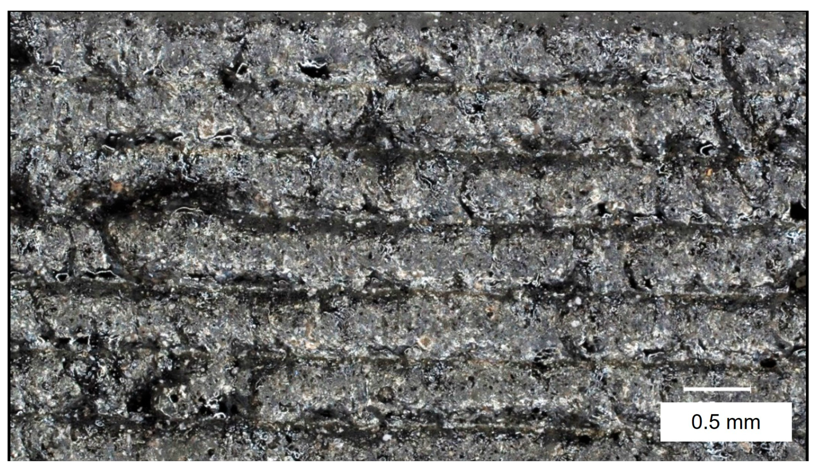
Optical images demonstrating the results of the intralayer fusion experiments were also recorded using the Keyence VHX-7000 optical microscope, as shown in Figure 8. The successful demonstration of intralayer fusion (Figure 7 and Figure 8) proves that a 5 W diode laser, typically considered insufficient, can induce remelting and bonding in this specific ceramic system. This finding opens a new path for ultra-low-cost ceramic AM, a field that has seen little exploration compared to the development of low-cost polymer and metal printers.
To assess the characteristics of the intralayer fusion, a depth composition image was recorded. This data includes a point cloud scan of the region. The results of the depth composition measurements are shown as a heightmap in Figure 9.
By observing the continuity of the surface profile, it is concluded that previously scanned material liquefied and fused with the adjacent melt pool. This demonstrates that remelting and intralayer bonding is viable in this process configuration.

3.3. Observed Structural Defects

While intralayer fusion was achieved, significant defects were observed. At SEDs above 0.45 J/mm2, we observed melt pool instability and stagnation, consistent with the ‘balling effect’. Furthermore, in 2D square specimens, significant thermal warping and cracking were observed, especially in specimens with high total energy input. We expect that these defects can be significantly minimized by providing appropriate bed adhesion, which allows the part to deform under thermal stresses.

4. Conclusions

This study successfully demonstrated the feasibility of using a low-cost, 5W diode laser LPBF system to process an impure RTG. Optical microscopy and image processing methods were employed to measure the width and uniformity of fabricated beads for a range of substrate compositions and SEDs. Consistent with the literature, a trend was observed in which the fabricated bead width increases with increasing SED. Trends in the uniformity of fabricated beads, with respect to changes in the tested process parameters, were not immediately apparent or significant. The ability to perform intralayer fusion was also demonstrated. This further indicated the viability of three-dimensional, dense fabrication using ceramic substrates.
The use of RTG as a feedstock is a key aspect of this low-cost approach. While conventional ceramic AM utilizes high-purity, spherical powders (e.g., Al2O3, ZrO2) to ensure predictable melt pool behavior, RTG is inexpensive and widely available. Our findings showed that this non-ideal feedstock can still be successfully densified. However, this impurity likely contributed to melt pool instabilities and non-uniformity, defining a processing boundary distinct from that of high-purity powders. Although this study was limited to one- and two-dimensional fabrication experiments due to the lack of bed adhesion, the demonstrations show promise for the fabrication of densified ceramic parts at a cost accessible to consumers. Further research is necessary to determine whether cracking and warping can be sufficiently mitigated through enhanced bed adhesion and improved process control. Various mixtures of ceramic powder are available at a low cost, generally in the form of RTG, and experimentation is necessary to determine if alternative feedstocks are appropriate.

Author Contributions

Conceptualization, S.K.B. and Y.L.; methodology, Y.L.; formal analysis, S.K.B.; writing—original draft preparation, S.K.B.; writing—review and editing, Y.L. All authors have read and agreed to the published version of the manuscript.

Funding

Financial support was provided by the University of Oklahoma Libraries’ Open Access Fund.

Institutional Review Board Statement

Not applicable.

Informed Consent Statement

Not applicable.

Data Availability Statement

The raw data supporting the conclusions of this article will be made available by the corresponding author on request.

Acknowledgments

Microscopy data collection was performed at the Samuel Roberts Noble Microscopy Laboratory at the University of Oklahoma.

Conflicts of Interest

The authors declare no conflicts of interest.

Abbreviations

The following abbreviations are used in this manuscript:
LPBFLaser Powder Bed Fusion
SEDScanning Energy Density
RMSERoot Mean Square Error
CoVCoefficient of Variation

Appendix A

Table A1. Average NFBWs and RMSEs for Each Substrate Mixture and SED.
Mixture NameSED   ×   10 1   ( J m m 2 ) Mean NFBW   ×   10 1 Mean RMSE   ×   1 0 2
100RTG[0.5, 1.0, 1.5, 2.0, 2.5, 3.0, 3.5, 4.0, 4.5][5.0, 6.4, 6.6, 6.7, 6.9, 7.4, 8.0, 8.7, 9.2] [1.9, 1.7, 1.8, 1.5, 1.9, 2.0, 2.3, 2.3, 2.3]
90RTG_A[5.6, 6.1, 5.7, 6.6, 6.6, 7.2, 7.5, 7.5, 8.5][2.1, 2.6, 2.5, 2.7, 3.1, 2.4, 3.2, 2.7, 3.0]
90RTG_B[5.6, 5.7, 6.2, 6.2, 6.5, 8.1, 7.6, 8.2, 8.8][2.8, 3.1, 3.3, 3.1, 3.7, 2.8, 3.7, Na, 2.9]
80RTG_A[5.2, 5.3, 5.9, 6.1, 7.1, 6.8, 7.3, 7.4, 7.7][3.4, 4.1, 3.1, 5.5, 5.4, 4.4, 4.0, 3.9, 3.8]
80RTG_B[5.5, 6.0, 6.1, 7.0, 6.9, 7.2, 8.1, 8.4, 9.6][3.2, 3.2, 2.3, 2.6, 3.0, 3.3, 3.6, 3.2, 3.8]
70RTG_A[5.2, 5.7, 5.7, 5.8, 6.0, 6.7, 7.8, 8.2, 8.5][2.5, 2.9, 2.9, 3.3, 4.0, 3.8, 3.1, 3.1, 2.8]
70RTG_B[5.9, 5.9, 6.0, 6.9, 6.8, 7.3, 7.9, 8.2, 9.0][2.5, 2.2, 2.6, 2.8, 2.9, 2.8, 3.0, 2.4, 3.5]
60RTG_A[5.1, 5.5, 5.9, 6.1, 6.7, 7.4, 7.9, 8.0, 8.4][3.0, 2.9, 3.3, 3.4, 3.1, 3.7, 4.6, 3.8, 4.3]

References

  1. Otitoju, T.A.; Okoye, P.U.; Chen, G.; Li, Y.; Okoye, M.O.; Li, S. Advanced ceramic components: Materials, fabrication, and applications. J. Ind. Eng. Chem. 2020, 85, 34–65. [Google Scholar] [CrossRef]
  2. Belmonte, M. Advanced ceramic materials for high temperature applications. Adv. Eng. Mater. 2006, 8, 693–703. [Google Scholar] [CrossRef]
  3. Randhawa, K.S. A state-of-the-art review on advanced ceramic materials: Fabrication, characteristics, applications, and wettability. Pigment Resin Technol. 2024, 53, 768–785. [Google Scholar] [CrossRef]
  4. Ullah, A.; Shah, M.; Ali, Z.; Asami, K.; Ur Rehman, A.; Emmelmann, C. Additive manufacturing of ceramics via the laser powder bed fusion process. Int. J. Appl. Ceram. Technol. 2025, 22, e15087. [Google Scholar] [CrossRef]
  5. Karabulut, Y.; Ünal, R. Additive manufacturing of ceramic particle-reinforced aluminum—Based metal matrix composites: A review. J. Mater. Sci. 2022, 57, 19212–19242. [Google Scholar] [CrossRef]
  6. Wang, J.-C.; Dommati, H.; Hsieh, S.-J. Review of additive manufacturing methods for high-performance ceramic materials. Int. J. Adv. Manuf. Technol. 2019, 103, 2627–2647. [Google Scholar] [CrossRef]
  7. Villa, R.; Billings, C.; Siddique, Z.; Liu, Y. A Look at Two Nuisance Process Hurdles Encountered by New Laser Powder Bed Fusion Operators Printing Ti6Al4V. J. Mater. Eng. Perform. 2025, 34, 21941–21948. [Google Scholar] [CrossRef]
  8. Lamm, B.W.; Karakoc, O.; Mao, K.; Koyanagi, T.; Liu, J.; Katoh, Y. Phase separation during the direct powder bed fusion of SiC. Int. J. Appl. Ceram. Technol. 2024, 21, 1722–1734. [Google Scholar] [CrossRef]
  9. Qiao, L.; Gan, Y.; Wu, Y.; Zhai, M.; Wang, M.; Li, R.; Li, T.; Zhang, X.; Chang, T. Preparation and characterization of corrosion-resistant FeCrMoNiCuBSiC metallic glass coating by HVOF spraying. Surf. Coat. Technol. 2025, 513, 132507. [Google Scholar] [CrossRef]
  10. De Leon, E.; Riensche, A.; Bevans, B.D.; Billings, C.; Siddique, Z.; Liu, Y. A Review of Modeling, Simulation, and Process Qualification of Additively Manufactured Metal Components via the Laser Powder Bed Fusion Method. J. Manuf. Mater. Process. 2025, 9, 22. [Google Scholar] [CrossRef]
  11. Liu, R.; Yang, H. Multimodal probabilistic modeling of melt pool geometry variations in additive manufacturing. Addit. Manuf. 2023, 61, 103375. [Google Scholar] [CrossRef]
  12. Zhang, M.; Fang, B.; Fan, L. Optimizing powder morphology and scanning strategies to enhance shape accuracy in L-PBF alumina ceramic formation. Ceram. Int. 2025, 51, 8042–8053. [Google Scholar] [CrossRef]
  13. Wang, W.; Liang, S.Y. Prediction of molten pool height, contact angle, and balling occurrence in laser powder bed fusion. Int. J. Adv. Manuf. Technol. 2022, 119, 6193–6202. [Google Scholar] [CrossRef]
  14. García-Rodríguez, S.; Bedmar, J.; Abu-warda, N.; Torres, B.; Rams, J. Microstructure and corrosion behavior of 316L stainless steel lattice and bulk parts manufactured by LPBF using fiber and CO2 lasers. Mater. Des. 2024, 244, 113214. [Google Scholar] [CrossRef]
  15. Shen, Z.; Su, H.; Yu, M.; Yang, P.; Guo, Y.; Cao, Y.; Jiang, H.; Li, X.; Dong, D.; Zhang, Z. Synergistic dual-scale laser beams for fabricating high-temperature eutectic ceramic coatings with nano microstructures via LPBF. J. Mater. Sci. Technol. 2025, 234, 292–306. [Google Scholar] [CrossRef]
  16. Seyfarth, B.; Schade, L.; Matthäus, G.; Ullsperger, T.; Heidler, N.; Hilpert, E.; Nolte, S. Laser powder bed fusion of glass: A comparative study between CO2 lasers and ultrashort laser pulses. In Laser 3D Manufacturing VII; SPIE: San Francisco, CA, USA, 2020; pp. 87–92. [Google Scholar]
  17. Liu, K.; Wu, T.; Bourell, D.L.; Tan, Y.; Wang, J.; He, M.; Sun, H.; Shi, Y.; Chen, J. Laser additive manufacturing and homogeneous densification of complicated shape SiC ceramic parts. Ceram. Int. 2018, 44, 21067–21075. [Google Scholar] [CrossRef]
  18. Zhang, B.; Li, Y.; Bai, Q. Defect formation mechanisms in selective laser melting: A review. Chin. J. Mech. Eng. 2017, 30, 515–527. [Google Scholar] [CrossRef]
  19. Pfeiffer, S.; Florio, K.; Puccio, D.; Grasso, M.; Colosimo, B.M.; Aneziris, C.G.; Wegener, K.; Graule, T. Direct laser additive manufacturing of high performance oxide ceramics: A state-of-the-art review. J. Eur. Ceram. Soc. 2021, 41, 6087–6114. [Google Scholar] [CrossRef]
  20. Zhao, X.; Wang, T. Laser powder bed fusion of powder material: A review. 3D Print. Addit. Manuf. 2023, 10, 1439–1454. [Google Scholar] [CrossRef] [PubMed]
Figure 1. Developed LPBF 3D printing system for AM of ceramic materials.
Applsci 15 12091 g001
Figure 2. Example of image processing results for recapturing raw data of the detected edge points.
Applsci 15 12091 g002
Figure 3. Bland–Altman Analysis plot showing the agreement between the two bead width measurement methods.
Applsci 15 12091 g003
Figure 4. NFBW measurements with varying SED and substrate RTG Content (a) Substrate with 57.8 μm SiO2 additive; (b) Substrate with 20 nm SiO2 additive.
Applsci 15 12091 g004
Figure 5. Coefficient of Variation in NFBW measurements with varying SED and Substrate RTG Content (a) Substrate with 57.8 μm SiO2 additive; (b) Substrate with 20 nm SiO2 additive.
Applsci 15 12091 g005
Figure 6. RMSE of detected edge linear regression with varying SED and Substrate RTG Content (a) Substrate with 57.8 μm SiO2 additive; (b) Substrate with 20 nm SiO2 additive.
Applsci 15 12091 g006
Figure 7. Coefficient of Variation in RMSE of detected edge linear regression with varying SED and Substrate RTG content (a) Substrate with 57.8 μm SiO2 additive; (b) Substrate with 20 nm SiO2 additive.
Applsci 15 12091 g007
Figure 8. Optical image of intralayer fusion in a specimen fabricated with 100 vol% RTG substrate, 0.45 J/mm2 SED, and 0.35 mm hatch spacing.
Applsci 15 12091 g008
Figure 9. Optical image and heightmap of parallel bonding region in specimen fabricated with 100 vol% RTG substrate, 0.45 J/mm2 SED, and 0.35 mm hatch spacing. (a) Optical image of region, (b) depth chart of region.
Applsci 15 12091 g009
Table 1. Powder Feedstocks Used in Experiment Substrates.
SupplierChemical Makeup
(Purity)
ModelAverage Particle
Diameter
SackOrange (Shenzhen, China)Black Fused Alumina (N.L.)Step-3 500 Grit Silicon Carbide Rock Tumbler Grit50 μm
LFA Machines (Fort Worth, TX, USA)SiO2 (99.9%)Silicon Dioxide
Anticaking Agent
20 nm
Chemsavers (Bluefield, VA, USA)SiO2 (99.5%)Silicon Dioxide (Silica), Powder—325 Mesh57.8 μm
Table 2. List of Substrate Mixtures and Respective Formulations.
Mixture NameRTG Content (vol%)57.8 μm SiO2 Content (vol%)20 nm SiO2 Content (vol%)
100RTG100N/AN/A
90RTG_A9010N/A
90RTG_B90N/A10
80RTG_A8020N/A
80RTG_B80N/A20
70RTG_A7030N/A
70RTG_B70N/A30
60RTG_A6040N/A
Disclaimer/Publisher’s Note: The statements, opinions and data contained in all publications are solely those of the individual author(s) and contributor(s) and not of MDPI and/or the editor(s). MDPI and/or the editor(s) disclaim responsibility for any injury to people or property resulting from any ideas, methods, instructions or products referred to in the content.