1. Introduction
Heat treatment is an important step in the production of metal parts and components because it improves the mechanical and physical properties of the material. There are two types of heat treatment: laser heat treatment and classical heat treatment. Laser heat treatment is the process of heating the surface of a material using a focused beam of laser energy. The precision of this heat treatment allows for the selective heating of specific regions within an object of interest. Applications that require precise control over the heat energy input, like the aerospace and medical industries, frequently employ laser heat treatment.
Traditional heat treatment methods, on the other hand, entail heating a material to a specific temperature and then cooling it at a regulated rate using conventional heat sources, such as dedicated furnaces. Annealing, quenching, tempering, and normalizing are examples of classical heat treatment procedures. The manufacturing industry widely uses these technologies to enhance the mechanical qualities of materials, including mechanical strength, hardness, wear resistance, or toughness.
Low-temperature treatment is the process of cooling materials to extremely low temperatures, often below −50 °C (in the case of cryogeny, the temperature is below −150 °C), to improve their physical and mechanical qualities. This process promotes the release of internal tensions in the material and can cause microstructural changes, which contribute to an increase in material properties.
Heat treatment and low-temperature cooling entail heating and cooling material in alternating cycles. This technique can have a variety of effects on the material, depending on its composition and qualities. Alternating heating and cooling cycles, for instance, can help produce a material with optimized mechanical properties, greater dimensional stability, and machinability. Studies [
1,
2,
3,
4,
5] frequently employ cryogenic treatment in conjunction with heat treatment procedures to enhance the properties of metals and alloys. Following the initial heat treatment process, the material may still have residual stresses, which might reduce its characteristics and durability. Cryogenic treatment can assist the release of these tensions and cause favorable modifications to the material’s microstructure. Overall, cryogenic cooling after heat treatment can provide various benefits, the most significant of which are that it
Improves mechanical qualities, including hardness and wear resistance.
Increases dimensional stability and durability.
Improves resistance to corrosion and other chemical phenomena.
Enhances fatigue resistance and overall performance.
To summarize, the symbiosis of heat treatment with cryogenic cooling can have a significant impact on the overall performance of a material that is subjected to such an approach by obtaining superior properties for this material, making it more suitable for a wide range of critical applications such as aerospace, medical, or automotive.
Based on these basic ideas, we think that university research needs to create an independent mechatronic platform so that undergraduate, graduate, and doctoral students can safely study what happens to tiny mechanical parts made of different materials when these heat treatments are used alone or together.
Laser equipment can have a variety of impacts [
6]. Since the eye is particularly vulnerable to laser light, we can discuss ocular hazards. Many reported injuries involve the eye and can be caused by direct beams, mirror reflections from other equipment, or beam reflections off the skin. Laser-generated airborne pollutants, such as chemicals (particularly smoke) and material nanoparticles, pose a significant risk as well. Class 4 lasers are known to present fire hazards, which is another area of worry for laser users. Often, laser users face two types of fire hazards: flash fires, which happen when the laser beam encounters flammable material, and electrical fires within the laser, occasionally stemming from faulty wiring.
Human hazards from low temperatures and cryogenic equipment can include skin burns, over-pressurization, asphyxiation, respiratory irritation, fire, and explosion, as well as direct contact with the material surface (skin stuck to cold surfaces, skin burns) or leaks, sprays, or spills of the cryogenic fluids [
7,
8].
We suggest the use of an autonomous stand that may be operated remotely safely with the objective of reducing these harmful and undesirable impacts, particularly because we are discussing the issue of young students that fail to comply with the safety regulations or pay close attention to the teacher.
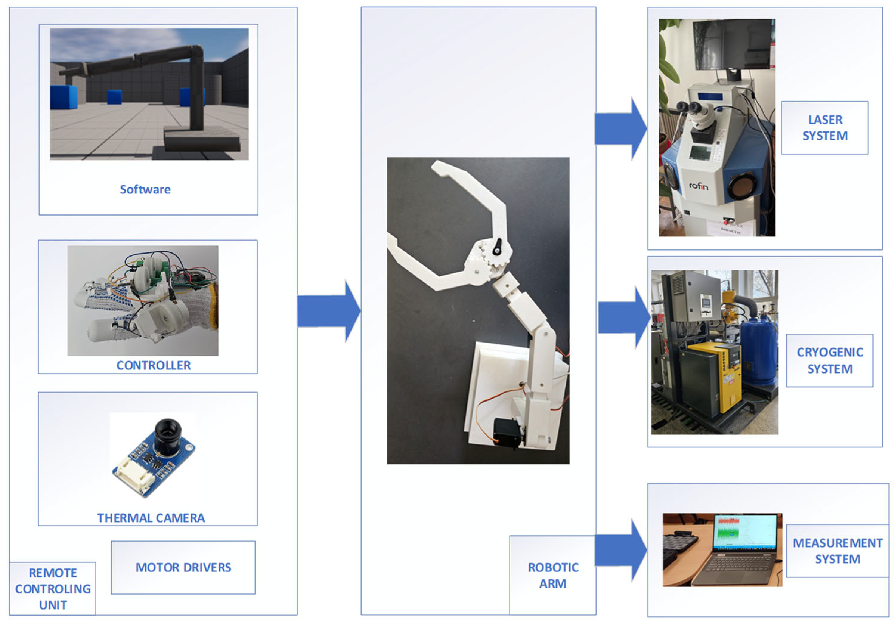
Figure 1 shows a model of the suggested educational testing mechatronic platform, starting from a robotic arm with a gripper, which has the role of manipulating the treated specimens between and after the thermal treatments. A VR remote control has the following advantages [
9,
10]: it offers enhanced operator safety because the user is not in the proximity of any hazardous environment, reducing exposure to physical risks; intuitive and immersive control because VR models enhance the user’s spatial perception and hand–eye coordination, helping operators execute complex tasks more intuitively than traditional interfaces; it offers flexible training and skill adaptation, and the users can learn and adapt faster in VR environments, speeding up deployment and improving task outcomes; and it offers real-time environment visualization, improving awareness. This type of control also has some disadvantages; the most important is that the speed of the robotic arm is slow because the inherent latency and communication delays can induce user discomfort and fatigue, which affects operator performance. Reliability is reduced because of the signal loss, sensor tracking failures, and hardware complexity, which create challenges for consistent and accurate robot control. Usually, haptic devices have limited tactile feedback [
11], reducing performance in manipulation tasks. Our proposed glove provides this type of feedback to each finger used for control.
The mechanical part of the robotic system prototype was designed based on the analysis of constructive and technological solutions for different applications [
12,
13,
14,
15,
16,
17,
18,
19] to obtain an optimal and accessible variant. Particular importance for the manipulation of specific objects is represented by the prehension part (gripper) [
20,
21,
22,
23,
24,
25,
26,
27,
28,
29] of the robot and the related materials, which will be analyzed in future studies. Regarding the laser equipment and considering the final goal of the concept, it can be used as laser equipment for heat treatment or even for micro-welding (for precise laser processing) with the adjustment of power, pulse, optics, or other processing parameters with a solid active medium Nd: YAG and a wavelength of 1.06 µm. Regarding the second heat treatment equipment, a classic installation with a cryogenic atmosphere (liquid nitrogen) can be used in the first phase, and the robotic arm will have the role of manipulating the specimens between and after the thermal processes. Although there are recent studies in the literature outlining the beneficial effects of combined thermal treatments (heat treatment and cryogenic) on material properties [
1,
2,
3,
4,
5], their handling between treatments is not approached in detail. The novelty of the paper refers to the reconfigurability and rapid adaptability/customization of the robotic arm depending on the geometry of the specimen that will need to be manipulated and the concept itself of a mechatronic platform for this purpose, which can be expanded with motorized platforms for bringing parts into the working area of the robotic arm (between the equipment), considering that in the first phase the robotic arm, due to the materials used, will not be able to operate directly in aggressive thermal environments. Additive manufacturing is the best option for adaptability/rapid prototyping and replacement of subassemblies, depending on the required object. But it has the potential to produce components through specific technologies, even for direct manipulation, including in aggressive environments. In addition, the benefit of the implementation of this concept lies in interdisciplinary educational purposes, including diversified branches like robotics, mechatronics, control engineering, material science, manufacturing technologies, and so on.
The educational mechatronic platform comprises one robotic positioning system that has two roles. The first is to transport the object from the storage to the laser thermal processing system and back, and the second is to transport the object from the storage to the low-temperature thermal processing system and finally to the measurement system. A controller remotely controls the robotic positioning system, using a glove and a VR environment. This system uses a thermal camera to measure the part’s temperature and determine the optimal moment to handle the mechanical part. This ensures the gripper is protected and can operate for a longer period.
Therefore, the paper aims to present a concept of a mechatronic platform applied to the manipulation of structures during thermal treatments, namely laser thermal treatment, followed by cooling at low temperatures. Namely, the main subsystems that make up the mechatronic platform are presented with an emphasis on the robotic positioning system, the manufacturing of the robotic positioning system, and the glove using 3D printing, and to implement software using VR that allows the user to interact with the 3D model and with the robotic positioning system. Also, important technological aspects are discussed for the manufacturing of the mechanical structure of the prototype for further development, testing, and optimization of the system. The methodology of the work is illustrated in
Figure 2.
2. Materials and Methods
2.1. Robotic Positioning Systems
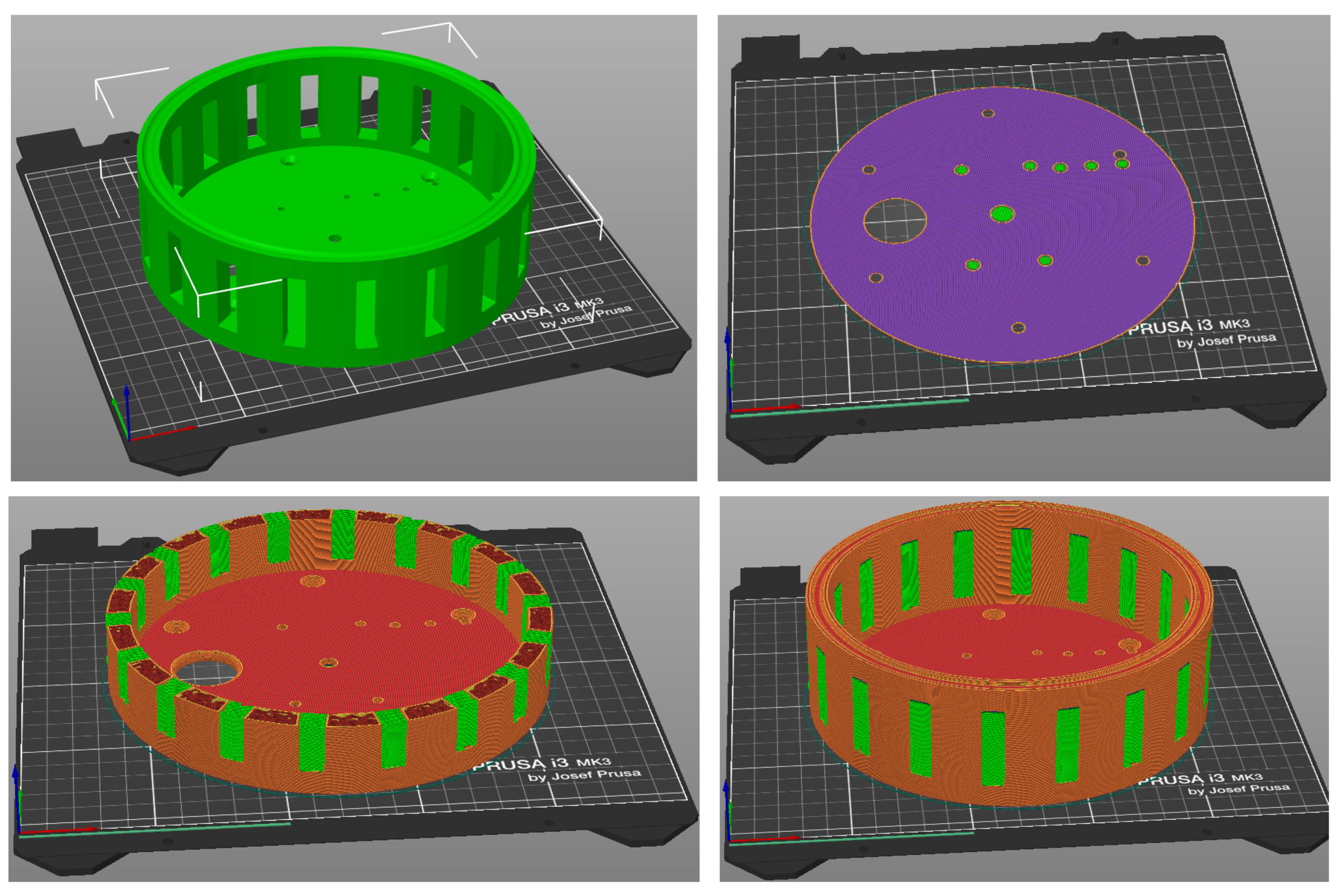
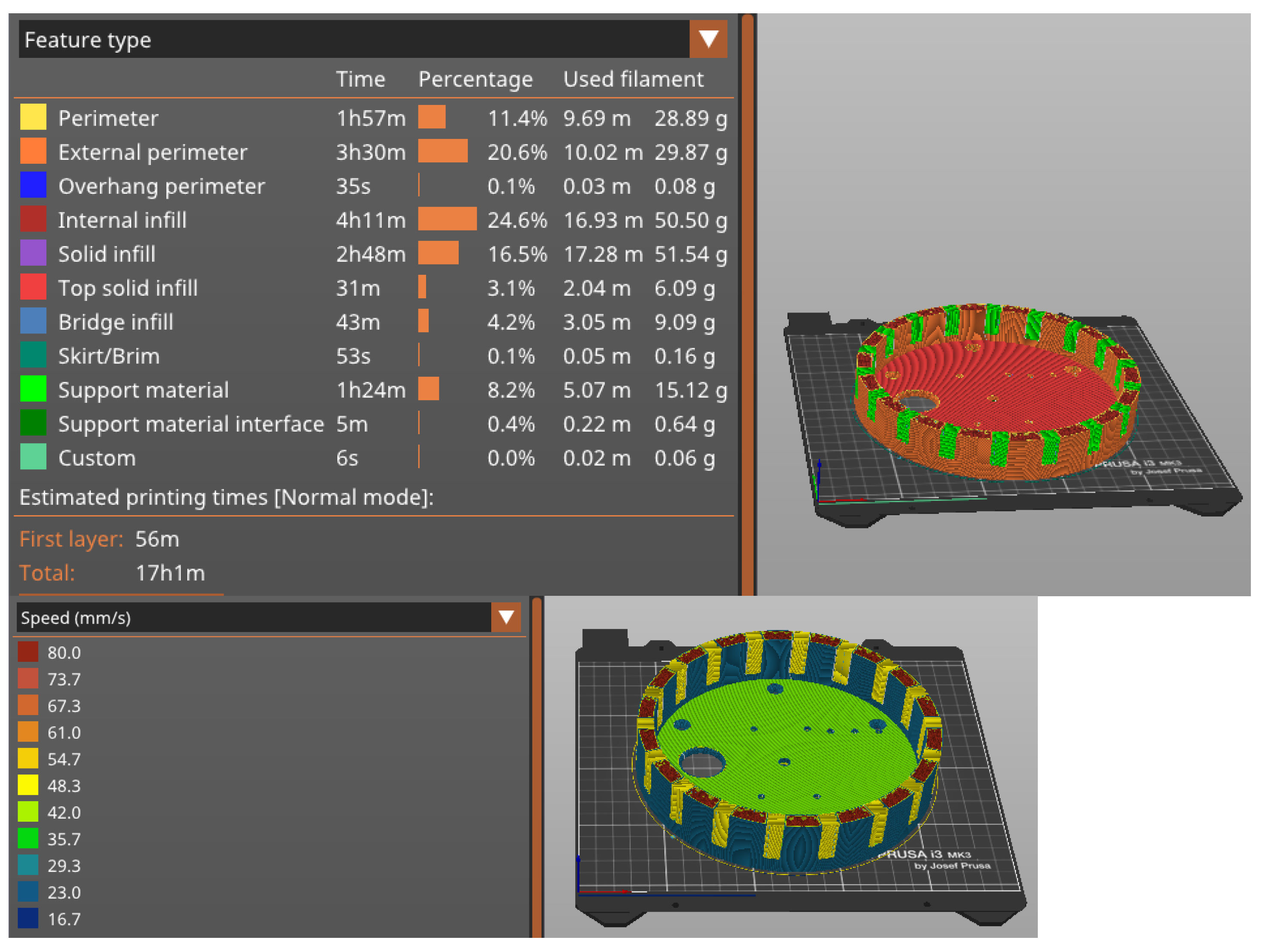
The robotic positioning system is the key component of the mechatronic platform. The primary focus is on simplifying the creation process through additive manufacturing, minimizing the number of components, minimizing the amount of material used in production, and implementing a simple control system.
Because we use a robotic positioning system that can have different dimensions and shapes, it is important to apply the command and control of the robotic arm without changing the controlling unit.
In this work, we present a robotic positioning system, which is actually a reprogrammable multifunctional manipulator designed to handle materials, components, tools, or specialized devices using programmed movements. This enables them to perform a variety of tasks at a high-performance level and to gather information from the work environment to facilitate movement. They feature three simple articulated arm rotations, resembling articulated toroidal, revolution, or anthropomorphic robot arms.
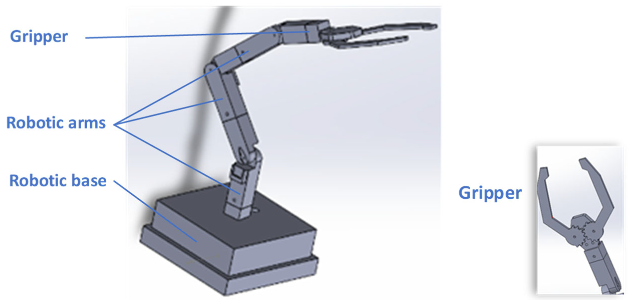
The robotic positioning system has 4 degrees of freedom: one rotation of the fixed base, three rotations of the arms, and one displacement of the gripper fingers—
Figure 3.
The fixed base contains the stepper motor, which is used for the frame’s rotational movement, as well as components required for this movement, such as the gear wheel, which is positioned on the axis of the stepper motor, and the ring gear, which is fastened on the inner side surface of the frame and is engaged by the gear wheel mounted on the shaft of the stepper motor, in support. It also contains a central shaft, on which is placed a radial bearing that allows the frame to rotate and is housed in a bearing holder. Additionally, the fixed base incorporates two raceways for bearing balls, each secured in a ring; this assembly serves as an axial bearing, supporting the arm’s weight. Between the upper section of the frame and the bottom half, there is an axial bearing supporting the weight of the robotic positioning system.
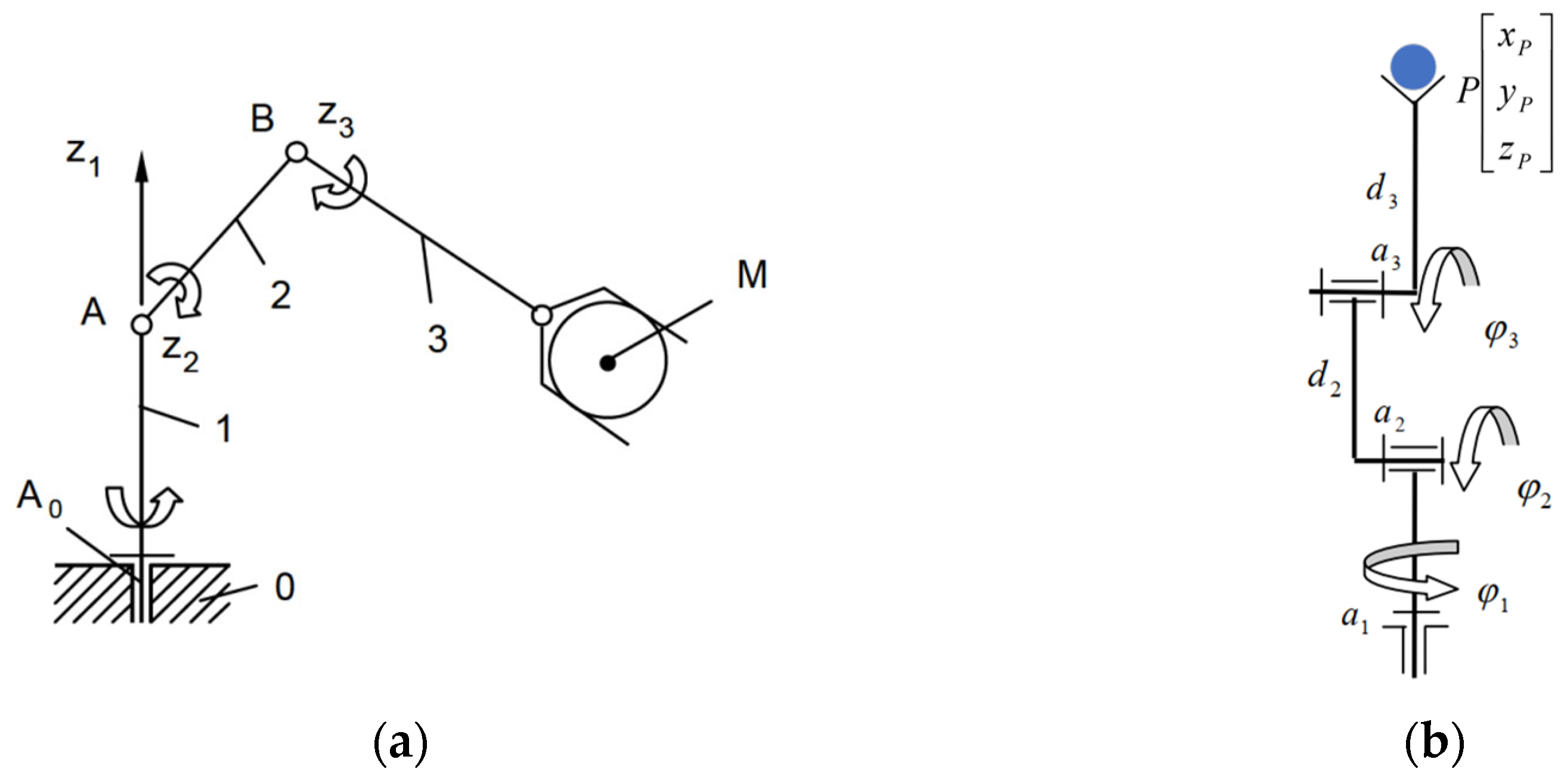
The robotic arm, in the first configuration, used in the testing has three rotations, and thus, the kinematic scheme and the control scheme are similar. According to
Figure 4, element 1 is a column, element 2 is an arm, and element 3 is a forearm. The rotations are in rotational kinematic couplings A0 (1, 2), A (1, 2), and B (2, 3), and the whole mechanism has 3 degrees of freedom. This configuration is not limited, and the robot can have multiple elements structured in a chain from the base to the gripper.
In order to control the robot, we need to know the position of the gripper in space, and thus, we must apply the inverse kinematics of the mechanism of the robotic arm. This involves knowing the instantaneous position of the tracer point P on an imposed trajectory and determining the position functions of the active elements. The equations of the position of point P are defined, considering a Cartesian coordinate system, according to the notations in
Figure 4b:
To solve the system of equations more easily, we can consider a specific case where a
2 = a
3, and using the first two equations of the system (1), angle φ
1 can be obtained from the equation
The system of Equation (1) can be simplified by using Equation (2):
From Equation (3) the angle
can be eliminated, and the value of
can be obtained:
The coefficients A, B and C used in Equation (4) are defined by equations:
Knowing angles φ
1 and φ
2, the angle φ
3 is obtained using the equation
Because a robotic positioning system that can have different dimensions and shapes is used, the problem of inverse kinematics accuracy is a very complex issue. Inverse kinematics is the process of computing joint angles so that the robotic arm’s gripper is at a specific location and orientation. Its accuracy shows the error between the desired and the obtained position and orientation after moving the joints according to the inverse kinematic solver. From a single-dimension perspective, it can be said that the accuracy is
where ε is the accuracy, x
desired is the position that the robotic arm’s gripper should have, and x
obtained is the value of the measured position after the arm moved its gripper. It should be noticed that this is an oversimplified example because the position in both VR and the real world should have three Cartesian coordinates and three angle values to completely define the position and the orientation of the end-effector.
Various methods available in the literature can be used to assess the inverse kinematics accuracy, such as the one described by Zhang [
30]. Other methods could include a direct measuring approach or image processing from two cameras, which could be developed into a closed feedback loop.
There are several factors that influence inverse kinematics accuracy. Among them, one can enumerate model accuracy, numerical solving precision, algorithm, joint resolution (the physical precision of actuators or encoders), signal noise, sensor drift, mechanical tolerances, backlash, and compliance in gears or links, and thermal expansion. The material used to manufacture the mechanical components of the presented model was chosen for its low cost and ease of prototyping. Therefore, their mechanical properties and stability vary.
Being an educational system with a variable number of modules, and due to the materials used, calculating accuracy is a task too difficult to present in this article, which focuses on the structure and control of the system. However, its determination can be used as an exercise for students by giving a higher or lower degree of complexity depending on their training and the objective of the application.
The next step after validating the control software of the robotic arm, the hardware structure of the VR glove, and the correlation between the VR and reality will be to manufacture robotic modules made from reliable materials that will greatly increase the inverse kinematics accuracy.
However, robotic arms have some constraints related to the position and mechanical configuration of the cryogenic system and the workpiece positioning system. They have a shape similar to a parallelepiped with a maximum weight of 200 g and with the following maximum dimensions: length 80 mm, width 55 mm, and height 6 mm. The distance between the axis of rotation of the arm from the cryogenic system handling system is 300 mm, and from the sample positioning system of the laser processing system, it is 350 mm. The robotic arm needs to rotate by 198 degrees, and the height is not dimensionally conditioned. Also, the orientation and correction of the position of the machined part is done at the gripper level, which will be presented in another article. For the reasons listed, it follows that the robotic arm in a minimum configuration (the one presented in this article) must ensure a movement between the two systems under the conditions of a positioning error of a maximum of 4 mm. The manufacturing does not insert any constraints related to speed and repeatability, which are parameters that depend on user experience.
2.2. System for Hapting Control of the Robotic Arm
The gloves employed in virtual reality are interactive devices that enhance the realism and immersion of VR experiences. They accomplish this by incorporating haptic technologies that enhance user interaction with elements of the virtual environment. These gloves enable the visual description of hand movements and gestures in a virtual environment, transmit a range of tactile sensations from fine to coarse, simulate the weight and solidity of virtual objects, allow the perception of object shape and texture on virtual surfaces, and replicate the thermal sensation of objects within the virtual domain. VR gloves seek to emulate human interaction in the physical realm with utmost precision, converting it into a digital format. The primary function of VR gloves is twofold: to capture movement by transmitting location, orientation, and hand motions in real time, and to deliver sensory input using integrated actuators.
Alternative manual input methods encompass video cameras that track finger motions without the need for additional controllers, as well as portable haptic devices that offer accurate tactile feedback. Representations of products and technologies: The built-in hand tracking technology of Meta Quest 2 (Meta Platforms, Inc., Menlo Park, USA) utilizes the VR headset’s cameras to monitor hand movements, facilitating interaction without the need for controllers. After analyzing the current market solutions and their attributes, a decision was made to develop a virtual reality glove capable of detecting hand orientation, finger positioning, and delivering force feedback. The proposed method anticipates an optimal balance of cost, complexity, and usefulness, designed for instructional, simulation, and intuitive interface applications in virtual worlds.
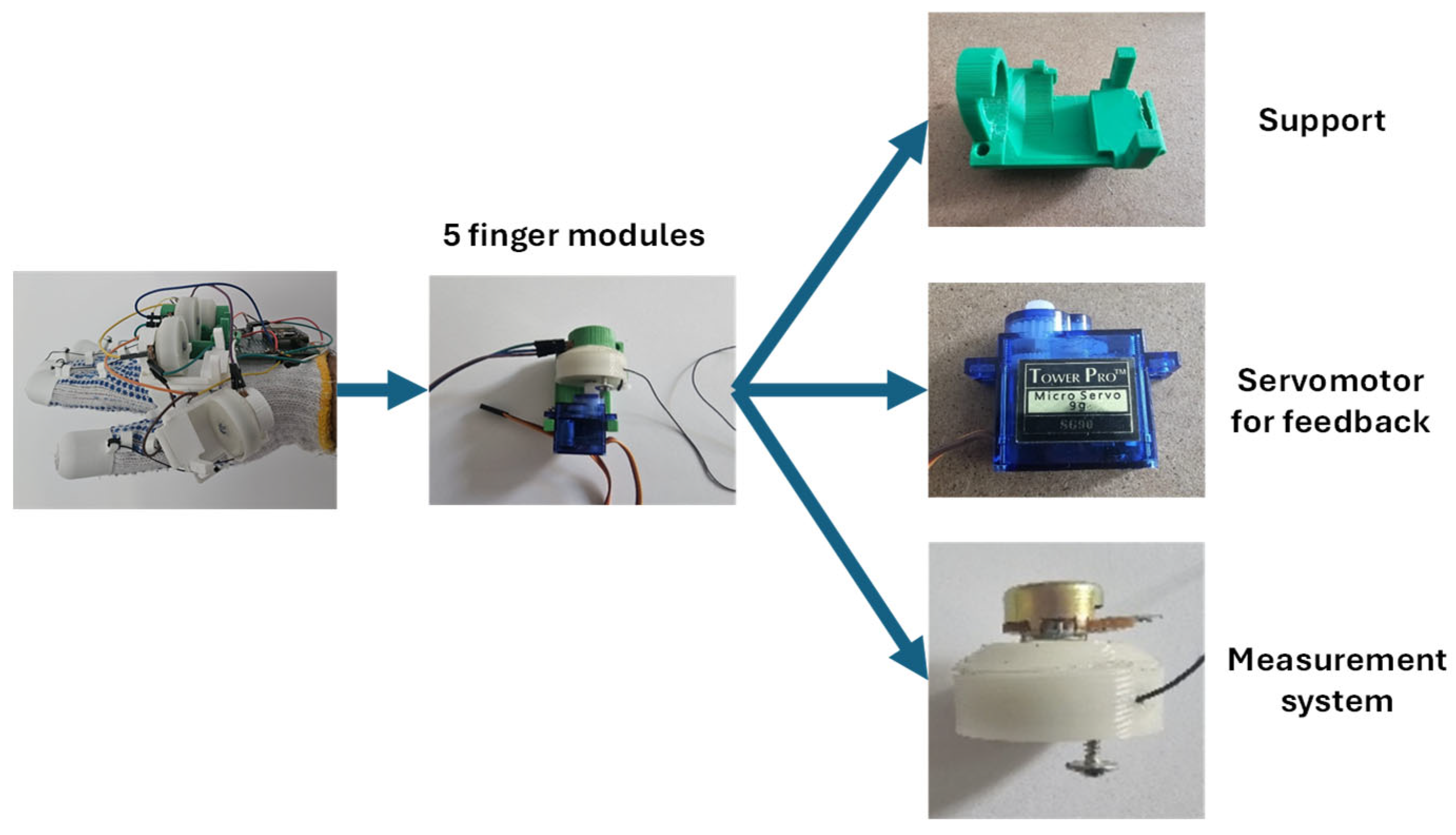
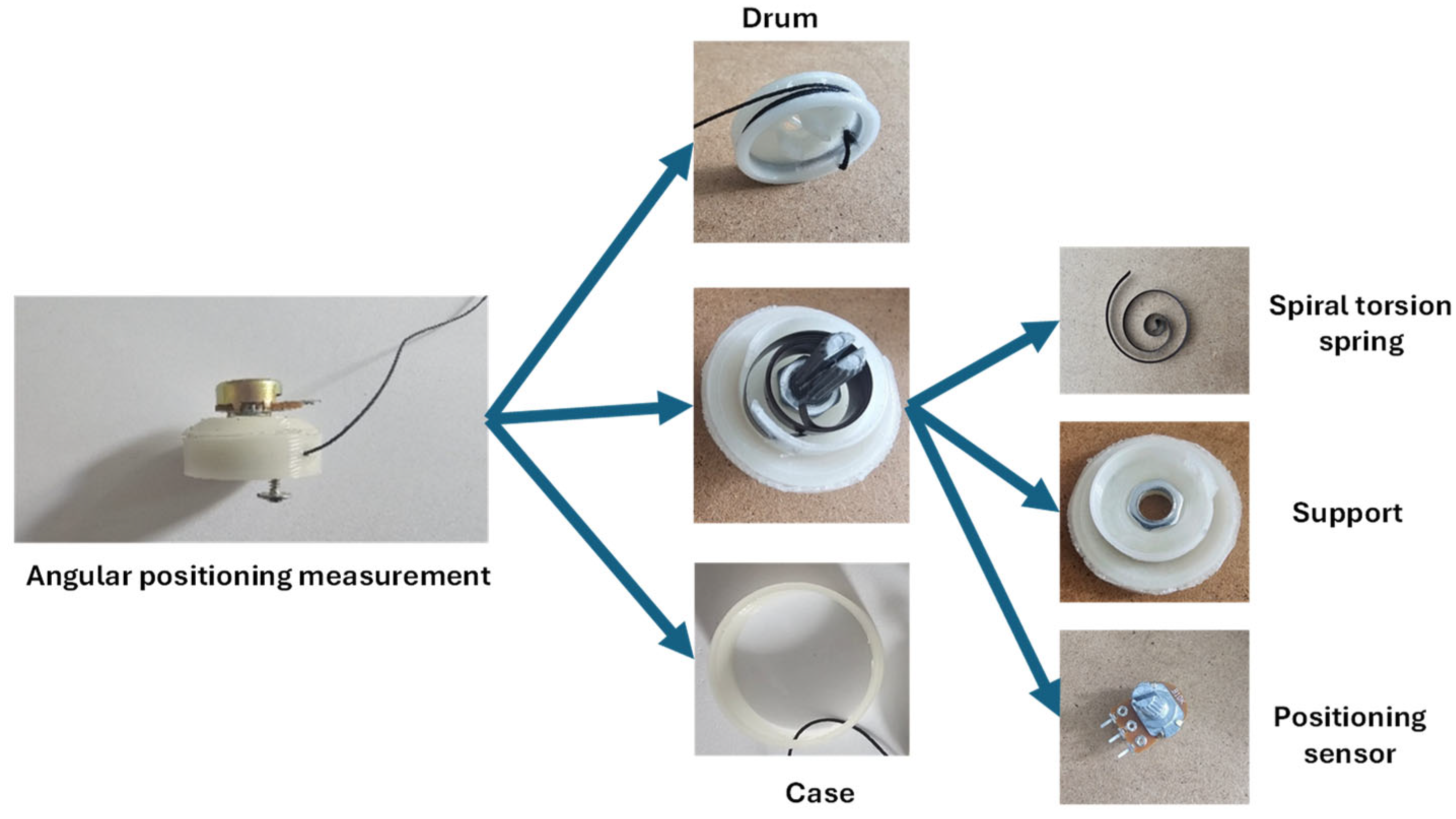
The assembly’s 3D modeling was performed in SolidWorks (version: 2023), providing a clear visualization of the arrangement of system components and confirming their geometric compatibility. An assembly was created for each digit. It consists of the support attached to the hand and the subassembly that restricts finger movement. The finger movement tracking and restricting subassembly consists of a bracket that supports the additional components and can be attached to the base bracket via a sliding mechanism; an SG 90 servo motor (Tower Pro Pte Ltd., Singapore) that controls finger movement; a resistive spinning sensor for detecting finger position; a drum onto which the wires connected to the fingers are coiled; a supporting component that connects the resistive rotary sensor, the internal spiral spring, the drum, and a casing that secures to the purple element; and a spiral spring.
The hand support affixed to the glove is illustrated in
Figure 5 and possesses the following attributes: the device features a slender base that allows for folding and conforms to the hand’s shape; it comprises six platforms housing five subassemblies, a MPU6050 sensor (TDK InvenSense, San Jose, USA), and a microcontroller serving as the central control system. At either end of the structure, two elongated bores facilitate the attachment of an elastic band to secure it to the glove, along with a bracket that connects the base and components to monitor and restrict finger movement. The bracket serves to support and secure the electrical and mechanical components. The assembly comprises a platform for the servo motor, a substantial bore for the insertion of the resistive rotating sensor’s base, and a sliding mechanism for its attachment to the base support.
The finger movement tracking and limiting subassembly comprises a finger position measurement subassembly that utilizes a retractable key fob. The threads attached to the fingers are coiled on a drum that is affixed directly to the shaft of the resistive rotating sensor. When the finger exerts tension on the wire, the drum rotates in conjunction with the resistive spinning sensor shaft. This subassembly includes a component that links the resistive rotating sensor to the spiral arc. It possesses an interior hexagonal configuration that enables the resistive spinning sensor to be secured by a nut. Furthermore, this component features a bore and a cut in the cylindrical contour designed to accommodate and direct the spiral spring. This spring features dual recesses, with one end connected to the component depicted in the image above and the other end linked to the resistive rotating sensor shaft. This subassembly functions to convert finger movement into the rotation of the resistive rotating sensor, enabling the wires connected to the fingers to extend and retract in accordance with their motion. The spiral spring is tensioned and energized during the flexion of the finger, functioning as a resilient spring. Upon the completion of finger extension, the spring functions as the motor, retracting the wires and returning the resistive rotating sensor to the zero position.
The system includes a finger movement limiting subassembly, including a drum connected to the resistive rotating sensor shaft, a fastening component, a servo motor, and a lever affixed to the servo motor shaft. The lever is aligned at the same angle as the screw connected to the drum and operates via the servo motor alongside the drum. Upon receiving a signal, the microprocessor halts the servo motor shaft, thereby restricting the drum’s rotation.
The primary function of the glove is to establish a seamless interaction between the user and the virtual environment. The objectives include accurately determining the hand’s spatial orientation (yaw, pitch, and roll angles), estimating the relative position of each finger (degree of flexion/closure), implementing a force feedback system to simulate object grasping, and facilitating real-time data transmission to a computer that interprets movements and controls the virtual avatar. A wireless interface is employed, allowing unrestricted user mobility.
The glove comprises two primary components: a mobile module affixed to the user’s hand, housing all sensors and actuators, and a stationary reference module that receives data over WiFi and delivers it to the PC through the serial connection for real-time analysis.
Figure 6 illustrates the principle of the entire assembly, which emphasizes the primary components and their interconnections. The black arrows denote the power supply, the red arrows indicate the data received from the sensors and communicated between the ESPs and the computer, and the green arrows represent the servo motor positioning commands received from the computer and transmitted to the ESP32 via the ESP8266 (Espressif Systems, Shanghai, China).
Data communication between the mobile and stationary modules occurs through WiFi, utilizing the UDP protocol for minimal latency. The glove-mounted ESP32 continuously transmits data packets, and the stationary ESP8266 issues control orders to the actuators. The ESP8266 interfaces with the computer over USB Serial, providing sensor data and receiving control commands for the actuators. The transportable construction needs an independent power source for wireless operation. The system operates on a 5 V, 2.1 A Li-Po battery with a capacity of 10,000 mAh, which supplies power to the ESP32 and, subsequently, the resistive rotating sensors. The servo motors are independently powered by this battery. This is performed to prevent short-circuiting the microcontroller. An MPU6050 (TDK InvenSense, San Jose, USA), a 6-axis accelerometer and gyroscope module, was selected to determine the hand’s orientation and is affixed to the glove. The data is derived from it, and computations are conducted to establish the spatial orientation of the hand. The device was chosen for its capability to simultaneously measure linear acceleration and angular velocity on a single chip, its superior cost-performance ratio, its suitability for educational applications and prototypes, and its widespread availability in specialized retail and online platforms, enabling prompt acquisition. It features multiple libraries and usage examples for platforms like Arduino, ESP32, and Raspberry Pi, providing configurable accelerometer ranges (±2 g to ±16 g) and gyroscope ranges (±250°/s to ±2000°/s), tailored to specific applications, thereby enhancing integration into portable systems or those with spatial constraints. It is advisable in battery-operated devices owing to minimal power consumption. It enables internal processing of motion data, hence alleviating the burden on the host microcontroller. Reliable communication interface that is straightforward to develop in various embedded architectures. It provides satisfactory performance for applications with moderate demands at a minimal cost.
Rotary resistive sensors were affixed to each finger to monitor their positions. They furnish data regarding the flexion angle, facilitating the reconstruction of the hand’s position in virtual space. Altering the angle of the shaft’s rotation modifies both the resistance and the voltage detected by the microcontroller. The sensor possesses the following attributes: the standard value is compatible with most microcontrollers for analog reading, facilitates the acquisition of an output voltage proportional to the optimal spindle rotation suitable for analog control, and is applicable in cost-effective applications.
It is readily available in both online and physical retail outlets; as a standard component, it boasts a lifespan of tens of thousands of revolutions, adequate for most embedded applications; it facilitates straightforward integration into assemblies and compact electronics; the linear relationship between angle and position voltage streamlines software signal processing; it is compatible with analog readings on Arduino/ESP32 without necessitating additional signal conditioning; and it requires no specialized programming or configuration, merely connection to analog pins.
Force feedback is accomplished with SG90 servo motors, which can limit finger movement to replicate the sensation of contacting an object. Their regulation is executed by a PWM signal produced according to the data obtained from the virtual world (from Unreal Engine). The motor possesses the following attributes: compatible with standard power supplies utilized in embedded projects, such as Arduino or Li-ion batteries, it is sufficient for lightweight applications, including the movement of robotic hand fingers or other lightweight mechanisms. It offers rapid response, making it suitable for applications requiring interactive or swift feedback, and facilitates a wide range of motion, advantageous for position control across various applications. Its compact and lightweight design is ideal for portable systems or those mounted on delicate structures, allowing for integration into small enclosures or confined spaces. It can be powered directly from a microcontroller or an external source without necessitating complex power circuits and is easily controllable via software with dedicated features on platforms such as Arduino or ESP32, making it cost-effective for prototypes and educational projects.
The proposed project entails the development of an interactive intelligent glove system that can detect finger and wrist movements, communicate data to a computer, and respond to orders by actuating servo motors. Specific hardware components were selected to execute these functions, with their operation grounded in calculations and engineering principles. The concept employs the MPU6050 sensor, a MEMS device that combines an accelerometer and a triaxial gyroscope, to accurately measure hand orientation. This sensor delivers critical information for assessing motion and spatial positioning, and is extensively utilized in robotics, virtual reality, and wearable technology applications. The MPU6050 is an inertial sensor consisting of two primary components: a triaxial accelerometer that quantifies linear acceleration across three axes, and a triaxial gyroscope that assesses angular velocity across the x, y, and z axes. MEMS sensors display inaccuracies known as biases or offsets, which must be rectified to achieve accurate measurements. The calibration occurs when stationary, by documenting and computing the average values of the measurements.
The average bias values for the accelerometer on the ba
x, ba
y, and ba
z axes are computed as follows:
where g = 9.81 [m/s
2] represents the gravitational acceleration and N denotes the number of measurements. The biases bω
x, bω
y, and bω
z for gyroscopes are computed in a comparable manner.
The biases are subsequently deducted from the raw readings to eradicate persistent inaccuracies attributable to the sensor. For each purchasing cycle, the measured values are adjusted using the equation
where the c-index signifies bias-corrected values. The hand’s orientation is characterized by three rotational angles: pitch (θ), indicating forward-backward tilt (rotation about the y-axis); roll (φ), representing left-right lateral tilt (rotation about the x-axis); and drift (ψ), denoting vertical rotation (about the z-axis). The recorded acceleration incorporates gravitational force and can ascertain the sensor’s tilt in relation to the vertical axis. The pitch acceleration angles (
) and roll acceleration angles (
) are computed as follows:
where arctan denotes the arc tangent function, and the outcome is presented in degrees. These values offer a direct estimation of movement; however, they are influenced by noise and transient accelerations resulting from motion. The gyroscope quantifies angular velocity, which necessitates integration over time to derive rotation angles.
The gyroscope’s angles include the pitch angle θ
giro, the roll angle φ
giro, and the drift angle ψ
giro, which can be integrated using the following equations:
These values yield a rapid response to alterations in orientation but exhibit cumulative variances over time, potentially resulting in significant inaccuracies. Consequently, we may implement a complementary filter utilizing the subsequent equation:
where the coefficient α = 0.96 regulates the equilibrium between gyroscope and accelerometer data. A number approaching 1 emphasizes the gyroscope for swift responsiveness, while the counterpart (1 – α) reduces drift utilizing accelerometer data.
We conducted an experiment to assess the magnitude of the difference between filtered and unfiltered readings while maintaining a stationary sensor. A discrepancy of around 2 degrees is noted, with the calibrated data exhibiting more stability than the uncalibrated sensor data. In this instance, the rolling angle exhibits a stability discrepancy and a deviation of 1.5 degrees from the actual measurement. The graphic illustrates that, although signal clarity remains unchanged, the unfiltered value consistently rises due to the accumulation of mistakes over time, whilst the filtered value remains stable. The examined mechanical system comprises a servo motor (SG90) that actuates a rigid lever, a drum around which a traction wire connected to a finger is coiled, and an eccentrically mounted limit screw on the drum that engages with the lever, restricting the drum’s rotation in one direction.
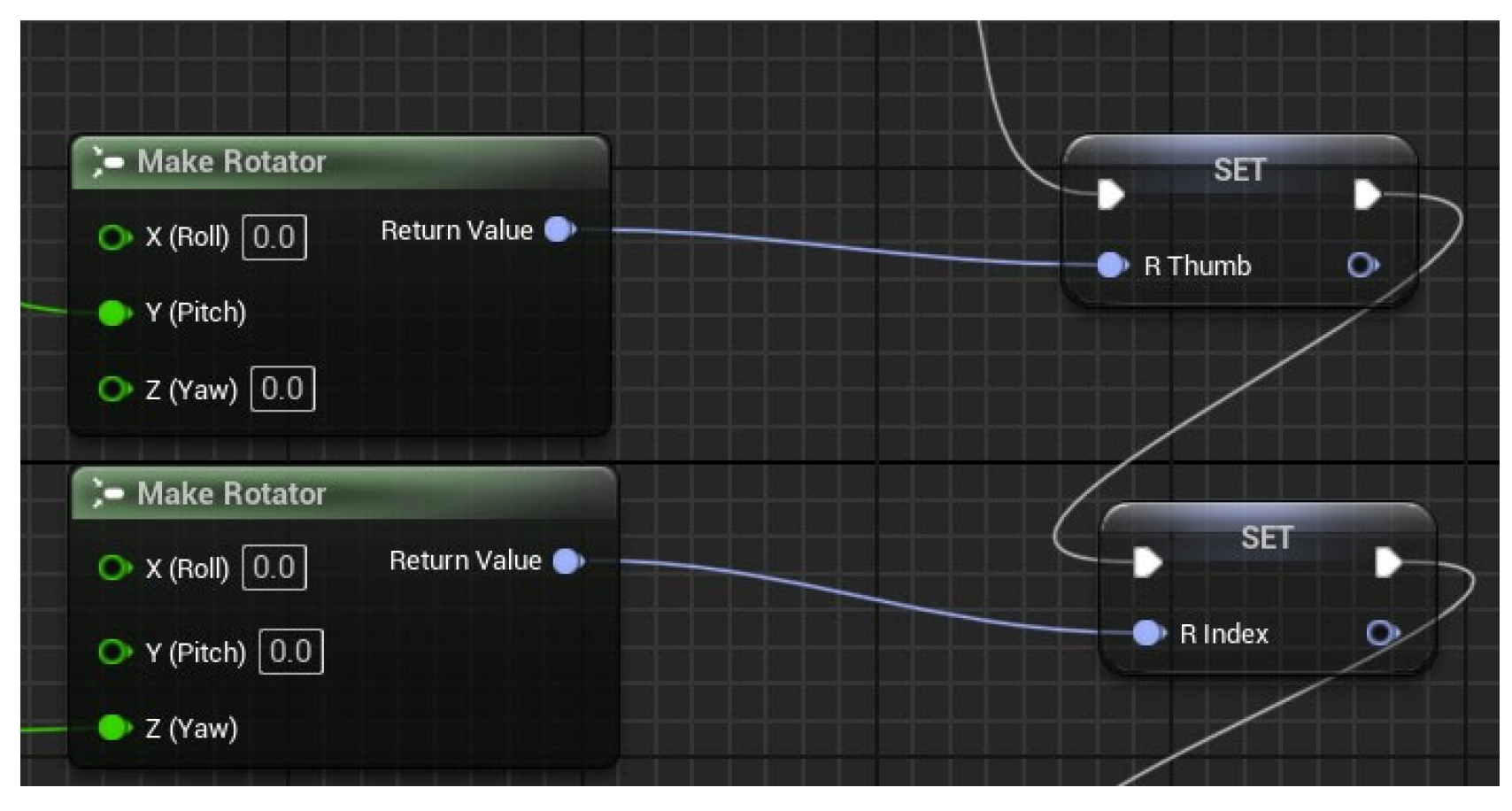
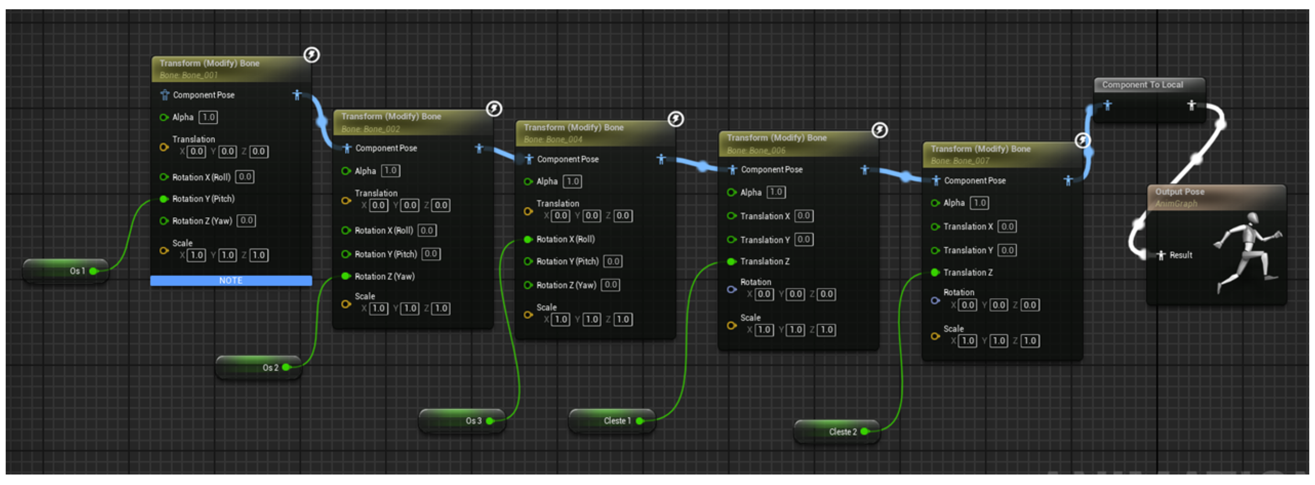
The objective of these calculations and models is to verify the system’s functioning and ensure compliance with the technical-functional requirements dictated by the design theme. This method is streamlined in Unreal Engine and condensed into a feature termed “Make Rotator,” illustrated in
Figure 7.
The finger movement commences at an entirely open position, regarded as the reference position at the beginning time t0. During operation, the system processes data from the resistive rotating sensors, which are appropriately positioned on each finger, in real time. The acquired analog values are utilized in the aforementioned equations to ascertain the closing angles of each finger’s joints. Consequently, the location of each digital segment is perpetually revised in accordance with these values, guaranteeing a seamless and synchronized motion of the entire prosthetic hand.
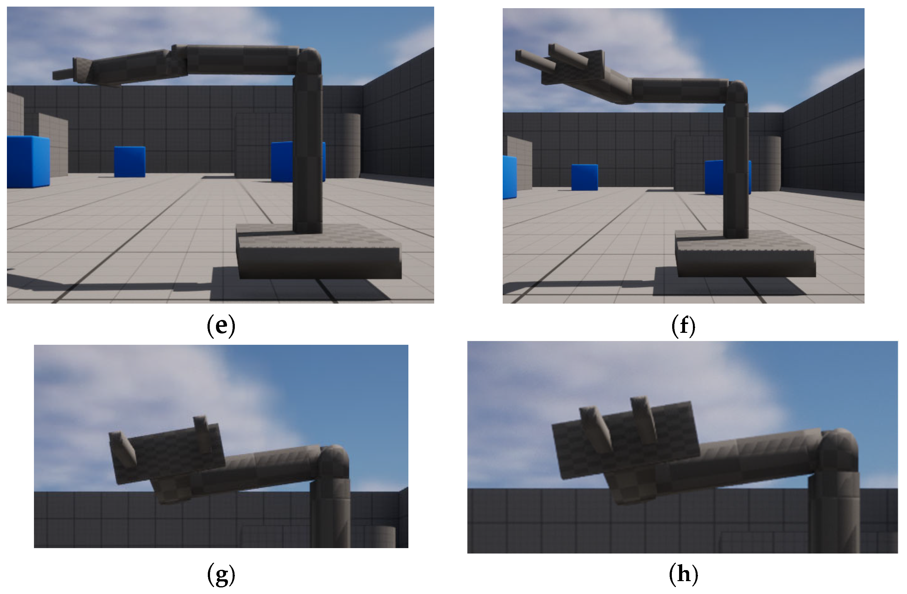
The initial image from
Figure 8 depicts the system’s condition at time t
0, when all fingers are positioned in the open state. The right image of
Figure 8 illustrates the hand’s final configuration at time t, with the fingers fully closed, resulting from the processing of inputs from resistive rotating sensors and the application of kinematic equations for each joint.
2.3. Mechanical Structure Design of the Controlling Device
The mechanical architecture of the VR glove system is a critical element of the entire design, directly affecting motion tracking precision, user comfort, and long-term durability. The selection and incorporation of mechanical and electronic components prioritized modularity, ergonomics, and lightweight design to facilitate a seamless experience in virtual reality. The glove comprises five modules, each corresponding to a finger, all incorporated into a central unit located on the rear of the palm. Each module includes a linear resistive rotary sensor physically affixed to monitor the flexion and extension of the corresponding finger. The motion of each finger is regulated by an SG90 servo motor, operated by a tensioned wire mechanism, enabling the fingers to open and close in response to signals from the control system.
The support for these components possesses a specified geometry to accommodate them. To fully incorporate the servo motor, adherence to the specifications defined is essential. The dimensions designated as B and D are crucial for ensuring proper and secure installation. Likewise, the dimensions of the resistive rotating sensor are illustrated in
Figure 9. The measurements to be considered for the proper installation of the resistive rotating sensor are the diameter of its body and the length of the component to which the connecting pins are affixed. These dimensions are crucial for guaranteeing mechanical stability and facilitating access to electrical connections.
A crucial element in the proper assembly of the subassembly on the VR glove is the sliding mechanism, which ensures the secure movement and fixation of the components. This mechanism guarantees a consistent, rapid, and precise installation of the modules onto the bracket affixed to the hand. The dimensions of the sliding mechanism are essential for the system’s proper operation. The dimensions of 18.55 mm (width of the guiding element) and 1.55 mm (height) must be securely fixed to ensure the aforementioned parameters.
The sliding mechanism serves as a mechanical guide, facilitating the insertion and secure fixation of the module in a precise location, thereby preventing positioning errors that could compromise both the physical movement of the fingers and the data interpretation from the sensors. This technique is optimal for wearable devices, where spatial constraints exist and installation durability is crucial for safety and comfort.
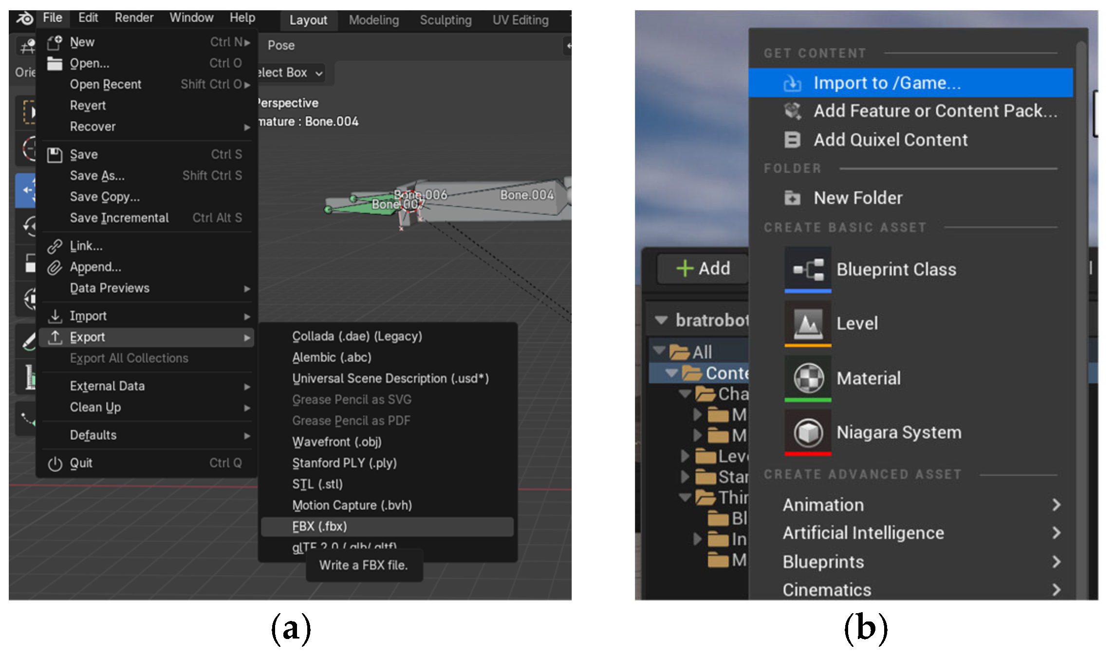
The control and command system of the suggested VR glove is constructed on a distributed architecture, whereby proper functionality relies on the interaction of two microcontrollers: ESP32 and ESP8266. The ESP32 module, connected to the user’s glove, primarily functions to gather data from the sensors and regulate the drives. The ESP8266 module is linked to a computer and facilitates connection with the virtual world developed in Unreal Engine 5.
The collection of finger position data is executed by five spinning resistive sensors, arranged to accurately represent the movement of each finger. The analog readings acquired by the ESP32 microcontroller are analyzed and correlated with the actual bending angles of the joints. The hand’s spatial orientation is concurrently ascertained using an MPU6050 inertial sensor, which combines an accelerometer and a triaxial gyroscope. This orientation is crucial for accurately depicting the hand’s position in virtual space.
After local data processing, the ESP32 microcontroller relays the information to the ESP8266 module through a WiFi connection, employing a UDP communication protocol. The ESP8266 acquires this data and relays it to the PC using the USB serial port. The program created in Unreal Engine 5 processes this data in real time and produces an accurate representation of the user’s hand movements within the virtual environment.
The system is bidirectional, facilitating the transfer of actual motions within the virtual environment and the return of commands from the computer to the physical glove. The computer transmits positioning orders for the five finger-mounted servo motors via ESP8266 and subsequently through ESP32. The PWM signals, generated by the ESP32, regulate them according to data received from the VR application.
The data flow between components is constant and coordinated, ensuring minimal latency and a seamless user experience. The system’s control and command rely on a cohesive integration of hardware components (sensors, microcontrollers, actuators) and the software environment, enabling the translation of real movements into an interactive virtual environment.
The system’s fundamental element is the ESP32-WROOM-32D microcontroller (Espressif Systems, Shanghai, China), a multifunctional and high-performance module including a dual-core Xtensa LX6 CPU (Espressif Systems, Shanghai, China) operating at a frequency of up to 240 MHz. The platform provides a substantial quantity of input/output (I/O) pins, with 38 accessible on the version utilized in this project. The ESP32 features comprehensive support for digital communications (I2C, SPI, UART) and incorporates a 12-bit resolution analog-to-digital converter (ADC) [
24].
The ESP32 within the system gathers and interprets sensor data while simultaneously controlling the servo motors’ positions in real time, according to incoming commands or locally generated data. This module can connect efficiently with other microcontrollers or mobile devices due to its native WiFi capability and strong processing capacity, eliminating the need for extra network components.
The NodeMCU ESP8266 module serves as an interface between the ESP32 and the computer executing the program created in Unreal Engine 5. In contrast to the ESP32, the ESP8266 is a more basic, single-core microcontroller operating at 80 MHz (or 160 MHz in turbo mode); however, it provides reliable WiFi connectivity and an adequate number of I/O pins for bidirectional data transmission to and from the PC via the USB serial port. The available number of pins is quite limited, around 11 functional digital pins, although this is adequate for the intermediary role it fulfills within the system.
The integration of ESP32 with ESP8266 modules constitutes a cost-effective, low-complexity, and performance-efficient solution.
The electronics utilize the ESP32-WROOM module, incorporating a sophisticated data acquisition and driving system that integrates five resistive rotary sensors, five SG90 servo motors, and an MPU6050 module.
The connections were established to facilitate concurrent and hardware-independent operation among the modules linked to the microcontroller, utilizing the designated pins for each function: analog (ADC), PWM signal, and I2C communication.
Resistive rotating sensors function as position sensors to detect finger movement, generating analog signals that are proportional to the rotation of their spindle. The signals are linked to the analog inputs of the ESP32, especially to the GPIO32, GPIO33, GPIO34, GPIO35, and GPIO39 pins. The selection of these pins is due to their association with the ADC1 block, which is favored for analog signal acquisition as it maintains functionality and stability throughout WiFi activities.
GPIO34, GPIO35, and GPIO39 are pins designated just for input, rendering them optimal for capturing analog signals from resistive rotating sensors, as no digital output is required. Connecting the resistive rotating sensors requires providing them with 3.3 V, linking the common ground (GND) to the system’s reference, and connecting the center pin to the specified analog inputs.
The control of the five SG90 servo motors utilized pins GPIO21, GPIO5, GPIO17, GPIO4, and GPIO27. These ports may provide PWM signals, essential for regulating the position of the servo motors. The ESP32 facilitates the generation of precise PWM signals over numerous pins, selected to avoid interference with the board’s essential boot or communication operations. The control signal for each servo motor is transmitted to the respective pin of the ESP32.
The MPU6050 module, comprising an accelerometer and a 6-axis gyroscope, utilized the I2C protocol, implemented on the ESP32′s GPIO18 (SDA) and GPIO19 (SCL) pins. The microcontroller’s conventional I2C pins are typically supported by most libraries utilized for the MPU6050. The module operates at 3.3 V, with a shared ground with the circuit, assuring logical compatibility and optimal functionality of the I2C bus.
Consequently, the allocation of the pins in this configuration was executed by taking into account the functionalities of each pin on the ESP32 and the particular specifications of the linked components. The objective was to utilize the ADC1 block solely for acquiring data from resistive rotating sensors, to designate PWM pins that do not play a crucial part in the boot process for servo control, and to adhere to conventional I2C protocols for communication with the MPU6050. This produces a cohesive, resilient architecture that aligns with the demands of interactive or robotic applications utilizing this arrangement.
This setting ensures the components’ power supply is intended for dependable operation and prevents overloading the internal regulator of the ESP32 board. The three primary component groups (ESP32, resistive rotary sensors, and servo motors) had distinct power supply requirements yet are interconnected via a shared ground point (GND), essential for the system’s optimal functionality.
The ESP32-WROOM board receives power through its input connector (by USB) and, when mounted on the breadboard, directly provides the 3.3 V necessary to power the resistive rotating sensors and the MPU6050 module. The voltage is sourced from the 3.3 V pin of the ESP32 board, which is linked to the positive rail of the upper section of the breadboard. The resistive rotating sensors function in passive mode and use minimal current, allowing the ESP32 to directly supply the five sensors without concerns of heat or voltage drop issues.
SG90 servo motors exhibit significantly higher power consumption, particularly under load, with each motor potentially requiring currents of 250–500 mA or greater in lock-up mode. Consequently, their power supply is derived not from the 5 V pin of the ESP32 board, but rather from an external 5 V source.
It is important to acknowledge that all metrics (GND) are interconnected. The common ground point is crucial for the control signals (PWM) transmitted by the ESP32 to the servo motors, as it provides a shared reference; without it, the motors would fail to correctly identify the positioning pulses. The absence of a uniform mass may result in inaccurate or entirely dysfunctional engine actions.
2.4. System Programming
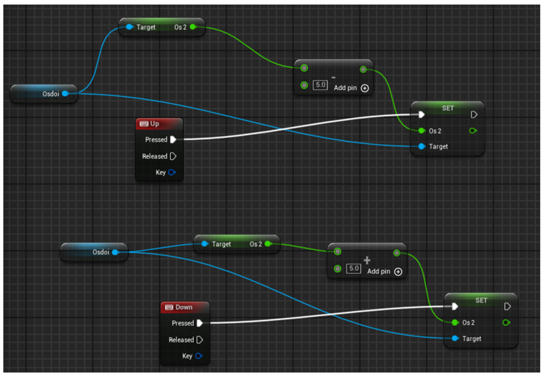
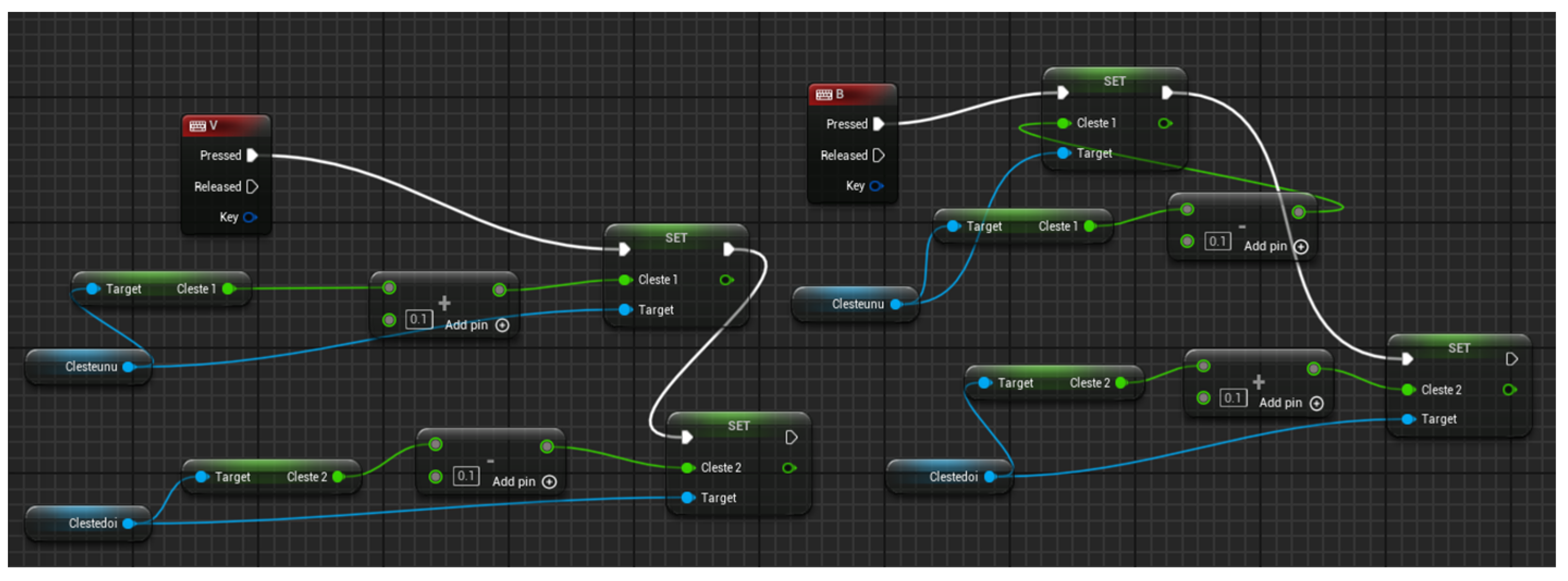
The system consists of three applications operating concurrently to replicate movements in virtual space while also receiving commands from it. The ESP32 and ESP8266 microcontrollers are programmed via Arduino and the C++ (Visual Studio 2022) programming language. The software operating on the computer is developed in Unreal Engine 5, utilizing a method particular to this platform, specifically Blueprint. In Unreal Engine, Blueprints constitute a visual programming framework enabling developers to formulate game logic without the necessity of coding in C++. This technology is integral to the Unreal Engine architecture and has been developed to offer a straightforward and cost-effective solution for both developers lacking programming expertise and those seeking to rapidly construct working prototypes. Blueprints have a node-based graphical interface, wherein each node signifies a function, event, variable, or logical action. Nodes are interconnected by “wires” (connections), which delineate the execution flow and the relationships among data. This system enables the modeling of player behavior, the creation of graphical user interfaces (UI), collision management, object animation, game logic definition, and additional functionalities.
The program developed for the ESP32 is responsible for initializing the pins connected to physical components, including resistive rotary sensors, servo motors, and the MPU6050 motion sensor. It configures the PWM channels required for controlling the five servo motors, each corresponding to a finger of the glove, and creates an I2C connection with the orientation sensor.
Throughout execution, the microcontroller persistently acquires the analog values from the resistive rotary sensors, which indicate the precise positions of the fingers. The values are transformed into a range that corresponds to the PWM control signals, enabling the servo motors to follow the movement of the fingers.
Data from the accelerometer and gyroscope are concurrently analyzed to determine hand orientation, employing a complementary filter for enhanced stability and precision.
All this information is conveyed using the UDP protocol to an ESP8266 module linked to a computer. The application also enables the reception of control commands.
The data communicated from ESP32 to ESP8266 is formatted as [a; b; c; d; e; f; g; h; i; j; k], where a, b, c, d, and e represent readings from resistive rotating sensors; e, f, and g denote values for inclination, roll, and gyration; and i, j, and k indicate the positional data of the hand. The data obtained from Unreal Engine via the ESP8266 module is formatted as [a; b; c; d; e], with each value representing a finger of the hand. The readings may reach 100 when the user fully flexes the finger and drop to 0 when the finger is completely extended. In standard operation, the servo motors monitor the position of the fingers based on the readings from the resistive rotary sensors. When the system identifies that a virtual object is gripped (value 100), the movement of the servo motors is suitably constrained, inhibiting further finger movement and thereby imitating tactile resistance. Consequently, the application establishes a comprehensive interface between the individual donning the glove and the digital or robotic environment, enabling seamless and instantaneous interaction.
The ESP8266 application aims to provide bidirectional communication between the ESP32 and the Unreal Engine virtual environment via the WiFi network and the UDP protocol. Initially, the WiFi connection is formed with the local network’s name and password. Subsequently, two UDP channels are established: one for receiving data from the ESP32 and another for transmitting data back to it, contingent upon orders received from Unreal Engine via the serial port. The module receives messages transmitted over UDP from the ESP32 in the main loop and forwards them to Unreal through the serial interface. Concurrently, it acquires serial data from Unreal (in textual format) and transmits it to the ESP32 over UDP, thereby facilitating the synchronization of physical and virtual activities.
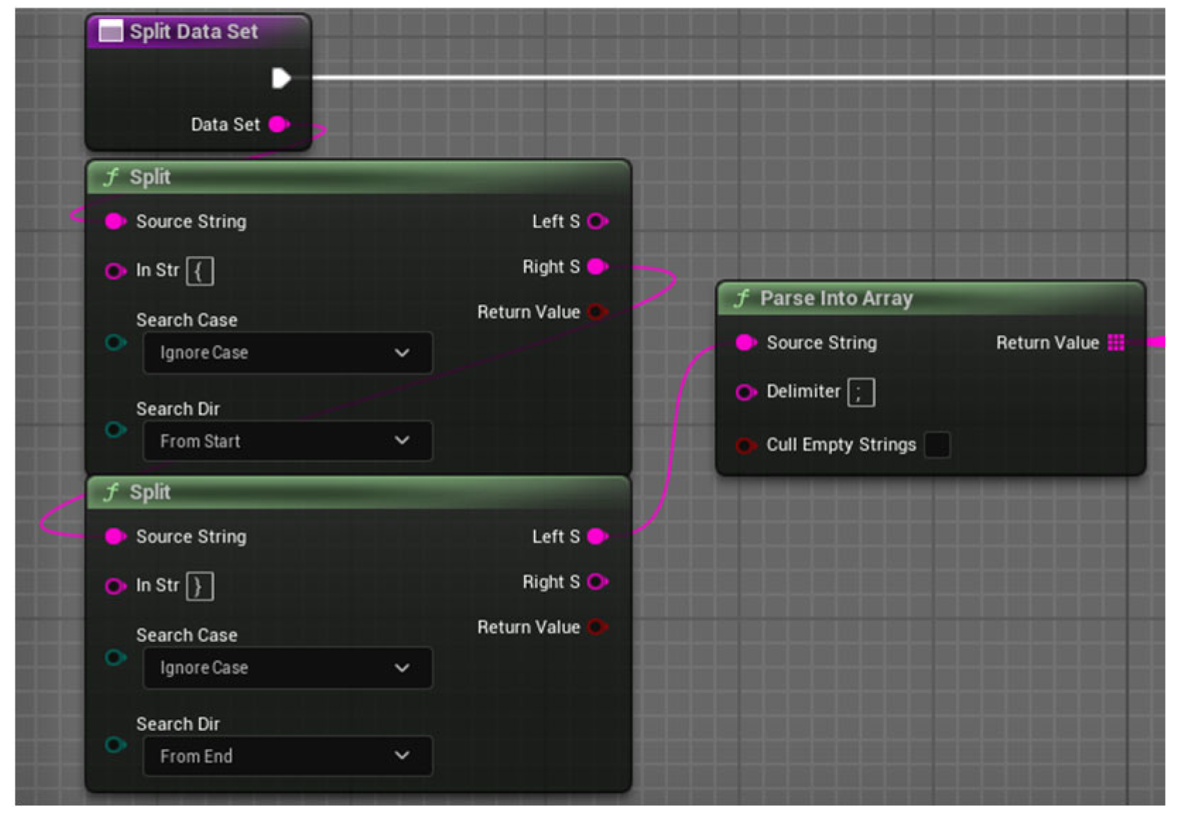
The Unreal Engine software is more intricate; nonetheless, we will concentrate solely on some key components. The initial aspect is communicating with the ESP over the serial port. The Serial COM plugin for Unreal Engine 5 facilitates bidirectional communication between the graphics engine and an external device via the serial port. It enables the establishment of a serial connection, the transmission and reception of data in text or binary format, and its incorporation into the application logic through the use of Blueprints nodes. Consequently, data from sensors or external orders may be utilized to manipulate virtual objects, while Unreal can transmit responses to the physical device. Select the port and communication frequency (115,200 for ESP32), then initiate the communication. Upon receipt of data over the serial port, it is parsed—
Figure 10, transforming the raw string of characters into a structured format that is readily interpretable and used within the application.
After receiving the string, the system checks that it complies with the default format of type {a; b; c; d; e; f; g; h; i; j; k}. If this condition is met, the string is divided into an array of individual components, using the “;” symbol as a delimiter. Subsequently, each element in the array is accessed by its position and converted from textual format (string) to numeric format (float) so that it can be used in calculations, controlling movements or updating states in the virtual environment. This process ensures a correct and precise interpretation of the transmitted data. For the position of the fingers, the values from 0 to 4 are used, which represent the data from the resistive rotating sensors; it is checked that they belong to the range of values for the movement of the fingers, and the position in the virtual environment is set—
Figure 11.
The hand’s orientation is ascertained by employing a comparable procedure that involves extracting data from the MPU 6050, located at array positions 5, 6, and 7. The values are modified by multiplying by −1 when necessary to accurately align the physical orientation of the hand with its representation in the virtual world (
Figure 12), and thereafter assigned to the relevant parameters of the virtual model.
The virtual environment has two primary entities known as actors. The primary actor is the hand. The secondary principal actor is the thing that can be manipulated with the glove.
In the virtual world established in Unreal Engine, the virtual hand is depicted by an actor consisting of multiple interrelated components, each designated for particular functions in its rendering and control.
The fixed configuration of the hand, designated as “VR_Hand_Right”, signifies the static 3D model employed for the overarching display of the hand in virtual environments. The corresponding blueprint, designated “VR_Hand_Right_BP”, encompasses the functional and behavioral logic of the hand, facilitating interactions and responses to external orders. The physics element, ‘VR_Hand_Right_Physics’, delineates the object’s physical attributes, including collision dynamics and force responses, and is crucial for authentic modeling of interactions with other objects. The hand’s skeleton, referred to as “VR_Hand_Right_Skeleton,” supplies the requisite virtual bone framework for animation, while the “VR_Hand_Right_Skeleton_Animation” file encompasses the animations linked to this skeleton, facilitating the replication of natural finger and hand movements.
These components collaborate to establish a cohesive and engaging framework for depicting the hand in virtual reality. By utilizing the program’s components, we can identify collisions between the hand and the object within the virtual world and communicate orders to the servo motors to prevent the fingers from closing when the object is grasped.
4. Conclusions
In this paper, we present human–machine interaction system utilizing a smart glove, proficient in detecting hand gestures and replicating them in real time within a virtual world and controlling a robotic arm that can manage thermally processed objects from laser treatment stations, through cryogenic treatment, and ultimately to the testing stand. The primary objective of this paper is to propose and present the concept and key features of the mechatronic platform, with the aim of implementing the physical experimental model.
The mechatronic platform consists of laser equipment, cryogenic equipment, two robotic positioning systems, the controlling unit, and an optical measurement stand. In this article, we exclusively concentrate on robotic positioning systems, specifically robotic arms and grippers, and we showcase two distinct types of these systems. We use 3D printing to manufacture the parts of robotic arms and grippers. The article presented an example of the parameters and key steps required to manufacture the base of the first robotic arm.
The proposed controlling device incorporates position sensors (resistive rotating sensors) affixed to each finger, an MPU6050 inertial module for ascertaining the overall orientation of the hand, and a series of SG90 servo motors to replicate the sensation of grasping. The system is orchestrated by two microcontrollers: an ESP32 on the mobile side (glove) and a stationary ESP8266, which interacts over the UDP protocol, facilitating an efficient bidirectional connection between the actual and virtual realms.
The system described is complex, requiring extensive examination and construction. We must optimize, build, and test positioning systems experimentally in the future. Furthermore, we must optimize the trajectory’s components in terms of hardware resource usage and user-friendliness and develop a user interface. Additionally, the measuring stand must integrate the software required to assess the quality of the laser.
The development prioritized critical elements of mechatronic design, including downsizing, energy efficiency, communication reliability, and system adaptability. The personalized calibration of the resistive rotating sensors enabled the glove to fit to various anatomical structures of the human hand, enhancing precision in ascertaining finger positioning.
The integration of the MPU6050 enhanced the simulation’s realism, enabling the system to replicate the hand’s three-dimensional orientation in space. Communication across ESPs was established with little latency, and real-time control of the servo motors exhibited a high degree of realism in response to actual user motions, which constitutes an advantage over other similar systems. The main constraint of the remote control is the low speed and repeatability, which are highly dependent on the user experience.
A notably significant facet of the project is the integration of the physical system with the virtual environment created in Unreal Engine. This integration enabled the visualization of movements in virtual space and the transmission of orders to the physical system, facilitating a bidirectional feedback interface—an essential component in advanced virtual reality, robotics, and medical rehabilitation applications.
The experimental findings validate the system’s proper operation, its capacity for real-time responses to multiple inputs, and its adaptability across many circumstances. The advanced smart glove serves as a working prototype for several research avenues or commercial applications, including VR simulations for professional training, video games, or myoelectrically controlled prosthetics.
In conclusion, the suggested idea enhances the notion of a natural interface between humans and cyber systems, marking a significant advancement in the development of portable, interactive, and precise technologies. The selected hardware–software architecture provides both performance and scalability, allowing for straightforward expansion with additional modules or functionalities, such as haptic feedback, intricate gesture detection, or machine learning for behavioral customization. The integrated approach illustrates both the feasibility of a functional technical solution and its capacity for conversion into a tangible product.
Notwithstanding the strong functionality and promising outcomes attained in the project, there exist several avenues for enhancement and expansion that can be pursued in the future, with the objective of augmenting the system’s performance, portability, and applicability in real-world and intricate situations.
A crucial developmental focus is the accurate identification of the hand’s position in three-dimensional space, beyond merely assessing the orientation and relative placement of the fingers. To do this, supplementary technologies such as stereo cameras, infrared (IR) sensor stations, or AprilTag-based motion detection systems may be incorporated, strategically placed within the environment to monitor the hand’s absolute position relative to a global reference system. This form of localization would facilitate more accurate interactions in augmented or virtual reality settings, as well as sophisticated manipulation applications, where precise positioning is crucial.
A crucial focus is the downsizing and enhanced integration of electrical and mechanical components. The system presently employs modular components (ESP32 board, MPU6050, SG90 servo motors, etc.), which, while efficient for development, take considerable space and may affect user comfort. The next phase of research will entail the design of bespoke circuit boards, tailored for compactness and efficiency, alongside the integration of miniature actuators utilizing linear servo mechanisms, shape-memory polymers, or diminutive pneumatic actuators. This integration procedure will result in the development of a portable, lightweight, ergonomic, and durable gadget, crucial for professional or commercial applications.
Alongside the hardware components, the software aspect could also undergo substantial enhancements. The deployment of sophisticated filters to enhance the precision of sensory input, together with the incorporation of machine learning algorithms for gesture identification and categorization, would facilitate novel avenues for natural interaction between the user and the system. A potential avenue for expansion is to enhance the communication protocol and minimize latency by transitioning from UDP to hybrid or specialized protocols for real-time applications (e.g., MQTT or ROS 2), contingent upon the application’s complexity and bandwidth constraints.
Another significant study is the investigation of the parameters and processes of thermal processing through an applicative study of the materials and surfaces to be processed.
