1. Introduction
The transport industry is a strategic component of the European economy, which includes rail, road, water (sea and river), and air transport modes, as well as pipelines. However, the most popular among them is railways, which accounts for a significant segment of passenger and freight traffic [
1,
2].
The higher efficiency of the transport industry is mainly due to the combined transportation and interaction of different transport modes [
3,
4,
5]. The most popular type of combined transportation is container transportation, which can be explained by the fact that containers can be transported by all transport modes. Thus, this eliminates the need to transship cargoes from one mode of transport to another and speeds up the process of delivering goods from consignor to consignee [
6,
7].
Transportation of liquid bulk cargo is quite hazardous, due to the additional dynamic impact from the bulk cargo on the tank container. The dynamic loads acting on the tank container contribute to the additional load on its structure, which affects not only its strength and stability, but also the safety of transportation and environmental friendliness. This is especially true for rail transport, because the largest dynamic loads act on the tank container during rail transportation [
8]. Therefore, it is important to find solutions that will reduce the dynamic load of the tank container transported by rail.
Currently, significant attention is paid to designing means of transport with improved technical performance. For example, study [
9] describes potential ways to improve tank containers and gives their structural and functional analysis. Based on this analysis, ways to design tank containers with improved operating characteristics are being developed. However, the author does not give any examples of the implementation of these improvements.
The research team of study [
10] performed a strength analysis of the structure of the 1AA tank container for transporting liquefied natural gas. The influence of inertial forces on the strength of the tank container during its transportation is considered. The results of the analysis make it possible to identify the patterns of loading the tank container components under inertial forces.
The longitudinal load of the tank container is investigated in study [
11]. The effect of a collision on the strength indicators of the tank container is considered. Particular attention is paid to determining the stresses in the tank container frame. The theoretical results of the strength assessment are confirmed by experimental studies. It is proved that the accelerations acting on the tank container during a collision exceed the standard values. The disadvantage of the studies covered in [
10,
11] is that the authors do not propose any solution for a reduction in the dynamic load caused by the tank container due to inertial forces acting on its structure.
A comprehensive analysis of the strength of tank containers with various frame designs is presented in [
12]. The authors investigate the transportation of tank containers on a gas tanker. The strength is assessed using the requirements from the ASME international standard. The results of the analysis make it possible to identify both the positive aspects and shortcomings of each of the proposed options for the structural design of the tank container frame. The study also provides recommendations for tank container designs. However, the authors do not investigate the possibility of using energy-absorbing components to reduce the tank container load.
The strength of the food tank container is described in [
13]. The authors propose a design model of the tank container, which can be used to determine its main strength indicators. The model is validated by comparing the achieved results with the experimental data provided by the manufacturer. A solution for its improvement is proposed to reduce the most loaded areas of the tank container. The results of the calculations demonstrate that this solution is effective. However, if the stresses in the tank container structure are reduced through strengthening the tank container components, the tare weight of the tank container will be increased.
The authors of study [
14] propose an additional element, namely a fork, to reduce the stresses in the area of interaction of the frame support with the bottom fittings of the tank container. Its end parts have braces that partially unload these assemblies. The authors calculate the strength of the tank container so as to substantiate the solution. It is found that such improvements will reduce stresses in the frame design in comparison with its typical design. However, no solution focused on improvement of the strength of the tank is proposed.
The fatigue strength of a new tank container design for liquefied natural gas under low- and multi-cycle loads is investigated in study [
15]. The calculation is implemented using the finite element method in the ANSYS simulation software (version 2023R1). The results of the calculation show that the tank container structure has a fatigue life of at least 20 years. However, no solution for increasing the service life of the tank container is proposed.
The strength of the tank container can also be improved by optimizing the frame [
16]. The criterion of reduction in the frame weight was applied for optimization of the tank container structure. The study resulted in the finding that the weight of the solved structure of the tank container frame is reduced by 18.4 to 37.3% in comparison with a prototype. These results are confirmed by the strength calculations of the tank container. However, the authors did not consider reducing the load of the tank container in operation.
Publication [
17] describes the design of a tank container for vegetable oils and describes the features of its testing. It highlights the procedure of experimental tests in the example of the shunting collision of a flat wagon loaded with tank containers. The achieved results show that the structural strength of the tank container is observed. However, no solution for improving the strength of the tank container design under operational loads is proposed.
Modular cargo complexes are proposed in study [
18] to increase the efficiency of liquid cargo transportation. These complexes are tank containers placed on flat wagons. They can transport cargoes from countries with a 1520 mm track gauge to countries with a 1435 mm track gauge. The author substantiates the use of such modular complexes and describes the prospects of their further development. However, no attention is paid to the issue of ensuring the durability of the modular complex components, particularly those used in tank containers.
The strength of the tank container can also be improved by introducing energy-absorbing elements into its design. Thus, a detachable module with energy-absorbing elements is proposed in work [
19]. These elements are placed in the fittings of the detachable module. Hence, under the inertial loads of its structure, the load of the detachable module is reduced. This solution is substantiated by theoretical calculations of the dynamics and strength of the detachable module design. However, this solution complicates the process of mounting the detachable module on other vehicles, for example, sea vessels, because it involves not only the lower openings of the fittings, but also the side ones.
The hypothesis of improving the strength of vehicles through the introduction of energy-absorbing materials into the structure is also confirmed in study [
20]. The authors propose the use of removable panels for wall paneling. However, the study is conducted only for a freight wagon, and the authors do not investigate the use of sandwich components with energy-absorbing material for a tank container.
Study [
21] describes a new approach of a tank container’s design, which is based on the interaction of the free surface of the liquid with the tank walls. This approach is substantiated both theoretically and experimentally. However, this method is not used in designing tank containers.
Similarly, study [
22] is focused on the strength analysis of the tank container structure. However, no solution for improving its strength in operation is given.
The issue of the structural optimization of vehicles is highlighted in works [
23,
24,
25]. For example, the improvement of the roof of the light-weight vehicle body is proposed in work [
23]. It was established that the proposed technical solution allows a reduction in the mass of the optimized unit by 63%.
The features of the choice of lightweight material for the creation of a railway vehicle are highlighted in work [
24]. The authors analyzed the possibility of using steel and aluminum materials. They listed the main disadvantages and advantages of using these materials.
The features of the optimization of a light-weight vehicle body made of composite materials are highlighted in work [
25]. The authors developed a multi-level procedure that allowed them to determine the optimal thickness of the body components. The conducted studies proved the feasibility of using this procedure. However, it should be noted that the number of advantages presented in works [
23,
24,
25] were not applied to tank containers.
The results of the structural analysis of a railway vehicle bogie frame are presented in study [
26]. Based on these results, it is possible to identify the types of deformations that most affect the bogie design. This necessitated a more thorough analysis of the individual types of loads acting on the bogie. A similar approach would be interesting to use for the construction of modular vehicles, particularly containers. However, the authors limited themselves to the study of bogies.
Works [
27,
28] highlight the design features of rail vehicles’ bogies. Structural topological optimization was used. The results of the study showed that the solutions proposed by the authors significantly reduce stresses in the bogie structural elements compared to their original designs. However, this design approach has not been used for tank containers.
The use of the dynamic optimization of dimensions method was proposed in study [
29] in order to improve the technical and economic parameters of vehicles. This method is aimed at reducing the mass of the vehicle’s metal structure by changing the thickness of individual components. The results of the optimization showed that the mass of the studied components decreased by 21% compared with the initial mass. It would be interesting to apply this method to the optimization of the parameters of tank containers. However, the authors did not conduct such a study.
A rather interesting design of panels for the manufacture of railway vehicles is proposed in work [
30]. This panel has a weight lighter by 35.5% than the standard one. The features of testing these panels under various types of loads are presented. It is established that the design of the panel satisfies the strength requirements. At the same time, the implementation of these panels is considered on an example of a medium-speed railway vehicle. An implementation of this method on the design of a tank container was not considered.
Work [
31] is also interesting. It highlights the features of the dynamic optimization of the geometric dimensions of the vehicle body components, which is made of aluminum and carbon fibers. The results of the conducted studies have established that there is a reduction in the weight of the analyzed structures compared to the initial one. This proved the prospects of applying the optimization process to railway vehicles, including tank containers. However, such studies have not been conducted by the authors so far.
An analysis of the properties of composite materials and the possibility of their application in vehicle structures is given in study [
32]. The study was conducted on a bus body. It was found that the use of composites contributes to a reduction in the body weight by almost 20% while ensuring the conditions of strength and operational reliability. However, the authors did not consider the possibility of using these materials in the manufacture of tank containers.
The issue of improving the technical characteristics of aerospace equipment using composite materials is highlighted in study [
33]. It is proven that the introduction of such materials into the design of rocket components contributes not only to a reduction in their mass, but also to an improvement in their strength characteristics. However, such an implementation was not considered by the authors in relation to the designs of railway vehicles.
The analysis of publications [
9,
10,
11,
12,
13,
14,
15,
16,
17,
18,
19,
20,
21,
22,
23,
24,
25,
26,
27,
28,
29,
30,
31,
32,
33] has shown that the development of modern structures of tank containers is an urgent issue requiring further research and that it should be aimed at increasing operational efficiency. Therefore, the main task of this presented research is to investigate scientifically the possibilities of substantiating an integration of sandwich components into the structure of a tank container. This purpose was achieved by undertaking the following tasks:
to research the longitudinal dynamic load of the tank container with sandwich components integrated into its main structure; and
to perform the strength analyses of the structure of the tank container with sandwich components in the structure and to conduct its modal analysis.
2. Materials and Methods
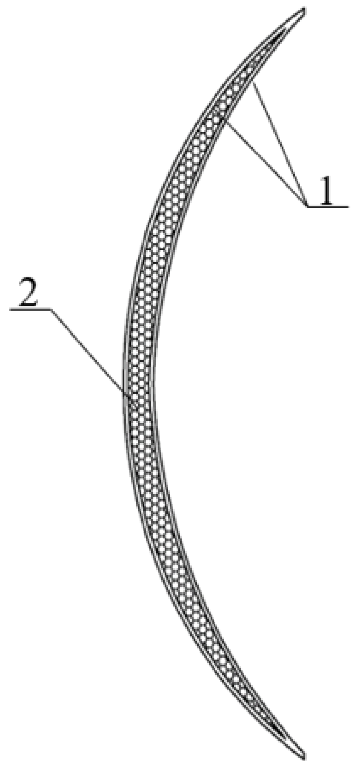
In order to reduce the dynamic load of the tank container during transportation, it was proposed to improve its tank design by using sandwich panels for the tank bottom (
Figure 1). A sandwich panel consists of two metal sheets with an energy-absorbing material placed between them.
This improvement of the tank container was substantiated by mathematical modeling. It was taken into account that the energy-absorbing material was a part of the sandwich panel and had different characteristics: elastic, viscous, and viscous-elastic. The TK-25 tank container was considered as a prototype.
The appropriate mathematical models were based on the assumption that the tank container was placed on the flat wagon (
Figure 2). The calculation scheme includes three bodies: a flat wagon, tank containers and bulk cargo loaded in them. The 13-4012 flat wagon was adopted as a prototype.
The shunting collision of the flat wagon was considered [
34]. This operating mode included the action of a force of 3.5 MN on the automatic coupler. The tank container was loaded up to the maximum load capacity. The bulk cargo (gasoline) in the tank was considered as a pendulum. By considering these assumptions, the derived calculation model considering the load acting on the tank container with rigid energy-absorbing material in its bottom was as follows:
where
Mw represents the total weight of the wagon considered (a flat wagon type);
Pl belongs to the force acting in the longitudinal direction to the automatic coupler;
FFR indicates the friction force, which appears between the fittings and the stops;
Mc represents the tank container weight;
Cf is the stiffness of the material in the bottom;
Mp is the weight of the pendulum that simulates the movement of the bulk cargo;
l is the length of the pendulum suspension;
Ip is the moment of inertia of the pendulum; and
q1,
q2,
q3 are the generalized coordinates that determine the movement of the elements of the design model (the flat wagon, the tank container, and the bulk cargo, respectively).
The numerical values of the input parameters for mathematical model (1) are given in
Table 1.
The derived calculation model is represented by a system of equations of motion (1), which is solved by the Runge–Kutta method. The algorithm of this method is implemented in the MathCAD software (version 2024) [
35,
36,
37,
38] using the algorithm from [
39,
40]. Initially, the model was reduced to the normal Cauchy form, and then it was integrated. Thus, it was reduced to the following form:
Here , , , ,
Generalized accelerations were calculated using arrays
ddqj,i:
The integration variable was time. The equations were solved in the interval of 5 s. The initial time of the process is denoted as
tn, and the final time as
tk. The calculation is performed for 5000 points. The integration step was determined based on the formula [
41]:
Thus, the integration step was 0.0001 s.
It was found that, in order to keep the acceleration of the tank container within the permissible values (4 g [
8]), the stiffness of the energy-absorbing material must be at least 418 kN/m. Thus, it was possible to reduce the acceleration of the tank container by 12% compared to that which was in the typical design.
When using a viscous material in a sandwich panel, mathematical model (1) was reduced to:
where
β represents the coefficient expressing the viscous resistance of the material used in the designed sandwich panel.
The input parameters of the mathematical model are identical to those used when solving model (1).
The solution to Equation (7) demonstrated that the coefficient of viscous resistance of the energy-absorbing material must be at least 10 kN∙s/m to keep the acceleration of the tank container within the permissible values. Considering the above facts, it was possible to reduce the acceleration of the tank container by 14.5% compared to that which was in the typical design.
For a viscoelastic material in the sandwich panel, mathematical model (1) was reduced to following form:
Thus, the acceleration of the tank container was lower by 18% than that which was acting in the typical design, with a stiffness of the energy-absorbing material of 450 kN/m and a coefficient of viscous resistance of 23 kN∙s/m.
The built models were verified by comparing the calculated results with those obtained by computer modeling. A finite element analysis was carried out in SolidWorks Simulation software (version 2024) [
42,
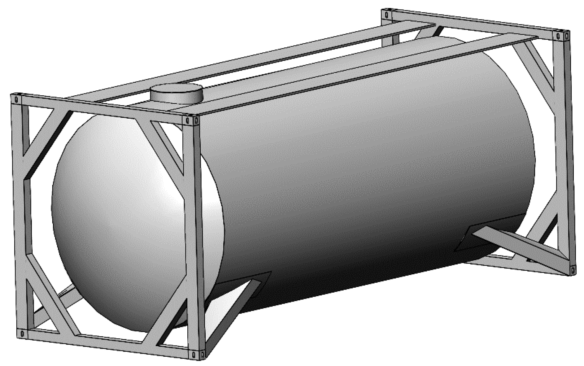
43]. The 3-D model of the tank container was built in SolidWorks (
Figure 3).
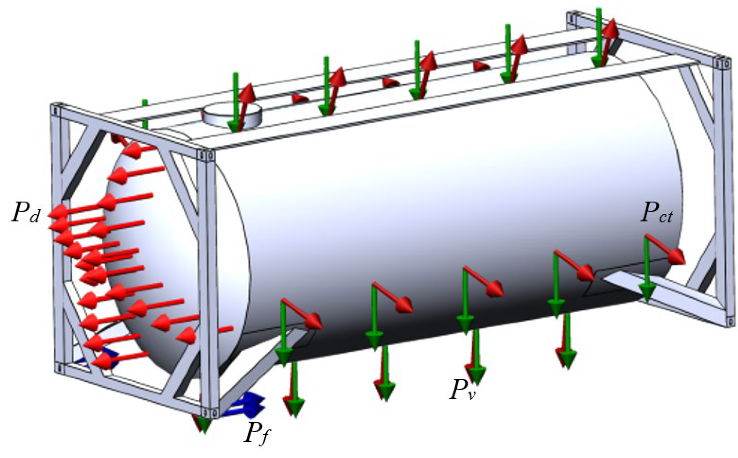
The following force factors are considered in the diagram of the designed tank container: the vertical force
Pv, the load pressure
Pp on the tank walls, the longitudinal force on the bottom
Pl, as well as the longitudinal forces on fittings
Pf (
Figure 4). The model was secured by the fittings of the tank container using a rigid connection [
44,
45]. It was considered that the material of the structure was Steel 09G2S with permissible stresses of 310.5 MPa [
34]. The main characteristics of this material are summarized in
Table 2.
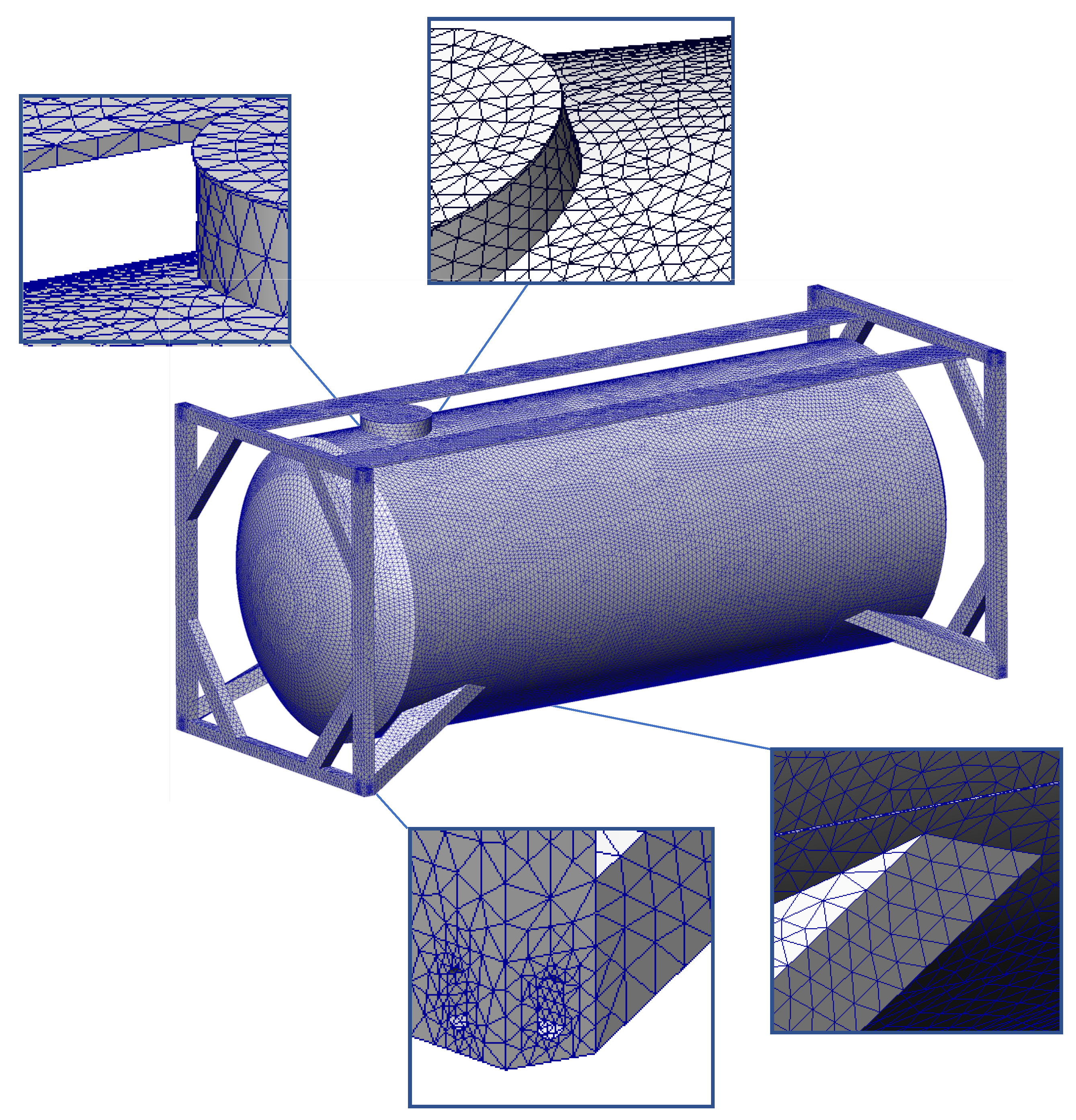
The finite element model (
Figure 5) was formed by the first-order elements—tetrahedral elements. The model included 118,926 elements and 232,230 nodes [
46,
47]. The maximum element size was 70 mm, and the minimum element size was 14 mm.
The finite element mesh was created based on curvature. The number of Jacobian points equaled 16. When constructing the mesh, its sensitivity was checked. At the initial stage, a visual inspection of the mesh quality was carried out. Built-in options of the software complex were used to assess the quality of the elements, which allows for identifying problem areas of the mesh. After that, the convergence of the mesh was checked. The results of calculations performed on meshes with different detail were compared for that. A special point was selected as a control (the zone of interaction of the cylindrical part of the manhole with the boiler), because changing the mesh can also cause a change in the nodes coordinates of the finite element model. Based on the performed calculations, the above-mentioned number of model elements was chosen.
It is important to note that the authors plan to conduct experimental studies in the future. Their results will allow for the re-checking of the finite element model and its possible modification.
The energy-absorbing material was simulated by the spring/damper connection, and it was taken from the database provided by the software package (
Figure 6).
This means that this connection was established in the layer formed by the bottom sheets.
3. Results and Discussion
The calculation was made for the viscoelastic material of the sandwich panel because it was the most efficient compared to other options considered according to the calculations.
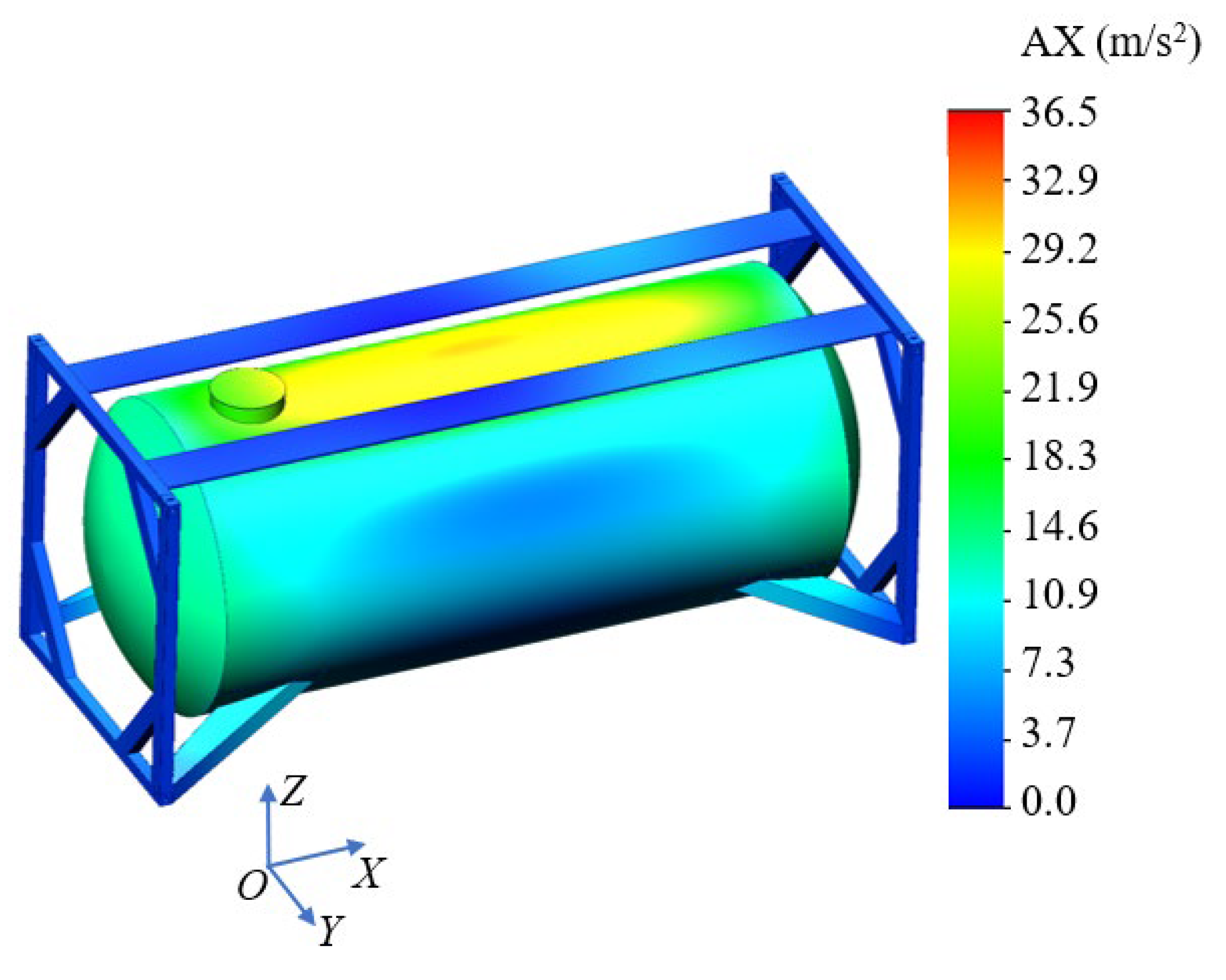
Based on the calculations, acceleration distribution fields in the tank container structure were obtained, and they are shown in
Figure 7. There are accelerations relative to the longitudinal axis, because the largest loads of the tank container appear in the longitudinal direction when transported by rail during operation. This is described in more detail in the normative document [
8].
The maximum acceleration acting on the tank was 36.5 m/s2. It occurred in the area behind the manhole. The acceleration acting on the bottom was about 23 m/s2.
The variation calculations of accelerations that occurred in the tank container during the shunting collision of the flat wagon were carried out using the derived mathematical model (8). The calculation was made for a situation in which the different longitudinal forces acted on the rear automatic coupler part of the flat wagon. The range of this force was considered within a range from 1.5 to 3.5 MN. The optimal number of tests was determined using Student’s
t-test [
48]:
where
t is the value determined by the Laplace function;
σ is the root mean square deviation; and
δ2 is the error that occurs during measurements.
The results of the calculations are presented in
Table 3. They are based on mathematical model (8) and the design diagram shown in
Figure 4.
It was found that the number of tests conducted was sufficient to obtain a reliable result, because their number was nine. It is more than six, as obtained by Formula (9).
The F-test, or Fisher’s criterion, was used to verify the models built [
49]. The value of the criterion was calculated, and then it was compared with the tabular value by comparing two dispersions—adequacy
and error mean square
:
The calculation was carried out within the confidence interval from −0.95 to +0.95. The coefficient of determination was 0.81. Its value was calculated with the sum of the squares of the residuals of 64.8 and the total sum of the squares of 348.12.
It was found that the calculated value of Fisher’s criterion was 1.18. This value did not exceed the tabular value of 3.29. Thus, it can be concluded that the hypothesis of the model’s adequacy was confirmed.
The design diagram shown in
Figure 4 was also used to determine the stresses in the improved tank container design. The calculation results can be seen in
Figure 8,
Figure 9,
Figure 10 and
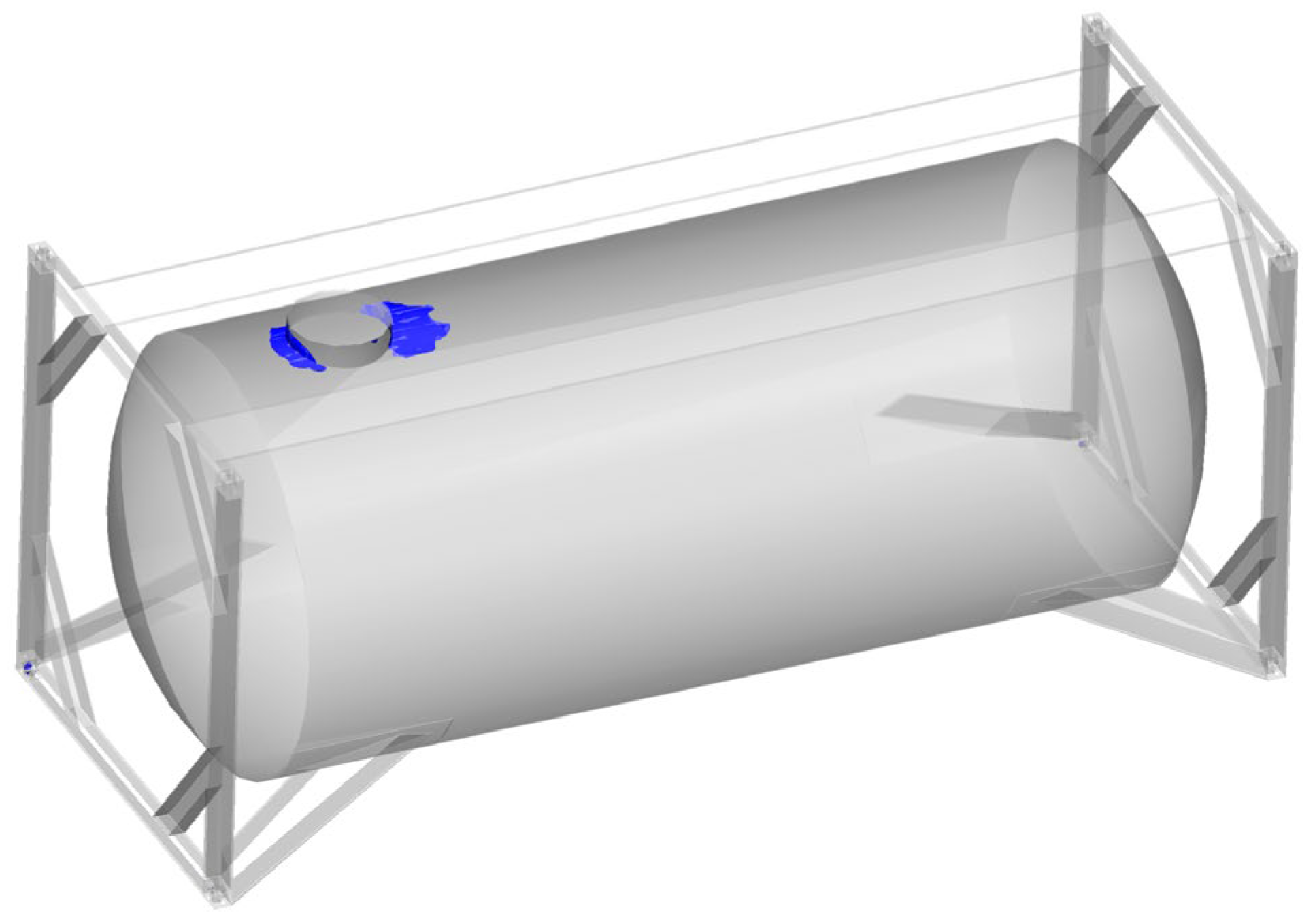
Figure 11. The maximum stresses were recorded in the manhole area (
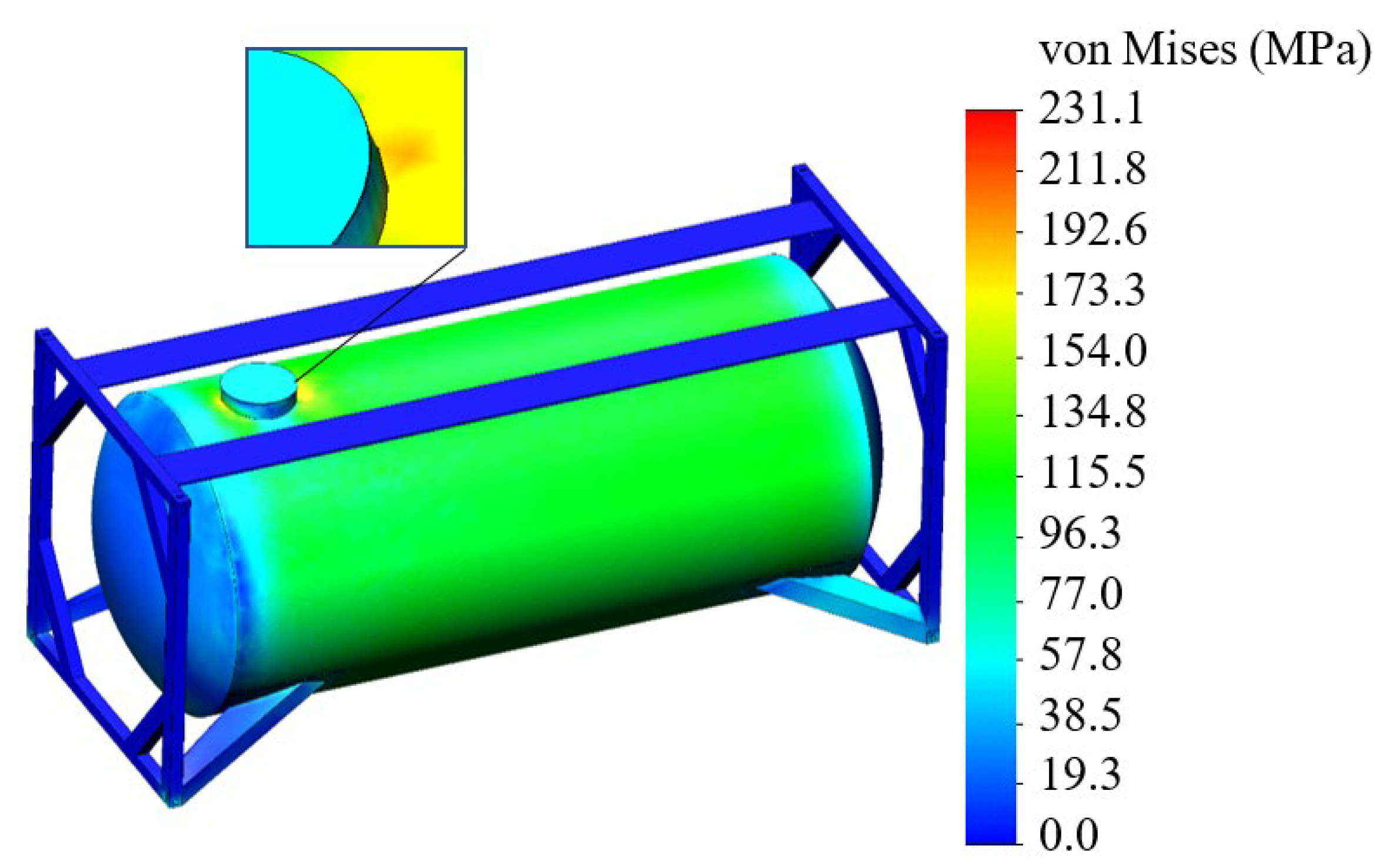
Figure 8). The most loaded area in the tank container is marked in blue. These calculated stresses are safely under the permissible value, 310.5 MPa, at which the maximal achieved value of stresses in the container structure is 231.1 MPa (
Figure 9).
Figure 9 shows that the stresses had maximum values on the side of the manhole, and then they decreased along the length of the cylindrical part of the tank. The resulting stresses were lower than permissible by 25.6% and lower by 24% than those in the typical tank container design.
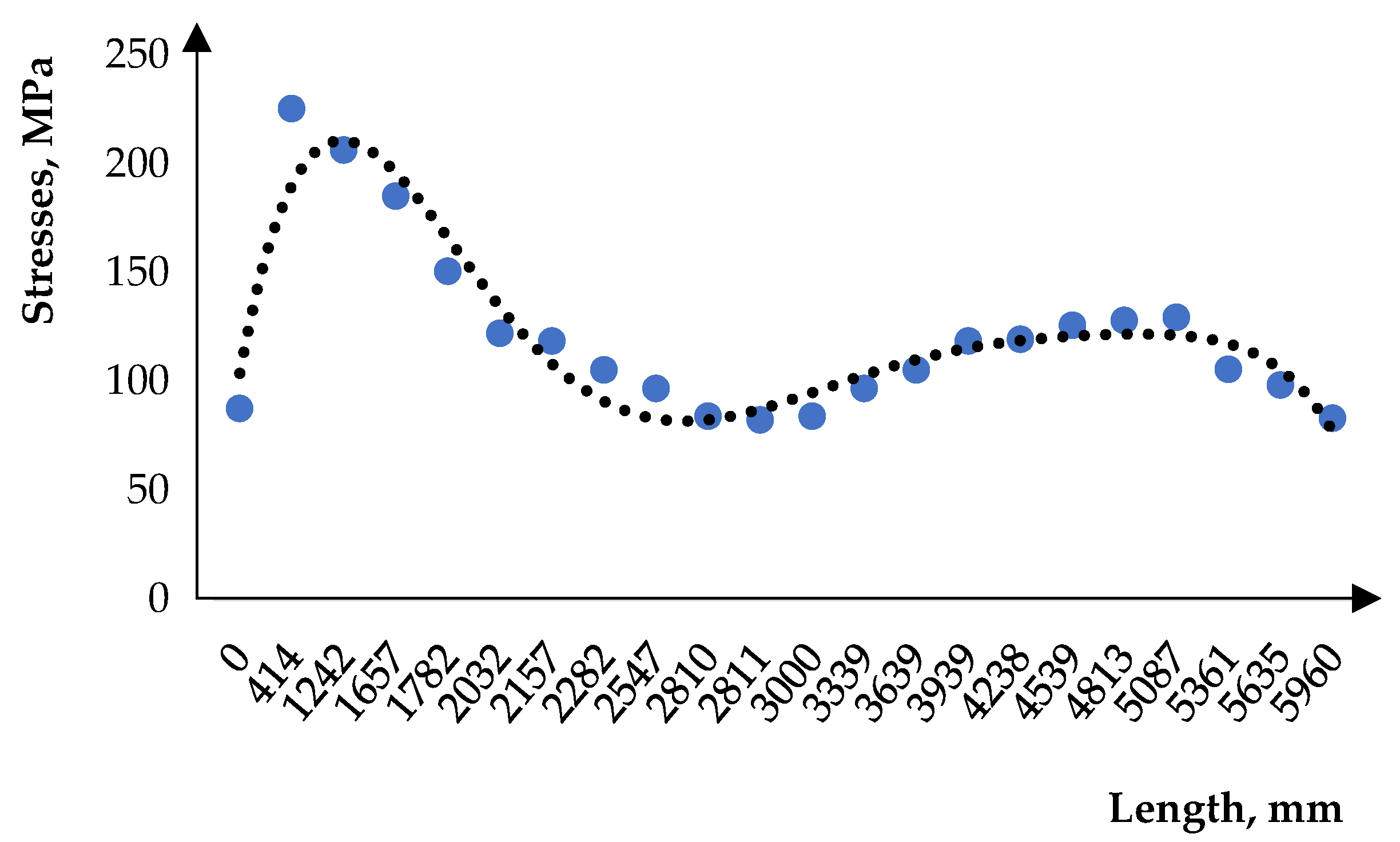
The distribution of stresses over the top of the tank cylindrical part can be seen in
Figure 8. This distribution is described by a function of the following form:
where
y is the value of the stress and
x is the length of the frame.
Equation (11) was obtained using the built-in options of the Excel software package (version 2024), in which this dependence was formed. The stress readings for creating the dependence shown in
Figure 10 were taken using the “probe” option of the calculation software package. These stresses were detected along the upper part of the boiler—from the manhole to the bottom part opposite to it.
This distribution of stresses can be explained by the fact that the manhole is a source of stress concentration, because it is located on the boiler cylindrical part on the side of the longitudinal loads action.
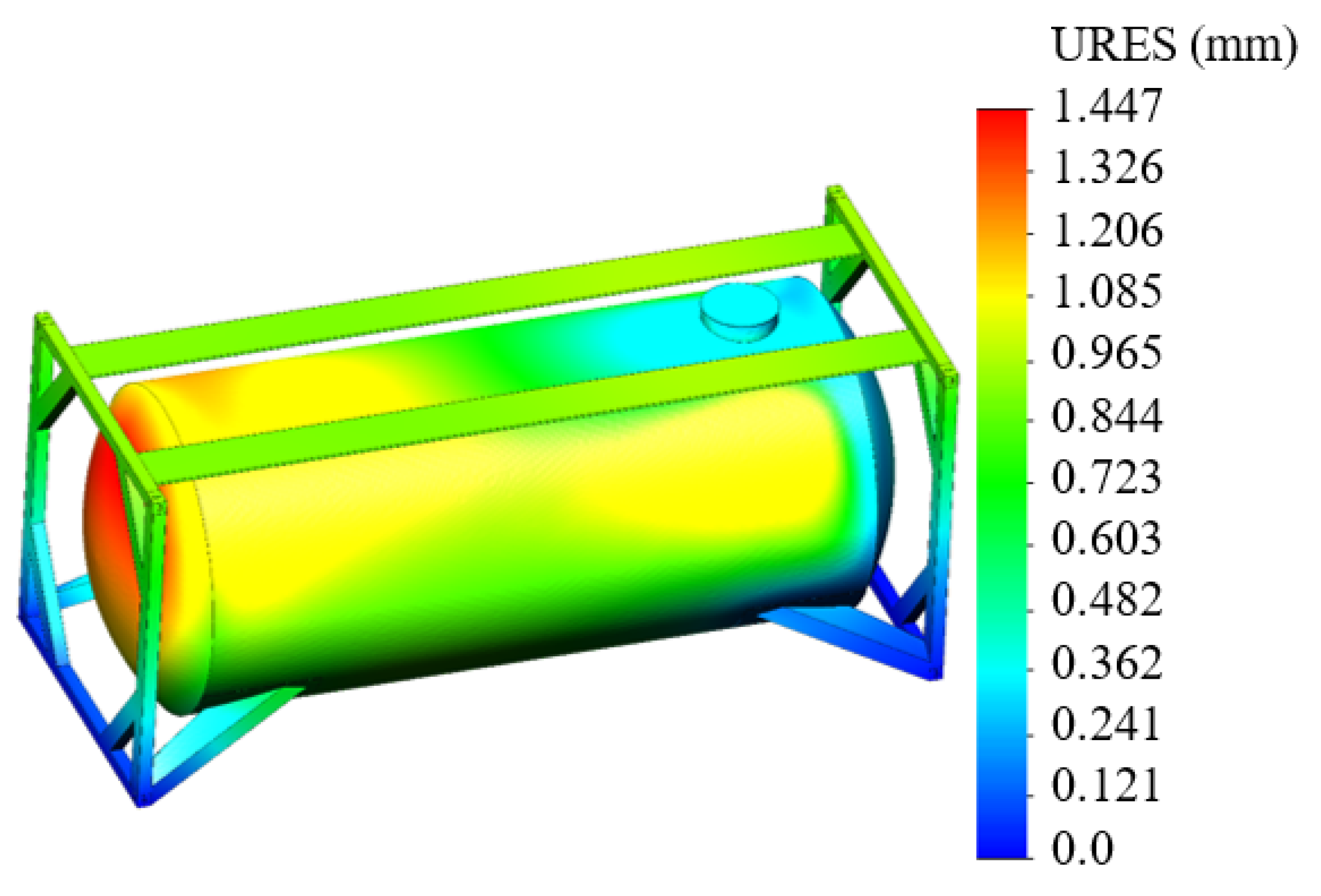
The largest displacements in the tank container structure occurred in the tank bottom located on the opposite side of the manhole (
Figure 11). These displacements were 1.4 mm.
As the next step, the modal analysis of the tank container was performed using the design diagram (
Figure 4) and the options of the SolidWorks Simulation software. The purpose of this calculation was to determine the first natural frequency (or eigenfrequency) of the tank container oscillations, which must be at least 8 Hz. This ensures the tank container traffic safety when transported by rail [
34].
The boundary conditions were assumed to be identical to those used for the calculation scheme shown in
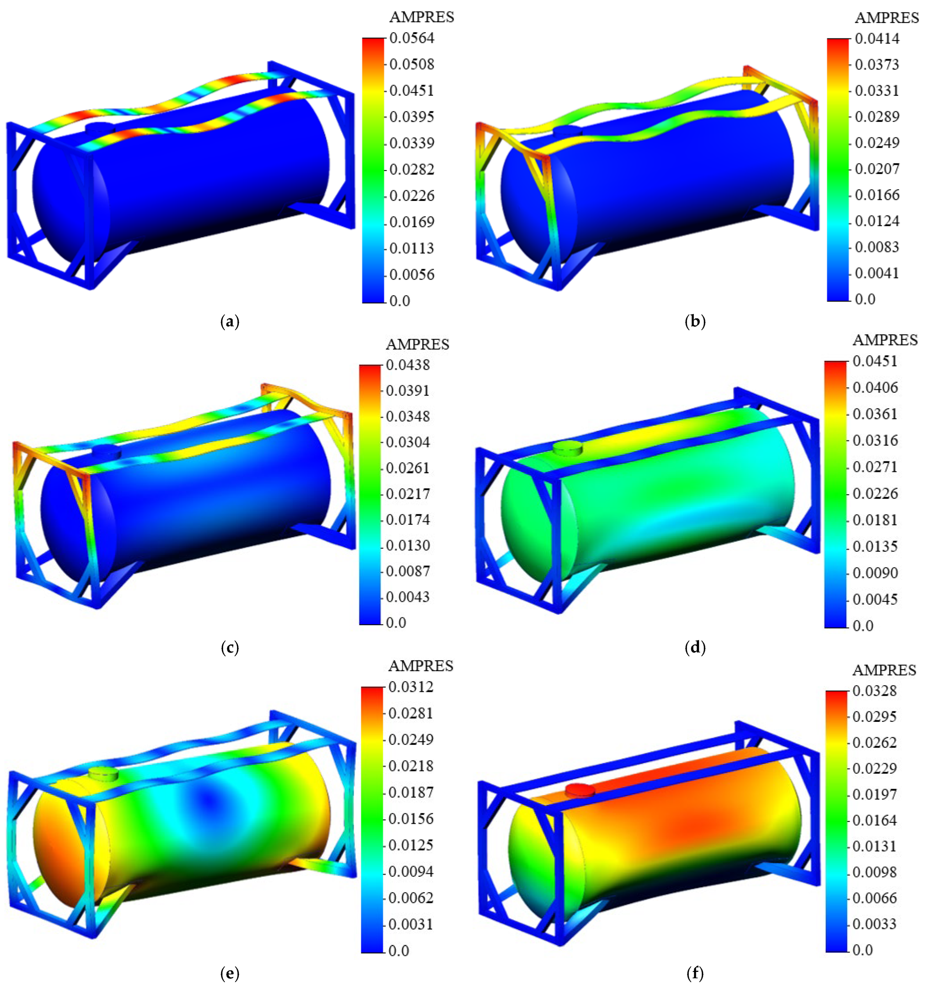
Figure 4. The selected eigenmodes of the oscillations of the tank container are shown in
Figure 12 in an enlarged scale (20:1). At the same time, conventional units, such as AMPRES, are used as the unit of amplitude measurement in the software. This unit reflects the relative vibration in different parts of the tank container and it is not an absolute physical quantity. It shows how much more strongly one part of the structure vibrates compared to another, and not the absolute displacement.
The values of the eigenfrequencies of the tank container are listed in
Table 4. Thus, at the first eigenmode, the maximum amplitude occurs in the transition area (
Figure 12a), while the eigenfrequency is about 13.8 Hz (
Table 4). For the second eigenmode, the maximum amplitude occurs in the corner parts of the end frames (
Figure 12b) at the eigenfrequency of 13.9 Hz. In the third eigenmode, the maximum amplitude is recorded in the upper part of the boiler (
Figure 12c). In this case, the eigenfrequency is 19.7 Hz. For the fourth eigenmode, the maximum amplitude occurs in the upper corner parts of the end frames (
Figure 12d). The eigenfrequency for this mode is 26.4 Hz. In the fifth eigenmode, the maximum amplitude is concentrated in the upper part of the boiler near the manhole (
Figure 12e). In this case, the oscillation eigenfrequency is 27 Hz. For the sixth eigenmode, the maximum amplitude is recorded in the lower part of the boiler bottom (
Figure 12f). For this mode, the eigenfrequency value is 27.9 Hz.
It can be concluded, based on the conducted analysis, that the safety of tank container transportation from the point of view of the modal analysis is ensured, because the first eigenfrequency is 13.8 Hz.
The main contribution of this research consists of a comparison of the designed tank container including sandwich panels with an existing technical solution of tank container structures. The results proved that the proposed tank container design leads to the reduction in the dynamic loads during operation and subsequently to the improved strength of its structure.
It should be emphasized that the most unfavorable loading mode of the tank container specified in the regulatory document [
8] was considered while conducting this study. As the proposed solutions have a positive effect for this operation mode, their feasibility is predicted for other schemes of longitudinal loading of the tank container during railway transportation (jerk, tension, compression). However, appropriate calculations will be carried out at the subsequent stages of work to confirm this hypothesis.
It is important to note that these studies were conducted under the conditions regulated by the standards [
8,
34]. Compared with the requirements of the standard [
50], the values of the loads acting on the flat wagon with tank containers are more severe. Therefore, it is supposed that the proposed implementation will also have positive results for a case study of the tank container loads under the condition of transportation on a 1435 mm gauge.
The limitations of this study were that the design model did not include the welds, and it was considered as a one-piece structure. The authors set the task of substantiating the concept of a tank container with sandwich components in the design. As far as the obtained result was positive, the next step in this field will be to determine the strength of the welds, and to study the load of the tank container transported by road and water transport.
It is planned to involve specialists in materials science in subsequent studies in this direction. This is due to the requirement of solving the issue of selecting an energy-absorbing material, the features of its interaction with the metal parts of the panel, etc. For example, foam aluminum can be used as an energy-absorbing material, which has proven itself quite well in mechanical engineering. Therefore, these studies will definitely be considered in the future.
Furthermore, the issue of studying the influence of swaying vibrations of bogies on the operation of sandwich panels in the tank container design can also be a continuation of this study [
51].
After completing the above-mentioned tasks, it is planned to conduct experimental studies of the proposed solution. Similar studies have already been carried out by the author’s team, and their results are highlighted in work [
52]. Therefore, an experimental study of the tank container strength of the proposed design will be conducted based on the formed “Program and Test Methodology”.
The obtained results will be useful for further designing and manufacturing modern tank containers.
4. Conclusions
1. A study of the longitudinal dynamic load of a tank container with sandwich components in the structure was carried out. It was considered that the energy-absorbing material included in the sandwich panel has different characteristics: elastic, viscous, and viscoelastic. The study was conducted under the condition of placing the tank container on a flat wagon during shunting collision. This load mode was the most unfavorable in terms of the force impact on the tank container during operation. Therefore, it was considered in the calculations. It was proved, based on the achieved results, that the application of sandwich components in a tank container helps to reduce the dynamic loads acting on it by 12 to 18%, depending on the characteristics of the energy-absorbing material.
A computer simulation of the dynamic load of the tank container was also carried out. The finite element method implemented in SolidWorks Simulation software was used. It was found that the maximum accelerations occur in the manhole and they are 36.5 m/s2. The built model was verified according to the F-criterion. The optimal number of experiments was determined using Student’s t-test. The calculations showed that the calculated value of Fisher’s exact test was 1.18, which does not exceed the tabulated value. Therefore, the hypothesis of the adequacy of the models is confirmed.
2. The strength of the tank container with sandwich components in the structure was calculated. The maximum stresses acting on the tank container were of 231.1 MPa. They were located in the manhole area. This distribution of stresses is explained by the fact that the manhole creates stress concentrations because it was located on the cylindrical part of the boiler on the side of longitudinal loads. It is important to note that the resulting stresses are lower than permissible by 25.6% and they are lower by 24% than those in the typical tank container design.
The largest displacements in the tank container were 1.4 mm and they occurred in the bottom of the boiler, which is located on the opposite side of the manhole.
The results of the modal analysis of the tank container make it possible to determine that the first natural oscillation frequency was 13.8 Hz. In this case, the maximum amplitude of oscillations was recorded in the transition area. Thus, the safety of the tank container transported in terms of modal analysis is observed.
