Abstract
Online radiation dose monitoring is critical for the safe operation of accelerators. Although commercial dose monitors are well-developed, integrating an ionization chamber directly within a small-sized Betatron magnet remains challenging. In this study, we designed an air ionization chamber tailored for real-time dose monitoring in a small-sized Betatron. We selected aluminum for the chamber wall based on structural and integration requirements, designed the cavity geometry, and developed the associated charge collection and sampling circuits. Using a standard reference PTW ionization chamber, we calibrated the output voltage of the chamber against X-ray dose rates and conducted stability tests. The results show that there is a very good linear relationship between the output voltage of the ionization chamber and the X-ray dose rate. The relative standard deviation of the dose rate data within a 10 min working cycle is 3.25%, and the dose rate data shows good consistency with the standard reference ionization chamber. The ionization chamber can ensure operational safety for a small-sized Betatron and offer guidance for similar applications.
1. Introduction
Electron accelerators are powerful tools capable of accelerating electrons to extremely high energies, producing high-energy X-rays through bremsstrahlung radiation. These electron beams have a wide range of applications in nuclear physics, industry, and medicine [1,2]. One type of electron accelerator, the Betatron, utilizes a changing magnetic field to generate an electric field that accelerates electrons [3]. Compared to linear accelerators [4,5], Betatrons do not require complex radio frequency, vacuum, and water cooling systems, making them more compact, lightweight, and easier to maintain. These characteristics makes Betatrons particularly suitable for container radiation imaging inspection and industrial non-destructive testing systems [6,7]. However, the magnitude and stability of the X-ray radiation dose or electron beam directly impact the quality of the resulting imaging or inspection output, making real-time radiation dose monitoring essential during operation [8,9].
Ionization chambers [10,11] are widely used for measuring radiation dose by detecting the ionization produced by X-rays in a gas medium. They are valued for their high accuracy and broad dose range and are commonly employed in both medical and industrial contexts [12,13]. To measure high-energy X-rays, air-equivalent ionization chambers are typically used. Among the conventional types, sleeve-type and thimble-type ionization chambers, such as the PTW 30013 Farmer-type and the C552 Shonka chamber, are designed for precise absolute dose measurements [14,15]. These chambers are usually positioned at fixed reference points and connected via cables to electrometers. Due to their configuration, they are not well-suited for real-time monitoring or for a small-sized Betatron.
In contrast, transmission-type ionization chambers, such as the PTW 7862, are optimized for real-time beam monitoring in accelerator systems [16,17]. Recognizing the need for a compact, integrated solution, our study aims to design and implement a small-volume, air ionization chamber tailored for real-time dose monitoring inside the magnet of a small-sized Betatron.
The small-sized Betatron developed in this work features a magnet with a diameter of 315 mm and a height of 380 mm [18], which imposes significant constraints on instrumentation placement. Traditional ionization chambers cannot be directly embedded within the magnet, necessitating the development of a dedicated monitoring system.
In this paper, we present the design and implementation of an online X-ray radiation dose monitoring system for small-sized Betatron applications. The system comprises a compact ionization chamber, a charge collection circuit, and signal processing modules. The proposed ionization chamber is embedded within the small-sized Betatron magnet and positioned directly in the path of the X-ray output port. Therefore, the ionization chamber is intended to monitor the primary X-ray beam, not leakage radiation. This configuration enables accurate and application-relevant monitoring of the X-ray dose corresponding to the primary beam used in Betatron imaging or irradiation applications.
To achieve reliable calibration and performance verification, the following measurable sub-objectives were established:
- Chamber design optimization: Determine the geometric dimensions, material selection, and electrode configuration to ensure reliable charge collection while maintaining compactness for integration within the Betatron magnet.
- Calibration and linearity verification: Establish the quantitative relationship between the chamber’s output voltage and the X-ray dose rate, with the correlation coefficient serving as a metric for linearity.
- Stability and repeatability assessment: Evaluate short-term relative standard deviation of dose measurements and compare the chamber’s readings with a standard PTW 30013 Farmer-type chamber to ensure measurement accuracy and consistency.
2. Materials and Methods
2.1. Ionization Chamber Parameters
The small-sized Betatron we developed produces X-rays with energy ranging from 2 MeV to 7.5 MeV [19]. For X-ray dose monitoring in the above energy range, we designed an air ionization chamber with the geometric structure shown in Figure 1. The ionization chamber mainly includes a cavity, a collecting electrode, a shield, a filter, and an insulating bakelite board.
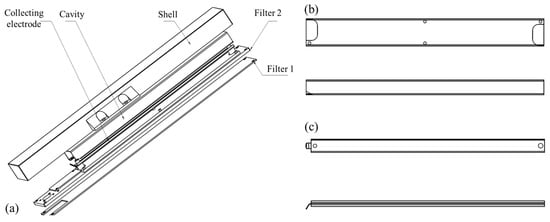
Figure 1.
Structure of ionization chamber: (a) Chamber geometry; (b) Cavity; (c) Collecting electrode.
The cavity and the collecting electrode are mounted on the filter sheet 2 through nylon support columns, and the cavity, the collecting electrode and the filter sheet 2 are insulated by bakelite. The specific design parameters of the ionization chamber are shown in Table 1.

Table 1.
Ionization chamber design parameters.
2.2. X-Ray Dose Calculation
In dosimetry terminology, the phrase “energy transferred by X-rays” is more accurately associated with KERMA (Kinetic Energy Released per unit MAss), while absorbed dose is defined as the energy actually deposited in the medium [20]. Therefore, in this work, exposure dose calculation can be expressed as shown in Equation (1) [21].
In Equation (1), Q represents the total collected charged (in Coulombs), D is the exposure dose in roentgen (R), m is the mass of air in the ionization chamber cavity (kg). Given that m = ρair·V, and ρair ≈ 1.293 kg/m3 under standard conditions [22], V is the volume of the ionization chamber cavity (m3). we can estimate:
The calculation avoids the use of outdated units such as roentgen (R), and instead directly expresses exposure dose in Gray (Gy) using the ratio of total collected charge to the air mass in the chamber, and then convert it through a standard coefficient. This approach is consistent with modern SI-based dosimetry protocols, including ICRU Report 90 and IAEA TRS-398 [21,23].
2.3. Charge Collection Circuit
The circuit is responsible for accurately measuring the small charge generated on the ionization chamber’s collector while minimizing noise and drift to ensure precise measurements. However, since the ionization charge formed on the collection electrode is very small, it is crucial to have a high input resistance in the charge collection circuit in order to accurately measure weak charge signals. Additionally, it is important to minimize noise and drift in order to ensure accurate measurements.
To address the issue of weak current measurement, we have implemented a method similar to that of a pulse amplifier, which utilizes an impedance conversion function in the circuit. This allows for a high input impedance and a low output impedance in the emitter follower. While it does not provide voltage amplification, it does serve the purpose of impedance conversion. The charge collection circuit we have designed is depicted in Figure 2.
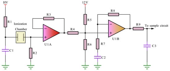
Figure 2.
Charge collection circuit.
In Figure 2, the ionization charge collected by the ionization chamber is converted into a voltage signal, which then passes through resistor R2. This voltage signal is then transformed by the input stage impedance and requires amplification by the amplifier stage. The input stage circuit utilizes an emitter follower configuration and employs junction field effect transistors to amplify weak current signals. Junction field effect transistors are preferred over other types of op amps due to their high input impedance, low noise, and good thermal stability.
The amplifier circuit is a common-mode proportional amplifier circuit. After passing through resistor R9 and capacitor C3, the signal is amplified and forms a pulse voltage signal. The pulse voltage can be seen in Equation (3).
In Equation (3), i(t) represents the current pulse output by the ionization chamber. The pulse voltage signal is transmitted to the sampling unit of the accelerator through a cable. Combining Equations (2) and (3), it is shown that the peak value of the pulse voltage is proportional to the radiation dose amount D, and the radiation dose can be calculated by measuring the voltage peak value.
2.4. Sampling Circuit
The ionization chamber is typically installed on the magnet of the accelerator. In order to minimize the effects of radiation, there is a specific distance maintained between the sampling unit of the accelerator and the ionization chamber. The ionization chamber produces an analog pulse voltage signal, which is then transmitted to the sampling unit through a cable. It is important for the amplitude of this analog signal to be as high as possible in order to minimize any loss of the pulse signal during transmission. To achieve this, the signal conditioning circuit is designed to limit the amplitude of the pulse voltage signal to the range of the analog-to-digital converter, as shown in Figure 3.

Figure 3.
Sampling circuit.
In Figure 3, Rp1 and R10 create a negative bias circuit. This circuit provides a bias voltage that can be used to detect whether the ionization chamber is connected. If the ionization chamber is not connected, the input voltage in the circuit is pulled down to −12 V. This allows for the identification of the ionization chamber being offline after sampling. The bias voltage can be adjusted using Rp1. The biased signal is then filtered to remove any interference on the line. This is achieved through a filter composed of R11 and C4. The filtered signal is then output to the adjustable resistor Rp2 through a common-phase proportional amplifier U2A. Rp2 is used to manually adjust the attenuation value of the voltage. The attenuated voltage signal then passes through D1 and D2 limiters before being input into the analog-to-digital converter through the isolation buffer U2B. The limiters ensure that the signal output to the analog-to-digital converter is between −0.7 V and 4 V. The converted digital quantity is then transmitted to the DSP for further digital processing.
3. Results and Discussion
3.1. Experiment Equipment
To verify the performance of the X-ray dose monitoring for the small-sized Betatron mentioned above, an ionization chamber and corresponding circuits were developed based on the geometric parameters of the chamber. The chamber is integrated into the accelerator’s magnet, with its vertical center aligned with the center of the X-ray beam. The installation diagram can be seen in Figure 4. The ionization chamber is connected to the accelerator’s control unit via a cable. A positive high voltage of 100 V is applied to the chamber’s cavity.

Figure 4.
Schematic diagram of ionization chamber installation structure: (a) Top view; (b) Front view; (c) Stereogram.
The test temperature was maintained at 26 °C, normal atmospheric pressure, the magnet heat dissipation adopted air-cooling mode, and the X-ray pulse frequency was 300 Hz. In addition, to ensure the stability of the accelerator output dose, the small-sized Betatron was preheated for more than 5 min before measurement. The ionization chamber and the installation position of the ionization chamber we actually developed are shown in Figure 5.
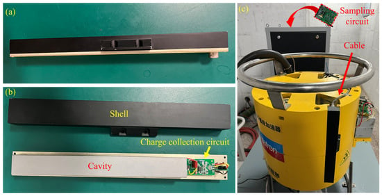
Figure 5.
Ionization chamber installation location and experimental platform diagram: (a) Side of the ionization chamber; (b) The structure of the ionization chamber; (c) Experimental facility.
In order to compare the dose monitoring data, the PTW Unidos dosimeter was used for experimental data comparison. The PTW Unidos dosimeter uses a 30013 ionization chamber with a Farmer-type chamber volume of 0.6 cm3 [14]. The ionization chamber is placed at a position 1 m away from the target on the horizontal plane of the X-ray beam axis.
3.2. Ionization Chamber Output Waveform
Figure 6 displays the waveform of the ionization chamber output at an X-ray energy of 7.5 MeV. As the ionization chamber collects charges, the voltage curve rises. Once it reaches its peak, the voltage gradually decreases as the capacitor discharges. The frequency of X-ray generation is 300 Hz, which means that the voltage waveform in Figure 6a also has a repetition frequency of 300 Hz. This means that every time the accelerator produces an X-ray pulse, the ionization chamber simultaneously outputs a voltage pulse. By measuring the peak value of each voltage pulse, the real-time X-ray dose rate can be calculated.
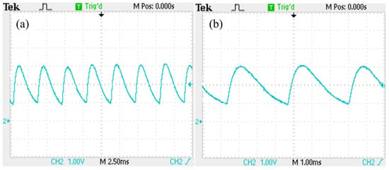
Figure 6.
Ionization chamber charge collection circuit output voltage waveform: (a) X-axis: 2.5 ms/div, Y-axis: 1 V/div; (b) X-axis: 1 ms/div, Y-axis: 1 V/div.
Figure 6b illustrates the integral characteristics of the voltage pulse output from the charge collection circuit. When a radiation pulse is generated, the circuit integrates the charge output of the ionization chamber through the process of ionization, causing the voltage to gradually increase. Once the voltage reaches its peak, it then begins to decay until it reaches the bias voltage position. This cycle repeats with each subsequent radiation pulse, resulting in a continuous output.
3.3. Calibration Test
The amount of charge generated by the ionization chamber is directly affected by the intensity of the X-rays. As the X-ray intensity increases, the peak value of the pulse voltage output by the ionization chamber also increases. This means that there is a linear relationship between the peak voltage and the X-ray intensity within a wide range.
For comparison and calibration, we used a PTW Unidos electrometer in conjunction with a PTW 30013 Farmer-type ionization chamber. The PTW 30013 chamber has a nominal sensitive volume of 0.6 cm3 and is widely used as a reference dosimeter in clinical and industrial settings.
Prior to use, the reference chamber was calibrated in terms of exposure dose following the IAEA TRS-398 protocol, under standard beam quality and environmental conditions [23]. This ensures traceability and reliability of the comparison between the proposed ionization chamber and the reference system. Simultaneously, we used an oscilloscope to record the voltage output from the ionization chamber charge collection circuit shown in Figure 2. The resulting graph in Figure 7 clearly illustrates the relationship between voltage and dose rate.
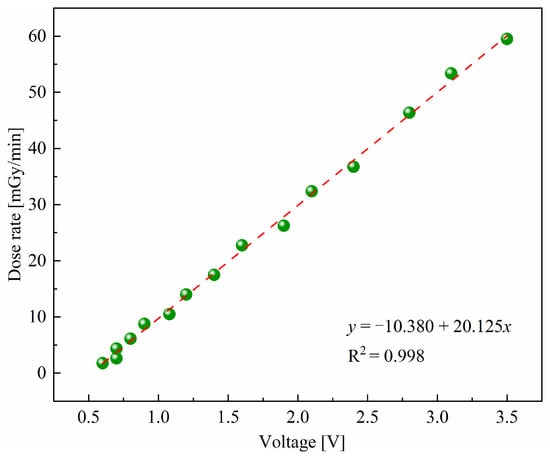
Figure 7.
The relationship between ionization chamber output voltage and dose rate.
The relationship between the ionization chamber output voltage Vout and the X-ray dose rate D was evaluated and plotted in Figure 7. The experimental points follow the expected linear behavior according to the charge collection principle, as described in Equations (2) and (3). A linear regression was performed, with a correlation coefficient R2 = 0.998. The slope represents the conversion coefficient from voltage to dose rate, confirming a strong linear relationship. The voltage peaks of the chamber can thus be directly converted into X-ray dose rates in real time.
3.4. Dose Rate Test
To assess the long-term stability of the ionization chamber, a stability test was conducted. Due to the direct air-cooling system used by the accelerator magnet, the accelerator can only operate continuously for a maximum of 10 min. During the test, the X-ray dose rate was recorded from the ionization chamber every 30 s. The results of the dose rate test are presented in Figure 8.
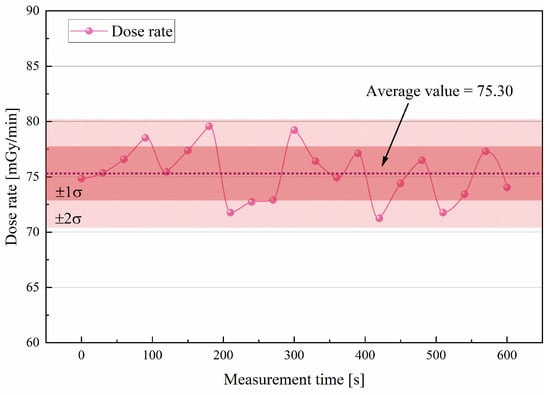
Figure 8.
Dose rate test data.
In Figure 8, the upper limit of the dose rate test data is 79.56 mGy/min, the lower limit is 71.24 mGy/min, the average is 75.30 mGy/min, the standard deviation is 2.45, and the relative standard deviation is 3.25%. During the 10 min working cycle of the accelerator, the maximum fluctuation range of the X-ray dose rate data measured by the ionization chamber did not exceed 11% of the average value. It is important to note that the accelerator dose is not always stable, and the data can reflect the changes in the monitored dose by the ionization chamber.
The error band in Figure 8 and all related point-line plots represent the standard deviation derived from three independent measurements for each dose rate level. The error bands now represent ±2σ, reflecting 95% confidence in the measurement variation. The variations are attributed to measurement fluctuations and instrument precision, and are within acceptable bounds for relative monitoring applications. The inclusion of error bars highlights the repeatability and reliability of the measurement system. These results indicate that the chamber reliably tracks real-time fluctuations in the X-ray dose, consistent with expected behavior.
Figure 9 illustrates the correlation between the dose rate and the ratio of the dose rate at various energies to the dose rate at the peak energy, with the electron energy ranging from 2 to 7.5 MeV.
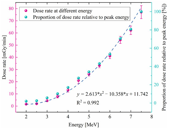
Figure 9.
The relationship between dose rate and energy.
As shown in Figure 9, the dose rate generated by the accelerator increases gradually as the energy increases. The dose rate value exhibits a gentle nonlinear relationship with the X-ray energy. In the energy range of 2 MeV to 7.5 MeV, the proportion of Compton scattering and electron pair effect will vary. The close agreement between the experimental points and the fitted curve confirms that the chamber responds as theoretically expected across the energy range.
Theoretically, the X-ray yield from a Betatron increases approximately with the square of the electron energy due to the bremsstrahlung process. Therefore, the dose rate is expected to follow a quasi-quadratic trend with increasing energy. The experimental data in Figure 9 exhibit a similar nonlinear rising trend, consistent with this theoretical expectation, confirming that the developed ionization chamber accurately reflects the physical variation in dose rate with energy.
3.5. Comparison Between PTW Ionization Chambers
To assess the effectiveness of the ionization chamber, a comparison was conducted with a commercial ionization chamber from the PTW. Both instruments were measured under identical conditions, with a sampling time of 30 s. Figure 10 displays the measurement data from the ionization chamber and the PTW instrument for comparison.
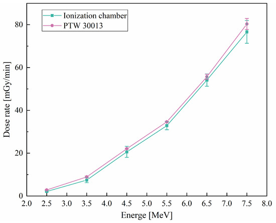
Figure 10.
Dose data comparison between PTW 30013 ionization chamber.
Figure 10 is primarily intended to demonstrate the consistency between the developed ionization chamber and the commercial PTW 30013 chamber under identical conditions, rather than to model a specific mathematical dependence. Therefore, instead of introducing fitting functions, we focus on highlighting the strong correlation and acceptable deviation between the two instruments, which effectively verifies the reliability of the developed ionization chamber for real-time X-ray dose monitoring applications.
The results demonstrate a strong similarity between the dose data obtained by the two instruments. Across the measured X-ray dose rates, the commercial dosimeter readings are consistently approximately 5% higher than those of the developed ionization chamber. Despite this systematic offset, the correlation between the two systems remains excellent, and the ±5% difference is acceptable for online industrial dose monitoring, which prioritizes real-time relative measurements rather than absolute clinical dosimetry.
It should be noted that our developed ionization chamber may have inferior repeated measurement stability compared to the commercial PTW ionization chamber. However, it is important to consider that the PTW ionization chamber is primarily used for dose monitoring in radiotherapy, while our Betatron is primarily used in the field of radiation imaging. Therefore, the measurement stability has met the requirements.
The observed differences between the proposed ionization chamber and the PTW reference system can be attributed to several factors. First, the PTW 30013 Farmer-type chamber is designed for absolute dose measurements in clinical conditions, with a well-established calibration traceable to water phantom protocols. In contrast, our proposed chamber is optimized for real-time relative monitoring within a small-sized Betatron and was calibrated using empirical fitting against the PTW reference system.
Second, the differences in detector geometry and charge response time introduce small but measurable variations in recorded dose rate. The proposed ionization chamber, being structurally embedded inside the Betatron, may also experience slight positional or alignment deviations during manufacturing and assembly.
Nonetheless, the correlation between the two systems remained strong, and the dose rate deviation was within ±5%, which is acceptable for online industrial dose monitoring. This validates the reliability of the proposed system for practical application, despite its different design purpose compared to clinical-grade dosimeters.
4. Conclusions
In this study, we successfully designed and implemented a compact air ionization chamber for online X-ray dose monitoring in a small-sized Betatron. The system comprises a chamber with tailored geometry, charge collection circuits, and signal sampling modules, enabling real-time measurement of X-ray dose rates. Calibration against the PTW 30013 Farmer-type ionization chamber demonstrated excellent linearity and stability, with a linear correlation coefficient of R2 = 0.998, validating the reliability of the developed system. The main scientific and technical advancements achieved in this work include:
- Integration feasibility: Demonstrated that a dose monitor can be embedded directly within the confined space of a small-sized Betatron magnet, addressing significant design and space constraints.
- Calibration methodology: Developed a quantitative relationship between chamber voltage output and X-ray dose rate, providing a practical approach for real-time monitoring in industrial X-ray applications.
- Performance verification: Confirmed that the proposed ionization chamber can provide dose measurements consistent with a commercial reference system, ensuring safe operation and supporting imaging or irradiation tasks.
Despite these achievements, the study has some limitations. The stability of the developed chamber is slightly lower than that of clinical-grade dosimeters, though still sufficient for industrial monitoring purposes. The design is specifically optimized for a small-sized Betatron and may require modification for other accelerators or higher-energy X-rays.
For future work, efforts will focus on further improving stability and noise reduction, extending the applicability of the chamber to other accelerator platforms and broader X-ray energy ranges, and performing long-term operational tests to ensure reliability in extended industrial use.
In conclusion, this work provides a practical and validated solution for real-time dose monitoring in small-sized Betatron accelerators, contributing to safer operation and offering guidance for similar applications in compact accelerator systems.
Author Contributions
Conceptualization, B.Z. and S.Z.; methodology, B.Z.; validation, Y.Z.; formal analysis, W.Z.; investigation, T.Y.; resources, H.W.; data curation, W.Z.; writing—review and editing, B.Z. and Q.L.; visualization, Y.Z.; supervision, Q.L.; project administration, H.W.; All authors have read and agreed to the published version of the manuscript.
Funding
This research was funded by National Natural Science Foundation of China (No. 42374226), Key Research and Development Project of Jiangxi Province (No. 20232BBE50013), Jiangxi Provincial Natural Science Foundation (No. 20243BCE51132 and No. 20252BAC200169), National Key Laboratory of Uranium Resource Exploration-Mining and Nuclear Remote Sensing (No. 2024HDX10).
Institutional Review Board Statement
Not applicable.
Informed Consent Statement
Not applicable.
Data Availability Statement
The original contributions presented in this study are included in the article. Further inquiries can be directed to the corresponding author.
Conflicts of Interest
The authors declare no conflicts of interest.
References
- Jeong, D.H.; Lee, M.; Lim, H.; Kang, S.K.; Lee, S.J.; Kim, H.C.; Lee, K.; Kim, S.H.; Lee, D.E.; Jang, K.W. Electron beam scattering device for FLASH preclinical studies with 6-MeV LINAC. Nucl. Eng. Technol. 2021, 53, 1289–1296. [Google Scholar] [CrossRef]
- Lee, S.H.; Shin, S.W.; Lee, J.; Kim, H.S.; Lee, B.N.; Lee, B.C.; Park, H.; Song, K.; Song, H.; Mun, S.; et al. X-band Linac for a 6 MeV dual-head radiation therapy gantry. Nucl. Instrum. Methods Phys. Res. Sect. A Accel. Spectrom. Detect. Assoc. Equip. 2017, 852, 40–45. [Google Scholar] [CrossRef]
- Kerst, D.W. Acceleration of electrons by magnetic induction. Phys. Rev. 1940, 58, 841. [Google Scholar] [CrossRef]
- Masoumi, M.; Masoudi, S.F.; Rahmani, F. Design and optimization of thermal neutron activation device based on 5 MeV electron linear accelerator. Nucl. Eng. Technol. 2023, 55, 4246–4251. [Google Scholar] [CrossRef]
- Zhu, Y.; Yuan, P.; Cao, S.; Liu, M.; Zong, Y.; Zhao, Q.; Zhang, J.; Shen, X.; Zhang, Z. Design and simulation of a LINAC for high energy electron radiography research. Nucl. Instrum. Methods Phys. Res. Sect. A Accel. Spectrom. Detect. Assoc. Equip. 2018, 911, 74–78. [Google Scholar] [CrossRef]
- Kutsaev, S.; Agustsson, R.; Arodzero, A.; Boucher, S.; Hartzell, J.; Murokh, A.; O’Shea, F.; Smirnov, A.Y. Electron accelerators for novel cargo inspection methods. Phys. Procedia 2017, 90, 115–125. [Google Scholar] [CrossRef]
- Karikh, V.P.; Kodolov, A.V.; Okhotnikov, A.A.; Skokov, A.A. A betatron tomograph for nondestructive testing of products with a diameter up to 1000 mm made of high-energy materials. Russ. J. Nondestr. Test. 2019, 55, 322–327. [Google Scholar] [CrossRef]
- Kim, H.; Jeong, D.H.; Kang, S.K.; Lee, M.; Lim, H.; Lee, S.J.; Jang, K.W. Real-time monitoring of ultra-high dose rate electron beams using bremsstrahlung photons. Nucl. Eng. Technol. 2023, 55, 3417–3422. [Google Scholar] [CrossRef]
- Agassy, F.O.; Park, J.I.; Kim, I.J. Development of a device to improve the precision of water surface identification for MeV electron beam dosimetry. Nucl. Eng. Technol. 2024, 56, 1431–1440. [Google Scholar] [CrossRef]
- Nariyama, N. Multi-concentric-ring open-air ionization chamber for high-intensity X-ray beams. Nucl. Instrum. Methods Phys. Res. Sect. A Accel. Spectrom. Detect. Assoc. Equip. 2014, 763, 13–17. [Google Scholar] [CrossRef]
- Almond, P.R.; Svensson, H. Ionization chamber dosimetry for photon and electron beams. Acta Radiol. Ther. Phys. Biol. 1977, 16, 177–186. [Google Scholar] [CrossRef] [PubMed]
- Matsubayashi, N.; Hu, N.; Takata, T.; Sasaki, A.; Nojiri, M.; Mukawa, T.; Sakurai, Y.; Tanaka, H. Air ionization chamber combined with LiCaAlF6 scintillator for γ-ray dose evaluation in boron neutron capture therapy. Nucl. Instrum. Methods Phys. Res. Sect. A Accel. Spectrom. Detect. Assoc. Equip. 2023, 1047, 167883. [Google Scholar] [CrossRef]
- Takata, N. A free-air ionization chamber with a large aperture diaphragm. Nucl. Instrum. Methods Phys. Res. Sect. A Accel. Spectrom. Detect. Assoc. Equip. 2010, 619, 216–220. [Google Scholar] [CrossRef]
- PTW. Farmer Ionization Chamber 30013 Specifications. Available online: https://www.ptwdosimetry.com/en/products/farmer-ionization-chamber-30013-waterproof (accessed on 2 July 2024).
- Kim, I.J.; Kim, B.C.; Yi, C.Y.; Shimizu, M.; Morishita, Y.; Saito, N. Bilateral comparison of the absorbed dose to water in high energy X-ray beams between the KRISS and the NMIJ. Nucl. Eng. Technol. 2020, 52, 1511–1516. [Google Scholar] [CrossRef]
- PTW. X-Ray Therapy Monitor Chamber 7862 Specifications. Available online: https://www.ptwdosimetry.com/en/products/x-ray-therapy-monitor-chamber-7862 (accessed on 2 July 2024).
- Hou, B.; Yi, L.Y.; Hu, D.H.; Luo, Z.C.; Gao, D.Y.; Li, C.; Xing, B.W.; Wang, J.W.; Lee, C.N.; Zhang, R.; et al. A swallowable X-ray dosimeter for the real-time monitoring of radiotherapy. Nat. Biomed. Eng. 2023, 7, 1242–1251. [Google Scholar] [CrossRef] [PubMed]
- Liu, Q.; Wang, R.B.; Li, J.H.; Wang, H.T.; Chen, H.S.; Tang, B. Simulation analysis and experiment of magnetic pole shape influence on betatron magnetic field. Nucl. Technol. Radiat. Prot. 2022, 37, 1–10. [Google Scholar] [CrossRef]
- Liu, Q.; Li, J.H.; Wang, H.T.; Zhang, Y.; Chen, H.S.; Wang, R.B.; Zhou, S.M. Development of a pulsed magnetic field power supply for small size Betatron. Nucl. Eng. Technol. 2025, 57, 103125. [Google Scholar] [CrossRef]
- Attix, F.H.; Vergne, L.D.L.; Ritz, V.H. Cavity ionization as a function of wall material. J. Res. Natl. Bur. Stand. 1958, 60, 235–243. [Google Scholar] [CrossRef]
- Seltzer, S.M.; Fernandez-Varea, J.M.; Andreo, P.; Bergstrom, P.M.; Burns, D.T.; Krajcar Bronić, I.; Ross, C.K.; Salvat, F. Key Data for Ionizing-Radiation Dosimetry: Measurement Standards and Applications; ICRU Report 90; Oxford University Press: Bethesda, MD, USA, 2016; Available online: http://fulir.irb.hr/id/eprint/3302 (accessed on 10 September 2023).
- Wyckoff, H.O.; Attiix, F.H. Design of Free-Air Ionization Chambers; United States Department of Commerce: Washington, DC, USA, 1957; pp. 1–15.
- International Atomic Energy Agency. IAEA Technical Reports Series No. 398: Absorbed Dose Determination in External Beam Radiotherapy; IAEA: Vienna, Austria, 2000; pp. 15–56. [Google Scholar]
Disclaimer/Publisher’s Note: The statements, opinions and data contained in all publications are solely those of the individual author(s) and contributor(s) and not of MDPI and/or the editor(s). MDPI and/or the editor(s) disclaim responsibility for any injury to people or property resulting from any ideas, methods, instructions or products referred to in the content. |
© 2025 by the authors. Licensee MDPI, Basel, Switzerland. This article is an open access article distributed under the terms and conditions of the Creative Commons Attribution (CC BY) license (https://creativecommons.org/licenses/by/4.0/).