Abstract
Tunnels excavated in weak ground can develop problems due to squeezing phenomena. This situation is much more critical in large-diameter and double-tube tunnels. The effects of the tubes on each other are also important. The NATM (New Austrian Tunneling Method) is employed in the design of the support systems for these types of tunnels, which is based on the flexible outer arch principle and allows for deformations or minimization of deformations by increasing the lining thickness and using a rigid pavement. The risk of deformations occurring in a flexible outer arch is determined by the occurrence of deformations in shallow tunnels, which can affect the surface; a ground reaction curve can quickly develop and lead to a collapse. It is also known that the stability of the tunnel whose support and excavation is completed first can be impacted by subsequent excavations for the other tunnel. The purpose of the present study was to describe the geological and geotechnical conditions of a shallow tunnel excavated in weak ground and to assess its stability using three-dimensional numerical analysis. For this purpose, the Cukurcayir 1 tunnel—a double-tube tunnel—was employed as a case study. The 3D numerical analyses were performed using the Flac3d V2.10-222 software. The results are discussed in detail and recommendations for the necessary support system for tunnel roof and face stability are given.
1. Introduction
The problems encountered in tunnels excavated in weak ground generally occur in the tunnel roof and face. For this reason, the stability of the face and roof is very important for tunnel stability. This problem has been examined by various researchers through different case studies [1,2,3,4,5,6]. In large-diameter double-tube tunnels, the impact of the distance between two tubes causes stability problems in their support systems. In general, the distance between two tunnels is recommended to be at least 1.5 times the tunnel diameter [7]. However, this distance is often not possible due to topographic and surface constraints.
There are two main approaches in the design of support systems in weak ground. The first is an active support system approach that does not allow deformations. The other is a passive approach that allows deformations to occur in the tunnels in a controlled manner to maintain tunnel stability [8]. For this purpose, Shubert [9] suggested deformation gaps on the steel supports in tunnel support systems. This method was used in the Bolu mountain tunnels in fault zones [10]. In addition, Hoek [11] proposed sliding steel supports (TH) in sections when deformations occur and applied this approach in the Jacombu tunnel. These deformations are within the tolerance limits and do not damage the tunnel lining. However, the main problem here is that deformation curves rapidly develop in squeezing ground, which can also cause excessive deformation.
Sharifzadeh et al. [12] used the sequence excavation method in the Shibli tunnel that was constructed in weak ground and performed a back analysis. In this study, they highlighted the importance of both deformation measurements in tunnels and monitoring systems. Klopcic et al. [13] studied displacement during the tunnel excavation progress in the Sentvid tunnel. They focused on the deformations of the rock masses in the tunnel under low overburden heights in a populated area. They found that the support system’s capacity is related to the foliation orientation in the rock mass. Ozsan and Basarir [14] investigated the support capacity of diversion tunnels excavated in weak rock masses using analytical and numerical methods. Do et al. [15] examined the behavior of a tunnel excavation method using 2D and 3D numerical analyses. Han et al. [16] carried out 3D numerical analyses of double-tube tunnels excavated in weak and blocky rocks using the umbrella arch support method. They found that the deformations remained stable and the safety factor increased by 2.25 times. Marinos [17] studied the tunnel behavior and the support relationship in tunnels excavated in a flysch series with weak rock mass properties. He emphasized that flysch series have heterogeneous and tectonically disturbed structures, leading to a low strength. He also emphasized that the support demands range from light support to very rigid support under high squeezing conditions. Vlachopoulos et al. [18] investigated the effect the tubes in double-tube tunnels on each other using two- and three-dimensional analyses.
It is known that, due to the rapid development of deformation and support reaction curves in weak ground, the loads acting on the support systems can increase suddenly and result in failure. If the deformation tolerance decreases quickly due to the incoming load and the lack of arching around the tunnel, it can cause support failure. In addition, the passive approach is not recommended in shallow tunnels excavated in weak ground as it may directly damage the buildings on the surface. It is imperative to build support systems using the active approach for deep tunnel sections in ground that is weak and squeezed. In these sections, deformations can develop very rapidly due to the high velocity of displacements due to high in situ stresses.
It has been revealed that utilizing a flexible outer arch support design, according to the principles of the NATM (New Austrian Tunneling Method), in tunnels excavated in weak ground is not suitable and an alternative is needed [10,19,20]. Many researchers believe that a rigid lining is required in weak ground and that the support systems in such ground should not allow deformations [21,22,23,24,25]. The supports should be placed immediately after the tunnel excavation and loosening should not be allowed around the tunnel. The deformations occurring along the tunnel profile, the plastic zones around the tunnel [26,27,28], and the ground reaction curve (GRC) and support reaction curve (SRC) for the tunnel support systems are important considerations in the placement and timing of the placement of the support systems.
To determine the most economical support systems, it is critical to determine the deformation tunnel interactions and the deformation tolerance in order to determine the optimal dimensions. If the deformations develop very quickly, they can cause the support systems to fail. If the support systems are designed to not allow any deformation, the support systems would be rigid. In weak ground, the rapid development of deformations makes the selection of the support system even more important.
Dong et al. [29] proposed a computational method to determine the surface settlements in parallel tunnels in layered rock medium. Huang et al. [30] investigated the surface settlements in twin-tube TBM tunnels due to different construction methods. Kumar and Jain [31] investigated the elastoplastic soil settlement response and stability of single and twin circular tunnels and the effects of tunnel depth, diameter, spacing and soil properties, and suggested stability conditions and support placement timing predictions that can be used in engineering designs. Zhang et al. [32] used 3D numerical simulation and field measurements to investigate the ground deformation properties and stresses acting to segments during the excavation of a shallow twin tunnel of Guangzhou Metro Line 18. Jamshasb and Shahrbabaki [33] investigated the effect of tunnel convergence in shallow twin tunnels and presented simplified relations to help tunnel designers find the optimum tunnel center-to-center distance. Guo et al. [34] establishes a theoretical decision model based on the Mohr–Coulomb failure criterion of the middle load-bearing column to determine the safe clear distance for shallow twin TBM tunnels and validates this model with numerical simulations. The three-dimensional numerical model of the Guanyin Mountain tunnel portal section was constructed by the Rhino, AutoCAD, and FLAC 3D software, and the whole construction process of the tunnel portal was simulated by Lit et al. [35]. Mirsepahi et al. [36] employed 3D finite element analyses for investigation of the performance of parallel hypothetical twin tunnels constructed in weathered residual soil using the New Austrian Tunneling Method (NATM). Another 3D analysis simulating the surface settlement due to twin-tunnel excavations was performed by Yu Huat et al. [37]. In addition to these studies, in the recent literature, many 3D numerical analyses have been performed on the twin-tunnel constructions [38,39,40,41].
The construction of the Cukurcayir 1 tunnel requires extreme care because it is located in an urbanized area, in weak ground, and has a low overburden thickness. In addition, it is very important to determine the best support systems since it is a twin tunnel and the tunnel excavation cross-section area is large (up to 200 m2). The ground reaction curve (GRC) and support reaction curve (SRC) were drawn for the Cukurcayir 1 tunnel and its tunnel support systems were assessed by performing 3D analyses using the Flac3d software. The numerical analysis results were compared with the measured deformation results in the tunnel. This tunnel is an interesting case study for underground construction work in residential areas. In addition, Wang et al. [42] stated that the temporal and spatial effects of a complicated excavation process are vital for an ultra shallow buried large-span double-arch tunnel excavated under an expressway in service, and numerical simulations are urgent and necessary to understand the effect of the total construction process. When considering this statement [42], the importance of the present study is clarified. Consequently, it is expected that shallow tunnel constructions in urban areas will increase due to population growth. The results of the present study will contribute to the safe construction of future shallow tunnels in urban areas.
2. Properties of the Cukurcayir 1 Tunnel
The Cukurcayir 1 tunnel is within the scope of the Trabzon City (NE Turkiye) Pass Project, wherein the right tube is between Km:11 + 660.45 and 11 + 980, and the left tube is between Km:11 + 661.25 and 12 + 040. The tunnel length is 379.25 m for the left tube and 319.25 m for the right tube. The tunnel overburden thickness is 40 m at the deepest section. A map showing the location of the tunnel is given in Figure 1. The Cukurçayir 1 tunnel was designed as a double tunnel with three lanes. The final height and width of the tunnel are 8.4 and 12.5 m, respectively. The tunnel excavation width is 17 m, and the height is 13.5 m. A typical cross-section of the tunnel is given in Figure 2 [43].
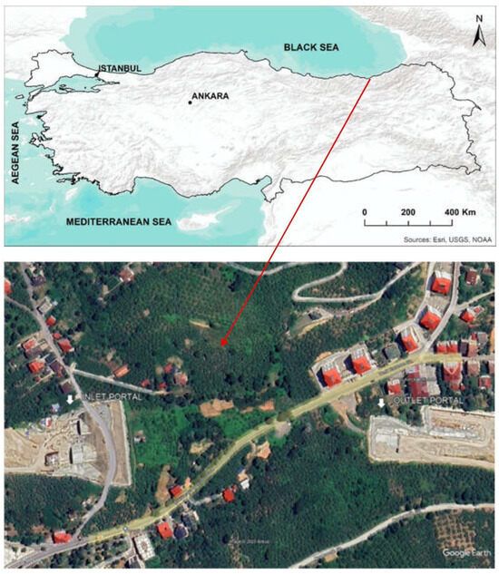
Figure 1.
Location of the Cukurçayir 1 tunnel.
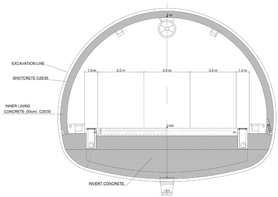
Figure 2.
Typical cross-section of the Cukurcayir 1 tunnel. Reprinted with permission from Ref. [43]. 2025, General Directorate of Highways.
In order to determine the geological and geotechnical conditions of the Cukurçayir 1 tunnel, a total of 6 boreholes with a depth of 35 to 50 m were drilled by the General Directorate of Highways of Turkiye. The necessary soil mechanics tests were performed on the specimens obtained from the boreholes and the material strength parameters were obtained. In addition, pressure meter tests were carried out in the boreholes and the elasticity modulus of the soil was calculated. During the field studies, yellowish brown-reddish brown clay, sandy silty clay, and clay/gravel units were encountered on the surface of the tunnel entrance portal and its vicinity. After the interpretation of the geological map and borehole data, a geological model of the Cukurçayir 1 tunnel was produced, which is shown in Figure 3 [44]. Clayey sand and weakly cemented sandstone, claystone, and tuff under the clay unit were observed on the surface. Figure 4 shows a geological cross-section of the tunnel.
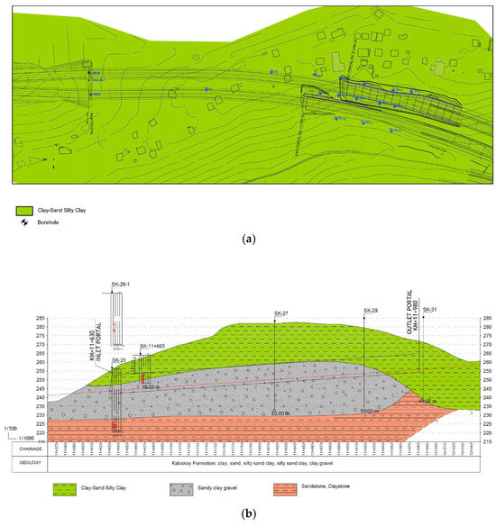
Figure 3.
Plan (a) and geological cross-section (b) of the Cukurcayir 1 tunnel. Reprinted with permission from Ref. [44]. 2025, General Directorate of Highways.
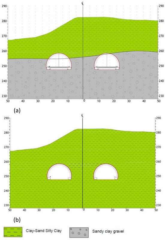
Figure 4.
Geological cross-sections at Km:11 + 972 (a) and Km:12 + 040 (b). Reprinted with permission from Ref. [44]. 2025, General Directorate of Highways.
Thus, it was found that the entire tunnel passes through clay and gravelly clayey sand units. A sample of the cores taken from the SK-26 borehole in the tunnl is presented in Figure 5. The samples revealed that the tunnel passes through clayey sandy units.
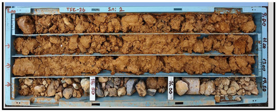
Figure 5.
Core samples obtained from SK-26 borehole.
According to the triaxial compression (UU) test results, the average undrained shear strength value was cu = ~50 kPa. This value is somewhat low, due to the sample not being saturated and due to the disturbance. In the standard penetration test (SPT) performed on the clay units in the SK-26 borehole, the test values ranged from N = 14 to 20. If the mean N value was set as 17, the corrected SPT value was N60 = 0.75 × 17 = ~13, according to the method of Stroud and Butler [45]. The average plasticity index value from the Atterberg experiments on clay units can be approximated as PI = ~23%.
After accepting the average values of N60 = 13 and PI = 23, the undrained shear strength value was calculated to be cu = 5 × 13 = 65 kPa for the short-term. In addition, Atterberg limit tests were carried out on the clay unit. Using the PI (%) values obtained from the experiments, the long-term parameters for the clay levels were calculated [46]. According to the Atterberg limit values obtained from the undisturbed borehole samples, the average PI value for the unit was 23%, and the effective friction angle value was determined from the PI value using the equation presented in Terzaghi et al. [46]. The PI value was found to be 23, and the effective friction angle (Ø) was determined to be approximately 29°. The cohesion value was predicted to be approximately 5 kPa. In the gravelly clay sand unit, the cohesion was predicted to be 5 kPa and the internal friction angle was 32°. The parameters of the soil materials are summarized in Table 1.

Table 1.
Geotechnical parameters of the lithological units.
3. Evaluation of the Squeezing Conditions
Since the tunnel section mainly passes through the clayey unit, the squeezing conditions in this unit were examined. The methods of Jethwa et al. [47] and Hoek and Marinos [40] were used.
Although originally proposed for rock masses, the criteria of Jethwa et al. [47] and Hoek and Marinos [48] were used here for comparative purposes to illustrate the similar compaction tendencies observed in overconsolidated or weakly clayey formations. To ensure conceptual consistency, soil-specific approaches (e.g., Anagnostou and Kovári [49]; Mair and Hight [50]) were also considered.
Jethwa et al. [47] classified the degree of compression depending on the ratio of the compressive strength of the rock mass to the in situ stresses. In Equation (1), the formula for compressive strength is given.
where σcm is the uniaxial compressive strength of the rock mass, h is the height, and γ is the unit weight.
According to Jethwa et al. [47], squeezing conditions is divided into 4 main categories: if the Nc value is less than 0.4, it indicates a high squeezing level; an Nc value between 0.4 and 0.8 indicates moderately squeezing behavior; an Nc value between 0.8 and 2.0 indicates mildly squeezing behavior; and if the Nc value is greater than 2.0, it indicates non-squeezing behavior.
Hoek and Marinos [48] defined squeezing based on the relationship between the compressive strength of the rock mass and the in situ stresses. Here, strain is given by Equation (2).
The squeezing status was determined according to Jethwa et. al. [47] and Hoek and Marinos [48], and is summarized in Table 2. According to Jethwa et.al. [47], the degree of squeezing was determined to be high, and according to Hoek and Marinos [48], severe squeezing problems were revealed. According to Hoek and Marinos [48], the support systems should be placed quickly, and the construction quality should be carefully controlled.
Table 2.
Evaluation of the squeezing conditions.
Evaluation of the Tunnel Support System Using Analytical Methods
The most important factors to be considered in weak ground tunneling are the plastic zone thickness and the deformations in the tunnel face. In addition, the behavior of the ground surrounding the tunnel is one of the most important factors in the design of the tunnel support system. In the design of the tunnel support system, the tunnel overburden thickness (h), the deformation modulus of the lithological unit (Em), the strength parameters (c, ϕ and υ), and the tunnel radius (r) are important parameters. It is necessary to calculate plastic deformations (uip), plastic zone radius (rp), elastic deformations (uie), and critical tunnel pressure (pcr) that may occur in the tunnel under unsupported conditions. Closed-form equations are commonly used for these calculations, which are explained in more detail by Hoek and Brown [26] and Hoek [27] and are summarized in Table 3. In these calculations, it was assumed that the tunnel is circular and under hydrostatic stresses and that the soil is isotropic. The Mohr–Coulomb failure criterion was used as the failure criterion. In the selection of the support system of the tunnel, a general analysis was performed by examining the closed-form equations to check the tunnel and the ground interaction behavior.
Table 3.
Closed-form solution equations [26,27].
Another important factor is the displacements occurring in front of and behind the tunnel face. Panet and Guenot [51], Panet [52], Unlu and Gercek [53], Carranza-Tores and Fairhust [54], Vlachoplous and Diedrichs [55], and Oke et al. [56] have conducted studies on the installation and timing of installation of support systems. The soil reaction curve (GRC) and support system curves (SRCs) should be determined, which are then used to determine the deformations that will occur and the correct time to apply the supports. The determination of the deformations in the tunnel face immediately after excavation is a critical step. If a high amount of deformation is allowed, situations that cause collapse in the tunnel may be encountered due to the rapid development of deformations in the ground reaction curve [27].
The longitudinal displacement profile is a graphical representation of the displacements in the unsupported tunnel along the tunnel. The longitudinal deformations occurring in the tunnel face, in front of the tunnel, and in the excavated tunnel sections are shown in Figure 6. The horizontal axis displays the longitudinal distance in the tunnel and the vertical axis shows the displacements [52].
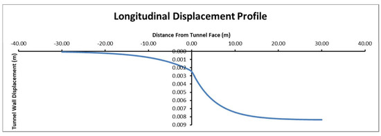
Figure 6.
Longitudinal displacement profile.
Tunnel excavation deformations affect the ground around it up to a distance of 1.5 times the tunnel diameter. After this point, the displacements caused by the excavation are assumed to be stable [27].
The equations used to calculate the pressures of the tunnel support systems are given in Table 4. These equations were proposed by Hoek and Brown [26] and Brady and Brown [57] for shotcrete/concrete and bolt and circular steel supports. It is assumed that the steel shoring is applied in a circularly closed section, the bolts are applied along the tunnel perimeter in a regular pattern, and the shotcrete or concrete is applied as a full section ring [11].
Table 4.
Support capacity equations [26,57].
The Cukurcayir 1 tunnel was designed using the NATM [58,59,60]. The tunnel excavation was divided into top heading, bench, and invert stages. A rigid support system was chosen due to the low overburden height and the weak soil conditions. In addition, the presence of buildings and highway on the surface was another critical factor for choosing the rigid support system. Details of the support system that is used in the Cukurcayir 1 tunnel are presented in Table 5 and Figure 7 and Figure 8. The support system was designed to be an 88.9 mm thick umbrella and the tunnel face is bolted to prevent possible slips and collapse in the tunnel face. In addition, the bolts installed in the bench sections were designed with completely dry drilling and 8 m of PG bolts were applied. A 40 cm layer of shotcrete (C25/30) and HEB200 steel rib were used in the tunnel [44]. In addition, a temporary invert was applied in the top heading to prevent deformations.
Table 5.
Tunnel support details.
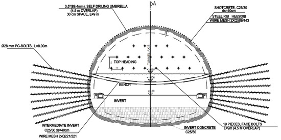
Figure 7.
Tunnel cross section support details. Reprinted with permission from Ref. [44]. 2025, General Directorate of Highways.
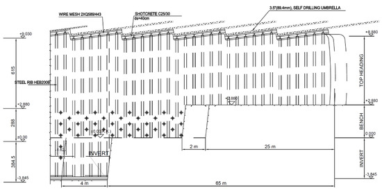
Figure 8.
Tunnel support details longitudinal profile. Reprinted with permission from Ref. [44]. 2025, General Directorate of Highways.
The determined tunnel support system pressures are given in Table 6. The longitudinal displacement profile (Figure 9), ground reaction curve and plastic zone radius plot (Figure 10), and support reaction curve (Figure 11) are given as well.
Table 6.
Support pressure between entrance portal and Km:210 + 150.
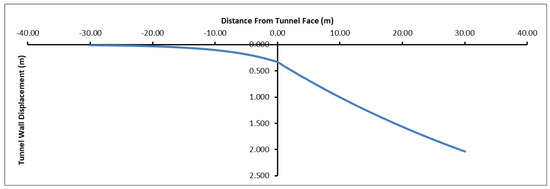
Figure 9.
Longitudinal displacement profile for gravel sandy unit.
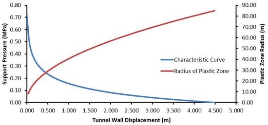
Figure 10.
Ground reaction curve for gravel sandy clay unit.
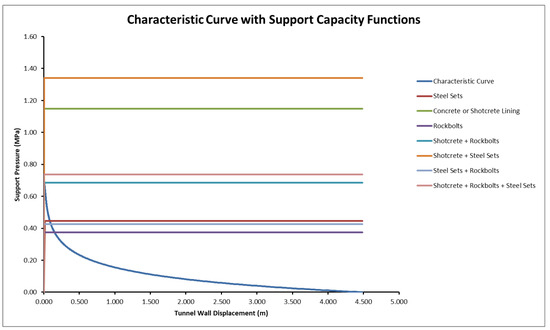
Figure 11.
Characteristic curve with support capacity functions for support system elements.
When the longitudinal displacement profile was examined, deformations of 33.4 and 40 cm were observed at the tunnel face and in a 1.0 m section at the back of the tunnel face, respectively. These values continued to increase along the tunnel and reached up to 2.042 m at 30 m behind the tunnel due to the very weak ground conditions (Figure 9). This result demonstrates that the tunnel should always be supported to maintain the stability of the tunnel face and roof.
The ground reaction curve shows that the displacements developed very rapidly in the tunnel. The deformations occurring at the point where the critical pressure was 0.57 MPa was calculated to be 3.4 cm, whereas the radius of the plastic zone was 8.5 m (Figure 10). In the unsupported condition, the plastic zone developed to cover the entire overburden thickness.
On the other hand, in the support reaction curves for the tunnel with the specified support systems (Figure 11), it can be seen that no stability problem occurred in the tunnel if the support systems did not allow deformations in the tunnel.
In the calculations, the critical pressure (Pcr) was 0.57 MPa, the elastic deformation (uie) was 0.16 m, the radius of the plastic zone (rp) was 88 m, the plastic deformation (uip) was 4.48 m, and the deformation of the tunnel face (uif) was 0.33 m (Table 7).
Table 7.
Analysis of tunnel behavior for gravel–sandy–clay and metasiltstone units.
4. Three-Dimensional (3D) Numerical Analysis
Recently, 3D numerical analyses have been used extensively for simulation of tunnel excavations. Zhang et al. [61] provided a detailed comparison with evaluation of three design alternatives through 3D numerical analyses on the stress distribution inside the advance core, ground deformation, and soil arching over the tunnel crown, and they [61] stated that the numerical results agreed well with the field monitoring data. Falcone et al. [62] considered 3D modelling of construction sequences and subsoil heterogeneity effects on the seismic response of shallow tunnels in complex topographical settings, and the results of the numerical investigations performed by Falcone et al. [62] highlighted a clear correlation of the tunnel lining force distribution with the overburden thickness variation along the longitudinal direction of the tunnel. Jafari et al. [63] proposed a failure mechanism for evaluating active tunnel face failure, using the upper-bound theorem of limit analysis and they [63] used 3D numerical analyses during the validation stage of the proposed approach. A FLAC3D-based numerical study was performed by Li et al. [64] for spatiotemporal stability responses of tunnel excavation under cyclical footage impact while Saif et al. [65] employed 3D parametric analyses of cross-passages in shallow tunnels within noncohesive soils. Habib and El-Khouly [66] examined the behavior of a tunnel face reinforced by longitudinal pipes, using a 3D finite element model.
In order to investigate the interaction between the ground and support system in the tunnel, 3D numerical analyses were performed using the Flac3d software [67]. The Flac3d program was developed by Itasca and uses the finite difference method. Field conditions and tunnel support systems can be input into the model and tunnel excavation stages can be introduced in stages as top heading, bench, and invert. The tunnels were modeled as double tubes and the overburden thickness was assumed to be 40 m. In the model, the length was 100 m in the Y direction, 215 m in the X direction, and 120 m in the Y direction (Figure 12). The Mohr–Coulomb failure criterion was used in the model, which was solved using the gravity method. The model was divided into top heading, bench, and invert stages. The excavation process was carried out primarily in the left tunnel, and then the excavations continued for the right tunnel. In order to provide the necessary advance distances in the left tunnel, it was assumed that the first 60 m of excavation at the top heading, up to 40 m at the bench, and 36 m at the invert section were excavated. After this stage, the displacements were reset and then the excavation process continued through the top heading, bench, and invert stages. The tunnel was excavated between 60 m and 66 m at the top heading, 40 and 48 m in the bench section, and between 36 and 44 m in the invert section. After the excavation of the left tunnel was completed, the excavation of the first 10 m section of the right tunnel was conducted, and then the excavation progress continued in the bench and invert sections (Figure 13 and Figure 14). The excavation stages are given in Table 8. In order to observe the displacements in the tunnels, measuring points were arranged around the tunnel. The changes in these points were obtained graphically depending on the number of steps.
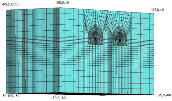
Figure 12.
Three-dimensional model conditions.
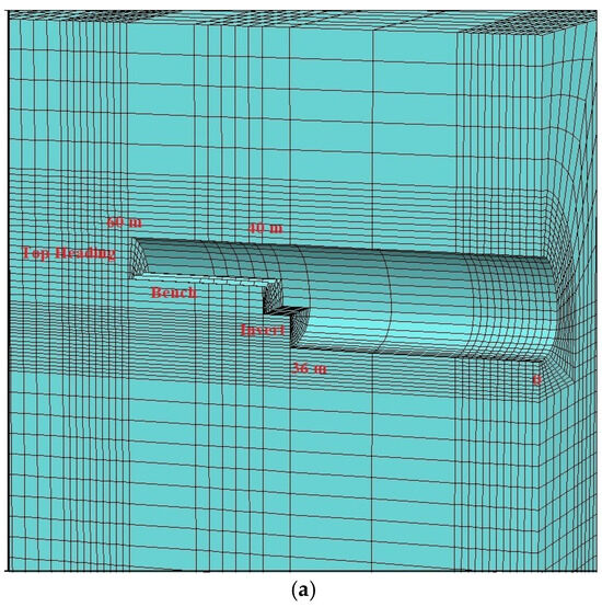
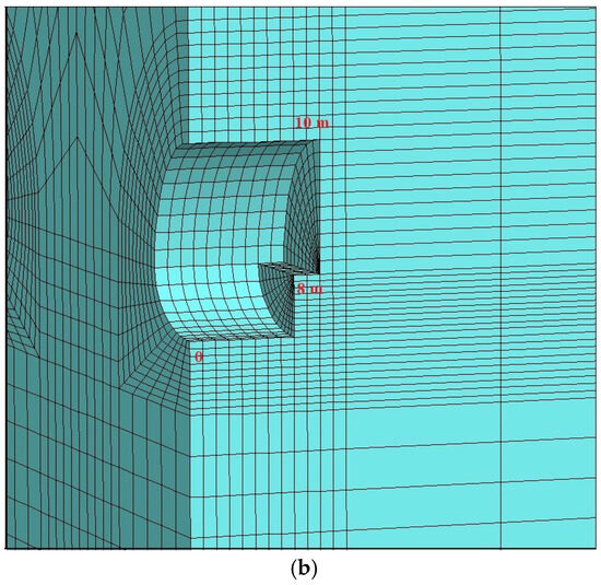
Figure 13.
Excavation sequence: (a) left tunnel; (b) right tunnel.
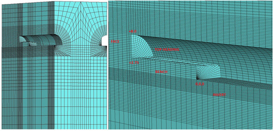
Figure 14.
Top heading, bench, and invert excavation sequence.
Table 8.
Modeling stages.
The numerical model was calibrated by comparing the predicted tunnel convergence and ground surface subsidence with measured field data. Initial estimates of the elastic modulus (E) were obtained from empirical correlations with SPT-N values [45,68] and the plasticity index of soils. Poisson’s ratio (ν) values were selected from within the typical range for cohesive soils (0.30–0.38) [69]. These parameters were iteratively adjusted until the numerical results reproduced the observed deformation magnitudes with an accuracy of ±10%. This procedure ensured that the adopted stiffness parameters represented realistic ground response properties for the Cukurcayir 1 tunnel alignment.
Shotcrete was defined as a shell element, face bolts were defined as cable bolts and the umbrellas were defined as pile elements. The shotcrete, bolt, and umbrella properties are given in Table 9, Table 10 and Table 11.
Table 9.
Parameters used for shotcrete and interior lining concrete.
Table 10.
Parameters used for cable bolts.
Table 11.
Parameters used for umbrellas.
The support elements used in the model are presented in Figure 15.
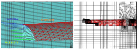
Figure 15.
Support elements in tunnel.
The measurement points along the tunnel for measuring the displacements are shown in Figure 16.
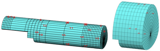
Figure 16.
Displacement measurement points in the tunnel.
The Flac3d program uses the bulk and shear moduli in its analyses. Equations (18) and (19) were used to calculate the bulk and shear moduli. The calculated values are given in Table 12.
Table 12.
Bulk, shear, and deformation modulus parameters.
Bulk Modulus
Shear Modulus
Evaluation of the Numerical Analysis Results
In order to evaluate the numerical analysis results, the displacements in the tunnel at the pre-defined points were examined. The deformation in the roof section of the left tunnel at 60 m was 3.86 cm at maximum, 4.11 cm at 62 m, and 3.56 cm at 64 m (Figure 15). When the deformation trend was examined at 60 m, a deformation of approximately 1.0 cm occurred after the first excavation, while the deformations at 60 m increased by 0.6 cm to 1.6 cm when the excavation reached between 61 and 62 m. The deformations remained stable at 60 m when the bench excavations were carried out between 40 and 44 m. Thus, the distance between the top heading and the bench appears to be sufficient. When re-excavating between 62 and 63 m in the top heading, the deformations increased by 1 cm and reached up to 2.7 cm. After this stage, the bench was excavated between 44 and 46 m and the deformations continued until 60 m. In the upper half, while the excavations continued between 64 m and 65 m and between 65 m and 66 m, the deformations increased by 1 cm at 60 m in each 1 m of excavation, and the deformations at 66 m increased to 3.6 cm. At the point where the invert excavation started (between 40 and 44 m), the deformations increased by 0.2 cm and stabilized at 3.86 cm (Figure 17). After this stage, excavation was started in the right tunnel and no impact was observed on the left tunnel. Thus, at this point, the stability of the tunnel had been ensured and the inner lining concrete can be installed. The changes at 60 m were similar to those observed at 62 m and 64 m (Figure 17).
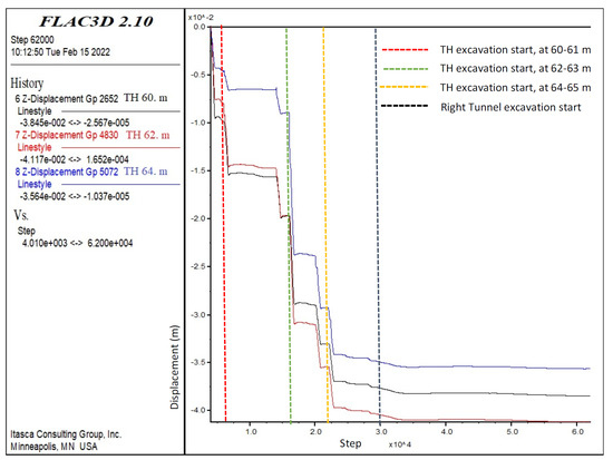
Figure 17.
Left tunnel top heading displacements in Z-direction at 60, 62, and 64 m.
When the displacements occurring during the bench excavations were examined (Figure 18), the horizontal displacements were found to be below 1 cm. The horizontal displacements at 2, 10, 12, 24, and 42 m were used in the analysis of the deformations. At this location, an increase in horizontal displacements was only observed at 42 m, which is close to the tunnel excavation face, while it was fixed below 0.1 cm at the other points. Changes in the points close to the tunnel entrance (2, 10, 12, and 24 m) were observed until the top heading was excavated up to 62 m, and then they became fixed. Thus, the excavation of the right tunnel seemed to have no effect on the left tunnel in the first 10 m. At 42 m, while the deformations increased during the top heading, bench and invert excavations, all the deformations remained below 1 cm. No major impact was observed. The changes at 42 m increased up to 0.4 cm when the top heading was excavated between 60–61 m and 61–62 m. Afterwards, it remained stable, and the horizontal displacements increased to 0.65 cm at the point where the bench excavations started (between 42 and 44 m), and the bench deformations remained stable during the top heading excavations between 64–65 m and 65–66 m. Therefore, the results indicate that the distance between the top heading and bench is sufficient.
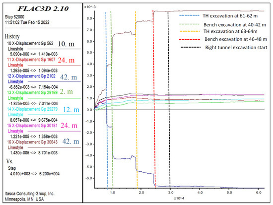
Figure 18.
Bench displacements in X-direction at 2, 10, 12, 24, and 42 m.
The displacements in the invert section are given in Figure 19. Next, the displacements in the invert section at 12, 24, and 42 m were investigated. The maximum displacements of 3.4 cm in the invert section occurred at 42 m. The displacements at 42 m showed an increase of 4 mm during top heading excavation between 60–61 m and 61–62 m, indicating that the top heading excavations did not have a large effect on these displacements. However, after the start of the bench excavations (between 40–42 m and 42–44 m), an increase in deformations of up to 3 cm was observed. When the top heading excavations started again (between 62–63 m and 63–64 m), no significant increase was observed. At the point when the excavation of the lower half started again, the displacement increased again but was at the 0.2 cm level. In the next stage, the 40–44 m excavation of the invert section showed the same displacements as those after the construction was completed. At this stage, stability is ensured at the invert due to the pouring of invert concrete immediately after excavation. The displacements at 12 and 24 m of the tunnel remained at the 1 mm level and continued to be stabilized.
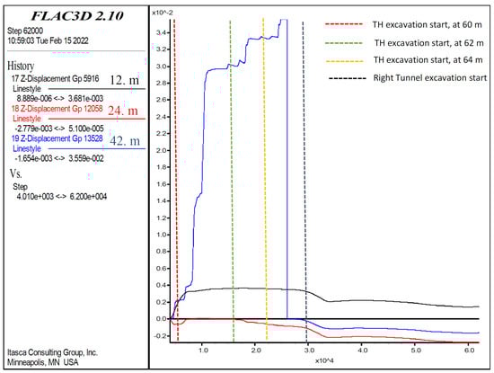
Figure 19.
Left tunnel invert section displacements in Z-direction at 12, 24, and 42 m.
At the top heading of the right tunnel (Figure 20), deformations occurred at the 7.3 cm level. In the first stage, excavation was carried out in the 10 m section in the top heading and then the lower half, and finally, the invert excavations were carried out. The deformations continued to increase after each stage of excavation of the top heading. While the deformations increased by 0.5 cm in the first 5 m section, the deformation increased to 1.0 cm at each level of the excavations after 5 m. This situation reveals that in the case of progressing without ring closing in the upper half section, the increase in deformation increases. Bench and invert excavations of the tunnel should be carried out sequentially. It was observed that the deformations in the bench and invert excavations remained constant in the top heading.
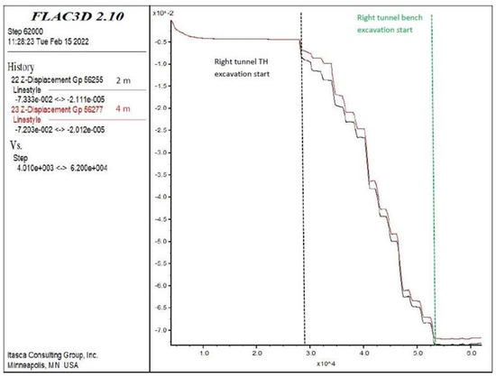
Figure 20.
Right tunnel vertical displacements (Z-direction) in top heading at 2 and 4 m.
The deformations that occurred at 2 and 4 m in the bench were examined (Figure 21). The deformations occurring in the bench continued to increase by 0.5 cm during the excavations of the top heading, whereas the deformation in the bench increased to 3.0 cm after the completion of the first 6 m of excavation in the bench. After the invert excavations, the deformations in the bench became stable.
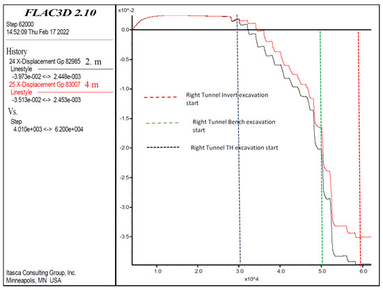
Figure 21.
Right tunnel horizontal displacements (X-direction) in the bench at 2 and 4 m.
On the other hand, the deformations at the invert region of the right tunnel increased the deformations in the tunnel roof after the excavation in the top heading (Figure 22). Deformations in the form of swelling occurred at the base section and deformations of up to 18 cm occurred. During the first 10 m of excavation in the top heading, an average of 1.0 cm of swelling occurred at each level, and an increase of 1.5 cm was observed in the bench of the excavation. After the invert excavations, the deformations were fixed by defining the invert concrete in the model. The most important result was that invert excavations should be carried out in shortest time interval possible in tunnels excavated on weak soils in order to ensure stability.
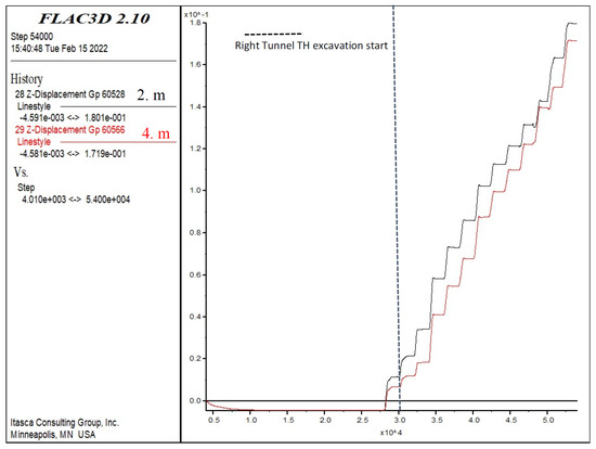
Figure 22.
Right tunnel vertical displacements (Z-direction) in the invert at 2 and 4 m.
The progressive development and stabilization of displacements that were observed in the numerical analyses can also be interpreted within a granular-creep and particle-packing framework. In weakly cemented or partially saturated clayey–sandy materials, the time-dependent response was not solely governed by macroscopic stress redistribution but also by the micro-mechanical rearrangement of particles and contact evolution under sustained loading. The gradual reduction in deformation rate observed during the excavation and support installation stages can therefore be attributed to an increase in packing density and the progressive mobilization of inter-particle friction. Similar findings were reported by Tong et al. [70,71], who demonstrated that particle shape and packing fraction significantly influence the creep and fluidity of granular materials. This interpretation provides a micro-mechanical rationale for the delayed deformation stabilization trends observed in both the numerical analysis and field monitoring results.
5. Comparison of Measured Deformations and Analysis Results
One of the most important issues to be considered in tunnel excavation in weak clay and sandy units is keeping water away from the tunnel. In such soils, when clayey and sandy units interact, excess water adds an additional load depending on the swelling feature of the soil, and it triggers slippage by decreasing the cohesion due to undrained conditions. For this reason, one of the most important steps during the construction phase is installing bolts and umbrellas in a dry environment. All the boreholes in Cukurcayir 1 tunnel were dry-drilled and contact with water was prevented. As can be seen from Figure 23, the tunnel face remained stable immediately after the excavation.
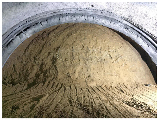
Figure 23.
Tunnel excavation face.
In order to observe the tunnel stability, deformation measurements were carried out continuously. The deformation measurement points are shown in Figure 24. The measurement results are presented in Figure 25 and Figure 26.
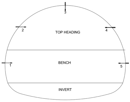
Figure 24.
Deformation measurement points.
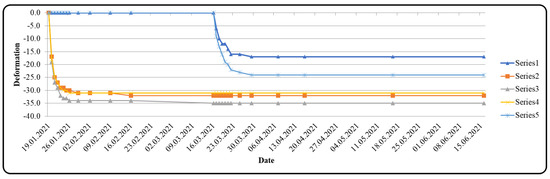
Figure 25.
Vertical displacement at Km:11 + 677 (deformation unit is mm).
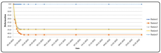
Figure 26.
Vertical displacement at Km:11 + 864 (deformation unit is mm).
The maximum deformations were 4.2 cm at Km:11 + 864 and 3 cm at Km:11 + 796. Compared to the deformations on the left tunnel roof given in Figure 22, the measurements were at the 4.0 cm level. These measured values are in agreement with those from the numerical analysis.
In the numerical analysis results for the right tunnel (Figure 20, Figure 21 and Figure 22), the deformations continued to increase in every round if only the 10 m interval advance was carried out in the top heading without bench or invert excavation.
No stability problems were encountered in the tunnel when the tunnel excavation and support system installation were performed sequentially. In other words, if the top heading, bench, and invert excavations are carried out consecutively, the deformations remain stable.
6. Conclusions
In this study, the Cukurcayir 1 tunnel, which was excavated in weak ground units under a shallow overburden close to a residential area, was studied using 3D numerical analyses and the results were compared with the deformations measured during the excavations. As stated by Namlı [72], ground surfaces settlementis the most significant restriction when constructing shallow metro station tunnels in urban areas. This statement is valid for each shallow underground opening excavated in urban areas. Due to the tunnel’s location, it was excavated using a rigid support system that does not allow for deformation. Collapses and excessive deformations were prevented due to the implementation of an umbrella system in order to support the tunnel roof. The conclusions of this study are as follows:
- (a)
- The results of numerical analyses and the deformation measurements performed in the tunnel were similar. Due to the closeness of the tunnel to a residential area, the internal tunnel deformations were limited and the deformations were stabilized at the 4 cm level.
- (b)
- One of the most important factors when excavating tunnels in weak ground is tunnel roof and face stability. The design of the Cukurcayir 1 tunnel ensured this stability.
- (c)
- Tunnel top heading, bench, and invert excavation phases should be kept as short as possible, and the ring should be closed immediately. In weak ground excavations, the distance between the top heading and bench should be a maximum of 20–25 m. During the analyses and excavation stages, this behavior was clearly observed.
- (d)
- During tunnel excavations, squeezing should be expected in the tunnel invert during the excavation process in the top heading. In these cases, the tunnel invert should be immediately excavated and the ring should be closed with invert concrete.
- (e)
- In tunnels excavated as double tubes, the distance between the excavation face of the tunnels is critical. For the tunnels to not affect each other, a distance of at least 4 times the tunnel diameter should be left between the tunnel excavation faces. During the excavations of the Cukurcayir 1 tunnel, this principle was adhered to and successful results were achieved.
- (f)
- The creation of arching around the tunnel by allowing deformation in weak ground often causes a very rapid increase in deformations. In this case, it caused failures in the tunnel. Therefore, support systems should be sized by prioritizing the prevention of excess deformation on weak ground.
- (g)
- It is worth noting that the FLAC3d analyses presented in this study included several simplifications. Groundwater level changes were represented using steady-state pore pressure conditions rather than transient flow conditions. Time-dependent soil behaviors, such as consolidation and creep, were not explicitly modeled and were analyzed qualitatively based on previous studies. Furthermore, the tunnel lining was assumed to exhibit linear elastic behavior. While these assumptions are limited in scope, they were considered acceptable for comparing deformation mechanisms and support performance.
- (h)
- The tunnel roof must be stabilized with a long umbrella. Otherwise, possible roof slips could cause failures, leading to collapse. Deformations should not be allowed, especially in shallow tunnels excavated in a residential area. A collapse in the tunnel is likely to reflect up to the surface and cause damage.
- (i)
- Future research can enhance the predictive and interpretive capabilities of such analyses by integrating multimodal and coupled hydromechanical frameworks. Recent advances, such as multi-channel fusion prediction of TBM thrust based on multimodal decomposition and reconstruction [73] and analytical modeling of nonlinear seismic metasurfaces of saturated porous media [74], offer complementary perspectives for linking numerical simulations, in situ monitoring, and fluid–solid interactions. Integrating these data-driven analytical approaches with numerical modeling could significantly improve the reliability of tunnel deformation predictions and improve performance under complex ground conditions. It will be useful to consider the following points in future studies. In particular, further studies of twin-tube tunnels and the detailed studies of their interaction conditions are crucial. Determination of the effects of top heading, bench and invert distances on tunnel deformations is important and necessary revisions should be performed. In addition, the optimum ring closure distance should be determined. As the most important recommendation, the additional supports that can be applied in addition to the temporary invert to prevent vertical and horizontal deformations in the upper half should be re-investigated.
Author Contributions
Conceptualization, R.T. and C.G.; methodology, R.T. and E.B.A.; software, R.T.; validation, R.T., E.B.A. and C.G.; formal analysis, R.T.; investigation, R.T. and E.B.A.; resources, R.T. and C.G.; data curation, R.T.; writing—original draft preparation, R.T. and E.B.A.; writing—review and editing, C.G.; visualization, R.T. and E.B.A.; supervision, E.B.A. and C.G.; project administration, C.G. All authors have read and agreed to the published version of the manuscript.
Funding
This research received no external funding.
Data Availability Statement
The whole data used in the study is given in the manuscript.
Acknowledgments
This study is part of the PhD thesis of the first author, RT, and the other authors, EBA and CG, are the supervisors of the thesis. The authors thank the General Directorate of Highways of Türkiye for providing permission to use their data.
Conflicts of Interest
Author Ebu Bekir Aygar was employed by the company IG Tunnel Engineering Consulting Company. The remaining authors declare that the research was conducted in the absence of any commercial or financial relationships that could be construed as a potential conflict of interest.
References
- Jin, D.; Yuan, D.; Li, X.; Zheng, H. Analysis of the settlement of an existing tunnel induced by shield tunneling underneath. Tunn. Undergr. Space Technol. 2018, 81, 209–220. [Google Scholar] [CrossRef]
- Tan, J.; Cui, Z.; Yuan, L. Study on the Long-term Settlement of Subway Tunnel in Soft Soil Area. Mar. Georesources Geotechnol. 2016, 34, 486–492. [Google Scholar] [CrossRef]
- Maras-Dragojevic, S. Analysis of ground settlement caused by tunnel construction. Gradevinar 2012, 64, 573–581. [Google Scholar] [CrossRef]
- Suliman, L.; Liu, X.; Yanyang, S.; Zhou, Z.; Hai, C.; Abdalmageed, A. Settlement Characteristics due to the Excavation of Multiple Parallel Tunnels at Small Distances. Transp. Infrastruct. Geotech. 2025, 12, 204. [Google Scholar] [CrossRef]
- Lai, H.; Zhao, X.; Kang, Z.; Chen, R. A new method for predicting ground settlement caused by twin-tunneling under-crossing an existing tunnel. Environ. Earth Sci. 2017, 76, 726. [Google Scholar] [CrossRef]
- Meng, F.; Chen, R.; Kang, X. Effects of tunneling-induced soil disturbance on the post-construction settlement in structured soft soils. Tunn. Undergr. Space Technol. 2018, 80, 53–63. [Google Scholar] [CrossRef]
- Republic of Türkiye; Ministry of Transport and Infrastructure; General Directorate of Highways; Department of Research & Development. Highway Technical Specifications; Republic of Türkiye, Ministry of Transport and Infrastructure, General Directorate of Highways, Department of Research & Development: Ankara, Türkiye, 2023. [Google Scholar]
- Aksoy, C.O.; Uyar, G.G.; Posluk, E.; Ogul, K.; Topal, I.; Kucuk, K. Non-deformable support system application at tunnel-34 of Ankara-İstanbul high speed railway project. Struct. Eng. Mech. 2016, 58, 869–886. [Google Scholar] [CrossRef]
- Schubert, W. Dealing with squeezing conditions in alpine tunnels. Rock Mech. Rock Engng. 1996, 29, 145–153. [Google Scholar] [CrossRef]
- Aygar, E.B. A Critical Approach to the New Austrian Tunneling Method in Bolu Tunnels. Master’s Dissertation, Hacettepe University, Ankara, Turkey, 2000. [Google Scholar]
- Hoek, E. Practical Rock Engineering. 2007. Available online: https://www.rocscience.com/assets/resources/learning/hoek/Practical-Rock-Engineering-Full-Text.pdf (accessed on 31 October 2025).
- Sharifzadeh, M.; Daraei, R.; Broojerdi, R.M. Design of sequential excavation tunneling in weak rocks through findings obtained from displacements based back analysis. Tunn. Undergr. Space Technol. 2012, 28, 10–17. [Google Scholar] [CrossRef]
- Klopcic, J.; Logar, J.; Ambrozic, T.; Stimulak, A.; Marjetic, A.; Bogatin, S.; Majes, B. Displacements in the exploratory tunnel ahead of the excavation face of Sentvid Tunnel. Acta Geotech. Slov. 2006, 3, 17–33. [Google Scholar]
- Ozsan, A.; Başarır, H. Support capacity estimation of a diversion tunnel in weak rock. Eng. Geol. 2003, 68, 319–331. [Google Scholar] [CrossRef]
- Do, N.A.; Dias, D.; Oreste, P.; Maigre, I.D. 2D tunnel numerical investigation: The influence of the simplified excavation method on tunnel behaviour. Geotech. Geol. Eng. 2014, 32, 43–58. [Google Scholar] [CrossRef]
- Han, U.C.; Kim, I.C.; Hong, G.U.; Kang, I.Y. Construction of twin tunnel in weak and blocky rock mass by using arch supporting method. IOP Conf. Ser. Earth Environ. Sci. 2021, 861, 052112. [Google Scholar] [CrossRef]
- Marinos, V. Tunnel behaviour and support associated with the weak rock masses of flysch. J. Rock Mech. Geotech. Eng. 2014, 6, 227–239. [Google Scholar] [CrossRef]
- Vlachopoulos, N.; Vazaios, I.; Madjdabadi, B.M. Investigation into the influence of excavation of twin-bored tunnels within weak rock masses adjacent to slopes. Can. Geotech. J. 2018, 55, 1533–1551. [Google Scholar] [CrossRef]
- Aygar, E.B. Investigation of the Bolu Tunnel Stability by Means of Static and Dynamic Analyses. Ph.D. Dissertation, Hacettepe University, Ankara, Turkey, 2007. [Google Scholar]
- Aygar, E.B. Evaluation of New Austrian Tunnelling Method applied to Bolu tunnel’s weak rocks. J. Rock Mech. Geotech. Eng. 2020, 12, 1166. [Google Scholar] [CrossRef]
- Aygar, E.B.; Gokceoglu, C. Problems encountered during a railway tunnel excavation in squeezing and swelling materials and possible engineering measures: A case study from turkey. Sustainability 2020, 12, 1166. [Google Scholar] [CrossRef]
- Aygar, E.B.; Gokceoglu, C. A special support design for a large-span tunnel crossing an active fault (t9 tunnel, Ankara–Sivas high-speed railway project, turkey). Environ. Earth Sci. 2021, 80, 37. [Google Scholar] [CrossRef]
- Aygar, E.B.; Gokceoglu, C. Analytical solutions and 3d numerical analyses of a shallow tunnel excavated in weak ground: A case from Turkey. Int. J. Geo-Eng. 2021, 12, 9. [Google Scholar] [CrossRef]
- Karahan, S.; Posluk, E.; Büyükdemirci, F.B.; Gokceoglu, C. Re-design of a railway tunnel intersected by surface rupture of the Erkenek fault segment during the 6 February 2023 Pazarcik (Mw 7.7) Earthquake (Türkiye). Bull. Eng. Geol. Environ. 2025, 84, 198. [Google Scholar] [CrossRef]
- Posluk, E.; Karahan, S.; Dalğıç, S.; Gokceoglu, C. An Empirical Equation for Tunnel Squeezing Prediction in Weak Rock Masses. Adv. Civ. Eng. 2025, 2025, 7026847. [Google Scholar] [CrossRef]
- Hoek, E.; Brown, E.T. Underground Excavations in Rock; Institution of Mining and Metallurgy: London, UK, 1980. [Google Scholar]
- Hoek, E. Rock Support Interaction Analysis for Tunnels in Weak Rock Masses. Available online: https://static.rocscience.cloud/assets/verification-and-theory/RocSupport/Rock-support-interaction-analysis-for-tunnels-2-April-2012.pdf (accessed on 1 November 2025).
- Hoek, E.; Kaiser, P.K.; Bawden, W.F. Support of Underground Excavations in Hard Rock; Balkema: Rotterdam, The Netherlands, 2000. [Google Scholar]
- Dong, C.; Lin, J.; Cao, G.; Cheng, H.; Shi, L.; Zhang, X. Analytical Study on Surface Settlement Troughs Induced by the Sequential Excavation of Adjacent and Parallel Tunnels in Layered Soils. Adv. Civ. Eng. 2022, 2022, 2489711. [Google Scholar] [CrossRef]
- Huang, K.; Sun, Y.; Huang, X.; Li, Y.; Jiang, M.; Liu, R. Effects of Different Construction Sequences on Ground Surface Settlement and Displacement of Single Long Pile due to Twin Paralleled Shield Tunneling. Adv. Civ. Eng. 2021, 2021, 5559233. [Google Scholar] [CrossRef]
- Kumar, J.; Jain, H. Elasto-plastic ground settlement response and stability of single and twin circular unsupported and supported tunnels. Transp. Geotech. 2021, 30, 100620. [Google Scholar] [CrossRef]
- Zhang, Q.; Zhang, X.-P.; Wang, H.-J.; Zhang, X.-Y.; Li, F.-Y.; Xu, D. Ground deformation induced by a shallow-buried twin-tunnel with small spacing: A case study of Guangzhou Metro Line 18 excavated by earth-pressure balance TBM. Environ. Earth Sci. 2023, 82, 297. [Google Scholar] [CrossRef]
- Jamshasb, F.; Shahrbabaki, M.K. The Impact of Approach in Shallow Twin Tunnels on the Convergence. Procedia Earth Planet. Sci. 2015, 15, 325–329. [Google Scholar] [CrossRef][Green Version]
- Guo, H.; Yuan, D.; Jin, D.; Ma, Q.; Zhao, H. Theoretical Analysis and Numerical Simulations for the Safe Clear Distance of a Shallow-Buried Twin-Shield Tunnel with Small Spacing. KSCE J. Civ. Eng. 2024, 28, 5277–5289. [Google Scholar] [CrossRef]
- Li, C.; Zheng, H.; Hu, Z.; Liu, X.; Huang, Z. Analysis of Loose Surrounding Rock Deformation and Slope Stability at Shallow Double-Track Tunnel Portal: A Case Study. Appl. Sci. 2023, 13, 5024. [Google Scholar] [CrossRef]
- Mirsepahi, M.; Nayeri, A.; Lajevardi, S.H.; Mirhosseini, S.M. Performance of Side-by-Side Twin Tunnel Excavation Under a Single Pile and Pile Group by the NATM. Soil Mech. Found. Eng. 2023, 59, 537–543. [Google Scholar] [CrossRef]
- Yu Huat, C.; Armaghani, D.J.; Lai, S.H.; Rasekh, H.; He, X. Simulation of Surface Settlement Induced by Parallel Mechanised Tunnelling. Sustainability 2023, 15, 13265. [Google Scholar] [CrossRef]
- Chen, Y.; Yang, B. A Parametric Study to Assess the Effects of Twin-Tunnel Excavation on Bridge Pile Groups. Indian Geotech. J. 2025, 1–17. [Google Scholar] [CrossRef]
- Islam, M.S.; Iskander, M. Three-dimensional numerical investigation of ground settlement caused by side-by-side twin tunnels. Tunn. Undergr. Space Technol. 2025, 159, 106509. [Google Scholar] [CrossRef]
- Quevedo, F.P.M.; Colombo, C.A.M.M.; Bernaud, D.; Maghous, S. 3D Finite Element Analysis of Rock Deformation in Twin Circular Tunnels with a Transverse Gallery Using Plasticity and Time-Dependent Models. Geotech. Geol. Eng. 2025, 43, 149. [Google Scholar] [CrossRef]
- Do, N.A.; Dias, D.; Golpasand, M.R.B.; Dang, V.K.; Nait-Rabah, Q.; Pham, V.V.; Dang, T.T. Numerical analyses of twin stacked mechanized tunnels in soft grounds—Influence of their position and construction procedure. Tunn. Undergr. Space Technol. 2022, 130, 104734. [Google Scholar] [CrossRef]
- Wang, J.; Cao, A.; Wu, Z.; Sun, Z.; Lin, X.; Sun, L.; Liu, X.; Li, H.; Sun, Y. Numerical Simulation of Ultra-Shallow Buried Large-Span Double-Arch Tunnel Excavated under an Expressway. Appl. Sci. 2022, 12, 39. [Google Scholar] [CrossRef]
- Republic of Türkiye; Ministry of Transport and Infrastructure; General Directorate of Highways; Department of Research & Development. Cukurcayir 1 Tunnel Projects Report; Republic of Türkiye, Ministry of Transport and Infrastructure, General Directorate of Highways, Department of Research & Development: Ankara, Türkiye, 2022. [Google Scholar]
- Republic of Türkiye; Ministry of Transport and Infrastructure; General Directorate of Highways; Department of Research & Development. Cukurcayir 1 Tunnel Geological and Geotechnical Report; Republic of Türkiye, Ministry of Transport and Infrastructure, General Directorate of Highways, Department of Research & Development: Ankara, Türkiye, 2022. [Google Scholar]
- Stroud, M.A.; Butler, F.G. The Standard penetration test and the engineering properties of glacial materials. In Proceedings of the Symposium On the Engineering Behaviour of Glacial Materials, Birmingham, UK, 21–23 April 1975; pp. 124–135. [Google Scholar]
- Terzaghi, K.; Peck, R.B.; Mesri, G. Soil Mechanics in Engineering Practice, 3rd ed.; John Wiley and Sons, Inc.: New York, NY, USA, 1996. [Google Scholar]
- Jethwa, J.L.; Singh, B.; Singh, B. Estimation of ultimate rock pressure for tunnelings under squeezing rock conditions. In Proceedings of the ISRM Symposium Design and Performance of Underground Excavation, Cambridge, UK, 3–6 September 1984. [Google Scholar]
- Hoek, E.; Marinos, P. Predicting tunnel squeezing problems in weak heterogeneous rock masses. Tunn. Tunn. Int. 2000, 32, 45–51. [Google Scholar]
- Anagnostou, G.; Kovári, K. Face stability conditions with earth pressure balance shields. Tunn. Undergr. Space Technol. 1996, 11, 165–173. [Google Scholar] [CrossRef]
- Mair, R.J.; Hight, D.W. Compensation grouting. In World Tunnelling and Subsurface Excavation; The Minning Journal: London, UK, 1994; pp. 361–367. [Google Scholar]
- Panet, M.; Guenot, A. Analysis of Convergence Behind the Face of a Tunnel. In Proceedings of the 3rd International Symposium, Tunnelling 82, London, UK, 7–11 June 1982; IMM: Catania, Italy, 1982; pp. 197–204. [Google Scholar]
- Panet, M. Le calcul des tunnels par la methode convergence-confinement. In Presses de l’ecole Nationale de Ponts et Chausse’s; Presses des Ponts: Paris, France, 1995; Available online: https://hal.science/hal-04181778/ (accessed on 1 November 2025).
- Unlu, T.; Gercek, H. Effect of Poisson’s ratio on the normalized radial displacements occurring around the face of a circular tunnel. Tunneling Undergr. Space Technol. 2003, 18, 547–553. [Google Scholar] [CrossRef]
- Carranza-Torres, C.; Fairhurst, C. Application of convergence-confinement method of tunnel design to rock masses, that satisfy the Hoek–Brown failure criterion. Tunneling Undergr. Space Technol. 2000, 15, 187–213. [Google Scholar] [CrossRef]
- Vlachopoulos, N.; Diederichs, M. Improved longitudinal displacement profiles for convergence-confinement analysis of deep tunnels. Rock Mech. Rock Eng. 2009, 42, 131–146. [Google Scholar] [CrossRef]
- Oke, J.; Vlachopoulos, N.; Diederichs, M.S. Improvement to the convergence-confinement method: Inclusion of support installation proximity and stiffness. Rock Mech. Rock Eng. 2018, 51, 1495–1519. [Google Scholar] [CrossRef]
- Brady, B.H.G.; Brown, E.T. Rock Mechanics for Underground Mining; Allen and Unwin: London, UK, 1985. [Google Scholar]
- Rabcewicz, L. The New Austrian Tunnelling Method. Part One. Water Power 1964, 453–457. [Google Scholar]
- Rabcewicz, L. The New Austrian Tunnelling Method, Part Two. Water Power 1964, 511–515. [Google Scholar]
- Rabcewicz, L. The New Austrian Tunnelling Method, Part Three. Water Power 1965, 19–24. [Google Scholar]
- Zhang, Z.; Li, L.; Wang, S.; Huang, X. A comparative numerical analysis of design variation plans for a shallow tunnel in very soft ground after a sudden accident. Eng. Fail. Anal. 2022, 141, 106674. [Google Scholar] [CrossRef]
- Falcone, G.; di Lernia, A.; Elia, G. 3D modelling of construction sequences and subsoil heterogeneity effects on the seismic response of shallow tunnels in complex topographical settings. Comput. Geotech. 2025, 180, 107077. [Google Scholar] [CrossRef]
- Jafari, P.; Rasekh, E.; Asheghi Mehmandari, T.; Mohammadifar, M.; Fahimifar, A.; Armaghani, D.J. Upper-Bound Solutions for Active Face Failure in Shallow Rectangular Tunnels in Anisotropic and Non-homogeneous Undrained Clays. Geotech. Geol. Eng. 2025, 43, 129. [Google Scholar] [CrossRef]
- Li, S.; Dai, B.; Hou, Y.; Li, D. Spatiotemporal Stability Responses of Tunnel Excavation Under Cyclical Footage Impact: A FLAC3D-Based Numerical Study. Appl. Sci. 2025, 15, 7661. [Google Scholar] [CrossRef]
- Saif, A.; Siad, I.; Soranzo, E.; Wu, W. Three-Dimensional Parametric Analyses of Cross-Passages in Shallow Tunnels Within Noncohesive Soils. Transp. Infrastruct. Geotechnol. 2025, 12, 118. [Google Scholar] [CrossRef]
- Habib, M.M.; El-Khouly, M.A. Numerical Parametric Study on Deformation of Tunnel Face Reinforced by Longitudinal Fiberglass Pipes. Indian Geotech. J. 2025, 1–16. [Google Scholar] [CrossRef]
- Itasca Consulting Group. Flac3d User Manual, Getting Started. Itasca Consulting Group: Minneapolis, MN, USA, 2002. [Google Scholar]
- Kulhawy, F.H.; Mayne, P.W. Manual on Estimating Soil Properties for Foundation Design; Electric Power Research Institute: Palo Alto, CA, USA, 1990; p. 306. [Google Scholar]
- Narimani, S.; Davarpanah, S.M.; Vásárhelyi, B. Estimation of the Poisson’s Ratio of the Rock Mass. Period. Polytech. Civ. Eng. 2024, 68, 274–288. [Google Scholar] [CrossRef]
- Tong, T.; Fu, L.; Wu, B.; Xu, C.; Lim, C.W. Packing fraction effect on dynamic creep deformation of granular materials. Acta Geotech. 2025, 20, 2135–2144. [Google Scholar] [CrossRef]
- Tong, L.; Fu, L.; Wu, B.; Xu, C.; Lim, C.W.; Ding, H. Particle shape effect on creep and fluidity of granular packing. J. Eng. Mech. 2025, 151, 04025067. [Google Scholar] [CrossRef]
- Namlı, M. Evaluation of an Alternative Tunnel Support System to Build Shallow Metro Stations at Urban Areas. Adv. Civ. Eng. 2025, 2025, 5588423. [Google Scholar] [CrossRef]
- Ding, H.; Yu, Y.; Xu, C.; Pu, X.; Guo, W.; Tong, L. Analytical modeling for nonlinear seismic metasurfaces of saturated porous media. Int. J. Mech. Sci. 2025, 303, 110666. [Google Scholar] [CrossRef]
- Fu, K.; Xue, Y.; Qiu, D.; Wang, P.; Lu, H. Multi-channel fusion prediction of TBM tunneling thrust based on multimodal decomposition and reconstruction. Tunn. Undergr. Space Technol. 2026, 167, 107061. [Google Scholar] [CrossRef]


Disclaimer/Publisher’s Note: The statements, opinions and data contained in all publications are solely those of the individual author(s) and contributor(s) and not of MDPI and/or the editor(s). MDPI and/or the editor(s) disclaim responsibility for any injury to people or property resulting from any ideas, methods, instructions or products referred to in the content. |
© 2025 by the authors. Licensee MDPI, Basel, Switzerland. This article is an open access article distributed under the terms and conditions of the Creative Commons Attribution (CC BY) license (https://creativecommons.org/licenses/by/4.0/).