Article

Design and Performance of Table ASSIST-EW: An Assisting Device for Elbow and Wrist

by
Earnest Ugonna Ofonaike
and
Marco Ceccarelli
*
Department of Industrial Engineering, University of Rome Tor Vergata, 00133 Rome, Italy
*
Author to whom correspondence should be addressed.
Appl. Sci. 2025, 15(21), 11482; https://doi.org/10.3390/app152111482
Submission received: 30 June 2025 / Revised: 15 October 2025 / Accepted: 22 October 2025 / Published: 27 October 2025
(This article belongs to the Special Issue Recent Developments in Exoskeletons)

Abstract

This paper presents the design and performance of Table ASSIST-EW, a portable adaptable user-friendly cable-driven device that can be used on a table to support elbow and wrist exercises. This device is intended for older adults who experience arm weakness due to aging. Table ASSIST-EW has been developed based on results from testing and practical insights from biomechanics and robotics to address challenges in human–robot interaction that limit the use of assistive technologies. Table ASSIST-EW is designed to assist natural arm movements during motion exercise and rehabilitation, making the motion assistance easy and easily engaged for users. The design process is explained starting from identifying user needs up to the creation of a prototype. A key feature of Table ASSIST-EW is its cable-driven actuation system. The design is inspired by a previous device, L-CADEL, which went through several design revisions. The lessons learned from L-CADEL’s development and test experiences suggested design solutions for Table ASSIST-EW’s structure, function, and use. This paper discusses the background, design requirements, system development, and performance evaluation. The results show that the Table ASSIST-EW device meets important goals in usability and functionality, making it a promising solution for robotic rehabilitation and motion exercise for the elderly.

1. Introduction

Upper-limb weakness in elderly individuals presents significant challenges for performing everyday tasks and maintaining independence. As populations age globally, there is a growing need for accessible and effective exercise tools that restore and exercise motor function while being user-friendly, adaptable, and safe.
Numerous assistive technologies have been proposed to support upper-limb motion, including powered prostheses, exoskeletons, and wearable robotic systems like those for the wrist or arm reported in [1,2,3,4,5]. While many of these solutions offer promising functionality, widespread adoption remains limited due to issues related to complexity, weight, discomfort, and the lack of adaptability to natural joint movement.
Weakness of the upper limbs often results from a combination of aging and neuromuscular diseases that impair muscle strength, joint mobility, and coordination [6]. Such impairments can significantly degrade the ability of elderly individuals to perform activities of daily living (ADLs) independently as pointed out in [7]. Clinical studies and biomechanical insights have shown that repetitive, slow, and controlled exercises can facilitate neuromuscular recovery and promote muscle reactivation [6]. This approach is widely endorsed by physiotherapists and healthcare professionals who recognize the efficacy of movement therapy in improving musculoskeletal health and overall well-being. However, these therapeutic treatments are resource-intensive. Physiotherapists are frequently burdened by the repetitive nature of such treatments, leading to fatigue, reduced efficacy, and a limited availability of personalized care, especially in underserved or aging communities. These constraints for time, cost, and personnel have driven the advancement of robotic and mechatronic rehabilitation devices that are designed to augment or substitute human assistance. Autonomous and semi-autonomous systems have been developed with the intent of becoming functional surrogates to traditional manual therapy as reported by examples in [8,9,10,11,12,13,14,15,16,17].
Despite these technological advancements, the effectiveness of these devices remains hindered by challenges in human–machine interaction, particularly related to control complexity, intuitiveness, and ergonomic mismatch. To address these issues, researchers have begun systematically addressing the limiting factors in critical design requirements ranging from intuitive control algorithms and compliance up to compact form factors and adaptability to various user anatomies [18,19,20,21,22]. Among the array of actuation strategies, cable-driven mechanisms have emerged as a promising solution due to their inherent compliance, low weight, and safe physical interaction with human limbs, as shown in [5,23,24].
Cable-driven systems also provide mechanical simplicity and structural flexibility, enabling compact, adaptive designs suitable for a wide range of users, including the elderly [9,13,25,26]. Studies by Wu et al. [27] and Zuccon et al. [28] have demonstrated the efficacy of such systems in assisting elbow–wrist motion. Cable-driven parallel robots (CDPRs) have been increasingly explored in motion assistance and rehabilitation contexts due to their capacity for high force generation, large workspace coverage, and low inertia, making them suitable for human-safe interactions, as reported in the proceedings of a conference series on cable-driven robots. Recent developments are also discussed in this conference series on CDPR architecture and control strategies with significant potential for upper-limb motion assistance applications, where precision, safety, and reconfigurability are of primary importance, as pointed out in the seventh conference event in 2025, [29].
In addition, previous work on the L-CADEL device, a cable-actuated elbow–wrist assistive system has been considered as an inspiration, with the results that have come from three design iterations and various testing campaigns revealing design insights that improve performance, safety, and usability [9]. This legacy serves as a foundation for the ASSIST-EW device that is presented in this paper. The Table ASSIST-EW assisting device is designed upon these developments by taking advantage of insights from previous work, including L-CADEL [9], and aims to offer a more refined and user-friendly solution.
This paper presents the design rationale, mechanical implementation, design feasibility, and performance validation of Table ASSIST-EW, contributing to the ongoing evolution of cable-driven assistive technology for aging populations.

2. Materials and Methods

The Table ASSIST-EW assisting device for the elbow and wrist is presented with its design up to a prototype that was used for testing to validate the feasibility of the design and to characterize the operation performance.

2.1. Operation and Design Requirements

The human upper limb is the most interactive and functionally dynamic part of the body in terms of physical engagement with the environment. Whether reaching, lifting, grasping, or manipulating objects, it plays a vital role in performing everyday activities and executing complex tasks. Functionally, the upper limb is divided into three anatomical regions [6]: the arm (extending from the shoulder to the elbow), the forearm (from the elbow to the wrist), and the hand (which interacts directly with external objects and environments).
In addition to functional utility, the upper limb is central to a broad range of physical exercises essential to maintaining a healthy lifestyle. Movements such as push-ups, pull-ups, weightlifting, and even basic stretching routines rely heavily on the mobility and strength of the arm and forearm. These activities not only contribute to physical fitness but also promote muscular and joint health [6].
From a biomechanical viewpoint, the upper limb performs a variety of motions enabled by multiple degrees of freedom (DoFs) at each joint. Figure 1a shows the anatomy of the human arm and the muscle skeleton structure, while Figure 1b shows the kinematic model of the human arm starting from the shoulder joint [30]. The shoulder joint provides three rotational degrees of freedom, θ1, θ2, and θ3, for flexion/extension, abduction/adduction, and internal/external rotation, allowing for a wide range of multidirectional arm movements. The elbow joint is a hinge-type articulation that offers a single primary DoF in flexion and extension in θ4. At the forearm, pronation and supination are made possible by the rotational interaction between the radius and ulna bones, adding a second rotational DoF given by θ5. The internal external rotation of the hand (pronation/supination) is possible by the relative rotation of the ulna relative to the radius, with the distance between them is kept constant due to the existence of the interosseous membrane. The wrist joint adds two further main degrees of freedom, flexion/extension, θ6, and radial/ulnar deviation, θ7, enabling the precise positioning of the hand for manipulation tasks. Altogether, these joints contribute to the complex movement of the body, which it is a highly coordinated system capable of intricate motion.
The movement of arm joints is organized by a network of skeletal muscles that operate in antagonistic pairs [30]. For example, elbow flexion occurs primarily through the contraction of the biceps brachii, while extension is facilitated by the triceps brachii. In the forearm and wrist, extensor and flexor muscle groups work in opposition to enable smooth controlled movements. These muscles exert forces by contracting and pulling on bones through connective tissues known as tendons. As one muscle group contracts, its antagonist relaxes, allowing controlled, bidirectional joint rotational movement. Structurally, this system relies on the humerus in the upper arm and the radius and ulna in the forearm, which serve as the mechanical levers for muscle action. Muscle contraction transmits force through tendons, creating torque about the joints to achieve rotational motion. This interplay between muscles, tendons, and bones is critical for generating both gross and fine motion functions.
However, in aging populations or individuals suffering from neuromuscular conditions, muscle strength and coordination often deteriorate, resulting in reduced upper limb mobility and independence [6]. In such cases, targeted exercises, preferably with slow, repetitive, and controlled modes, can help recovery by stimulating muscle reactivation and neural retraining. When voluntary exercise is difficult or impossible, external devices that can assist or induce these movements can be important.
To develop an assisting device that effectively supports upper limb in motion exercise and rehabilitation, especially in elderly individuals, several design issues must be considered. First, the device must be lightweight and ergonomic to ensure comfort and prolonged usability. Second, it should be intuitive and easy to operate, even by users with limited mobility or cognitive decline. In addition, an assisting device should mimic the natural function of the human muscular system, both in the pattern and responsiveness of movement, to foster more natural interaction and high user acceptance.
These guiding principles form the foundation for the design of Table ASSIST-EW, a cable-driven elbow–wrist assisting device, that is designed for the exercise of elderly or motor-impaired users. Its mechanical structure and control logics are developed to assist the natural biomechanics of the upper limb while fulfilling the operational demands of usability, safety, and therapeutic efficacy.
The operation requirements for an assisting device can be defined as in Figure 2, which summarizes the key requirements for an elbow–wrist assisting device. The listed features imply that the system should be
  • Intuitive: Operable with minimal training or external guidance.
  • Efficient: Capable of delivering adequate mechanical assistance without unnecessary complexity, and capable of smooth well-controlled motion independent of the orientation of the body.
  • Compact: Small and lightweight enough for domestic or clinical settings without compromising functionality.
  • Adaptable: Adjustable to accommodate different body sizes, strength levels, and therapeutic needs.
Figure 2. Key requirements for elbow–wrist assisting device.
Applsci 15 11482 g002
Figure 3 indicates that an assisting device being efficient in all its implications is a result of two major factors which are the ‘structural effectiveness’ and the chosen ‘control strategy’. The requirements refer to features of the device being compact and adaptable, which implies that the device should be ergonomic, posture flexible, and, in all, its implications can be summarized as structural effectiveness. All that pertains to the device being intuitive is determined by the design control strategy. With a proper control strategy, an assisting device can be intuitive, contributing also to its efficiency.

2.2. Conceptual Design

The conceptual idea is to design an assisting device that will repetitively flex and extend an arm by generating proper movement at the elbow joint. It will operate just like the muscles of the arm, by exploiting the arm’s single primary DoF, θ4, at the elbow joint which can perform flexion and extension as indicated in Figure 1b. Similarly, an assisting device should be able, at same time or autonomously, to flex and extend the hand by exploiting the flexion/extension, θ6, capability of the wrist joint.
Based on the operation requirements in Figure 2, three platforms of the proposed assisting device are conceived to be attached to three different parts of the upper limb during the exercise, by serving as anchor bands for the actuating cables, similarly to the anchors of the muscle tendons on the bones. These platforms are the arm, the wrist, and the finger platforms. Figure 4 shows a scheme displaying these platforms. The arm platform serves as the platform upon which the actuating motors and other support components are installed, whereas the wrist and finger platforms are the actuating points for assisted arm motion.
The cables in Figure 4 are chosen to serve similar functions like the muscles of the upper limbs which will contract and relax in an antagonistic mode to produce movement of the arm. In this case, the cables will pull and release to generate movement of the arm. Figure 4 shows the flexion cable, wrist flexion cable, extension cable, and wrist return cable. The flexion and extension cables both connect the wrist platform to the arm platform, and they are responsible for the flexion and extension of the forearm and hand during exercise. The elbow pulley guides the extension cable to slide directly beneath the elbow to facilitate the extension of the arm. The wrist flexion cable also originates from the arm platform, and it is guided by the wrist platform to terminate at the finger platform. Under tension, the wrist flexion cable pulls on the finger platform to perform flexion of the wrist. This cable is made as an elastic cable attached at the other side connecting the wrist platform and the finger platform, extending the hand when the wrist flexion cable is relaxed.
The movement of the cables is activated by a rotating drum upon which the cables are wound. When the drum rotates in a direction, it winds the cable and, in the opposite direction, it releases the cable. Each of the three specified actuation cables, which are the flexion, extension, and wrist flexion cables, has a dedicated drum that drives the actuation of the cables, and the drums are named according to the cable they drive. At the end of each drum is a spur gear, as shown in Figure 5. The flexion cable gear is at the center and serves as the pinion for the two other gears. It is attached coaxially to the rotating shaft of the driving motor. The extension and wrist flexion gears mesh to the pinion gear at either side. Figure 5 shows the gear arrangement of the pinion with the gears and the cables as they are wound on each of their respective drums.
In Figure 5, the direction of the gears is shown by the blue arrows during active mode. When the pinion moves in a counterclockwise direction, it winds the flexion cable on its drum, thereby pulling on the wrist platform to activate flexion of the arm. The extension gear that meshes with the pinion moves in the opposite direction, thereby slackening and releasing the cable and allowing the antagonistic flexion cable attached to pinion to flex the arm without resistance from the extension cable. In turn, when the pinion moves in the opposite direction, it slackens and releases the flexion cable and at the same time drives the extension gears to wind the extension cable on its drum, thereby extending the arm without hinderances from the flexion cable. The wrist flexion cable is wound on its dedicated drum, and it is controlled by the third gear which also meshes with the pinion and moves in the opposite direction with the pinion. The cable movement in this case moves against the wrist return cable which is made of an elastic material. When the wrist flexion cable is tensed, it pulls upon the wrist platform, flexes the wrist, and stretches the elastic wrist return cable. When it relaxes, the wrist return cable extends the wrist. During active mode, the cable system is driven by a single motor through the pinion.
Figure 6a shows the conceptual design scheme for the Table ASSIST-EW device showing the arrangement of components. Previous explanations hint at the attachment of three gears, out of which one serves as a pinion to the others. In the scheme of Figure 6a, the three gears, G1-3, are the flexion gear, the extension gear, and the wrist flexion gear, and they are driven by a single motor, M. The engagement of the cables to the gears is controlled by three solenoids, S1-3. In this arrangement, two cables drive the flexion and extension of the arm about the elbow E point, while a single cable drives the hand about the wrist W point. The gears, the solenoids, and the motor are housed inside the arm platform. An air pump P is also placed inside the arm platform, and it is connected to an air pressure control (APC) system to regulate the pressure. The arm platform with cuffs, being an exoskeletal structure, has a soft inflatable inner part that will interface by contact with the skin. The cuff inflating pressure is regulated by the APC for anchoring the platform on the user arm UA while ensuring user comfort during the exercise. The assembly circuit is represented in Figure 6b with device components in the general layout for energization and control of the elbow–wrist assisting device. It includes that a user or an operator controls the system which sends signals through the Arduino microcontroller. The Arduino microcontroller transmits controlling signals to the solenoids, the motor, and the pressure system while it receives sensorial signals and feedback. The motor and solenoids energize and regulate the action of the gears with the motor controlling the actuating cables.
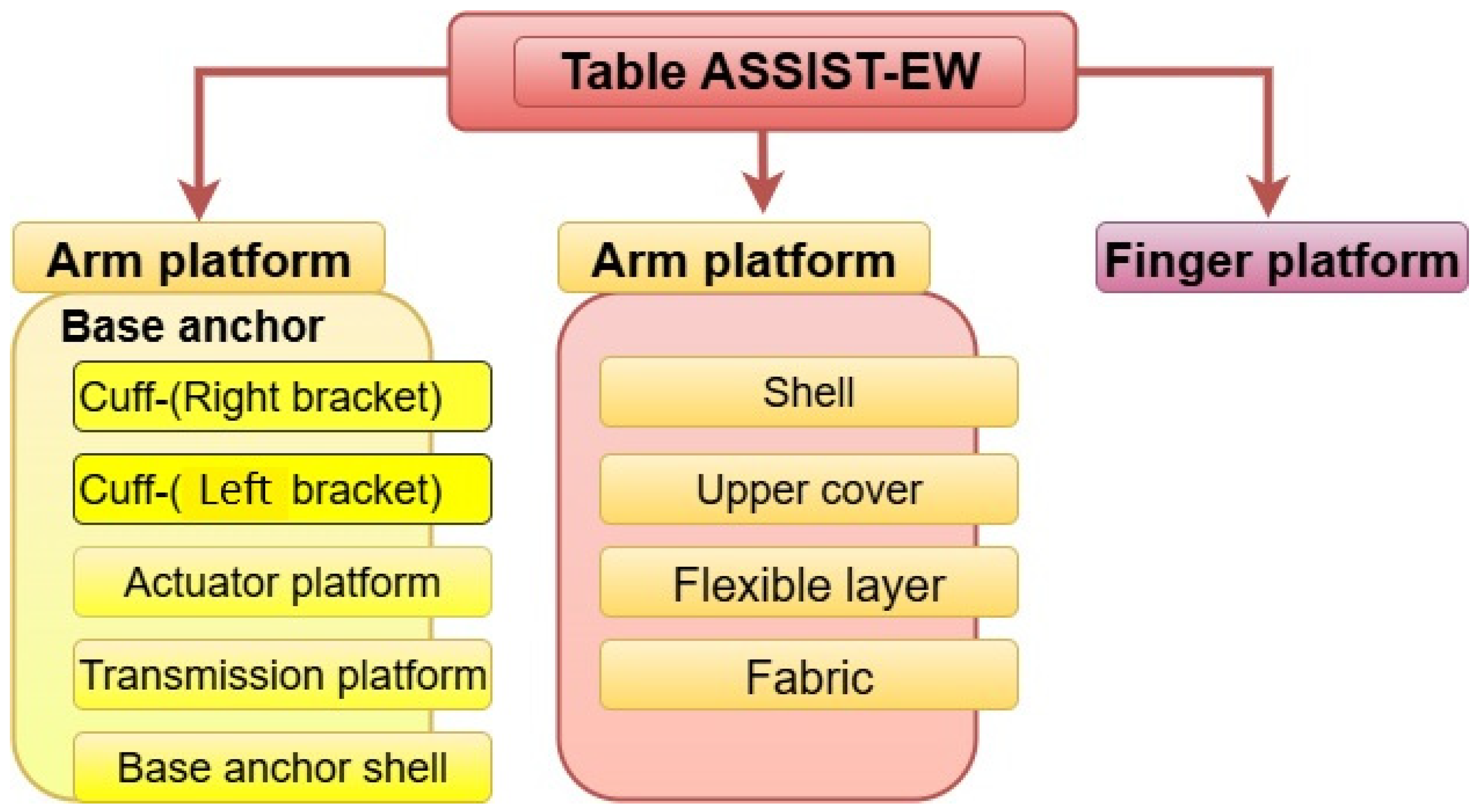
Figure 7 shows the scheme of the design solution in terms of components with the arrangement and interconnectivity of the main components that constitute the device. The wrist platform is composed of a shell with a flexible part and fabric that interact with the human wrist. The arm platform is composed of the base anchor, actuator platform, and the transmission platform. The base anchor is attached with the left and right cuff brackets. The mechanical design of the three platforms is shown in Figure 8, referring to the conceptual schemes in Figure 6 and Figure 7.

2.3. Mechanical Design

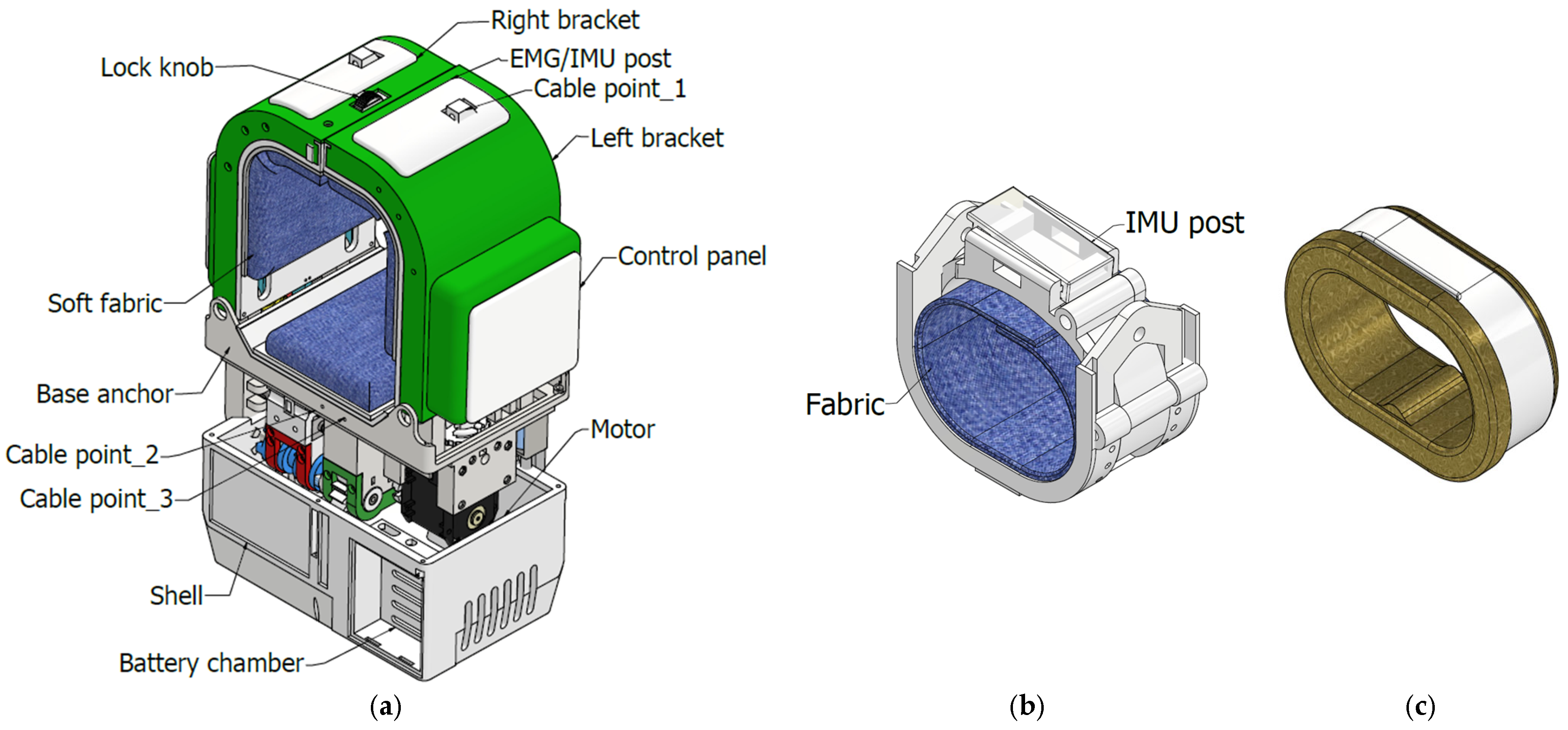
Figure 8 shows a CAD model of the mechanical design of the Table ASSIST-EW device composed of the three abovementioned platforms. Figure 8a shows the arm platform as the main part with a shape for table positioning. The wrist platform in Figure 8b is the actuating point of the device since the arm extension and flexion cable pulls on it during the exercise. The finger platform in Figure 8c consists of a shell and inner flexible layer that interacts with the two middle fingers. It is approximately 20 × 35 × 55 mm.
Figure 9 shows the CAD model of the wrist platform with dimensions of 39 × 67 × 71 mm. It is characterized by cable eyes and connection points for flexion and extension cables. Its design is made of a shell, a flexible layer, fabric, and an upper cover which houses the inertia measurement unit (IMU) sensor. Within the upper cover there is a hole that allows the wrist flexion cable to run to the finger platform.
The arm platform is shown in Figure 10 with a dimension of 103 × 202 × 232 mm. The opening part for positioning the arm within the platform is designed with a size of 88.1 × 87.2 mm. The aperture height of 87.2 mm is adjustable to suit different arm sizes. The shell is made of hard plastic material whereas the inner part of the cuff is made of fabric and foam embedded with an inflatable bladder that will inflate, as a secondary arrangement to adjust and fit the arm platform to different user arm sizes. Other features of the arm platform include the cuff brackets which open speedily by the action of the opening knob and quick lock when closed. There are cable connection points from where the actuation cable emerges from the arm platform and terminates at the wrist platform and at the finger platform. On the arm platform, there is a two-faced structure as the base anchor. It is covered by a shell properly shaped for positioning on a table.
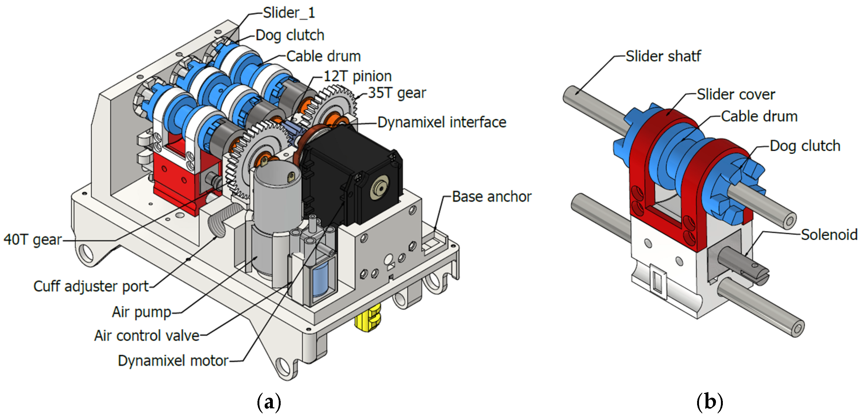
Figure 11 shows the base anchor frame with its components. One side hosts the transmission box, and the other side houses the actuator.
The transmission box, the actuating cables, electrical and signal wires, and the air pipes for inflating the cuffs are housed and routed in a compact solution. The actuator includes the motor, gears, pump, control valve, and solenoids. Each cable drum is sized so that the corresponding cable can be wound on it. There are three cable drums and each one is mounted on a slider with dog clutches at either end to enable quick engagement with, or release from, the gear shaft. The sliding motion is produced by the solenoids which are also embedded in the slider, as shown in Figure 11b. To ensure co-axiality between the cable drum shafts and the gear shaft, two guide shafts are provided, namely one on the hole drilled through the center of the drum shaft and the other through a hole on the slider body, both at a running fit clearance. With the capability of the slider to be engaged and disengaged thanks to the solenoids, each cable drum can be engaged and disengaged independently with their respective gear shafts. During active mode, the autonomy of the drums also enables the adjustment of cable length and tension to assist different exercise routines for different user needs.

2.4. Performance Analysis

A performance analysis is carried out to prove the smooth well-controlled motion during active mode and the user friendliness and efficiency of the device. The analysis includes the identification of the device motion range and force analysis.
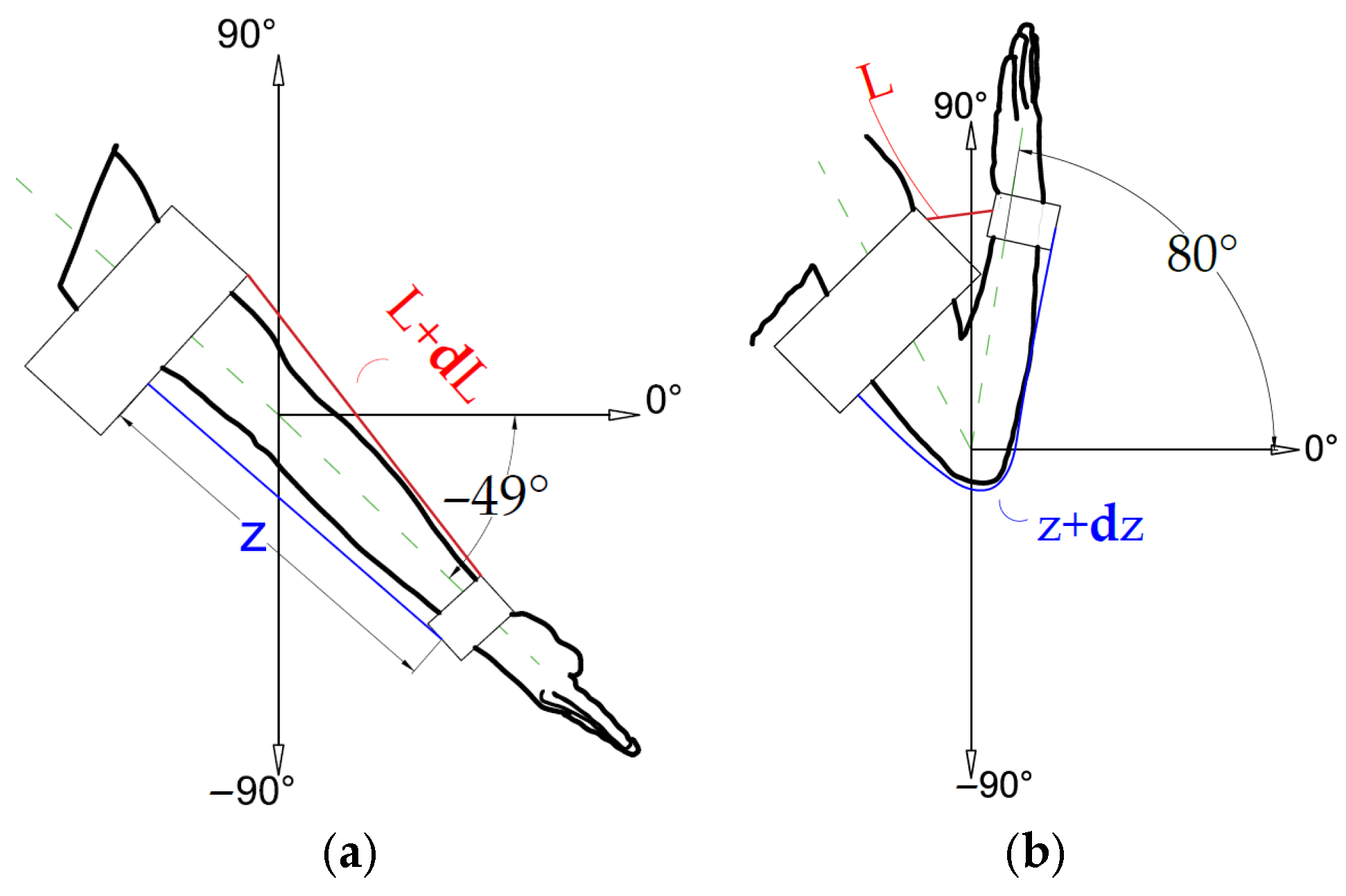
The range of motion is considered fundamental for the arm and wrist, giving the amount of cable to be used during exercise. The range of motion for the full flexion and extension of the arm and of the wrist varies for different individuals because of the different lengths of the upper limb. Nevertheless, the angular range and size ratio of upper limbs are almost similar for individuals with average limbs. Figure 12a,b shows the expected range of motion for an arm when fully extended and fully flexed, respectively. The arm usually has an angular range of motion of 129°. According to the chosen orientation, the range can be prescribed from −49 to 80° [6,31], as shown in Figure 12, where l + δl represents the length of the flexion cable and z + δz is the length of the extension cable.
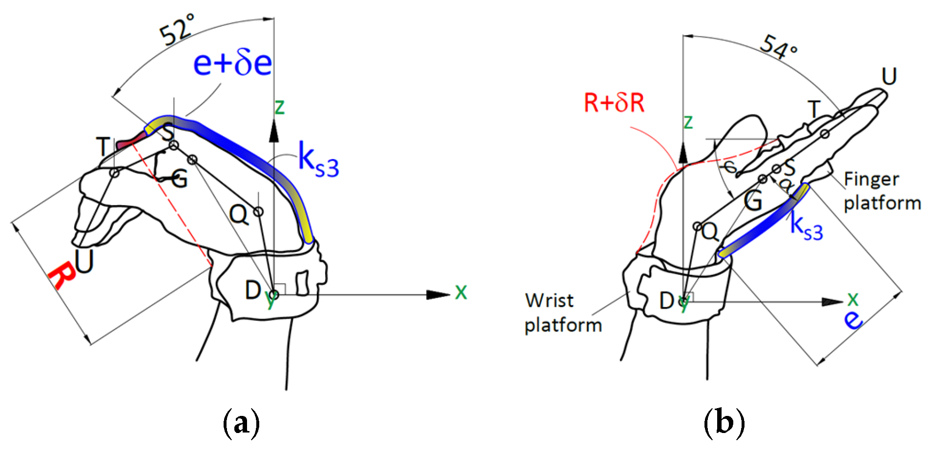
The scheme of the assisted motion of the wrist is shown in Figure 13, where the pivotal point is indicated as D. The cable anchor point is indicated as T, whereas the center of mass is G. The motion range can be considered to be about 106° for the angle of the QS line when it rotates about the pivotal point D. Its range can be from 52° to 54° around the Y-axis in a clockwise movement of the wrist. When only elbow flexion is commanded, there is no wrist flexion, but the wrist is flexed during the full exercise when planned up to an angle of 54 deg. at the most.
The length of cables for extension and flexion varies as a function of the arm size and the wrist motion. Some sections of the cable retract into the arm platform during flexion and are released during extension. The length of the cable may vary also depending on the limb size of the users. Figure 12 and Figure 13 show the lengths of the actuating cables as L, z, e, and R. The longest length of cables are given as (L + δL), (z + δz), (R + δR), and (e + δe) with the length variation in the cables indicated as δL, δz, δe, and δR. Table 1 lists the values of the lengths of the cables that were determined during a testing campaign.
The tension of the cable is kept almost constant by controlling the driving torque to ensure the proper pulling tension of the cables, which is monitored through the servomotor torque. To accommodate users with different arm sizes, the cable length is sized properly as discussed above to consider the length variation in the cable as a function of the assisted articulation movements and arm sizes.

3. Results

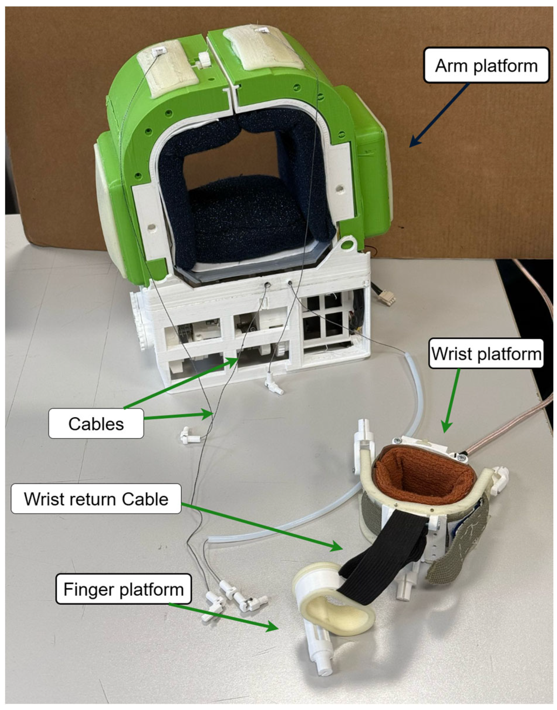
A prototype is built in accordance with the mechanical design in Figure 4, Figure 5, Figure 6, Figure 7, Figure 8, Figure 9, Figure 10, Figure 11, Figure 12 and Figure 13. It is made of structure parts that are printed in 3D using Polylactic Acid (PLA) and in Thermoplastic Polyurethane (TPU) for parts interfacing with the human body. Figure 14 shows the arm, wrist, and finger platforms of the built prototype with a total weight of about 1.5 kg and with a size of 103 × 202 × 232 mm for the arm platform. In Figure 14, the wrist return cable is also shown as an elastic band that extends the wrist once the wrist flexion cable is relaxed.
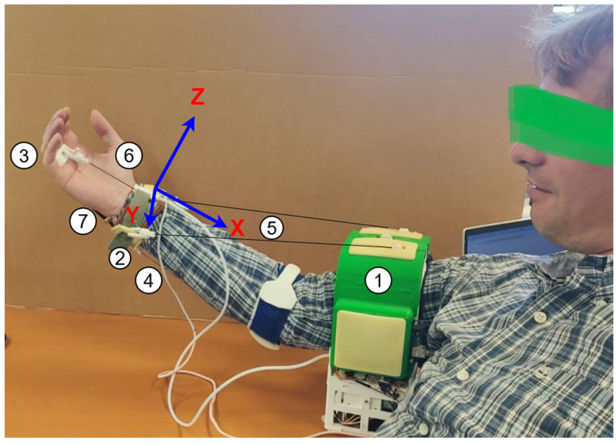
Figure 15 shows the Table ASSIST-EW device on a user arm ready for the test exercise. The inner side of the cuff brackets on the arm platform is lined with soft fabric that covers foam material embedded with an inflatable bladder. The actuation cables for flexion and extension and the wrist flexion cable are made of 1 mm diameter fishing cable capable of carrying 9 kg of tension force. The wrist return cable is a ductile fabric with a spring constant of approximately 382 Nm. A reference frame XYZ is attached to the wrist platform in correspondence with the IMU sensor, while a reference frame xyz is located on the elbow joint.
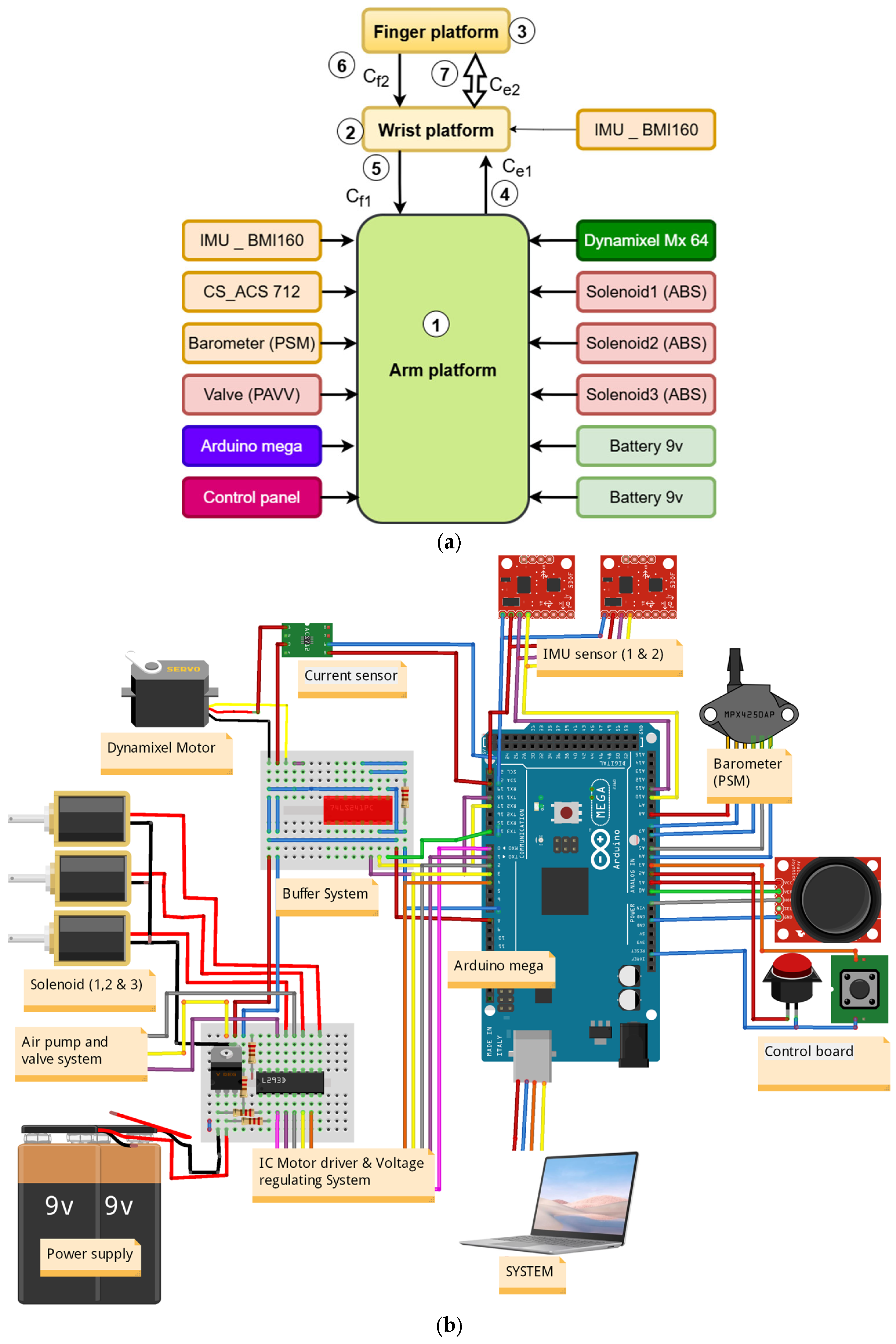
Figure 16 shows the design of the electronic circuit as a scheme in Figure 16a and as implemented in the prototype in Figure 16b. Power is supplied by either a battery or a DC source of 12–18 V to both the motor driver IC and the voltage regulation unit. The regulator outputs 12 V to operate the solenoids 1, 2, and 3, the pump, the valve, and the buffer system that controls and powers the Dynamixel MX-64 motor [32]. An Arduino microcontroller coordinates the device operations by sending control signals and receiving feedback from various sensors. A current sensor monitors power consumption, while one inertial measurement unit (IMU) tracks the orientation and movement of the wrist.
The second IMU is installed on the arm platform to monitor the stationary unit of the device on the table. The pump inflates the cuff’s internal bladder, and the valve deflates it as needed. A barometric sensor measures internal cuff pressure to maintain user comfort. The control panel works as a user interface, allowing an operator to manage the device. Figure 16a shows the block diagram of the device design with the microcontroller, sensors, and the actuator installed in the arm platform. A second IMU sensor is installed on the wrist platform to monitor the motion of the forearm. The arm extension cable Ce1 (4) in Figure 16a works together with arm flexion cable Cf1 (5). In the same manner, the wrist flexion cable Cf2 (6) works together with the wrist return cable/band Ce2 (7), since they link the wrist platform to the finger platform.
Figure 17 shows the hardware design in the prototype referring to Figure 16. A joystick is mounted on the control panel to control the motor when the device is not in automatic mode. The switch buttons assist the engagement of the cable drum with the gears. The location of the air pump is also shown in Figure 17a together with the buffer system for the control and energization of the Dynamixel motor. The maximum torque of the selected motor is 6 Nm, but the device is programmed not to exceed 2 Nm as the maximum driving torque. Safety during tests is ensured by the above threshold of 2 Nm driving torque and by a stop bottom in the control panel, as shown in Figure 17b.

Experimental Validation

The prototype of the Table ASSIST-EW device is tested using lab exercises within the range permissible by the elbows of the recruited volunteers. The simultaneous exercise of the wrist and elbow depends on the user, otherwise each exercise can conducted independently. The assisting device is placed on the table to only allow the forearm to flex from the tabletop horizon which corresponds to a position from 0 to a position of 90°, as illustrated in Figure 12. In a standing position, the arm could be flexed and extended for a range up to 129°.
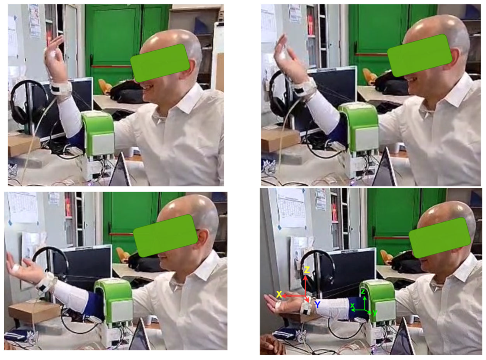
The testing mode for the experimental validation is planned to flex and extend both the arm and wrist simultaneously as in the test in Figure 18. The reported test results in Figure 19, Figure 20, Figure 21 and Figure 22 refer to an illustrative example like in Figure 18 from tests that are acquired in a testing campaign with 14 volunteers.
A test is run by a volunteer with a properly designed protocol as a step-by-step procedure. At first, the device cuff brackets are open, then the user places the arm, and the brackets are closed. Once the wrist platform, the finger platform, and elbow guide are worn correctly, the cables are drawn from the arm platform to the wrist platform. When the cables are secured to their respective attachments, they are tensed up to prevent slackening and intertwining at the drum. With the action of the joystick, a dry run is performed to ensure that the user does not feel any discomfort while the device runs the arm through the exercise motion range. Then an exercise program is loaded for the arm following a smooth well-controlled motion exercise.
The control computer displays a real-time acquisition with plots during the test session with a volunteer. The numerical data of these plots are collected and stored in an Excel file on a computer. The acquired data includes the Cartesian components of the linear acceleration, angular velocity, and angular displacement of the forearm. The data acquisition rate is set up at 100 Hz. Repeatability can be estimated at +/−0.3 deg. due to the resolution of the used servomotors. However, it looks not to be significant considering a human anatomy with motion tremors and accuracy.
Before the data acquisition, the participant signs a consensus form, which later will also contain information related to the acquired data stored on the computer. At the end of a test, the form will also report comments on user comfort and the effectiveness of the device as experienced by a tested volunteer.
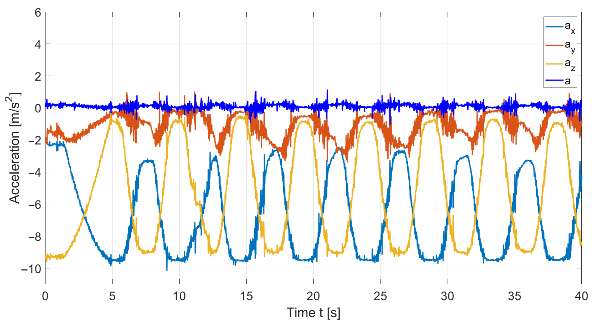
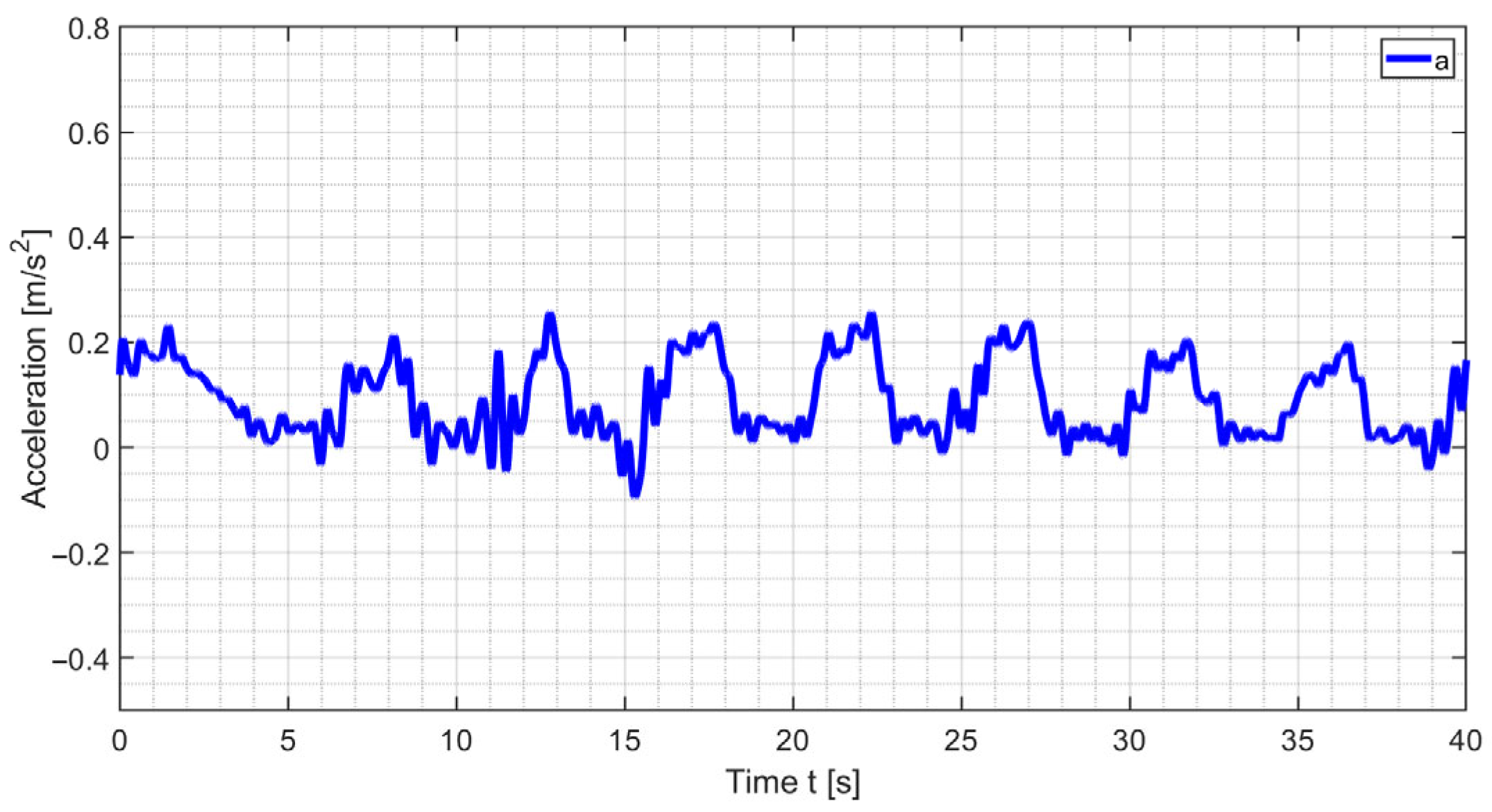
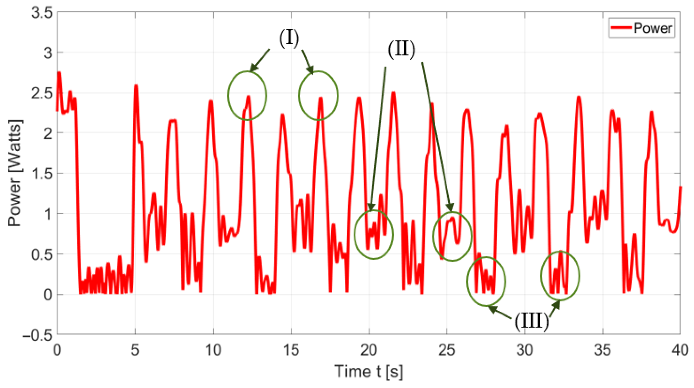
Figure 18 shows a snapshot of the Table ASSIST-EW device during a lab test exercise with a volunteer. Figure 19, Figure 20, Figure 21 and Figure 22 show test results in terms of angles, acceleration components, the magnitude of the acceleration, angular velocity, and power consumption.
The elbow angles with respect to the IMU reference frame, shown in Figure 15 and Figure 18, can be calculated with the angular displacements roll and pitch as
r o l l = t a n 1 a y a x 2 + a z 2
p i t c h = t a n 1 a x a x 2 + a z 2
The magnitude of the acceleration can be calculated by
a = a x 2 + a y 2 + a z 2
Gravity-free acceleration is calculated as
a n e t = a g
Power consumption is computed using the measured current and the voltage supply as
P = I V
Total used energy is computed from power consumption for the duration of a test by
E = t 0 t f P   d t
Figure 19 shows the acquired pitch and roll angles during a consistent and repetitive motion of an exercise session with a duration of 40 s. The period of one cycle is approximately 5 s. The pitch range of motion spans from 15° to 85°, while the roll ranges from 0° to −10°. The edges of the plot are rounded, indicating smooth transitions between flexion and extension when the device slowed down, stopped, and then reversed. This gives evidence of gentle angle–time evolution with deceleration at the proximity of points when flexion changes to extension.
From Figure 20, the following can be noted: The X-component of acceleration alternates between −9.1 and −1.8 m/s2; the Z-component fluctuates between −9.5 and −3 m/s2, and the Y-component varies between −2 and 0.2 m/s2. The Z-component of acceleration tends to complement the X-component, indicating that the acceleration occurs mainly within the XZ-plane, which is the sagittal plane of the arm. Referring to Figure 20, the motion performance is measured by the IMU sensor placed at the wrist platform, giving the above angles and the X, Y, and Z components of acceleration. The acceleration magnitude a is computed free of gravity g = 9.81 m/s2 using Equations (3) and (4), with the results shown in Figure 21. Though the acceleration plot is noisy and intermittently spiked, Figure 21 shows that the acceleration magnitude ranges between 0.03 and 0.3 m/s2, denoting very smooth assisted motion.
Referring to Figure 22, a repetitive cycle is observed in the power consumption plot, occurring at approximately 9.3 s intervals, which corresponds to the flexion–extension cycle of the arm. The acquired power consumption data is noisy even though it was filtered using a Butterworth low-pass filter at a sampling frequency of 100 Hz and by cutting off frequencies higher than 2 Hz. The average consumed electric energy is experienced as 58 Joule during an exercise of 40 s. There are three characteristic features of the plot that are marked in the plot zone as (I), (II), and (III):
(I)
These peaks represent the highest power consumption during the exercise cycle. They occur during arm flexion, when the flexion cable pulls and lifts the arm against gravity, necessitating a corresponding increase in energy demand. Additional power is also required when the wrist flexion cable works against the resistance of the elastic return cable. During this phase, the arm’s angular motion ranges from 10° to 90°, with power consumption between 2.2 and 2.7 W.
(II)
These peaks correspond to the lowering of the arm that is associated with arm extension. This occurs when the angle decreases from 90° to 45°, during which power is required to decelerate the arm and to bring it to a stop before reaching the lower limit. Power consumption during this phase ranges from 1.0 to 1.5 W.
(III)
These regions correspond to the transition between arm extension and flexion. This occurs at approximately 10°, when the arm comes to rest. Power consumption during this phase ranges from 0.2 to 1.2 W.
The test results show satisfactory motion assistance to well characterize the efficiency of the proposed design. The functional evaluation of acquired data in Figure 19, Figure 20, Figure 21 and Figure 22 in terms of the angles of movement, acceleration, and energy consumption has been reported and discussed as a proof-of-concept for the feasibility of the operation performance.
The device operation proved to be intuitive because it supports natural movement patterns, it is reactive to user intent with smooth human–machine interaction, and it provides clear motion feedback during operation. In addition, the device design is ergonomic because it is tailored to support the user’s body comfortably with proper material and shapes of parts in contact with the arm, such as the cuffs that are adjustable and inflatable to ensure no strain on the skin during exercise mode. The user-oriented easy operation is ensured by the fact that the control strategy is designed with natural kinematic patterns and minimal cognitive demand, allowing users to operate the device with minimal training or external aids. The volunteers gave positive feedback comments on those features during the testing campaign.

4. Conclusions

The structure of the Table ASSIST-EW device is designed following the analyzed design requirements with inspiration and experience also from lab testing campaigns with the L-CADEL design. In terms of adaptability, the cuffs in the arm platform are adjustable to different user arms with soft inflatable fabric making it ergonomic. This device is designed with arm platform dimensions of 103 × 202 × 232 mm, making it compact and easy to transport. The materials for the main structure of the device include market products and materials such as PLA, TPU, fabric, and foam. The cuffs are designed to be easy to use with a quick lock and release mechanism when the knob is pushed. The Table ASSIST-EW device is designed to perform many exercises thanks to gears, pinions, and solenoid switches enabling different options in motion during its operations. A prototype is tested, successfully matching requirements such as user comfort, structural effectiveness, and operation performance. Although no clinical evaluation has been reported in this paper and clinical metrics are not used, the functional evaluation has been discussed as a proof-of-concept for the feasibility of the operation performance.
The limitations of the current solution of the Table ASSIST-EW device can be identified in its design issues, related to its size and weight, and in its operation features, related to its assisted motion with no close-loop control feedback, clinical assessment with consistent testing campaign, and clinical–medical sensing of the assisted motion.
Future work will aim to improve the prototype further to meet user expectations mainly in comfort and easy usage, and to promote widespread adoption in clinical trials. Planned activities include comprehensive testing campaigns, such as clinic evaluations, user feedback collection, and clinical trials. Additionally, efforts will be directed toward reducing the overall mass of the device to values below 0.5 kg to enhance usability and wearability.

Author Contributions

Conceptualization, E.U.O. and M.C.; methodology, E.U.O. and M.C.; software, E.U.O.; validation, E.U.O. and M.C.; formal analysis, E.U.O. and M.C.; investigation, E.U.O. and M.C.; resources, M.C.; data curation, E.U.O.; writing—original draft preparation, E.U.O. and M.C.; writing—review and editing, E.U.O. and M.C.; visualization, E.U.O.; supervision, M.C.; project administration, M.C.; funding acquisition, M.C. All authors have read and agreed to the published version of the manuscript.

Funding

This research was funded by grant P2022A4ELB from the project ASSIST of the Italian 2022 PRIN-PNRR funding program of the Italian Ministry of University and Research.

Institutional Review Board Statement

The study was conducted in accordance with the Declaration of Helsinki and approved by the Institutional Ethics Committee of Policlinico di Tor Vergata, Rome, with protocol code RS. 197.22 on 15 November 2022.

Informed Consent Statement

Informed consent was obtained from all subjects involved in the study.

Data Availability Statement

Data is unavailable due to privacy and ethical restrictions.

Acknowledgments

We acknowledge thankfully the grant P2022A4ELB from the project ASSIST of the Italian 2022 PRIN-PNRR funding program.

Conflicts of Interest

The authors declare no conflicts of interest. The funders had no role in the design of the study; in the collection, analyses, or interpretation of data; in the writing of the manuscript; or in the decision to publish the results.

References

  1. Bajaj, N.M.; Dollar, A.M. Design and preliminary evaluation of a 3-DOF powered prosthetic wrist device. In Proceedings of the 2018 7th IEEE International Conference on Biomedical Robotics and Biomechatronics (Biorob), Enschede, The Netherlands, 26–29 August 2018; pp. 119–125. [Google Scholar] [CrossRef]
  2. Fan, H.; Wei, G.; Ren, L. Prosthetic and robotic wrists comparing with the intelligently evolved human wrist: A review. Robotica 2022, 40, 4169–4191. [Google Scholar] [CrossRef]
  3. Bian, H.; Chen, Z.; Wang, H.; Zhao, T. Mechanical design of EFW Exo II: A hybrid exoskeleton for elbow-forearm-wrist rehabilitation. In Proceedings of the 2017 International Conference on Rehabilitation Robotics (ICORR), London, UK, 17–20 July 2017; pp. 689–694. [Google Scholar] [CrossRef]
  4. Bok Hong, M.; Yoon, D.; Park, J.; Kim, K. KULEX-Wrist: Design and analysis of linkage-driven exoskeleton for wrist assistance. J. Mech. Des. 2024, 146, 083303. [Google Scholar] [CrossRef]
  5. Wu, X.; Zou, Y.; Zhang, Q.; Zhang, B.; Gu, X.; Zhang, J. Design and experimental research of cable-driven upper-limb rehabilitation robot. In Intelligent Robotics and Applications; Liu, X., Nie, Z., Yu, J., Xie, F., Song, R., Eds.; Springer: Cham, Switzerland, 2021; Volume 13013. [Google Scholar] [CrossRef]
  6. Cael, C. Functional Anatomy: Musculoskeletal Anatomy, Kinesiology, and Palpation for Manual Therapists with Navigate Advantage Access; Jones & Bartlett Learning: Burlington, MA, USA, 2022; ISBN 978-1284234800. [Google Scholar]
  7. Ceccarelli, M. Challenges in service robot devices for elderly motion assistance. Robotica 2024, 42, 4186–4199. [Google Scholar] [CrossRef]
  8. Ceccarelli, M.; Cruz, C.M.; Ofonaike, E. Problems and design for a cable-driven device for elbow-wrist assistance. In Proceedings of the 2025 IEEE International Conference on Mechatronics (ICM), Wollongong, Australia, 28 February–2 March 2025; pp. 1–6. [Google Scholar] [CrossRef]
  9. Ceccarelli, M.; Kotov, S.; Ofonaike, E.; Russo, M. Test results and considerations for design improvements of L-CADEL v.3 elbow-assisting device. Machines 2024, 12, 808. [Google Scholar] [CrossRef]
  10. Cheng, H.H.; Kwok, T.M.; Yu, H. Design and control of the portable upper-limb elbow-forearm exoskeleton for ADL assistance. In Proceedings of the 2023 IEEE/ASME International Conference on Advanced Intelligent Mechatronics (AIM), Seattle, WA, USA, 28–30 June 2023; pp. 343–349. [Google Scholar] [CrossRef]
  11. Cornejo, J.; Huamanchahua, D.; Huamán-Vizconde, S.; Terrazas-Rodas, D.; Sierra-Huertas, J.; Janampa-Espinoza, A.; Gonzáles, J.; Cardona, M. Mechatronic exoskeleton systems for supporting the biomechanics of shoulder-elbow-wrist: An innovative review. In Proceedings of the 2021 IEEE International IOT, Electronics and Mechatronics Conference (IEMTRONICS), Toronto, ON, Canada, 21–24 April 2021; pp. 1–9. [Google Scholar] [CrossRef]
  12. Delgado, P.; Yihun, Y. Integration of task-based exoskeleton with an assist-as-needed algorithm for patient-centered elbow rehabilitation. Sensors 2023, 23, 2460. [Google Scholar] [CrossRef] [PubMed]
  13. Dias, E.A.F.; Andrade, R.M. Design of a cable-driven actuator for pronation and supination of the forearm to integrate an active arm orthosis. Proceedings 2020, 64, 4. [Google Scholar] [CrossRef]
  14. Jeong, J.; Yasir, I.B.; Han, J.; Park, C.H.; Bok, S.-K.; Kyung, K.-U. Design of shape memory alloy-based soft wearable robot for assisting wrist motion. Appl. Sci. 2019, 9, 4025. [Google Scholar] [CrossRef]
  15. Laribi, M.A.; Ceccarelli, M.; Sandoval, J.; Bottin, M.; Rosati, G. Experimental validation of light cable-driven elbow-assisting device L-CADEL design. J. Bionic Eng. 2022, 19, 416–428. [Google Scholar] [CrossRef]
  16. Lin, T.-Y.; Chen, Z.-Y.; Chang, J.-Y. Design and implementation of a cable-driven wrist exoskeleton with enhanced adaptability. In Proceedings of the IET International Conference on Engineering Technologies and Applications (ICETA 2024), Taipei, Taiwan, 25–27 October 2024; pp. 146–147. [Google Scholar] [CrossRef]
  17. Maciejasz, P.; Eschweiler, J.; Gerlach-Hahn, K.; Jansen-Troy, A.; Leonhardt, S. A survey on robotic devices for upper limb rehabilitation. J. NeuroEng. Rehabil. 2014, 11, 1–29. [Google Scholar] [CrossRef]
  18. Meattini, R.; Palli, G.; Melchiorri, C. Experimental evaluation of a sEMG-based control for elbow wearable assistive devices during load lifting tasks. In Proceedings of the 2017 International Conference on Rehabilitation Robotics (ICORR), London, UK, 17–20 July 2017; pp. 140–145. [Google Scholar] [CrossRef]
  19. Mobedi, E.; Kim, W.; Leonori, M.; Tsagarakis, N.G.; Ajoudani, A. Design and control of an assistive device for elbow effort-compensation. IEEE ASME Trans. Mechatron. 2023, 28, 3446–3457. [Google Scholar] [CrossRef]
  20. Wei, F.; Luo, K.; Zhang, Y.; Jiang, J. Structural design and kinematic analysis of cable-driven soft robot. Actuators 2024, 13, 497. [Google Scholar] [CrossRef]
  21. Pang, Z.; Wang, T.; Wang, Z.; Yu, J.; Sun, Z.; Liu, S. Design and analysis of a wearable upper limb rehabilitation robot with characteristics of tension mechanism. Appl. Sci. 2020, 10, 2101. [Google Scholar] [CrossRef]
  22. Palazzi, E.; Luzi, L.; Dimo, E.; Meneghetti, M.; Vicario, R.; Luzia, R.F.; Vertechy, R.; Calanca, A. An affordable upper-limb exoskeleton concept for rehabilitation applications. Technologies 2022, 10, 22. [Google Scholar] [CrossRef]
  23. Sanjuan, J.D.; Castillo, A.D.; Padilla, M.A.; Quintero, M.C.; Gutierrez, E.E.; Sampayo, I.P.; Hernandez, J.R.; Rahman, M.H. Cable driven exoskeleton for upper-limb rehabilitation: A design review. Robot. Auton. Syst. 2020, 126, 103445. [Google Scholar] [CrossRef]
  24. Shi, K.; Song, A.; Li, Y.; Li, H.; Chen, D.; Zhu, L. A cable-driven three-DOF wrist rehabilitation exoskeleton with improved performance. Front. Neurorobot. 2021, 15, 664062. [Google Scholar] [CrossRef] [PubMed]
  25. Meng, Q.; Jiao, Z.; Yu, H.; Zhang, W. Design and evaluation of a novel upper limb rehabilitation robot with space training based on an end effector. Mech. Sci. 2021, 12, 639–648. [Google Scholar] [CrossRef]
  26. Vazzoler, G.; Camardella, C.; Gabardi, M.; Marcheschi, S.; Solazzi, M.; Berselli, G.; Frisoli, A. Design and performance assessment of a cable-driven, 3-DOFs exoskeleton for orthopedic and poststroke rehabilitation of the wrist. IEEE ASME Trans. Mechatron. 2025, 30, 3892–3903. [Google Scholar] [CrossRef]
  27. Wu, K.-Y.; Su, Y.-Y.; Yu, Y.-L.; Lin, C.-H.; Lan, C.-C. A 5-degrees-of-freedom lightweight elbow-wrist exoskeleton for forearm fine-motion rehabilitation. IEEE ASME Trans. Mechatron. 2019, 24, 2684–2695. [Google Scholar] [CrossRef]
  28. Zuccon, G.; Bottin, M.; Ceccarelli, M.; Rosati, G. Design and performance of an elbow assisting mechanism. Machines 2020, 8, 68. [Google Scholar] [CrossRef]
  29. Lau, D.; Pott, A.; Bruckmann, T. (Eds.) Cable-Driven Parallel Robots. In Mechanisms and Machine Science, Proceedings of the 7th International Conference on Cable-Driven Parallel Robots, Hong Kong, 8–11 July 2025; Springer: Cham, Switzerland, 2025; Volume 182. [Google Scholar] [CrossRef]
  30. Holzbaur, K.R.S.; Murray, W.M.; Delp, S.L. A model of the upper extremity for simulating musculoskeletal surgery and analyzing neuromuscular control. Ann. Biomed. Eng. 2005, 33, 829–840. [Google Scholar] [CrossRef]
  31. Patel, S.; Park, H.; Bonato, P.; Chan, L.; Rodgers, M. A review of wearable sensors and systems with application in rehabilitation. J. Neuroeng. Rehabil. 2012, 9, 21. [Google Scholar] [CrossRef]
  32. Robotis. Dynamixel MX-64 Series. Robotis e-Manual. Available online: https://emanual.robotis.com/docs/en/dxl/mx/mx-64/ (accessed on 7 June 2025).
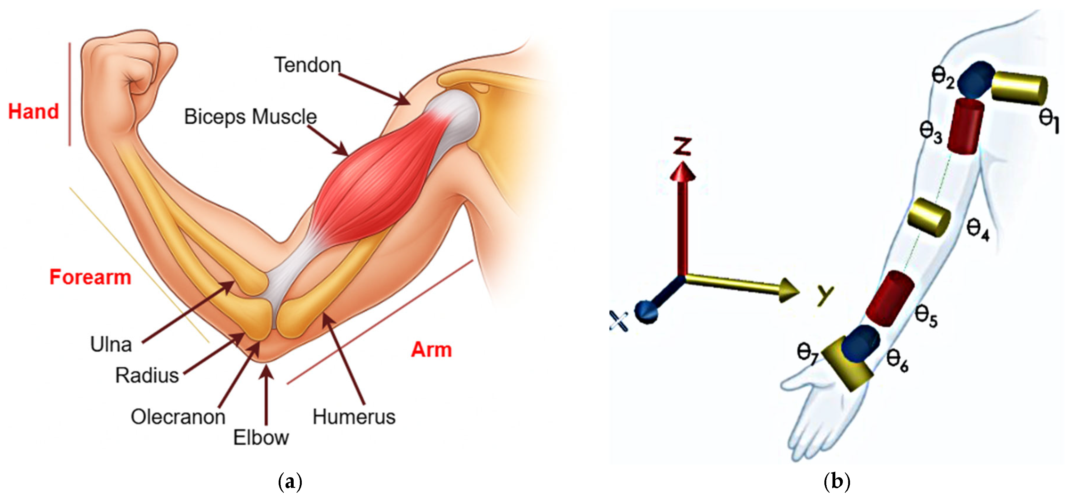
Figure 1. Anatomy of human arms [6]: (a) muscle skeleton structure; (b) a kinematic model.
Applsci 15 11482 g001
Figure 3. Structural effectiveness and control strategy as main requirements for elbow–wrist assisting devices.
Applsci 15 11482 g003
Figure 4. Scheme of mechanical design of the proposed elbow–wrist assisting device.
Applsci 15 11482 g004
Figure 5. Design scheme of the gear cable actuating system with gear directions during active mode.
Applsci 15 11482 g005
Figure 6. Design schemes for Table ASSIST-EW device: (a) conceptual design; (b) assembly circuit.
Applsci 15 11482 g006
Figure 7. Conceptual design of Table ASSIST-EW device in terms of components.
Applsci 15 11482 g007
Figure 8. Mechanical design of Table ASSIST-EW device: (a) arm platform; (b) wrist platform; (c) finger platform.
Applsci 15 11482 g008
Figure 9. CAD model with sizes for the wrist platform of Table ASSIST-EW device in Figure 8b.
Applsci 15 11482 g009
Figure 10. CAD model with sizes for arm platform of Table ASSIST-EW device in Figure 8a.
Applsci 15 11482 g010
Figure 11. Base anchor frame with its components within the arm platform in Figure 10: (a) whole design; (b) a slider unit.
Applsci 15 11482 g011
Figure 12. Scheme for arm motion assisted by Table ASSIST-EW device: (a) fully extended arm; (b) fully flexed arm.
Applsci 15 11482 g012
Figure 13. Scheme for wrist motion assisting by Table ASSIST-EW device: (a) fully flexed wrist; (b) fully extended wrist. (D: wrist platform anchor point; Q: wrist point at carpometacarpal joint; G: hand center of mass; S: metacarpophalangeal joint point; T: proximal interphalangeal joint point; U: fingertip).
Applsci 15 11482 g013
Figure 14. Prototype of Table ASSIST-EW device with the three platforms.
Applsci 15 11482 g014
Figure 15. Prototype of Table ASSIST-EW device worn on a user arm ready for test exercise. (1: arm platform; 2: wrist platform; 3: finger platform; 4: extension cable; 5: flexion cable; 6: wrist flexion cable; 7: wrist return cable).
Applsci 15 11482 g015
Figure 16. Design of the electronic circuit of the prototype of Table ASSIST EW device in Figure 15: (a) conceptual design; (b) implemented equipment.
Applsci 15 11482 g016
Figure 17. Prototype of Table ASSIST-EW device: (a) all the components; (b) control panel.
Applsci 15 11482 g017
Figure 18. Snapshot of a test with a volunteer during testing with Table ASSIST EW device.
Applsci 15 11482 g018
Figure 19. Acquired data of the test in terms of pitch and roll angles during a test like in Figure 18.
Applsci 15 11482 g019
Figure 20. Acquired data of the test in terms of acceleration components of wrist (ax, ay, and az are acceleration components and a is acceleration magnitude).
Applsci 15 11482 g020
Figure 21. Acquired data of the test in terms of acceleration magnitude for the X, Y, and Z components of Figure 20.
Applsci 15 11482 g021
Figure 22. Acquired values of power consumption during the exercise with Table ASSIST EW device.
Applsci 15 11482 g022
Table 1. Length of cables during operation test, Figure 12 and Figure 13.
Arm ConfigurationLength [mm]Length [mm]
Extended armL + dL = 371.0z = 217.8
Flexed armL = 41.0z + dz = 327.8
Flexion wrist R = 123.0e + de = 132.3
Extended wristR + dR = 220.0e = 82.3
Disclaimer/Publisher’s Note: The statements, opinions and data contained in all publications are solely those of the individual author(s) and contributor(s) and not of MDPI and/or the editor(s). MDPI and/or the editor(s) disclaim responsibility for any injury to people or property resulting from any ideas, methods, instructions or products referred to in the content.