Article

Simulation Study on the Magnetic Field Characteristics of a Permanent Magnet Motor for a Rim-Driven Device

1
Naval University of Engineering, Wuhan 430033, China
2
National Key Laboratory on Ship Vibration & Noise, Wuhan 430033, China
*
Authors to whom correspondence should be addressed.
Appl. Sci. 2025, 15(20), 11129; https://doi.org/10.3390/app152011129
Submission received: 2 June 2025 / Revised: 7 October 2025 / Accepted: 9 October 2025 / Published: 17 October 2025
(This article belongs to the Section Applied Physics General)

Abstract

The rim-driven device (RDD) integrates the motor and the impeller, which can achieve shaftless, modular, and integrated operation of the turbomachinery system and has broad application prospects. To reduce the axial length and radial thickness of the RDD, a motor with a thin-yoke wide-tooth fractional slot concentrated winding stator and a coreless Halbach permanent magnet array rotor is designed. Theoretical and finite element simulation analyses of its air gap magnetic field characteristics were carried out. The results show that, for the thin-yoke wide-tooth fractional slot concentrated winding permanent magnet motor, the harmonic magnetic field generated by the magnetic poles should mainly consider the magnetic field components produced by the interaction between the harmonic magnetomotive force of the magnetic poles and the constant air gap specific magnetic permeability, as well as the magnetic field components generated by the interaction between the fundamental magnetomotive force of the magnetic poles and the fundamental and second-order harmonic air gap specific magnetic permeability. The harmonic magnetic field generated by the current should mainly consider the magnetic field components produced by the interaction between the harmonic magnetomotive force with a small number of pole pairs (NOPP) and large amplitude generated by the current and the constant air gap specific magnetic permeability. Compared with radial magnetic flux density, tangential magnetic flux density has the same NOPP and frequency components, with a phase difference of 90°. The fundamental amplitude difference between them is larger, while the harmonic amplitude difference between them is smaller.

1. Introduction

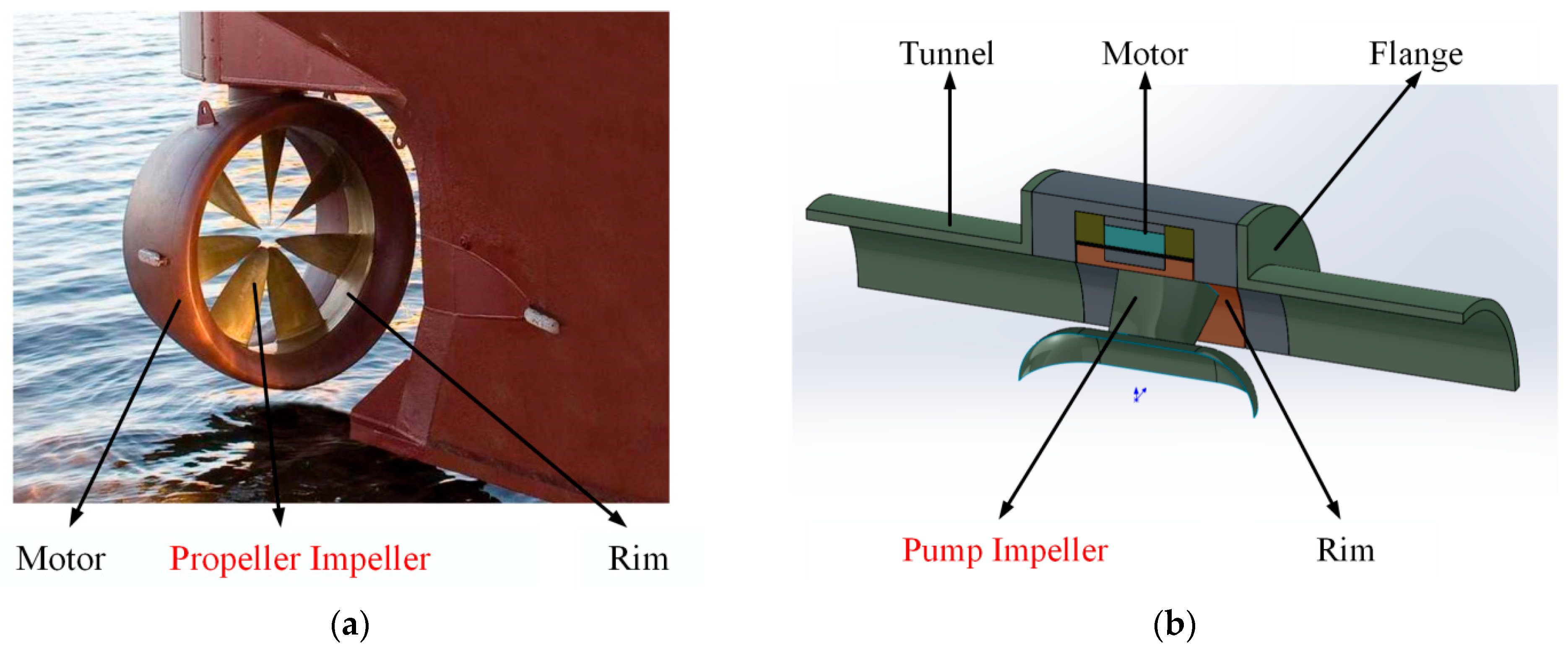
The “rim” in the rim-driven device (RDD), also known as rim-driven propeller (RDP) and rim-driven thruster (RDT), generally refers to the impeller rim. The impeller is a widely used energy conversion component in machinery, such as pump impellers and propeller impellers [1,2]. Ordinary impellers are usually driven by the engine through the transmission shaft and the hub, as shown in Figure 1a. This is a mechanical transmission method. The impeller of the RDD, however, is directly driven by the motor through the rim, thus eliminating the need for a transmission shaft. The motor rotor and the impeller rim are integrated, while the motor stator and the motor rotor achieve non-contact electromagnetic transmission through the air gap, as shown in Figure 1b. The RDD can achieve shaftless, modular, and integrated operation of the turbomachinery system, and has broad application prospects [1,2,3].
Classified by application, the RDD includes the ship thrust propeller and the pipeline transfer pump, as shown in Figure 2a,b, respectively.
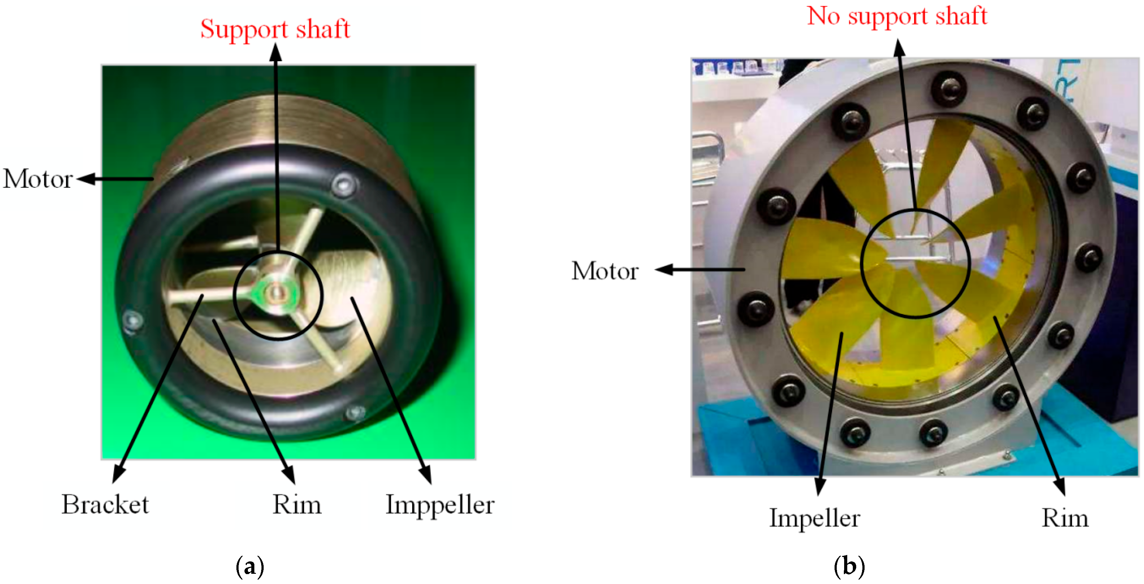
Classified by structure, the RDD includes RDD with a support shaft and RDD with no support shaft, as shown in Figure 3a,b respectively.
The RDD with a motor as the prime mover was first proposed by Kort in the German patent DE688114 in 1940 [4], but this design was only conceptual at the time. In recent years, with advancements in technologies such as motors, control, and bearings, RDDs have undergone rapid development as an innovative drive approach. In 2003, Piet from General Dynamics Electric Boat Company (United States) wrote an article detailing the manufacturing process of an RDD for ship propulsion and conducted tests on the prototype [5]. In the “Tango Bravo” program launched by the United States Navy in 2005, the shaftless rim-driven thruster was even regarded as a key technology for next-generation submarines.
The research on the key technologies of the RDD mainly includes the optimization on the hydrodynamic performance of the guide duct and impeller [6], the design of water-lubricated bearings [7], the integrated design of the motor and impeller [8], and the research on the sensorless control of the motor, as it is difficult to install a position sensor on the RDD [9]. As for the research on the motor type of RDD, Brown from Westinghouse Corporation in the United States completed a prototype of a 7.5 kW squirrel-cage rotor induction motor for a rim-driven thruster in 1989 [10], and Richardson from the University of Warwick in the United Kingdom completed a prototype of a 5 kW 3-phase 6-pole reluctance motor for a rim-driven thruster in 1995 [11]. However, both the induction motor and the reluctance motor schemes have the problems of excessive radial thickness of the motor, resulting in a large duct size and low hydrodynamic efficiency of the thruster [10,11]. RDDs have sheaths and anti-corrosion protective layers in the air gap, which lead to a large air gap size and reduced electromagnetic performance [10,11]. Permanent magnet motors do not require complex electrical excitation systems and have a relatively high power density. They have greater advantages in adapting to large electromagnetic air gaps and reducing the radial thickness of the motor through a multi-pole structure, and have gradually become the mainstream motor scheme for RDDs [12,13].
This paper presents the design of a permanent magnet motor for an RDD, which combines a thin-yoke wide-tooth fractional slot concentrated winding stator and a coreless Halbach permanent magnet array rotor, and conducts simulation research on its magnetic field characteristics.

2. Design of Permanent Magnet Motor for RDD

When the RDD is used as a pipeline transfer pump, there is only an internal flow field and no external flow field. However, when it is used as a ship thrust propeller, there are both internal flow field and external flow field. No matter what scenario it is used in, the RDD is expected to have a relatively small radial thickness and axial length.

2.1. Thin-Yoke Wide-Tooth Fractional Slot Concentrated Winding Stator

The armature winding end of a common motor is trumpet-shaped, which occupies a relatively large axial space, as shown in Figure 4a. The end winding structure of the fractional slot concentrated winding motor is simple, and the axial length of the motor is relatively small [14,15], as shown in Figure 4b.
The end of the fractional slot concentrated winding is short, which makes it very suitable for use in permanent magnet motors for RDDs. In the process of determining the motor slot and pole combination scheme, the goals were to have a large fundamental winding coefficient, fewer harmonic magnetomotive force components with small amplitudes, a small harmonic back electromotive force amplitude, and a small cogging torque. Considering the above factors comprehensively as well as the outer diameter of the impeller (in this paper, the outer diameter of the impeller is 250 mm), the 24-slot and 20-pole winding scheme was finally selected.
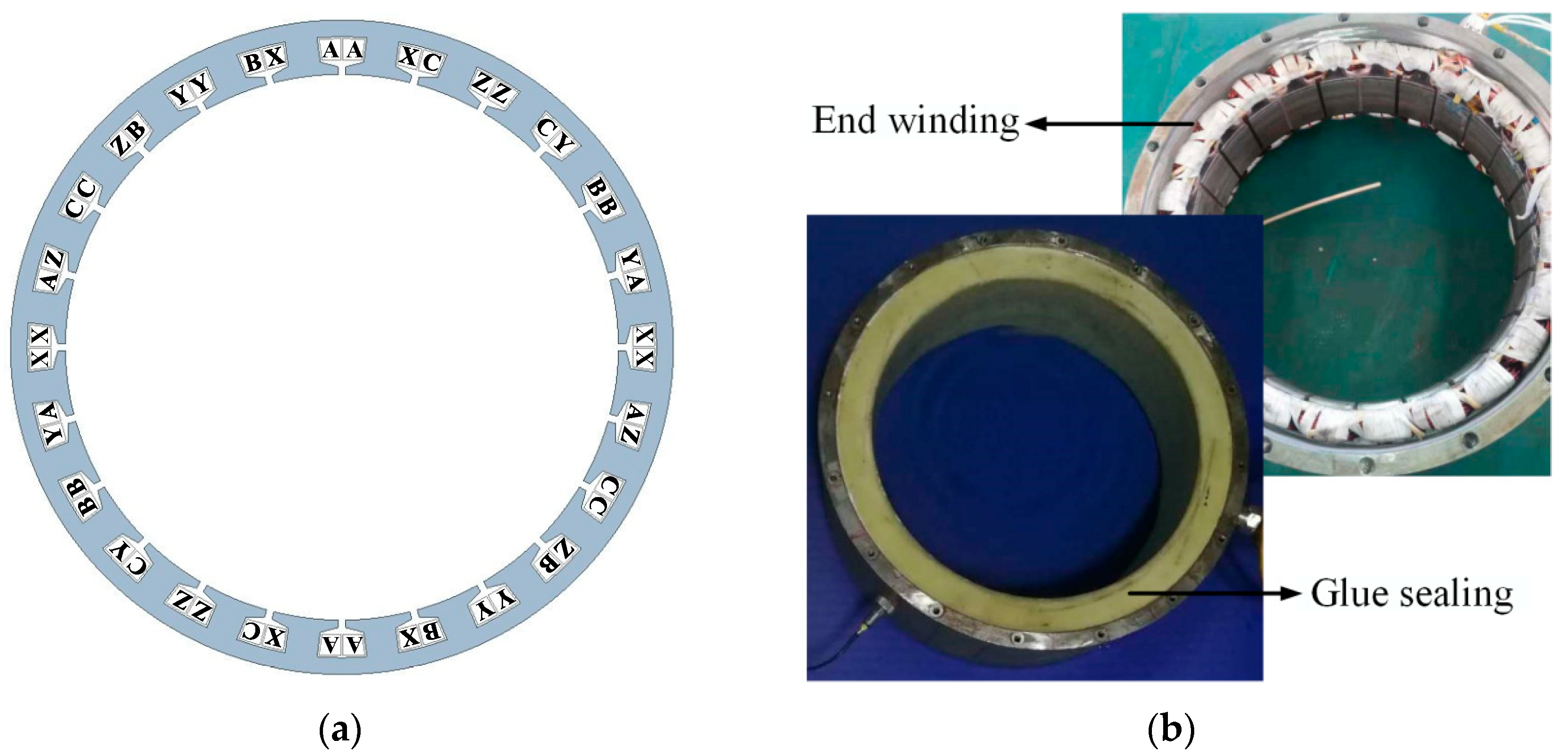
The arrangement of the three-phase windings is shown in Figure 5a. In the figure, coil sides A and X belong to the A-phase windings, coil sides B and Y belong to the B-phase windings, and coil sides C and Z belong to the C-phase windings. The currents in coil sides X, Y, and Z are equal in magnitude but opposite in direction to those in coil sides A, B, and C. Since the RDD operates in water, the windings are sealed with glue, as shown in Figure 5b.
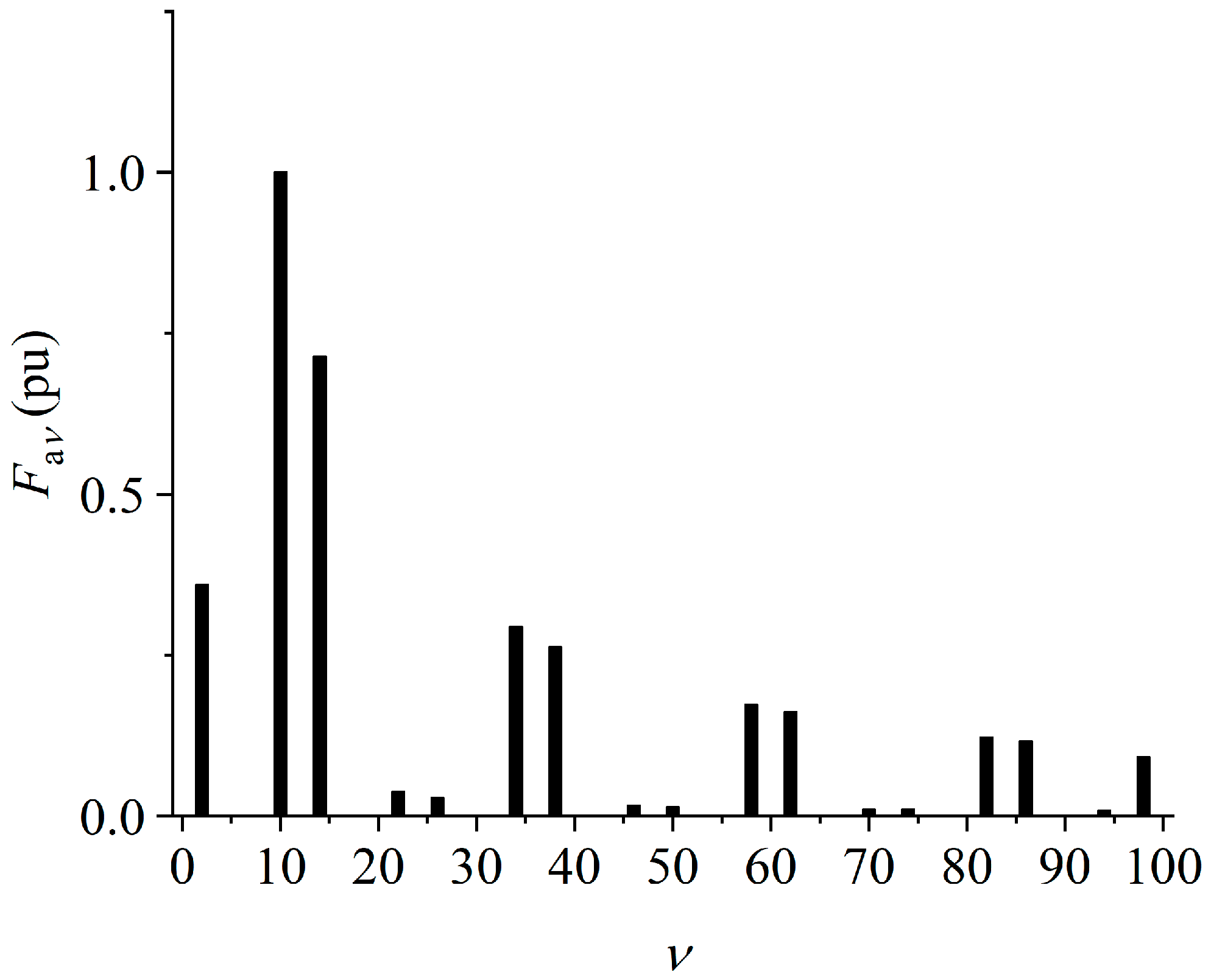
The per-unit value of the armature harmonic magnetomotive force of the 24-slot 20-pole fractional slot concentrated winding is shown in Figure 6, where ν represents the number of magnetomotive force pole pairs and F a v ( pu ) represents the per-unit value of the magnetomotive force.

2.2. Coreless Halbach Permanent Magnet Array Rotor

The magnetic poles of a common permanent magnet motor are usually composed of alternating permanent magnets of opposite polarity that are radially magnetized, as shown in Figure 7a. By embedding the tangentially magnetized permanent magnets as shown in Figure 7b into the permanent magnet arrangement of a common permanent magnet motor, a Halbach permanent magnet array can be formed [16], as shown in Figure 7c. Compared with the arrangement of ordinary permanent magnet, the Halbach permanent magnet array has a unilateral magnetic clustering effect, which can weaken the magnetic field on one side of the permanent magnet array and strengthen the magnetic field on the other side [17]. When the Halbach array is applied to permanent magnet motors, under the condition that the air gap magnetic field intensity is constant, the required thickness of the rotor back iron and magnetic poles is smaller than that of ordinary permanent magnet motors, and the radial thickness of the motor is also smaller.
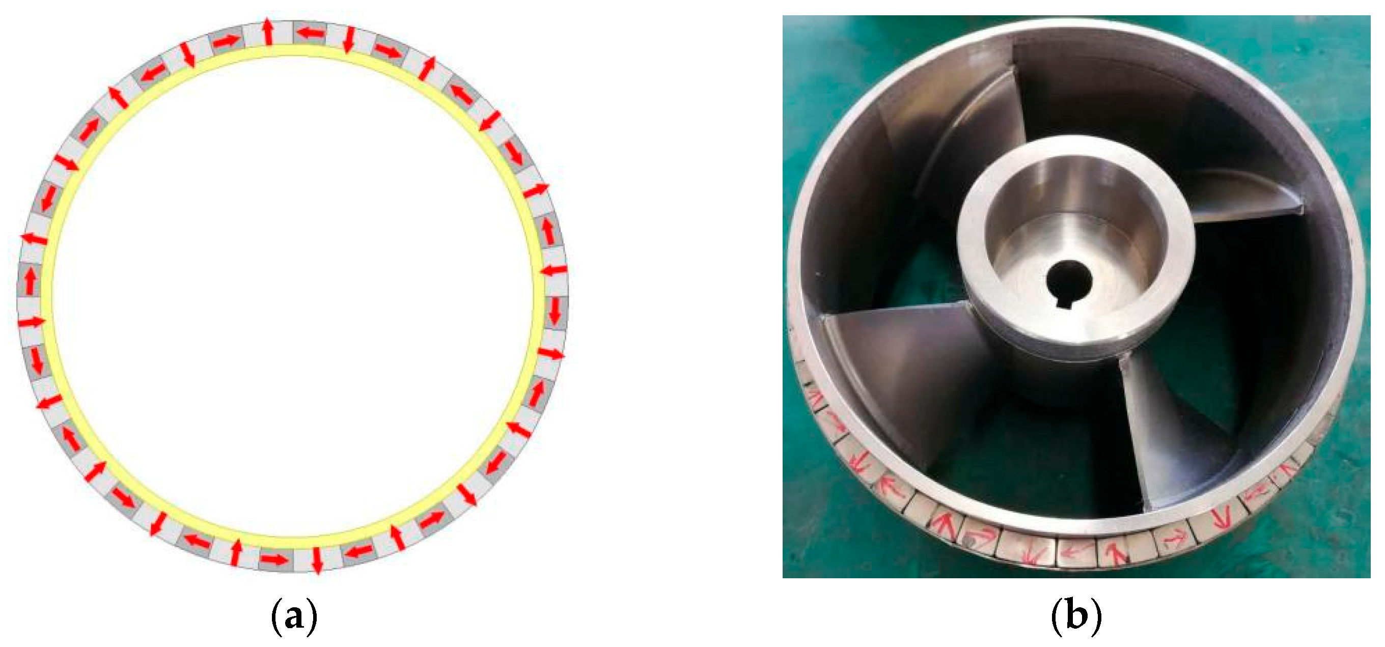
The permanent magnet motor rotor of an RDD usually operates in a water medium. The impeller blade and rim ring are generally made of anti-corrosion stainless steel, and to ensure the strength of the rotor, the stainless steel rim should have a certain thickness. The magnetic permeability of stainless steel is much lower than that of ferromagnetic materials. Meanwhile, for smooth operation of the RDD, the thickness of the rotor should be as small as possible. Therefore, in this paper, the rotor does not use conventional ferromagnetic materials. Instead, a coreless Halbach permanent magnet array rotor scheme is formed by combining a Halbach permanent magnet array with a unilateral magnetic clustering effect and a stainless steel rim ring. Each single permanent magnet is magnetized in parallel. The arrangement of the permanent magnets is shown in Figure 8, with arrows indicating the magnetization direction.
Ultimately, the design parameters of the permanent magnet motor for an RDD are shown in the Table 1 below.

3. Harmonic Analysis of Air Gap Magnetic Field Based on One-Dimensional Magnetic Circuit Method

The one-dimensional linear magnetic circuit method was the earliest approach used in motor design and analysis. It regards the air gap magnetic flux density of the motor as the product of the air gap magnetic potential and the air gap specific magnetic permeability. Although it gives insufficient consideration to complex geometry and material nonlinearity, it has the characteristics of clear concepts and logic [18].

3.1. Radial Air Gap Magnetic Flux Density

Under the no-load condition, the magnetic pole magnetomotive force can be expressed as [19]
f m θ , t = μ F m μ cos μ θ μ p ω 1 t φ m μ
In the formula, θ is the spatial mechanical angular displacement, p is the NOPP of the magnetic poles, μ is the NOPP of the harmonic magnetomotive force of the magnetic poles, ω 1 is the fundamental electrical angular frequency, F m μ is the amplitude of the magnetomotive force of the magnetic poles, φ m μ is the initial angular displacement of the magnetomotive force of the magnetic poles, and μ = p represents the fundamental magnetomotive force. The magnetomotive force of the magnetic poles is a function of time and space and is a traveling wave.
The distribution of the magnetomotive force of the magnetic poles along the air gap is an odd harmonic function, without even harmonics, that is
μ = 1 + 2 k μ p
In the formula, k μ , the positive or negative of μ , represents the rotation direction of the magnetomotive force of the magnetic poles. A positive value indicates that the rotation direction of the magnetomotive force is the same as that of the rotor, and μ is always positive.
The amplitude of the harmonic magnetomotive force of the magnetic poles is related to the shape of the permanent magnet, the magnetization method, and the installation method. For a surface-mounted permanent magnet motor with radial magnetization, when the thickness in the magnetization direction is constant and the magnetic permeability of the permanent magnet is approximately equal to that of the air, the following is true:
F m μ = 4 p μ π sin μ α p p π 2 H c h m
In the formula, μ is the NOPP of the magnetomotive force of the magnetic poles, α p is the pole arc coefficient, H c is the coercive force of the permanent magnet, and h m is the thickness of the permanent magnet in the direction of magnetization.
Under the action of fundamental current, the combined spatial magnetomotive force of the three-phase armature winding is [20]
f a 1 θ , t = ν F a ν 1 cos ν θ ω 1 t φ a ν 1
In the formula, θ is the spatial mechanical angular displacement, ν is the NOPP of the harmonic magnetomotive force of the armature winding, ω 1 is the fundamental electrical angular frequency, F a ν 1 and φ a ν 1 are the amplitude and initial angular displacement of the harmonic magnetomotive force generated by the fundamental current. The armature magnetomotive force is a function of time and space and is also a traveling wave.
For three-phase integer slot winding, when only the fundamental current is considered,
ν = 6 k ν + 1 p k ν
In the formula, the positive or negative value indicates the rotation direction of the magnetomotive force of the armature. A positive value indicates that the rotation direction of the magnetomotive force of the armature is the same as that of the rotor, while a negative value indicates that the rotation direction of the magnetomotive force of the armature is opposite to that of the rotor.
For a three-phase fractional slot wound motor, the definition of the number of slots per pole per phase is as follows:
q = N s 6 p = N D
In the formula, N s is the number of stator teeth, p is the NOPP of the magnetic poles, and N / D is an irreducible true fraction.
For three-phase fractional slot concentrated winding, when only the fundamental current is considered,
ν = 6 k ν D + 1 p k ν
The amplitude of the harmonic magnetomotive force is
F a ν = 2 N s 0 I c N c π ν k p ν k d ν
In the formula, N s 0 is the number of slots of the unit motor, N c is the number of turns per coil, I c is the current per turn, ν is the number of harmonic pole pairs, k p ν is the harmonic pitch coefficient, and k d ν is the harmonic distribution coefficient. When calculating the harmonic amplitude, the rotation direction of the harmonics is not considered, and ν is taken to have a positive value.
In actual situations, in addition to the fundamental component, the current usually also contains harmonic components, and the amplitude of the harmonic current is usually large in the low-frequency part. The ratio of the frequency of the harmonic current f h to the frequency of the fundamental current f 1 is the harmonic current order h . For a three-phase symmetrical system, the harmonic current of the motor does not contain even and third harmonic orders, that is
h = 6 k h + 1 k h +
When the initial angular displacement is ignored, let the expression of the harmonic current of the motor be
i A h = 2 I h cos h 2 π f 1 t i B h = 2 I h cos h 2 π f 1 t 2 π 3 i C h = 2 I h cos h 2 π f 1 t 4 π 3
In the formula, f 1 is the fundamental electrical frequency, h is the harmonic current order, and I h is the amplitude of the h-th harmonic current.
For three-phase integer slot winding groups, when considering harmonic currents,
ν = 6 k ν + h p k ν
In the formula, a positive or negative value indicates the rotation direction of the magnetomotive force of the armature. The rotation direction of the harmonic magnetomotive force generated by the harmonic current is related to the harmonic order. For example, the rotation direction of the harmonic magnetomotive force with NOPP = h p generated by the h-th harmonic current is the same as that of the rotor.
For three-phase fractional slot concentrated windings, when considering the harmonic current of the motor, the NOPP of the harmonic magnetomotive force generated by the armature harmonic current is
ν = 6 k ν D + h p k ν
The harmonic current does not increase new spatial harmonic components, but the rotational speed components of the traveling wave of the magnetomotive force increase. The rotational speed of the harmonic magnetomotive force with NOPP = ν generated by the h-th harmonic current is h times that of the harmonic magnetomotive force with NOPP = ν generated by the fundamental current. When considering harmonic currents, the magnetomotive force of the armature winding can be expressed as
f a θ , t = ν F a ν 1 cos ν θ ω 1 t φ a ν 1 + h ν F a ν h cos ν θ h ω 1 t φ a ν h
In the formula, θ is the spatial mechanical angular displacement, ν is the NOPP of the harmonic magnetomotive force of the armature winding, ω 1 is the fundamental electrical angular frequency, h is the harmonic current order, F a ν 1 and φ a ν 1 are the amplitude and initial angular displacement of the harmonic magnetomotive force generated by the fundamental current. F a ν h and φ a ν h are the amplitude and initial angular displacement of the harmonic magnetomotive force generated by the h-th harmonic current.
Magnetic permeability is an overall concept and is related to the length and area of the magnetic flux path. The air gap specific magnetic permeability is the magnetic permeability per unit area within the air gap. When the rotor rotation is not considered or the rotor is not slotted, the air gap specific magnetic permeability does not change with time but is only a function of the spatial angle, that is [19]
λ θ = Λ 0 + k η = 1 Λ k η cos k η N s θ = k η = 0 Λ k η cos k η N s θ = η Λ k η cos η θ
In the formula, k η , N s is the number of stator slots, η is the NOPP of air gap specific magnetic permeability, η = k η N s , θ is the spatial mechanical angular displacement, and Λ 0 , Λ 1 , and Λ k η respectively represent the amplitudes of the constant component, fundamental component, and harmonic component of the air gap specific magnetic permeability.
Since the harmonic amplitude of the air gap specific magnetic permeability is inversely proportional to its harmonic order, to simplify the analysis process, the harmonic components of the air gap specific magnetic permeability of the second order and above are ignored, that is
λ θ = Λ 0 + Λ 1 cos N s θ
Under no-load conditions, the air gap magnetomotive force is entirely provided by the magnetic poles, that is
f δ θ , t = f m θ , t = μ F m μ cos μ θ μ p ω 1 t φ m μ
Under load conditions, the air gap magnetic field is generated by the combined action of the armature magnetomotive force and the magnetic poles’ magnetomotive force. The air gap combined magnetomotive force is the superposition of the two. Under the action of the fundamental current, the air gap combined magnetomotive force is
f δ θ , t = f m θ , t = μ F m μ cos μ θ μ p ω 1 t φ m μ
When considering harmonic current, the air gap combined magnetomotive force is
f δ θ , t = f m θ , t + f a θ , t = μ F m μ cos μ θ μ p ω 1 t φ m μ + ν F a ν 1 cos ν θ ω 1 t φ a ν 1 + h ν F a ν h cos ν θ h ω 1 t φ a ν h
When the magnetic resistance of ferromagnetic materials is ignored, the air gap magnetic flux density can be expressed as the product of the air gap combined magnetomotive force and the air gap specific magnetic permeability. It should be emphasized that magnetic flux density is essentially a vector, while magnetomotive force and specific magnetic permeability are both scalars. There is no analytical expression for magnetomotive force and specific magnetic permeability in the tangential direction. The method in which the magnetomotive force is multiplied by the specific magnetic permeability is a one-dimensional magnetic field calculation method. The resulting magnetic flux density is only the radial component of the air gap magnetic flux density vector, and the tangential component of the air gap magnetic flux density vector cannot be considered, nor can the amplitude change of the radial magnetic flux density in the radial direction of the air gap. The air gap magnetic flux density is only a function of the circumferential angular displacement and time, that is
B 1 D = B r 1 D θ , t = f δ θ , t λ θ
In the formula, B r 1 D is the air gap radial magnetic flux, f δ is the air gap combined magnetomotive force, λ is the air gap specific magnetic permeability, and θ is the spatial mechanical angular displacement.
Under no-load conditions, substituting Equations (14) and (16) into Equation (19) and performing the product to sum operation of trigonometric functions, the radial magnetic flux density of the air gap is obtained as
B r 1 D θ , t = η μ F m μ Λ k η 2 cos μ ± η θ μ p ω 1 t φ m μ η
Under no-load conditions, ignoring the harmonic components of specific magnetic permeability, the sources of the radial air gap magnetic flux density, the NOPP in space, and the multiples of fundamental electrical frequency (MOFEF for short) are shown in Table 2.
Under load conditions, only considering the fundamental current, substituting Equations (14) and (17) into Equation (19) and performing the product to sum operation of trigonometric functions, the radial magnetic flux density of the air gap is obtained as
B r 1 D θ m , t = f δ θ , t λ θ = η μ F m μ Λ k η 2 cos μ ± η θ μ p ω 1 t φ m μ η + η ν F a ν 1 Λ k η 2 cos ν ± η θ ω 1 t φ a ν η 1
When considering the fundamental current, the harmonic components of the air gap specific magnetic permeability are ignored. Compared with the no-load condition, the new sources, NOPP and MOFEF of the radial air gap magnetic flux density, are shown in Table 3.
Considering the harmonic current, substituting Equations (14) and (18) into Equation (19) and performing the product to sum operation of trigonometric functions, the radial magnetic flux density of the air gap is obtained as
B r 1 D θ , t = f δ θ , t λ θ = η μ F m μ Λ k η 2 cos μ ± η θ μ p ω 1 t φ m μ η + η ν F a ν 1 Λ k η 2 cos ν ± η θ ω 1 t φ a ν η 1 + h η ν F a ν h Λ k η 2 cos ν ± η θ h ω 1 t φ a ν η h
When considering harmonic currents, the harmonic components of the air gap specific magnetic permeability are ignored. Compared with only considering the fundamental current, the new sources, NOPP and MOFEF of the radial air gap magnetic flux density, are shown in Table 4.

3.2. Tangential Air Gap Magnetic Flux Density

The one-dimensional magnetic circuit method cannot consider the tangential air gap magnetic flux density. To consider the tangential air gap magnetic flux density, the two-dimensional magnetic field method must be adopted. Many scholars have conducted research on solving the two-dimensional magnetic field of motors.
For the magnetic field of the magnetic poles, reference [19] adopted the method of separating variables to solve the Laplace equation with scalar magnetic potential as the unknown, and obtained the analytical expressions of the radial and tangential components of the air gap magnetic field of the surface-mounted permanent magnet motor without considering the slot effect, that is
B mr 2 D r , θ , t = μ C m μ r cos u θ μ p ω 1 t φ m u B mt 2 D r , θ , t = μ C m μ t sin u θ μ p ω 1 t φ m u
In the formula, C m μ r and C m μ t represent the amplitudes of each harmonic component of the radial and tangential magnetic flux density of the air gap. Their values are related to the radial coordinate component of the field point, the NOPP of the harmonic magnetic flux density of the air gap, the inner diameter of the stator core, the outer diameter of the rotor core, the length of the permanent magnet in the magnetization direction, the magnetic permeability of the permanent magnet, and the magnetization intensity of the permanent magnet. It can be seen that when the slot effect is not considered, for the air gap magnetic field of the magnetic poles of the surface-mounted permanent magnet motor, the amplitudes of each harmonic component of the radial and tangential magnetic flux density are different, but the NOPP and MOFEF of the harmonic component of the radial and tangential magnetic flux density are the same, and the phase angle of the harmonic components of the radial and tangential magnetic flux density with the same NOPP and MOFEF differ by 90°.
When considering the slot effect, reference [21] introduced the complex relative magnetic permeability function to take into account the influence of slotting and obtained the analytical expressions of the radial and tangential components of the air gap magnetic field of surface-mounted permanent magnet motors, that is
B mr 2 D r , θ , t = μ k D m μ k r cos u ± k N s θ μ p ω 1 t φ m μ k B mt 2 D r , θ , t = μ k D m μ k t sin u ± k N s θ μ p ω 1 t φ m μ k
In the formula, D m μ k r and D m μ k t are the amplitudes of each harmonic component of the radial and tangential magnetic flux density of the air gap. Their values are related not only to the aforementioned factors but also to the slot parameters. When considering the slot effect, for the air gap magnetic field of the magnetic poles of the surface-mounted permanent magnet motor, the amplitudes of each harmonic component of the radial and tangential magnetic flux density are different, but the NOPP and MOFEF of the harmonic components of the radial and tangential magnetic flux density are the same, and the phase angle of the harmonic components of the radial and tangential magnetic flux density with the same NOPP and MOFEF still differ by 90°.
For the armature magnetic field, reference [20] presents the analytical expressions for the radial and tangential components of the air gap magnetic field of surface-mounted permanent magnet motors when considering harmonic currents and disregarding the slot effect, that is
B ar 2 D r , θ , t = h ν C a ν h r cos ν θ h ω 1 t φ a ν h B at 2 D r , θ , t = h ν C a ν h t sin ν θ h ω 1 t φ a ν h
In the formula, C a ν h r and C a ν h t represent the amplitudes of each harmonic component of the radial and tangential magnetic flux density of the air gap. Their values are related to the radial coordinate component of the field point, the NOPP of the harmonic magnetic flux density of the air gap, the MOFEF of the harmonic current, the inner diameter of the stator core, the outer diameter of the rotor core, the number of winding turns, the amplitude of each harmonic current, the harmonic pitch coefficient, and the harmonic distribution coefficient. It can be seen that when the slot effect is not considered, for the air gap magnetic field of the armature of the surface-mounted permanent magnet motor, the amplitudes of each harmonic component of the radial and tangential magnetic flux density are different, but the NOPP and MOFEF of the harmonic components of the radial and tangential magnetic flux density are the same, and the phase angle of the harmonic components of the radial and tangential magnetic flux density with the same NOPP and MOFEF still differ by 90°.
When considering the slot effect, the analytical expressions of the radial and tangential components of the corresponding armature air gap magnetic field are
B ar 2 D r , θ , t = h ν k D a ν h k r cos ν ± k N s θ h ω 1 t φ a ν h k B at 2 D r , θ , t = h ν k D a ν h k t sin ν ± k N s θ h ω 1 t φ a ν h k
In the formula, D a ν h k r and D a ν h k t are the amplitudes of each harmonic component of the radial and tangential magnetic flux density of the air gap. Their values are related not only to the aforementioned factors but also to the slot parameters. When considering the slot effect, the amplitudes of each harmonic component of the radial and tangential magnetic flux density are different, but the NOPP and MOFEF of the harmonic components of the radial and tangential magnetic flux density are the same, and the phase angle of the harmonic components of the radial and tangential magnetic flux density with the same NOPP and MOFEF still differ by 90°.
Under load conditions, the combined magnetic field of the air gap is the superposition of the magnetic pole magnetic field and the armature magnetic field. From the above analysis, it can be concluded that when considering the various harmonics of the armature current and the slot effect, the amplitudes of each harmonic component of the radial and tangential magnetic flux density are different, but the NOPP and MOFEF of the harmonic components of the radial and tangential magnetic flux density are the same, and the phase angle of the harmonic components of the radial and tangential magnetic flux density with the same NOPP and MOFEF still differ by 90°. Based on this conclusion, the analytical model of the air gap magnetic field based on the one-dimensional magnetic circuit method can be supplemented, and the expression of the tangential component of the air gap magnetic flux density is obtained as
B t 1 D θ , t = f δ θ , t λ θ = η μ K m μ F m μ Λ k η 2 sin μ ± η θ μ p ω 1 t φ m μ η + η ν K a ν 1 F a ν 1 Λ k η 2 sin ν ± η θ ω 1 t φ a ν η 1 + h η ν K a ν 1 F a ν 1 Λ k η 2 sin ν ± η θ h ω 1 t φ a ν η h
In the formula, the coefficient K is the coefficient of the amplitude of the tangential air gap magnetic flux density harmonic proportional to the amplitude of the radial air gap magnetic flux density harmonic with the same NOPP and MOFEF.

4. Simulation Analysis of Air Gap Magnetic Field Based on Two-Dimensional Finite Element Method

The magnetic field of the permanent magnet motor with a fractional slot concentrated winding stator and Halbach array rotor rim-driven device in this paper was calculated using the finite element method [22]. The distribution of the three-phase windings is shown in Figure 5a. Under load conditions, the effective value of the fundamental current is 17 A, which is measured experimentally. When analyzing the influence of harmonic current on the magnetic field of fractional slot concentrated winding motors, an idealized harmonic current excitation is adopted. Harmonic currents are added on the basis of the fundamental current, and their values are set according to Equation (10). The harmonic currents considered are the 5th, 7th, 11th, and 13th harmonics. To compare the effect of harmonic currents, their amplitudes are all set to 5% of the amplitude of the fundamental current.

4.1. No-Load

Under no-load conditions, the distribution of the magnetic field lines and magnetic flux density within the field is shown in Figure 9. It can be seen that although the rotor has no core, after adopting the Halbach structure, the magnetic field mainly concentrates on the side close to the air gap of the rotor. There are also some magnetic field lines on the inner side of the rotor, but the magnetic density value is relatively small. The unilateral magnetic clustering effect of the Halbach permanent magnet array is obvious. The magnetic flux density of the stator teeth and yoke is approximately 1.6 T, so the stator core operates near the “knee point” of the ferromagnetic material’s magnetization curve, fully utilizing the ferromagnetic material’s magnetic permeability without oversaturation. This is conducive to enhancing the motor’s power density while ensuring electromagnetic performance. The magnetic flux density distribution on the inner side of the rotor and the teeth and yoke of the stator under no-load conditions verifies the rationality of the motor design in this paper. When the polarity of the magnetic poles is not taken into account, since the greatest common divisor of the number of slots and poles is 4, the magnetic field distribution of the motor along the circumferential direction repeats 4 times. Therefore, it can be seen that the overall magnetic field of the motor is spatially distributed in 4 periods.
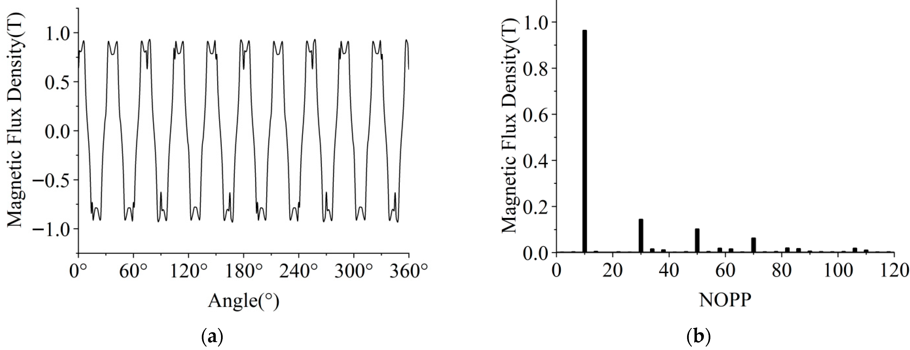
Under no-load conditions, the waveform and harmonic content of the radial air gap flux density directly affect the waveform and harmonic content of the back electromotive force of the motor. The radial air gap flux density waveform and spectrum of the coreless Halbach array permanent magnet motor under no-load conditions at a specific moment are shown in Figure 10.
It can be seen that the 3rd, 5th, and 7th harmonic contents of the radial air gap magnetic flux density of the Halbach array permanent magnet motor under no-load condition are relatively high, because the number of blocks per pole of the Halbach array is only 2 and the magnetization angle difference of each permanent magnet block is 90°. If the number of blocks per pole is continuously increased and the magnetization angle difference of each permanent magnet block is reduced, the air gap magnetic flux density will tend to be sinusoidal, but it will complicate the manufacturing process.
Although Figure 10 reflects the spatial distribution characteristics of the motor’s air gap magnetic flux density, it cannot reflect the variation of the air gap magnetic flux density with time. The obtained air gap magnetic flux density distribution is only the air gap magnetic flux density distribution at a specific pole slot relative position at a certain moment. In fact, since the relative positions of the magnetic poles and stator teeth are different at different times, the air gap magnetic field distribution will also be different.
To comprehensively analyze the variation of air gap magnetic flux density with time and space under the actual working conditions of the motor, this paper calculates the air gap magnetic field at different rotor positions within one electrical cycle. The spatio-temporal distributions of the radial and tangential component of the air gap magnetic flux density obtained are shown in Figure 11.
It can be seen from Figure 11 that within the 360° range of the air gap circumference, both the radial and tangential components of the air gap magnetic flux density have 10 periods, reflecting the fundamental magnetic field of the 24-slot 20-pole motor. Within 0.006 s, both the radial and tangential components of the air gap magnetic flux density have two half periods of positive and negative values, reflecting a complete electrical period of the motor. The maximum radial component of the air gap magnetic flux density is nearly 1 T, while the maximum tangential component is approximately 0.3 T and the waveform distortion is relatively large.
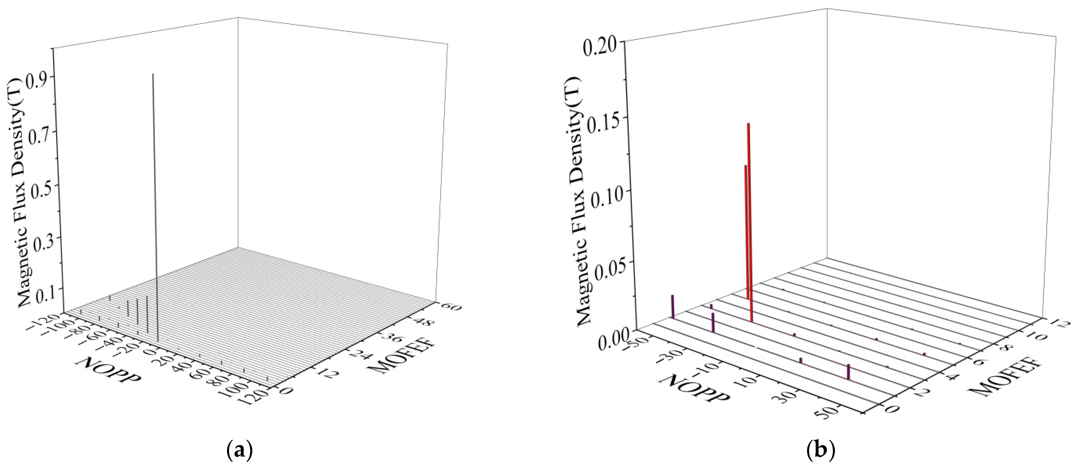
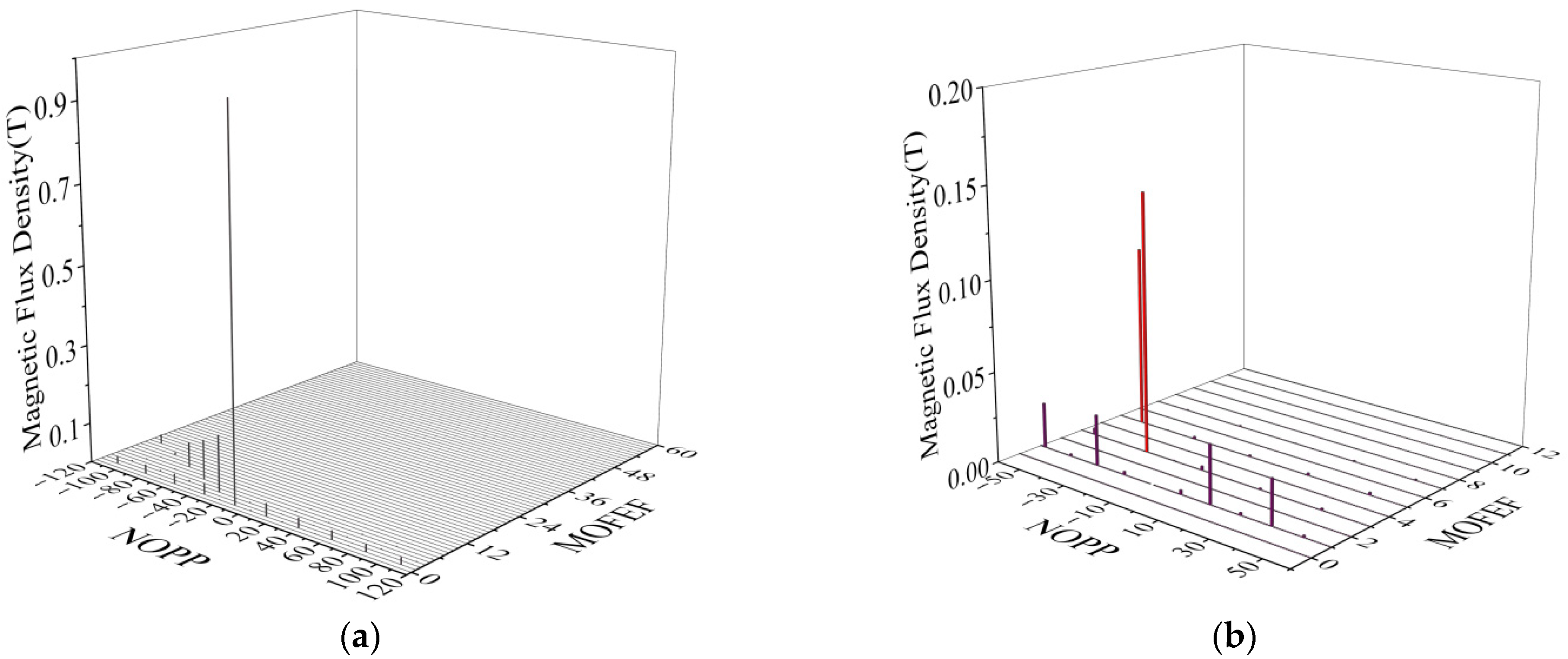
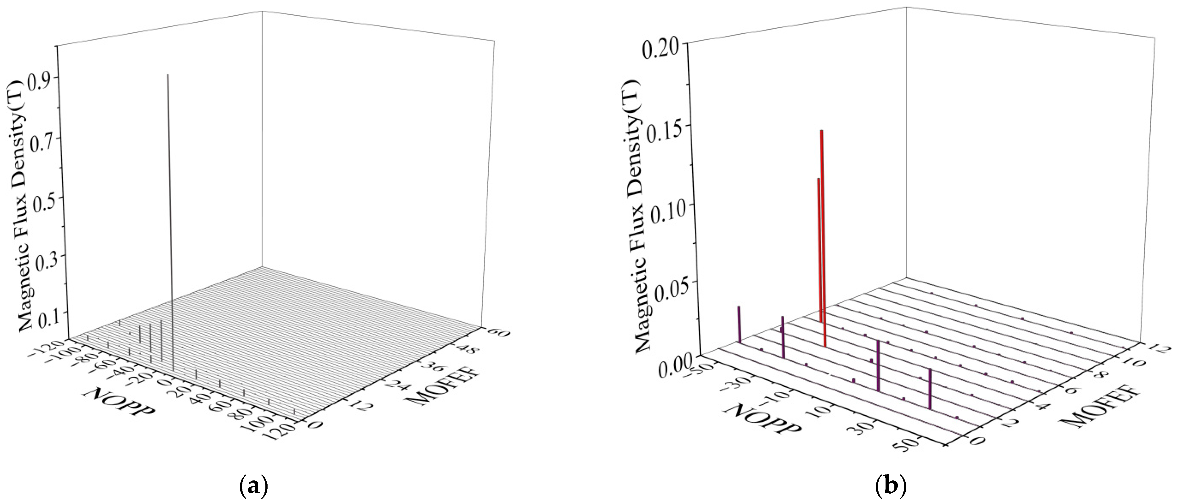
The spatio-temporal distribution diagrams of the radial and tangential components of the air gap magnetic flux density can only roughly determine the fundamental value of the radial component of the air gap magnetic flux density, which is not convenient for analyzing the harmonic values of the radial and tangential components of the air gap magnetic flux density, while the harmonic components of the air gap magnetic flux density are important factors causing the electromagnetic vibration of the motor. The harmonic amplitudes obtained by performing one-dimensional Fourier transform on the spatial distribution of the magnetic flux density at different moments are different and vary with time. The spatial harmonics with the same NOPP contain components of various rotational speeds. In this paper, the two-dimensional Fourier transform is performed on the spatio-temporal distribution of the radial and tangential components of the air gap magnetic flux density, and the spatio-temporal spectra obtained are shown in Figure 12 and Figure 13. In the figures, one fluctuation of the magnetic flux density distribution within a 360° circle in space is regarded as the magnetic flux density of one pair of poles in space. Figure 12b and Figure 13b are magnified partial views of Figure 12a and Figure 13a, respectively.
It can be seen from Figure 12a that the radial air gap magnetic flux density harmonics under no-load conditions are mainly related to the rotor magnetic poles (10 pairs), the NOPP of the harmonic magnetic flux densities is 2 k + 1 p (i.e., NOPP = 30 , 50 , 70 ), and the corresponding MOFEF is 2 k + 1 (i.e., MOFEF = 3 , 5 , 7 ), which is consistent with the theoretical analysis in the previous text. From Figure 12b, it can also be seen that the harmonic magnetic flux densities with NOPP = 14 , 34 , 38 , 58 , and MOFEF = 1 are generated by the interaction between the fundamental magnetomotive force of the magnetic pole ( NOPP = 10 ) and the fundamental and second-order harmonic air gap specific magnetic permeability ( NOPP = 24 , 48 ), which is consistent with the theoretical analysis in the previous text. Therefore, for the harmonic magnetic field under no-load conditions, the main magnetic field harmonic components should consider those generated by the interaction between the harmonic magnetomotive force of the magnetic pole and the constant air gap specific magnetic permeability, as well as the magnetic field components generated by the interaction between the fundamental magnetomotive force of the magnetic pole and the fundamental and second-order harmonic air gap specific magnetic permeability.
By comparing Figure 12 with Figure 13, it can be found that the NOPP and frequency components of the radial and tangential components of the air gap magnetic flux density under no load are exactly the same, verifying the analysis of the relationship between the radial and tangential magnetic flux density of the air gap in the previous text—that is, the tangential magnetic flux density harmonic always occurs along with the radial magnetic flux density harmonic, they have a phase difference of only 90°, but the NOPP and the MOFEF are the same. Furthermore, by comparing Figure 12a with Figure 13a, it can be found that the fundamental ( NOPP = 10 ) amplitudes of the radial and tangential components of the air gap magnetic flux density under no-load conditions differ significantly, approximately 10 times. By comparing Figure 11b with Figure 12b, it can be found that the harmonic amplitudes of the radial and tangential components of the air gap magnetic flux density under no-load conditions do not differ much.
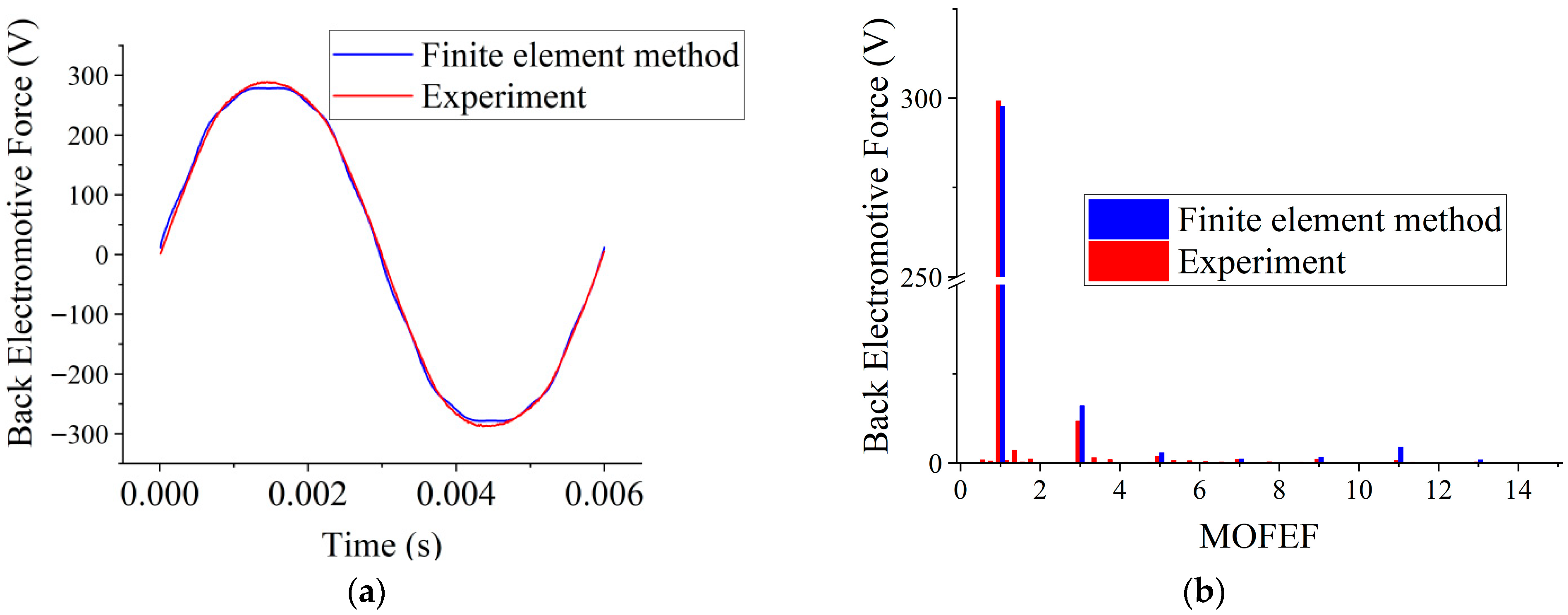
After obtaining the magnetic field distribution at different times based on the finite element method, the variation of the back electromotive force of the motor with time can be calculated from the difference quotient of phase flux linkage with respect to time. To verify the validity of the finite element method for calculating the electromagnetic field of the motor in this paper, an experiment was conducted on a 24-slot 20-pole rim-driven prototype. The comparison of the measured and finite element method-calculated back electromotive force is shown in Figure 14.
As can be seen from Figure 14, the overall agreement between the back electromotive force calculated by the finite element method and the measured one is relatively high, verifying the effectiveness of the finite element method used in this paper. Because the harmonic winding coefficient of the fractional slot concentrated winding motor is usually low, the back electromotive force harmonic content of the fractional slot concentrated winding motor is relatively low. It was also found that the amplitudes of the odd-order harmonics in the measured back electromotive force spectrum were lower than the finite element calculation results and there were fractional harmonics. This was mainly caused by the accumulation of installation tolerances of the permanent magnets in the actual manufacturing of the motor, which led to the offset of the magnetic poles and the non-completely symmetrical distribution of the rotor magnetic poles, as shown in Figure 15.
The electromagnetic air gap of the multi-pole fractional slot concentrated winding surface-mounted permanent magnet motor is relatively large. During motor manufacturing, the influence of rotor eccentricity and uneven air gap is relatively small. However, with a large number of magnetic pole blocks, it is easy to accumulate installation tolerances, resulting in fractional harmonics of magnetomotive force and back electromotive force. Attention should be paid during actual manufacturing.

4.2. Contains Only Fundamental Current

Under load conditions, the armature current has an impact on the air gap magnetic field. When only the fundamental current is considered, the spatio-temporal spectra of the radial and tangential components of the air gap magnetic flux density of the 24-slot 20-pole fractional slot concentrated winding coreless Halbach array permanent magnet motor in the rim-driven device are shown in Figure 16 and Figure 17.
It can be seen from Figure 16a that after considering the fundamental current, the change in the harmonic magnetic flux density generated by the magnetic poles with NOPP = 2 k + 1 p is not significant. However, the harmonic magnetic flux densities with NOPP = 14 , 34 , 38 , 58 , and MOFEF = 1 increase significantly. These harmonic components are the results of the interaction between the harmonic magnetomotive force with small NOPP and large amplitude generated by the armature of the 24-slot 20-pole motor in Figure 6 and the constant air gap specific magnetic permeability, verifying the theoretical analysis of the harmonic components of the air gap magnetic field considering the fundamental current in the previous text. Therefore, for the harmonic magnetic field generated by the fundamental current, the magnetic field component produced by the interaction between the harmonic magnetomotive force with a small NOPP and a large amplitude generated by the fundamental current and the constant air gap specific magnetic permeability should be mainly considered. Meanwhile, the comparison between Figure 16 and Figure 17 also verifies that the NOPP and the MOFEF of the tangential and radial air gap magnetic flux density harmonic under load conditions are exactly the same. Except for the fundamental amplitude, the harmonic amplitudes of the tangential magnetic flux density and the radial magnetic flux density do not differ much.

4.3. Contains Harmonic Currents

When the harmonic currents are considered, the spatio-temporal spectra of the radial and tangential components of the air gap magnetic flux density of the 24-slot 20-pole fractional slot concentrated winding coreless Halbach array permanent magnet motor of the rim-driven device are shown in Figure 18 and Figure 19, respectively.
After considering the harmonic current, no obvious difference is observed in the comparison between Figure 16a and Figure 18a. However, it can be seen from the comparison between Figure 16b and Figure 18b that the harmonic current did not introduce new harmonic components, but it increased the amplitudes of the magnetic flux densities with MOFEF = 3 , 5 , 7 , which have very small amplitudes when only considering the fundamental current. These components are mainly the result of the interaction between the harmonic magnetomotive force with relatively small NOPP generated by the harmonic current with MOFEF = 6 k ± 1 and the constant specific magnetic permeability, which is consistent with the theoretical analysis in the previous text. Therefore, for the harmonic magnetic field generated by the harmonic current of the motor, the magnetic field component produced by the interaction between the harmonic magnetomotive force with a small NOPP and a large amplitude generated by the harmonic current and the constant air gap specific magnetic permeability should be mainly considered. Other harmonic magnetic field components with smaller amplitudes can be disregarded. Meanwhile, the comparison between the radial magnetic flux density and the tangential magnetic flux density once again indicates that even when considering the harmonic current, the NOPP and the MOFEF of the tangential and radial air gap magnetic flux density harmonics under the load state are exactly the same, and the harmonic amplitudes of the tangential magnetic flux density and the radial magnetic flux density do not differ much.

5. Conclusions

For the thin-yoke wide-tooth fractional slot concentrated winding permanent magnet motor for RDDs, the following conclusion can be drawn:
For the harmonic magnetic field under no-load conditions, the main magnetic field harmonic components should consider those generated by the interaction between the harmonic magnetomotive force of the magnetic pole and the constant air gap specific magnetic permeability, as well as the magnetic field components generated by the interaction between the fundamental magnetomotive force of the magnetic pole and the fundamental and second-order harmonic air gap specific magnetic permeability.
For the harmonic magnetic field generated by the fundamental and harmonic currents of the motor, the magnetic field components produced by the interaction between the harmonic magnetomotive force with a small NOPP and a large amplitude generated by the fundamental and harmonic currents and the constant air gap specific magnetic permeability should be mainly considered. Other harmonic magnetic field components with smaller amplitudes can be disregarded.
The tangential magnetic flux density harmonic always occurs along with the radial magnetic flux density harmonic; they have the same NOPP and the MOFEF, the phase difference between them is 90°, and the amplitude difference between them is small.

Author Contributions

Conceptualization, C.J. and M.Q.; methodology, C.J., C.S. and M.Q.; software, C.J.; validation, C.J. and M.Q.; formal analysis, C.J. and C.S.; investigation, C.J.; resources, C.S.; data curation, C.J.; writing—original draft preparation, C.J.; writing—review and editing, C.J. and C.S.; visualization, C.S.; supervision, M.Q.; project administration, C.S.; funding acquisition, M.Q. All authors have read and agreed to the published version of the manuscript.

Funding

This research was supported by the National Natural Science Foundation of China (NSFC) (grant numbers 51877212).

Institutional Review Board Statement

Not applicable.

Informed Consent Statement

Not applicable.

Data Availability Statement

The data presented in this work are available upon request from the corresponding author.

Conflicts of Interest

The authors declare no conflicts of interest.

Abbreviations

The following abbreviations are used in this manuscript:
NOPPnumber of pole pairs
MOFEFmultiples of fundamental electrical frequency

References

  1. Dubas, A.J.; Bressloff, N.W.; Sharkh, S.M. Numerical modelling of rotor–stator interaction in rim driven thrusters. Ocean Eng. 2015, 106, 281–288. [Google Scholar] [CrossRef]
  2. Hassannia, A.; Darabi, A. Design and performance analysis of superconducting rim-driven synchronous motors for marine propulsion. IEEE Trans. Appl. Suppercon. 2014, 24, 5200207. [Google Scholar] [CrossRef]
  3. Tuohy, P.M.; Smith, A.C.; Husband, M.; Hopewell, P. Rim-drive marine thruster using a multiple-can induction motor. IET Electr. Power Appl. 2013, 7, 557–565. [Google Scholar] [CrossRef]
  4. Lai, S.H. Design Optimisation of a Slotless Brushless Permanent Magnet dc Motor with Helically-Wound Laminations for Underwater Rim-Driven Thrusters. Ph.D. Thesis, University of Southampton, Southampton, UK, 2006. [Google Scholar] [CrossRef]
  5. Piet, V.D. Manufacture of a Prototype Advanced Permanent Magnet Motor Pod. J. Ship Prod. 2003, 19, 91–97. [Google Scholar] [CrossRef]
  6. Liu, B.; Vanierschot, M.; Buysschaert, F. Numerical study of scale effects on the open water performance of a rim-driven thruster. Appl. Ocean Res. 2023, 138, 103667. [Google Scholar] [CrossRef]
  7. Liang, X.; Yan, X.; Ouyang, W.; Liu, Z. Experimental research on tribological and vibration performance of water-lubricated hydrodynamic thrust bearings used in marine shaft-less rim driven thrusters. Wear 2019, 426–427, 778–791. [Google Scholar] [CrossRef]
  8. Liang, J.; Zhang, X.; Qiao, M.; Zhu, P.; Cai, W.; Xia, Y.; Li, G. Optimal design and multifield coupling analysis of propelling motor used in a novel integrated motor propeller. IEEE Trans. Magn. 2013, 49, 5742–5748. [Google Scholar] [CrossRef]
  9. Yang, Z.; Yan, X.; Ouyang, W.; Bai, H.; Xiao, J. Multi-Parameter Fuzzy-Based Neural Network Sensorless PMSM Iterative Learning Control Algorithm for Vibration Suppression of Ship Rim-Driven Thruster. J. Mar. Sci. Eng. 2024, 12, 396. [Google Scholar] [CrossRef]
  10. Brown, D.W.; Repp, J.R.; Taylor, O.S. Submersible outboard electric motor/propulsor. Nav. Eng. J. 1989, 101, 44–52. [Google Scholar] [CrossRef]
  11. Richardson, K.M.; Pollock, C.; Flower, J.O. Design of a switched reluctance sector motor for an integrated motor/propeller unit. In Proceedings of the Seventh International Conference on Electrical Machines and Drives, Durham, UK, 11–13 September 1995; pp. 271–275. [Google Scholar] [CrossRef]
  12. Sharkh, S.M.A.; Lai, S.H.; Turnock, S.R. A structurally integrated brushless PM motor for miniature propeller thrusters. IEE Proc.-Electr. Power Appl. 2004, 151, 513–519. [Google Scholar] [CrossRef]
  13. Shen, Y.; Hu, P.; Jin, S.; Wei, Y.; Lan, R.; Zhuang, S.; Zhu, H.; Cheng, S.; Chen, J.; Wang, D.; et al. Design of novel shaftless pump-jet propulsor for multi-purpose long range and high speed autonomous underwater vehicle. IEEE Trans. Magn. 2016, 52, 7403304. [Google Scholar] [CrossRef]
  14. EL-Refaie, A.M. Fractional-Slot Concentrated-Windings Synchronous Permanent Magnet Machines: Opportunities and Challenges. IEEE Trans. Ind. Electron. 2009, 57, 107–121. [Google Scholar] [CrossRef]
  15. Chung, S.U.; Kim, J.M.; Koo, D.H.; Woo, B.C.; Hong, D.K.; Lee, J.Y. Fractional slot concentrated winding permanent magnet synchronous machine with consequent pole rotor for low speed direct drive. IEEE Trans. Magn. 2012, 48, 2965–2968. [Google Scholar] [CrossRef]
  16. Markovic, M.; Perriard, Y. Optimization Design of a Segmented Halbach Permanent-Magnet Motor Using an Analytical Mode. IEEE Trans. Magn. 2009, 45, 2955–2960. [Google Scholar] [CrossRef]
  17. Sadeghi, S.; Parsa, L. Multiobjective design optimization of five-phase halbach array permanent-magnet machine. IEEE Trans. Magn. 2011, 47, 1658–1666. [Google Scholar] [CrossRef]
  18. Wang, J.; Zhu, J. A simple method for performance prediction of permanent magnet eddy current couplings using a new magnetic equivalent circuit model. IEEE Trans. Ind. Electron. 2018, 65, 2487–2495. [Google Scholar] [CrossRef]
  19. Zhu, Z.Q.; Howe, D.; Bolte, E. Instantaneous magnetic field distribution in brushless permanent magnet DC motors. I. Open-circuit field. IEEE Trans. Magn. 1993, 29, 124–135. [Google Scholar] [CrossRef]
  20. Zhu, Z.Q.; Howe, D. Instantaneous magnetic field distribution in brushless permanent magnet DC motors. II. Armature-reaction field. IEEE Trans. Magn. 1993, 29, 136–142. [Google Scholar] [CrossRef]
  21. Zarko, D.; Ban, D.; Lipo, T.A. Analytical calculation of magnetic field distribution in the slotted air gap of a surface permanent-magnet motor using complex relative air gap permeance. IEEE Trans. Magn. 2006, 42, 1828–1837. [Google Scholar] [CrossRef]
  22. Li, J.; Choi, D.; Cho, Y. Analysis of rotor eccentricity in switched reluctance motor with parallel winding using fem. IEEE Trans. Magn. 2009, 45, 2851–2854. [Google Scholar] [CrossRef]
Figure 1. Impeller mechanical system: (a) hub-driven device (a three-dimensional model from the internet); (b) rim-driven device (a product of Schottel Company, Germany).
Applsci 15 11129 g001
Figure 2. Application of an RDD: (a) ship thrust propeller (a product of Brunvoll Company, Norway); (b) pipeline transfer pump (a three-dimensional model established by the author).
Applsci 15 11129 g002
Figure 3. Structure of RDD: (a) RDD with support shaft (a prototype made by Professor Sharkh from the University of Southampton); (b) RDD with no support shaft (a product of Vander Velden Marine System Company, The Netherlands).
Applsci 15 11129 g003
Figure 4. End winding of motor (physical objects from the internet): (a) common motor; (b) fractional slot concentrated winding motor.
Applsci 15 11129 g004
Figure 5. Fractional slot concentrated winding stator: (a) winding arrangement; (b) physical object.
Applsci 15 11129 g005
Figure 6. The per-unit value of the armature harmonic magnetomotive force of the 24-slot 20-pole fractional slot concentrated winding.
Applsci 15 11129 g006
Figure 7. Permanent magnet arrangement: (a) opposite polarity permanent magnets are alternately arranged (radially magnetized); (b) opposite polarity permanent magnets are alternately arranged (tangential magnetization); (c) Halbach permanent magnet array.
Applsci 15 11129 g007
Figure 8. Coreless Halbach permanent magnet array rotor: (a) arrangement of permanent magnets; (b) physical object.
Applsci 15 11129 g008
Figure 9. Magnetic field distribution of the permanent magnet motor for a rim-driven device: (a) magnetic field lines; (b) magnetic flux density.
Applsci 15 11129 g009
Figure 10. Radial air gap magnetic flux density under no-load conditions: (a) waveform; (b) spectrum.
Applsci 15 11129 g010
Figure 11. Spatio-temporal distribution of the air gap magnetic flux density under no-load conditions: (a) radial component; (b) tangential component.
Applsci 15 11129 g011
Figure 12. Spatio-temporal spectrum of radial magnetic flux density in air gap under no-load conditions: (a) complete; (b) partial.
Applsci 15 11129 g012
Figure 13. Spatio-temporal spectrum of tangential magnetic flux density in air gap under no-load conditions: (a) complete; (b) partial.
Applsci 15 11129 g013
Figure 14. Back electromotive force under no-load conditions: (a) waveform; (b) spectrum.
Applsci 15 11129 g014
Figure 15. Magnetic pole installation gap.
Applsci 15 11129 g015
Figure 16. Spatio-temporal spectrum of radial magnetic flux density in air gap with fundamental current: (a) complete; (b) partial.
Applsci 15 11129 g016
Figure 17. Spatio-temporal spectrum of tangential magnetic flux density in air gap with fundamental current: (a) complete; (b) partial.
Applsci 15 11129 g017
Figure 18. Spatio-temporal spectrum of radial magnetic flux density in air gap with fundamental and harmonic currents: (a) complete; (b) partial.
Applsci 15 11129 g018
Figure 19. Spatio-temporal spectrum of tangential magnetic flux density in air gap with fundamental and harmonic currents: (a) complete; (b) partial.
Applsci 15 11129 g019
Table 1. Design parameters of permanent magnet motor for an RDD.
Design ParameterValue (Unit)
Phase number3
Rated power11 kW
Rated (line) voltage380 V
Rated speed1000 r/min
Number of slots24
Number of poles20
Rated frequency166.67 Hz
Outer diameter of the stator core 350 mm
Inner diameter of the stator core 286 mm
Thickness of the stator epoxy resin sheath 1 mm
Physical air gap1 mm
Thickness of the stainless steel sheath of the rotor1 mm
Thickness of the permanent magnet12 mm
Flange thickness6 mm
Outer diameter of the impeller250 mm
Effective axial length56 mm
Table 2. Radial air gap magnetic flux density components under no-load conditions.
SourceNOPPMOFEF
Fundamental magnetomotive force of the magnetic pole and constant specific magnetic permeability p 1
Harmonic magnetomotive force of the magnetic pole
and constant specific magnetic permeability
μ μ / p
Fundamental magnetomotive force of the magnetic pole and fundamental specific magnetic permeability p ± N s 1
Harmonic magnetomotive force of the magnetic pole
and fundamental specific magnetic permeability
μ ± N s μ / p
Table 3. New radial air gap magnetic flux density components with fundamental current.
SourceNOPPMOFEF
Harmonic magnetomotive force of the armature with fundamental current and constant specific magnetic permeability ν 1
Harmonic magnetomotive force of the armature with fundamental current and fundamental specific magnetic permeability ν ± N s 1
Table 4. New radial air gap magnetic flux density components with harmonic current.
SourceNOPPMOFEF
Fundamental magnetomotive force of the armature with harmonic current and constant specific magnetic permeability p 6 k h ± 1
Harmonic magnetomotive force of the armature with harmonic current and constant specific magnetic permeability ν 6 k h ± 1
Fundamental magnetomotive force of the armature with harmonic current and fundamental specific magnetic permeability p ± N s 6 k h ± 1
Harmonic magnetomotive force of the armature with harmonic current and fundamental specific magnetic permeability ν ± N s 6 k h ± 1
Disclaimer/Publisher’s Note: The statements, opinions and data contained in all publications are solely those of the individual author(s) and contributor(s) and not of MDPI and/or the editor(s). MDPI and/or the editor(s) disclaim responsibility for any injury to people or property resulting from any ideas, methods, instructions or products referred to in the content.