Article

Numerical Investigation of the Bond–Slip Mechanism Between Deformed CFRP Bars and Ultra-High Performance Concrete

Key Laboratory of Intelligent Health Perception and Ecological Restoration of Rivers and Lakes, School of Civil Engineering, Architecture and Environment, Hubei University of Technology, Wuhan 430068, China
*
Author to whom correspondence should be addressed.
Appl. Sci. 2025, 15(20), 11066; https://doi.org/10.3390/app152011066
Submission received: 23 September 2025 / Revised: 8 October 2025 / Accepted: 13 October 2025 / Published: 15 October 2025

Abstract

To further investigate the bond behavior between carbon fiber-reinforced polymer (CFRP) bars and ultra-high-performance concrete (UHPC) under monotonic loading, a finite element model was established in ABAQUS based on existing experimental data. The material parameters, constitutive models, and interface contact definitions were verified through numerical simulation. Utilizing this modeling strategy, 36 center-pull finite element models with dimensions of 150 mm × 150 mm × 150 mm were analyzed. By systematically varying the geometric parameters of the CFRP bars, the effects of surface configuration, bar diameter, and rib spacing on the bond performance between CFRP bars and UHPC were analyzed. The results demonstrate that uniform-ribbed bars exhibit the highest bond performance, followed by helical-ribbed bars, whereas dented-ribbed bars show the lowest bond strength. The ultimate bond strength decreases with increasing bar diameter. For uniform-ribbed bars, the optimal rib spacing is 1.2D (where D is the bar diameter), resulting in the highest peak bond strength.

1. Introduction

Ultra-high-performance concrete (UHPC) is a cementitious composite material characterized by its exceptionally high compressive strength, high toughness, and superior durability. Its compressive strength typically exceeds 150 MPa, while the tensile strength is approximately 5 MPa [1,2,3,4,5]. Numerous studies have demonstrated that UHPC offers several advantages, including enhanced energy conservation and emission reduction, control and prevention of air pollution, enhanced construction quality, prolonged service life of structures, and strengthened disaster prevention and mitigation capabilities—all of which contribute to promoting the structural adjustment of the cement industry. Since its development, the application scope of UHPC has gradually expanded from bridge reinforcement, building restoration, and tunnel lining to serving as a primary load-bearing material. Carbon fiber-reinforced polymer (CFRP) bars, due to their low density, high specific strength, and high specific modulus [6,7,8,9], are a promising new material with broad application potential and can be effectively used in concrete structures such as slabs and short columns.
As two advanced materials, UHPC and CFRP bars exhibit distinct bond–slip behavior compared to conventional concrete and steel reinforcement [10]. The unique material properties of UHPC inevitably influence the bond performance between UHPC and CFRP bars. Therefore, it is essential to investigate the bond behavior between these two materials.
A substantial body of research has been conducted on UHPC and CFRP bars. Xie et al. [11] employed ABAQUS to investigate the influence of key parameters—including CFRP bar diameter, rib height, rib width, and concrete cover thickness—on bond performance under low-temperature conditions. Based on the simulation results, optimal bond behavior was achieved when the rib height was 8% D and the rib width was 2D. Ouyang et al. [12] conducted experimental studies on the bond performance between concrete and CFRP bars with four distinct surface morphologies. The results indicated that the bond performance, in ascending order, was: embossed bars < carbon strands < fine fiber-wound bars < coarse fiber-wound bars. Yoo et al. [6] investigated the bond strength between spiral-ribbed CFRP bars and UHPC and proposed a modified bond equation applicable to both spiral-ribbed and sand-coated CFRP bars. Chen et al. [13] conducted experimental research on the bond performance at the anchorage interface between CFRP bars and UHPC and proposed an optimal surface configuration for the bars. Ahmed et al. [14] investigated the bond behavior between concrete and basalt fiber-reinforced polymer (BFRP) bars with four different surface treatments and compared it to that of conventional steel bars. The results showed that BFRP bars exhibited lower bond stiffness but higher bond ductility, with a more gradual failure process. Jafari et al. [15] studied the influence of bond strength between steel reinforcement and low-strength concrete (LSC) on reinforced concrete structures, and using the LASSO optimization algorithm, a closed-form solution was developed to predict bond strength, integrating key influencing parameters. Shahmansouri et al. [16] developed a machine learning prediction model based on a Multi-Layer Perceptron (MLP) network to evaluate the bond–slip behavior in CFRP-confined low-strength concrete. This machine learning model has been established as a quantitative and reliable tool for predicting the bond–slip characteristics of CFRP-confined low-strength concrete, providing a practical solution for strengthening vulnerable structures.
The number of specimens is limited, data dispersion is relatively high, and only one variable is usually taken into account per test. Traditional experimental methods make it challenging to measure the stress state at different locations within the interface, mainly because UHPC fully encloses CFRP bars. These are some of the limitations that still exist in current studies. Therefore, to create a high-precision model, numerical simulation is required. In this study, a three-dimensional (3D) improved model that captured the rib geometric properties of CFRP bars was constructed using the finite element program ABAQUS. The model was validated against experimental results, confirming its accuracy. The bond–slip behavior between UHPC and ribbed CFRP bars with various surface morphologies was then examined using numerical simulations. The bond–slip curve, bond stress distribution, and the underlying bond mechanism between the two materials were given special attention. The results indicate that the interfacial bond strength and ductility can be significantly improved by appropriately reducing the bar diameter, optimizing surface morphology, and adjusting rib spacing.

2. Materials and Methods

2.1. Bond–Slip Tests

A very intricate bond–slip interaction occurs at the interface between the deformed steel bars and the surrounding concrete in reinforced concrete. According to mechanical transfer theory, this interaction is precisely what allows steel bars and concrete to effectively transmit stress, resulting in coordinated deformation under loading and, ultimately, a stable load-bearing capacity for the entire structural system. The term “bond” refers to this contract. Three main elements comprise the bond force between steel and concrete: frictional resistance, chemical adhesion, and mechanical interlock between the steel ribs and concrete. In particular, chemical adhesion and frictional resistance provide the majority of the bond force between plain steel bars and concrete, while mechanical interlock between the steel ribs and concrete principally controls the bond force between ribbed steel bars and concrete.
To obtain the nonlinear bond stress–slip curve, extensive research has been conducted by scholars both domestically and internationally. Currently, three primary experimental methods are widely adopted:
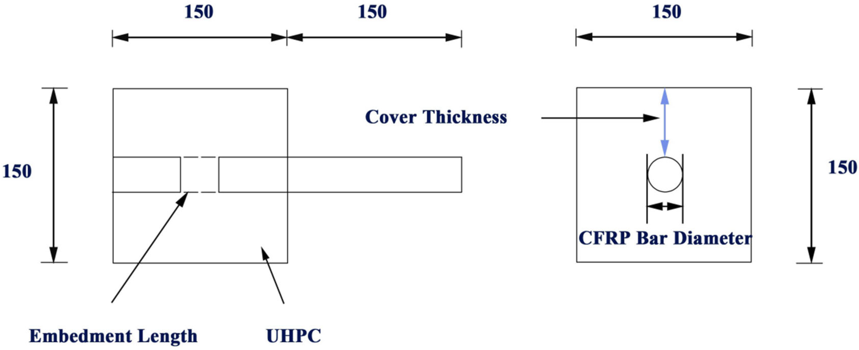
  • Center-pull test: As a recommended method specified in the Standard for Test Methods of Concrete Structures (GB50152–92) [17], the center-pull test is also the most widely used experimental approach. Specimens are typically prismatic or cylindrical in shape, with the steel bar positioned at the geometric center of the specimen. The casting process is performed horizontally, and the bond length is controlled by encasing the steel bar in PVC sleeves. This method is characterized by operational simplicity and facilitated data analysis, thereby being widely employed in contemporary bond–slip research.
  • Beam Tests: Beam tests (as shown in Figure 1) are categorized into full-beam tests and half-beam tests. Specifically, the full-beam test investigates the bond behavior between reinforcing bars and concrete through the bending of supported beams. Compared with the central pull-out test, this method can more accurately reflect the actual stress states of reinforcing bars and concrete in practical engineering scenarios. Nevertheless, its application remains limited, primarily due to the complexity of specimen fabrication and the high associated costs. The half-beam test offers relatively simplified specimen fabrication. It not only allows for the adjustment of the bending moment-to-shear force ratio but also enables the application of “dowel force”, making it a commonly used method for determining the development length of reinforcing bars. However, the presence of size effects may lead to discrepancies in strength and crack width between the scaled-down model and the prototype, as the material properties of the scaled model may not be consistent with those of the original.
3.
Axial Tension Test: The axial tension test is primarily employed to characterize the bond behavior across cracks and the evolution of cracking. In this test, the reinforcing bar is subjected to pure tensile loading; however, this loading condition does not replicate the stress states experienced by reinforcing bars under complex loading scenarios in practical engineering. Furthermore, the test typically quantifies global slip, making it challenging to capture local slip at the interface between the reinforcing bar and the concrete.
In summary, the central pull-out test demonstrates notable advantages: it enables accurate quantification of stress distribution and relative slip, while also facilitating straightforward data processing and analysis.

2.2. Finite Element Model for Bond–Slip

The bond–slip behavior between UHPC and ribbed CFRP bars with various surface morphologies was then examined using numerical simulations (as shown in Figure 2). Special attention was paid to the bond–slip curve, bond stress distribution, and the underlying bonding mechanism between the two materials. Finally, the findings demonstrate that the interfacial bond strength and ductility of CFRP bars can be effectively enhanced by reducing the bar diameter appropriately, optimizing the surface morphology, and refining the rib spacing.

3. Finite Element Model

3.1. Geometric Model

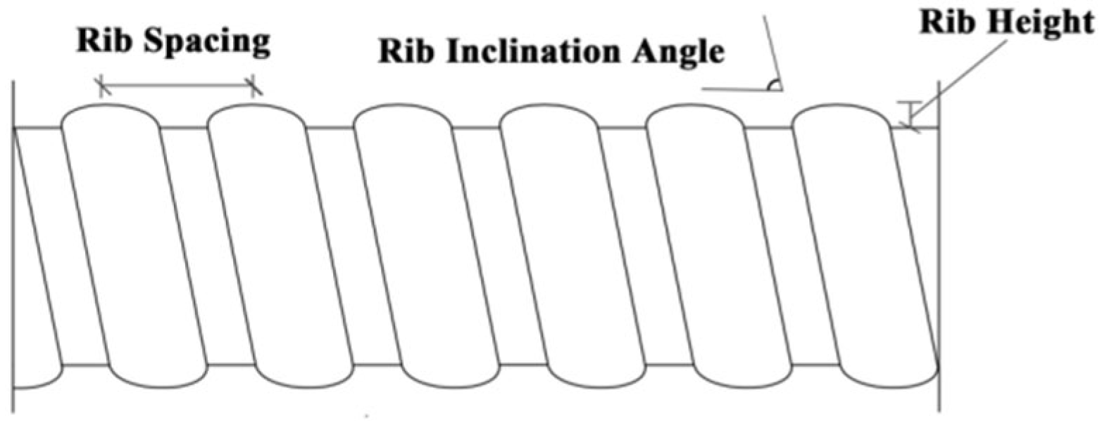
The schematic diagram illustrating the rib parameters of ribbed CFRP bars is presented in Figure 3. Among these parameters, the rib spacing of the bar is defined as the axial center-to-center distance between two adjacent ribs on the surface of the ribbed bar, while the rib inclination angle refers to the angle formed between the ribs on the surface of the ribbed bar and the bar axis.
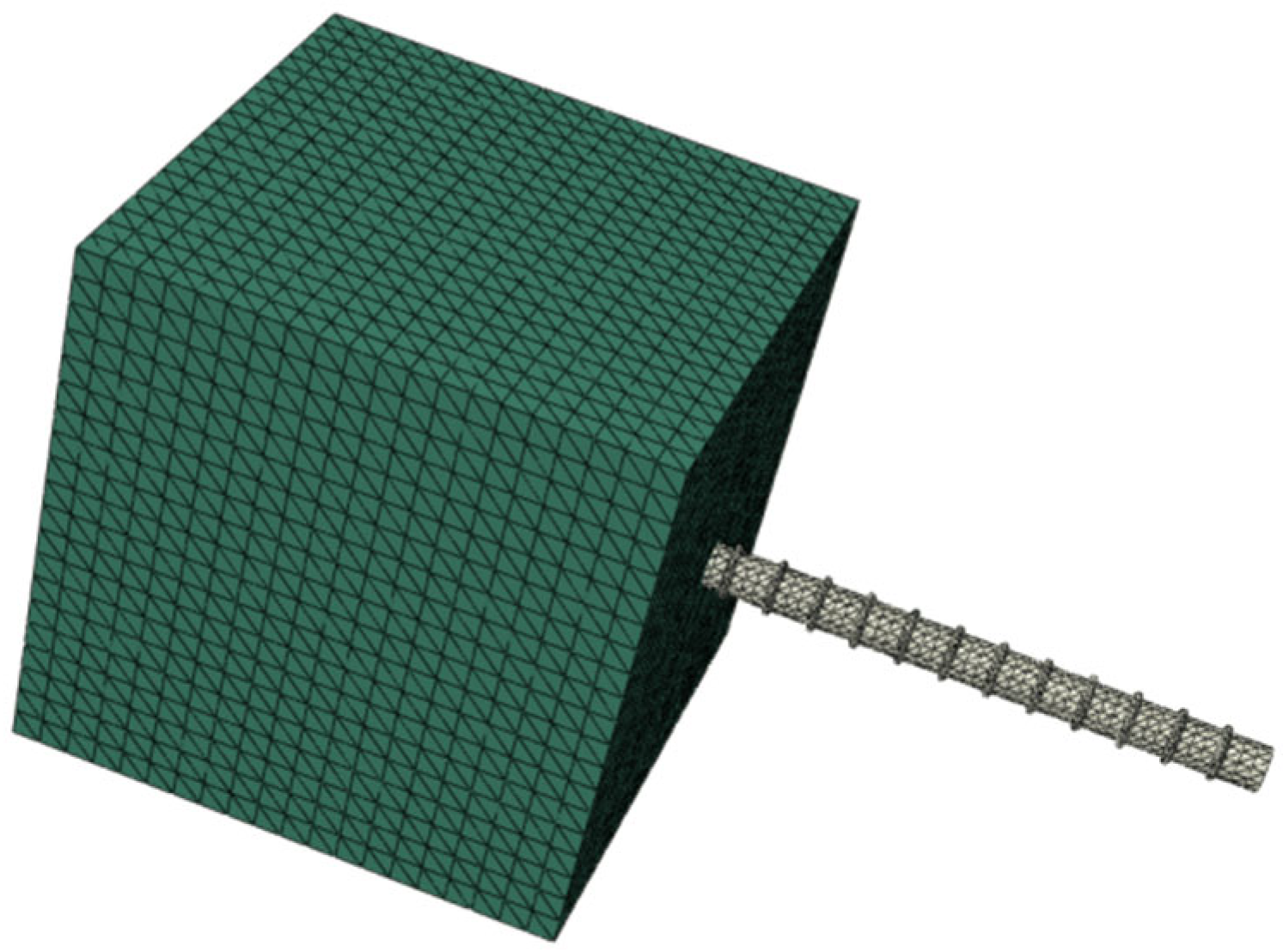
In the present study, both UHPC and CFRP bars were modeled using continuous solid elements, with the element type specified as C3D10. This element is a 3D 10-node tetrahedral element with integrated mid-side nodes, enabling more accurate simulation of complex geometric configurations and deformation behaviors. Notably, it is particularly suitable for high-precision nonlinear analyses, such as contact analysis and large-deformation problems.
To balance computational efficiency and analysis accuracy, a mesh convergence analysis was performed, and the element type parameters were optimized accordingly. The results indicated that the optimal mesh size for UHPC was 8 mm, whereas the optimal mesh size for CFRP bars was 4 mm (as shown in Figure 4).

3.2. Constitutive Relations

ABAQUS offers three types of constitutive models for concrete: the diffuse cracking model, the brittle cracking model, and the plastic damage model. Specifically, the diffuse cracking model “diffuses” concrete cracks throughout the entire element, treating concrete as an anisotropic material. It characterizes the effects of crack initiation by modifying the constitutive relationship of the concrete material [18]. In contrast, the brittle cracking model cannot adequately simulate the crack propagation process under coarse meshes; thus, it is generally applicable to plain concrete or scenarios involving minimal reinforcement.
The plastic damage model assumes that concrete primarily undergoes tensile cracking and compressive failure. Specifically, it characterizes the inelastic behavior of concrete by integrating isotropic elastic damage with isotropic tensile and compressive plasticity theories of tensile and compressive plasticity. This model can effectively simulate the mechanical responses of concrete subjected to monotonic, cyclic, or dynamic loading under low confining pressures, while maintaining excellent numerical convergence. Therefore, the concrete damaged plasticity (CDP) model was adopted as the material model for UHPC.
To fully define the concrete damaged plasticity model in ABAQUS, the following five key parameters require specification, with their respective values and justifications detailed as follows:
  • Dilatation angle: Set to 30°.
  • Eccentricity of the flow potential: This parameter characterizes the deviation between the plastic flow potential function and the hyperbolic asymptote; its value was specified as 0.1 in this study.
  • Biaxial compressive strength ratio (fb0/fc0): This ratio reflects the strength degradation behavior of the material under multiaxial stress states. Based on the strength criterion established by Chiew et al. [19] through classical biaxial compression tests, it was set to 1.16.
  • Parameter k: This parameter represents the ratio of the second invariant of stress on the tensile and compressive meridians at the initial yielding stage, and characterizes the relative position of the tension–compression meridians on the π-plane. By integrating the elastoplastic theoretical framework proposed by Sarikaya [20] and the numerical validation results from Kmiecik [21], a value of 2/3 was adopted as its characteristic parameter.
  • Viscosity parameter (μ): This parameter governs the convergence stability of the viscoplastic regularization process. To satisfy the computational accuracy requirements for quasi-static analysis, it was set to 0.0001.
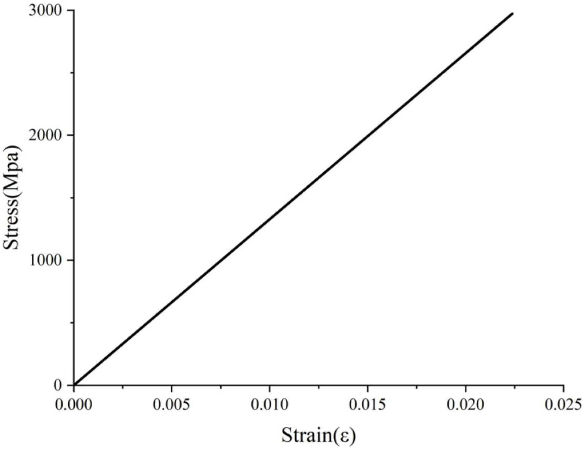
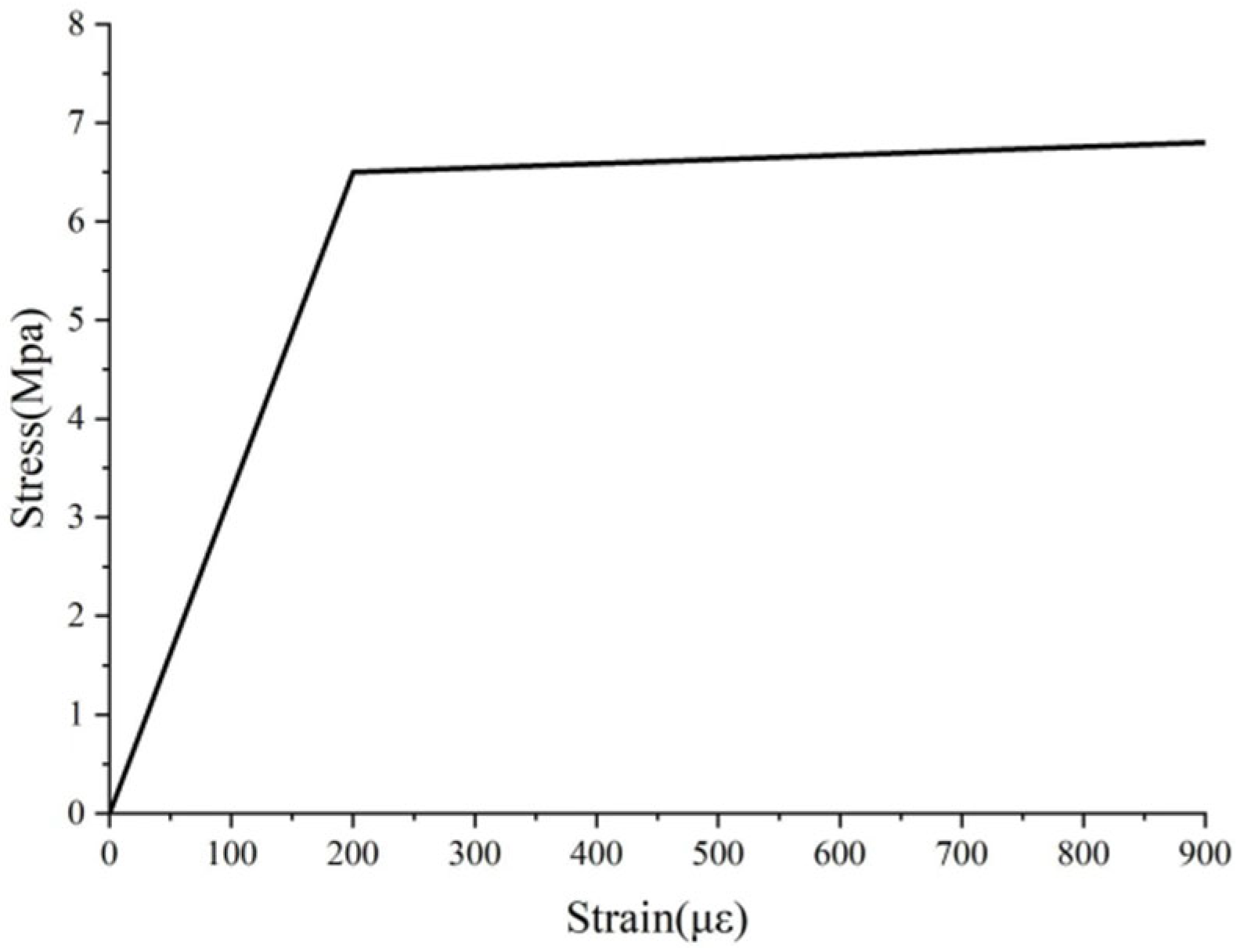
The stress–strain relationship of CFRP bars was simplified to that of an ideal linear elastic material, with the hardening phase neglected. The basic parameters are specified as follows: density = 1600 kg/m3, elastic modulus = 230 GPa, and Poisson’s ratio = 0.2. Since the bars did not reach yielding during the finite element simulation, the strain rate effect of the bars was not considered, and the stress–strain curve of CFRP bars exhibited a linear relationship [22], as shown in Figure 5. However, it should be noted that CFRP bars are heterogeneous and anisotropic materials [23]. To simulate this material characteristic of CFRP, the “HASHIN DAMAGE” model in ABAQUS was employed—this model is specifically developed to simulate the brittle failure behavior of materials post-fracture.
The constitutive relations of UHPC were defined by adopting two distinct relationships: the tensile stress–strain relationship proposed by Shan Bo [24], and the compressive stress–strain relationship proposed by Zhang Zhe [25]. Specifically, based on the compressive stress–strain relationship developed by Shan Bo, the expression for the uniaxial compressive stress–strain curve of UHPC is given as follows:
y = A x + 6 5 A x 5 + 4 A 5 x 6 0 x 1     x a x - 1 2 + x   x 1
where y = εc0—here, εc denotes the instantaneous compressive strain of UHPC at any loading stage, and ε0 represents the peak compressive strain of UHPC; x = σc/fc, where σc refers to the compressive stress of UHPC, and fc denotes the axial compressive strength of UHPC prisms; α is the descending parameter of the constitutive curve, with a specified value of 2.41; parameter A is defined as the ratio of the tangent elastic modulus E0 at the origin of the stress–strain curve to the secant modulus (Ep) at the peak point [26].
The expression of the stress–strain curve of UHPC under uniaxial tension is as follows:
y = f c t ε c a ε 0 ε ε c a f c t ε c a ε ε p c
The uniaxial compressive stress–strain relationship curve and uniaxial tensile stress–strain relationship curve of the UHPC constitutive model are presented in Figure 6 and Figure 7, respectively.

3.3. Contact Conditions

In the finite element software ABAQUS, several commonly used approaches are available for simulating the contact behavior between steel bars and concrete.
Reinforcing bars were modeled using truss elements. During meshing, a one-to-one correspondence between the nodes of reinforcing bars and concrete was enforced, with Spring2 elements incorporated at these nodal points. Given that the built-in linear springs in ABAQUS cannot effectively simulate bond–slip behavior, modifications to nonlinear springs were implemented in the input file. This approach is both simple and effective; however, its accuracy is highly dependent on the spring parameters typically derived from bond–slip constitutive models obtained through experimental tests. Furthermore, this method is more suitable for plain steel bars and does not apply to ribbed bars with varied surface configurations.
Cohesive bond elements were incorporated at the interface between concrete and reinforcing bars. The application of cohesive bond elements necessitates the simulation of complex damage evolution processes, which in turn requires refined meshing to accurately capture the mechanical behavior of the bond interface. Owing to the substantial computational resources consumed by this approach and its high demands on computer performance, it was not adopted in the present study.
Within the interaction module of the finite element software ABAQUS, the surface-to-surface contact algorithm was adopted. In the contact property settings, the tangential and normal contact behaviors were explicitly defined, and the penalty contact method was employed for contact calculation. This approach enables an in-depth investigation of the effects of various surface geometric parameters of reinforcing bars on the bond–slip behavior between reinforcing bars and concrete.
Existing studies have demonstrated that the bond force between ribbed CFRP bars and the UHPC matrix can be decomposed into three components: chemical adhesion, mechanical interlocking, and interfacial friction. Among these, chemical adhesion contributes merely 5–8% of the total bond strength, and its effect is limited to the initial stage of interfacial relative slip. Given its negligible influence on the overall interfacial mechanical behavior, chemical adhesion was excluded from the present analysis. Instead, this study considers only interfacial friction and mechanical interlocking, employing the surface-to-surface contact method to simulate the bond–slip behavior between CFRP bars and UHPC.
In the normal direction, a hard contact condition was adopted, ensuring no mutual penetration between contact surfaces during regular pressure transfer. In the tangential direction, the friction coefficient (μ) at the interface between CFRP bars and UHPC was set to 0.3 [27].

3.4. Validation of the Finite Element Model for Bond–Slip Between CFRP Bars and UHPC

In this section, the central pull-out test of UHPC and CFRP bars as cited in Reference [28] was selected as the validation object. A corresponding finite element model was established using ABAQUS, and comparative analyses were performed on key metrics including the bond–slip curve, peak bond strength during the bond–slip process, and the slip value corresponding to the peak bond strength was compared and analyzed. This validation confirms the effectiveness and accuracy of the proposed modeling approach in ABAQUS, thereby providing a methodological basis for subsequent simulations.
The loading protocol for the pull-out test in the referenced study employed load-controlled loading, and the same loading method was adopted in the finite element simulation. From the finite element analysis results, the force-displacement curve was extracted for subsequent analysis. Existing research has demonstrated that when the anchorage length of CFRP bars is relatively short, the interfacial bond stress can be approximately uniformly distributed along the axial direction of the bars. Notably, the bond stress in this context refers to the shear stress acting at the interface between the reinforcing bars and concrete [29]. Based on this theoretical assumption, the average bond stress is typically defined as the bond strength. The formula for calculating the bond strength between CFRP bars and UHPC is given as follows:
τ = P π d l d
  • τ—bond strength (MPa);
  • P—axial tensile force (kN);
  • d—diameter of CFRP bars (mm);
  • ld—anchorage length of CFRP bars (mm).
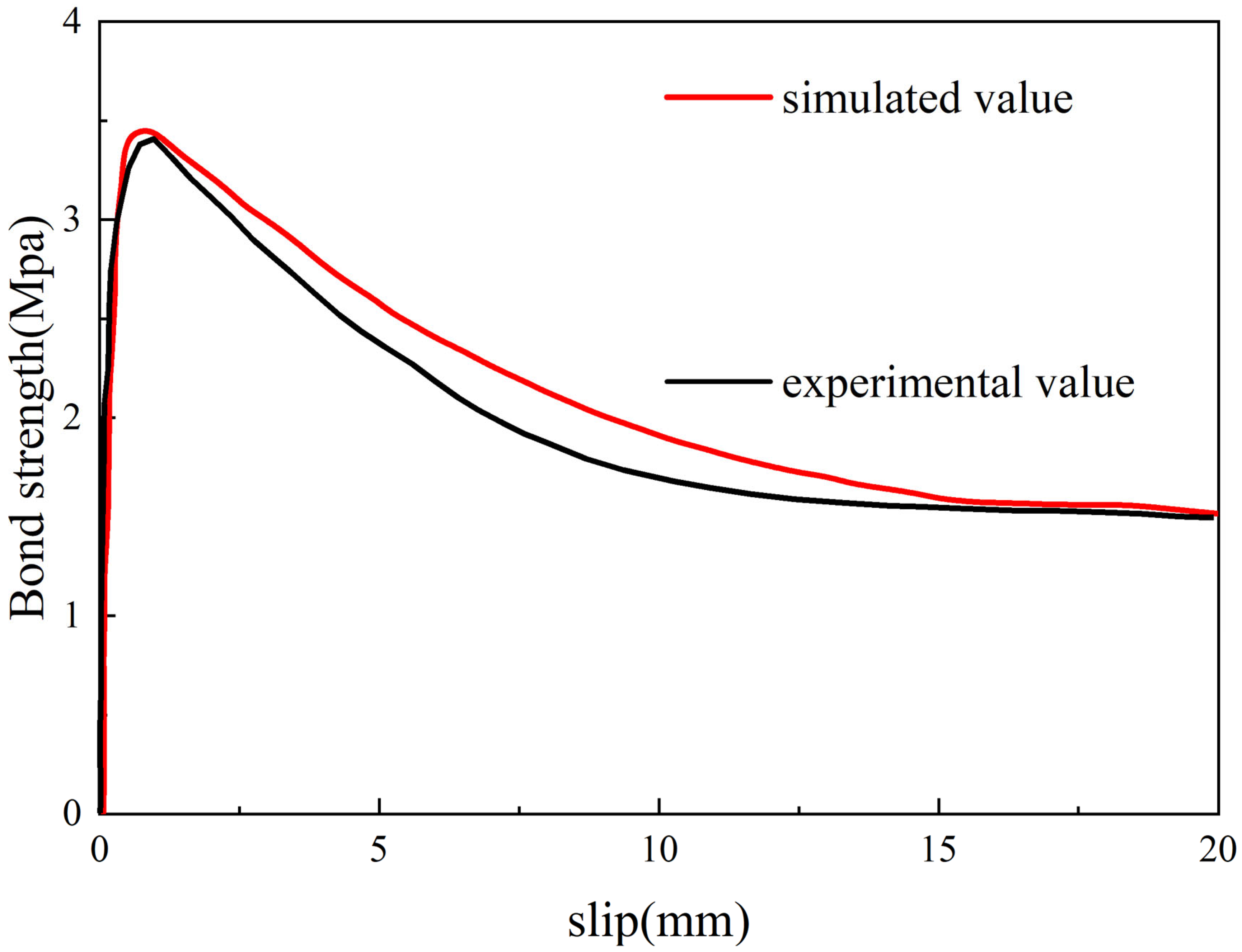
A comparison between the experimental results (from the pull-out test) and the finite element simulation results is presented in Figure 8.
As observed from Figure 8, the experimental values and simulated values exhibit good consistency in both the peak stress phase and the residual phase, whereas a certain degree of deviation is observed in the ascending phase. This discrepancy is primarily attributed to the omission of the effect of chemical adhesion during the modeling process. A comparison between the simulated bond–slip curve and the experimental curve reveals a relatively high overall fitting degree between the two. Furthermore, the errors in key characteristic parameters—including peak bond strength and peak bond slip—are negligible.
Based on the aforementioned analysis, the numerical simulation results demonstrate a high degree of agreement with the experimental data. Consequently, ABAQUS can be reliably employed to investigate the bond–slip behavior between CFRP bars and UHPC, as the simulation exhibits minimal errors and favorable predictive performance (as shown in Table 1).

4. Bond–Slip Performance of CFRP Bars and UHPC

4.1. Influencing Factors

Multiple factors, including bar diameter, surface morphology, rib spacing, cover thickness, bar embedment depth, and UHPC compressive strength, among others, influence the bond–slip performance of CFRP bars embedded in UHPC. For the present study, the effects of the following three factors on the bond behavior between CFRP bars and UHPC were selected for investigation:
Reinforcing bars with three distinct surface morphologies were adopted, namely crescent-ribbed reinforcing bars, helical-ribbed reinforcing bars, and equal-height-ribbed reinforcing bars.
Three distinct bar diameters were selected for analysis, namely 12 mm, 14 mm, and 16 mm.
Four distinct rib spacings were selected for investigation, namely 9.6 mm, 12 mm, 14.4 mm, and 19.2 mm.
A total of thirty-six (3 × 3 × 4) finite element models were established and analyzed using ABAQUS. The model designation consists of four components, with specific coding rules as follows:
“C” denotes carbon fiber-reinforced polymer bars;
“L”, “Y”, and “X” represent helical-ribbed bars, crescent-ribbed bars, and equal-height-ribbed bars, respectively;
The numerical value following “D” indicates the bar diameter;
The numerical value following “B” specifies the spacing between adjacent ribs of the bar.
For instance, the model labeled “C-LD12-B14.4” corresponds to a pull-out test specimen featuring helical-ribbed CFRP bars with a diameter of 12 mm and a rib spacing of 14.4 mm.

4.2. Effect of Bar Surface Morphology

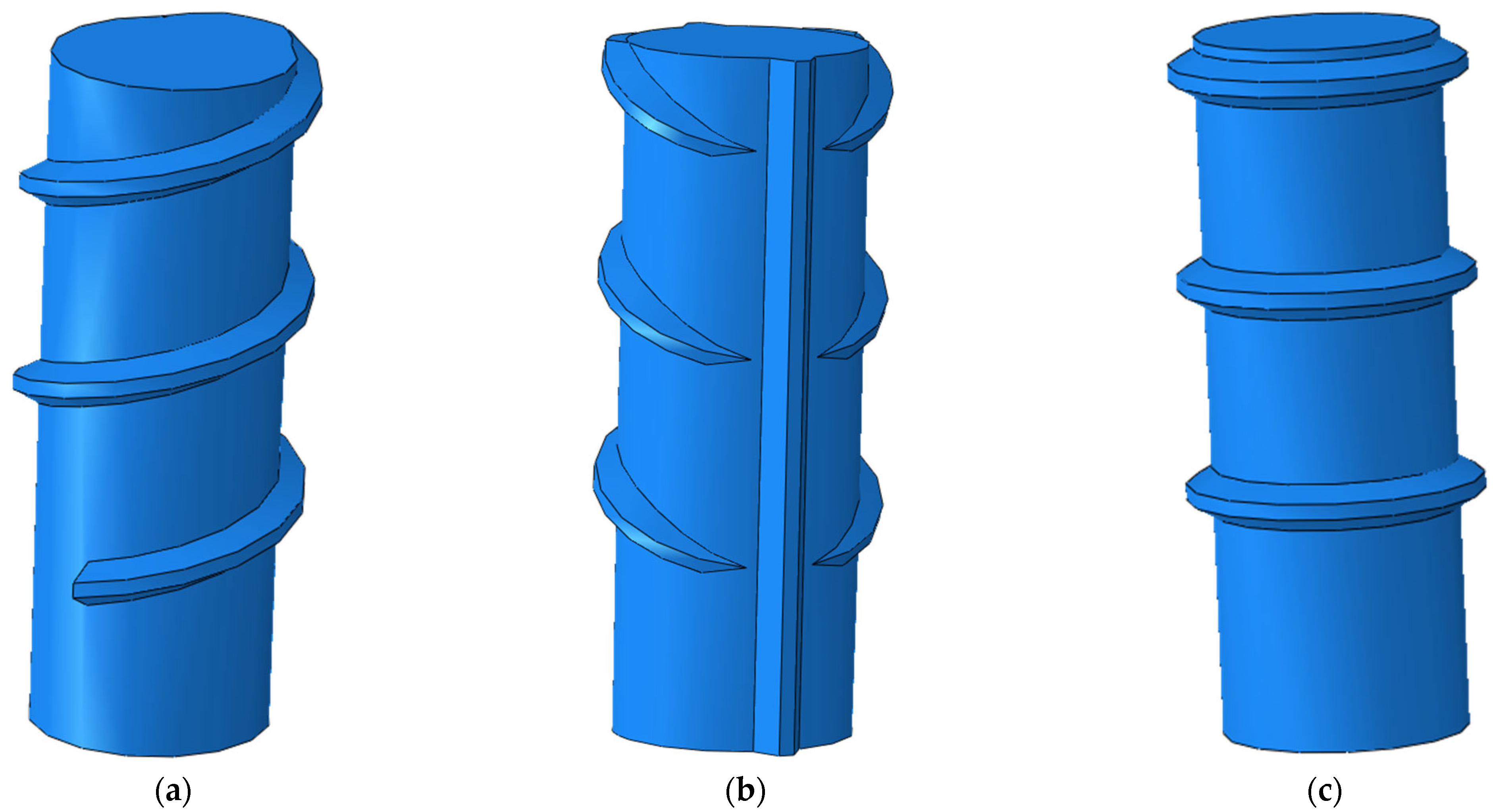
In this section, three types of CFRP bars with distinct surface morphologies were considered, namely helical-ribbed bars, crescent-ribbed bars, and equal-height-ribbed bars (see Figure 9). The crescent-ribbed bars featured a rib inclination angle of 60°, whereas the equal-height-ribbed bars had a rib inclination angle of 90°. All CFRP bars shared identical transverse rib dimensions: a rib height of 1.5 mm and a rib width of 2.6 mm.
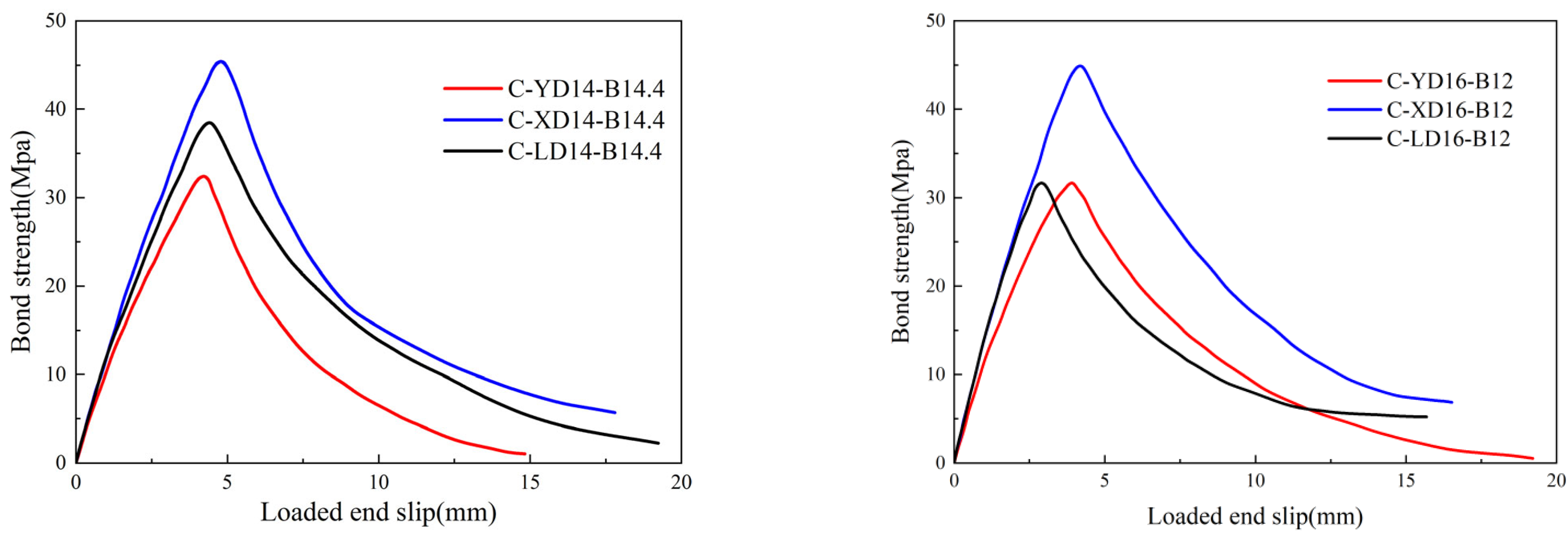
To determine the optimal geometric configuration of CFRP bars, this section strictly controlled the effects of geometric parameters on interfacial performance and eliminated the influence of the geometric size effect on bond performance. Results analysis was conducted on crescent-ribbed bars, equal-height-ribbed bars, and helical-ribbed bars—under two sets of parameter combinations: (1) bar diameter = 16 mm and rib spacing = 12 mm; (2) bar diameter = 14 mm and rib spacing = 14.4 mm.
As observed from Figure 10, the bond–slip curves of CFRP bars with distinct surface morphologies exhibit significant discrepancies. Both the bond strength and residual bond strength follow the same descending order: equal-height-ribbed bars > helical-ribbed bars > crescent-ribbed bars.
Under the parameter combination of 16 mm diameter and 12 mm rib spacing, the bond strength of equal-height-ribbed CFRP bars was 45.9% and 41.8% higher than that of crescent-ribbed and helical-ribbed CFRP bars, respectively. For the combination of 14 mm diameter and 14.4 mm rib spacing, the bond strength of equal-height-ribbed bars exceeded that of crescent-ribbed and helical-ribbed bars by 40.6% and 17.3%, respectively. This superiority arises from the annular closed-protrusion structure of the ribs in equal-height-ribbed bars; this distinctive surface geometric feature enables more efficient transfer of interfacial shear stress, thereby significantly enhancing bond performance. In contrast, the inclined rib tips of crescent-ribbed and helical-ribbed bars are more susceptible to inducing stress concentration and shear failure, ultimately resulting in localized concrete cracking. Analysis of the residual bond phase reveals that the residual bond strength of equal-height-ribbed bars accounts for approximately 20% of the peak bond strength, which is superior to that of the other two bar types.

4.3. Effect of CFRP Bar Diameter

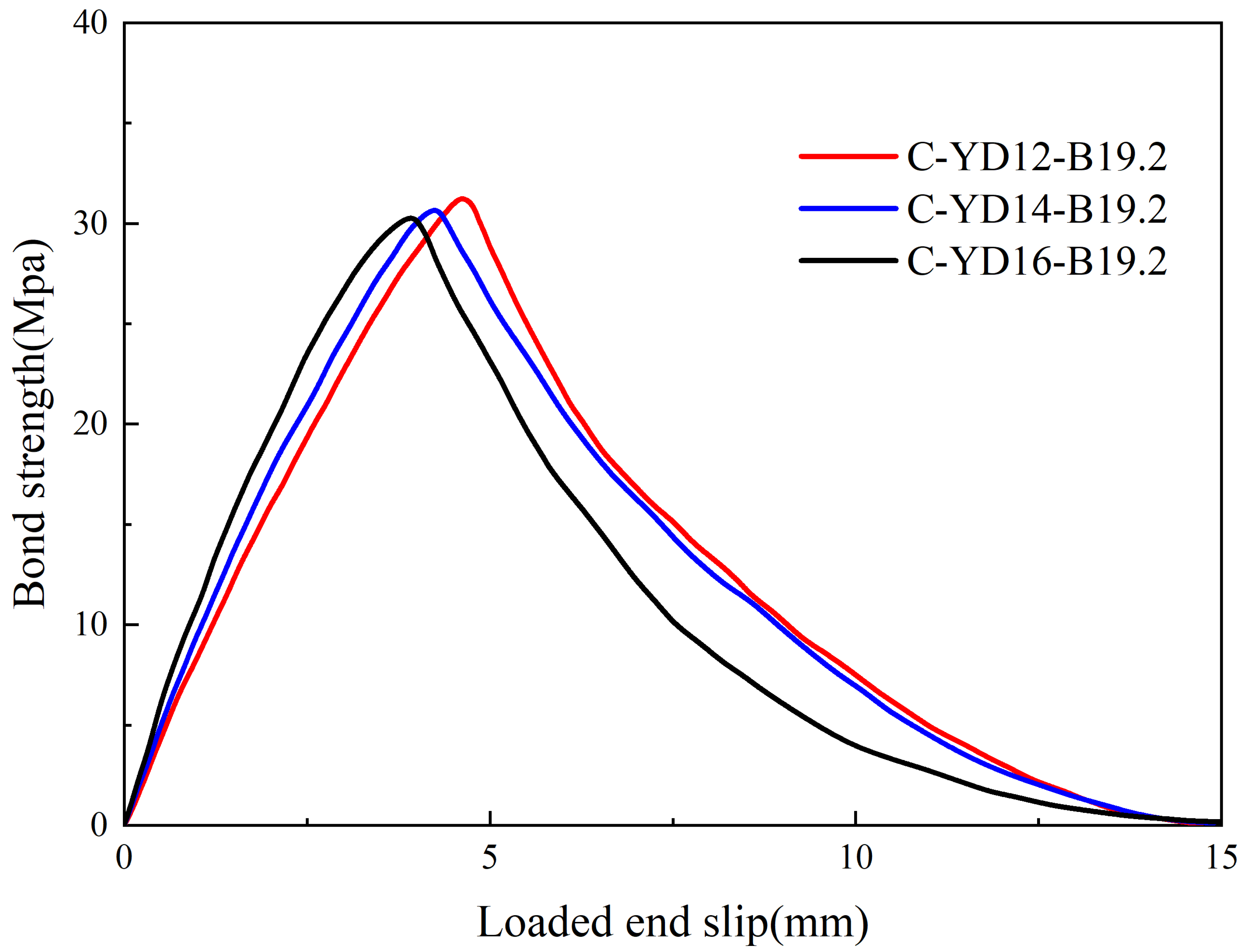
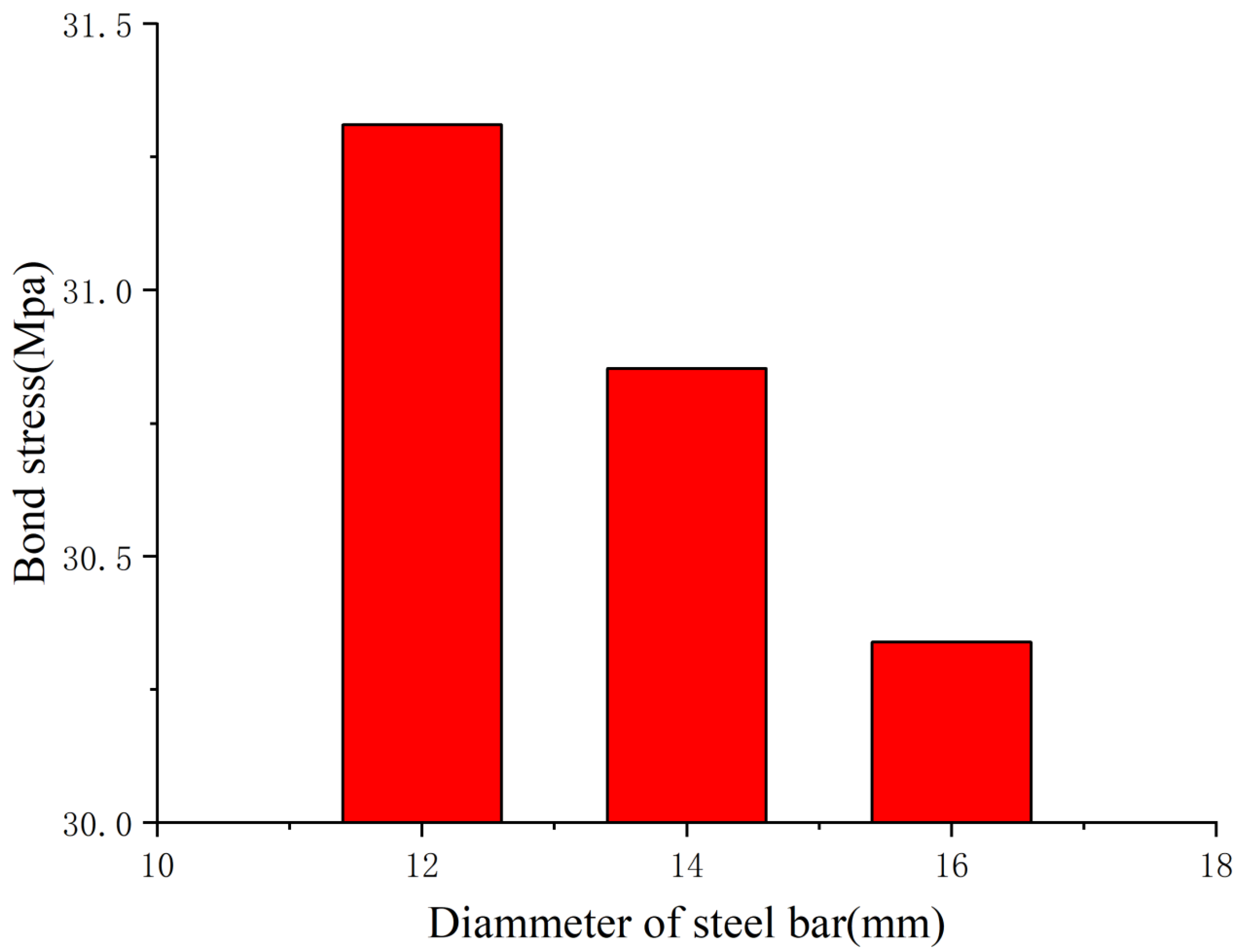
In this section, three distinct diameters of CFRP bars were considered, namely 12 mm, 14 mm, and 16 mm. Taking crescent-ribbed CFRP bars as an example, Figure 11 and Figure 12 illustrate that the bar diameter exerts a relatively minor influence on the bond strength of these bars. Furthermore, as the diameter of crescent-ribbed bars increases, the bond strength exhibits a decreasing trend.
The primary mechanism underlying this phenomenon is the Poisson effect. Under identical stress conditions, as the diameter of CFRP bars increases, their radial contraction effect becomes more pronounced, thereby diminishing the interfacial bond behavior between CFRP bars and UHPC. Additionally, the relatively low shear stiffness of CFRP bars exerts a significant influence on their bond performance. For a fixed anchorage length, the bond stress of CFRP bars exhibits greater sensitivity to diameter variations. Owing to the shear lag effect, non-uniform deformation arises between the central and surface regions of the cross-section when CFRP bars are subjected to tensile loading. This deformation discrepancy induces a non-uniform distribution of everyday stress across the cross-section, further impairing the interfacial bond performance. Another key factor is that as the diameter of CFRP bars increases, despite the constant rib height, the rib height-to-diameter ratio gradually decreases, resulting in reduced surface roughness of the bars. This reduction in surface roughness weakens the enhancement of bond strength, such that the beneficial effect on bond performance diminishes with increasing diameter.

4.4. Effect of Rib Spacing

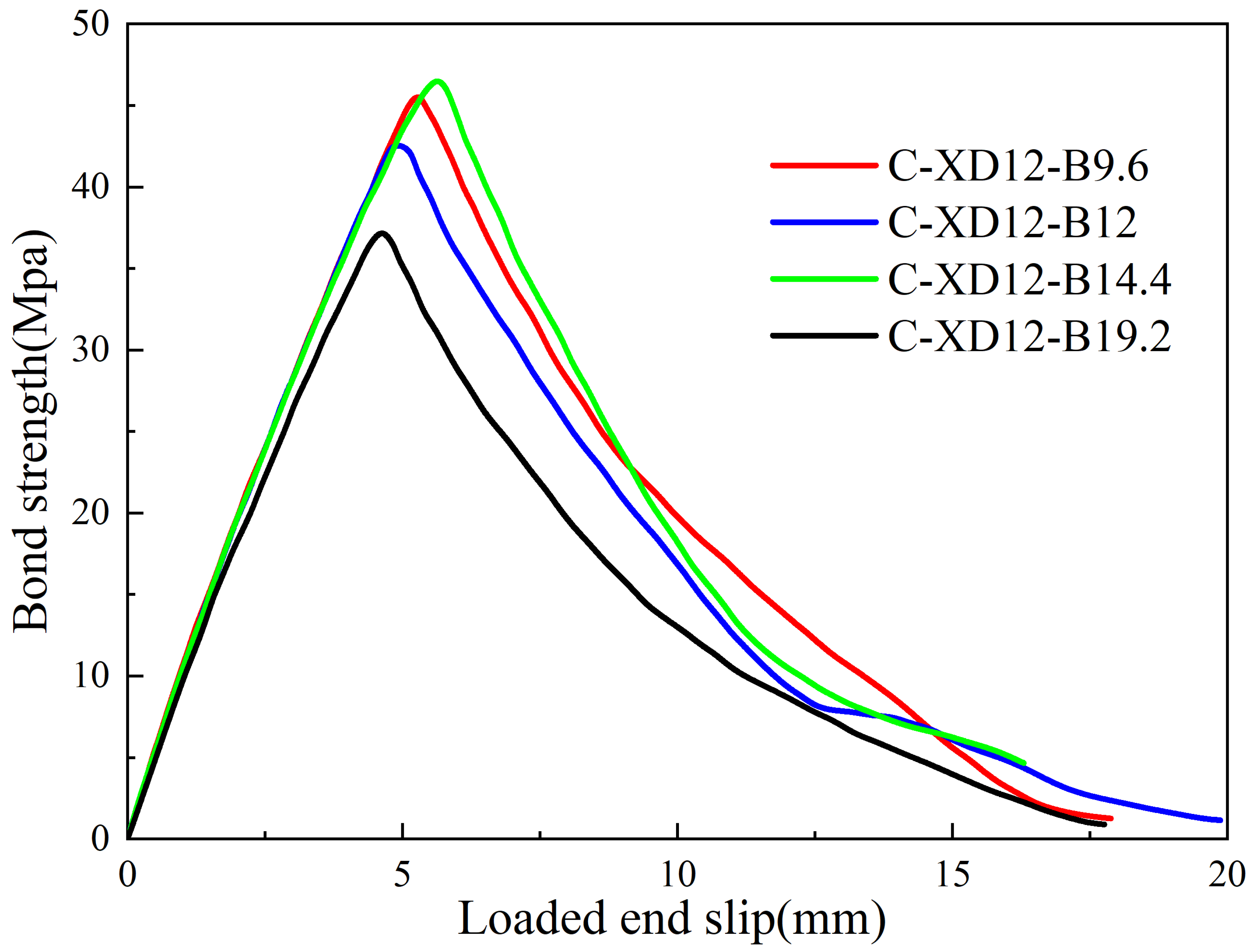
In this section, CFRP bars with a fixed diameter of 12 mm and four distinct rib spacings were analyzed. The distances between adjacent ribs are 9.6 mm, 12 mm, 14.4 mm, and 19.2 mm, corresponding to 0.8D, 1.0D, 1.2D, and 1.6D. A comparison of the bond–slip curves reveals that the bond–slip performance and overall ductility between CFRP bars and UHPC are optimal when the rib spacing is 14.4 mm (as shown in Figure 13). Specifically, the peak slip and peak bond strength are minimized at a rib spacing of 1.6D, whereas they reach their maximum values at a rib spacing of 1.2D.
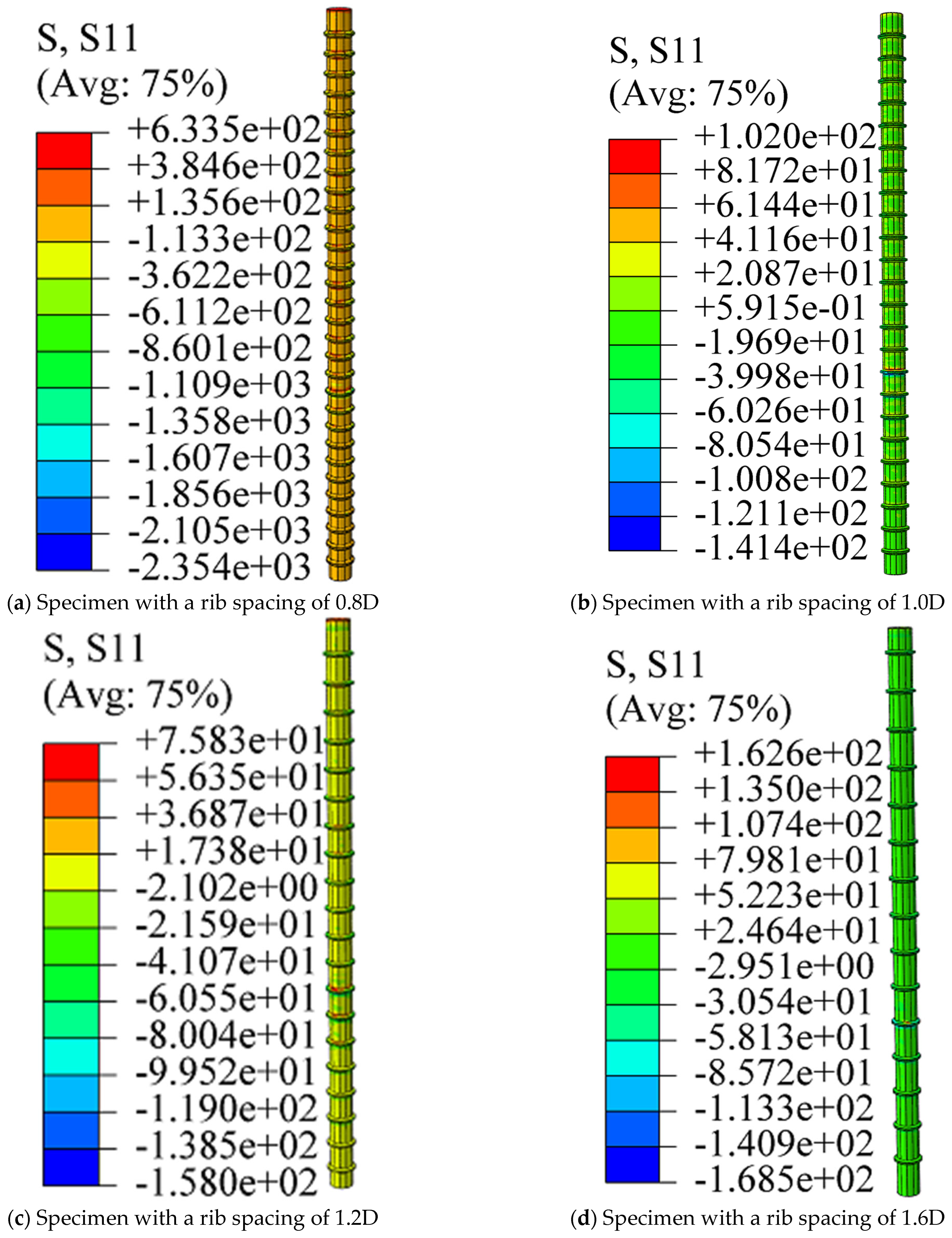
It can be observed from the stress contour plots in Figure 14 and Figure 15 that for specimens with rib spacings of 0.8D, 1.0D, 1.2D, and 1.6D, when the peak bond stress is reached, neither the axial tensile stress nor the shear stress of the bars reaches the strength limit. This indicates that the failure mode of the specimens is mainly caused by tensile damage to the concrete.
As illustrated in Figure 14, stress concentration tends to occur near the loading end of the CFRP bars. For specimens with small rib spacings, the stress magnitude range is relatively large, rendering the specimens susceptible to failure due to local overloading. As the rib spacing increases from 0.8D to 1.2D, the stress distribution gradually becomes uniform—this indicates more coordinated stress transfer between the CFRP bars and the UHPC matrix under this rib spacing range.
A further observation reveals that when the rib spacing is 1.6D, although the overall stress distribution is relatively uniform, the considerable inter-rib distance reduces the effective bond area. This, in turn, leads to the rapid development of interfacial slip and a subsequent decrease in peak bond stress.
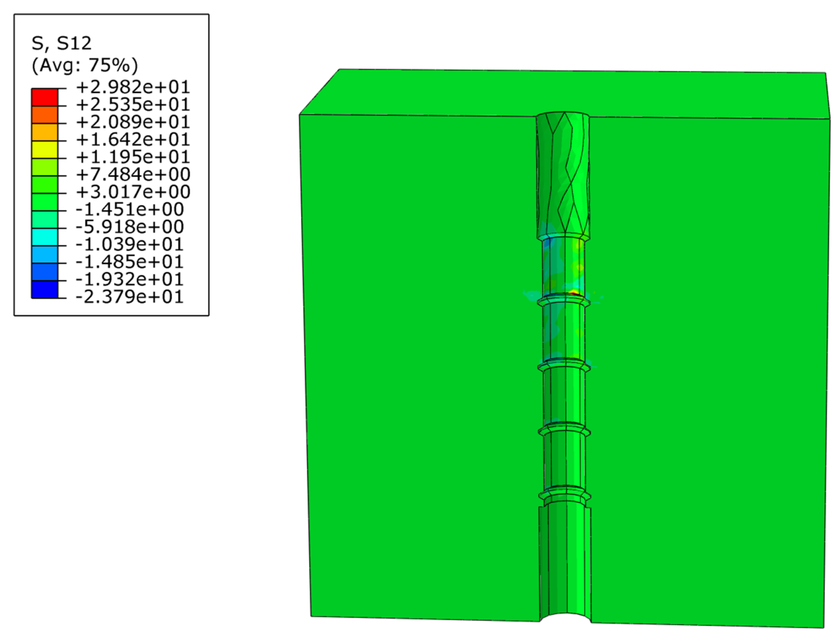
Figure 15 presents the axial shear stress contour plots of CFRP bars with varying rib spacings. As illustrated in the figure, the UHPC matrix damage zone is primarily concentrated around the ribs of the CFRP bars, with no penetrating cracks observed. When this observation is compared with the characteristic of microcracks initiating in the UHPC matrix at the loading end (as shown in Figure 19), it further confirms that the dominant failure mode of the specimens is the UHPC matrix tensile damage—rather than CFRP bar fracture or interfacial debonding.
When the rib spacing is small, the volume of the UHPC matrix between adjacent ribs decreases, which weakens the mechanical interlocking force between the UHPC and CFRP bars. During the pull-out process, the UHPC matrix between the ribs is prone to shear stress concentration, resulting in premature shear failure. This failure mechanism ultimately leads to the pull-out of CFRP bars from the UHPC matrix.
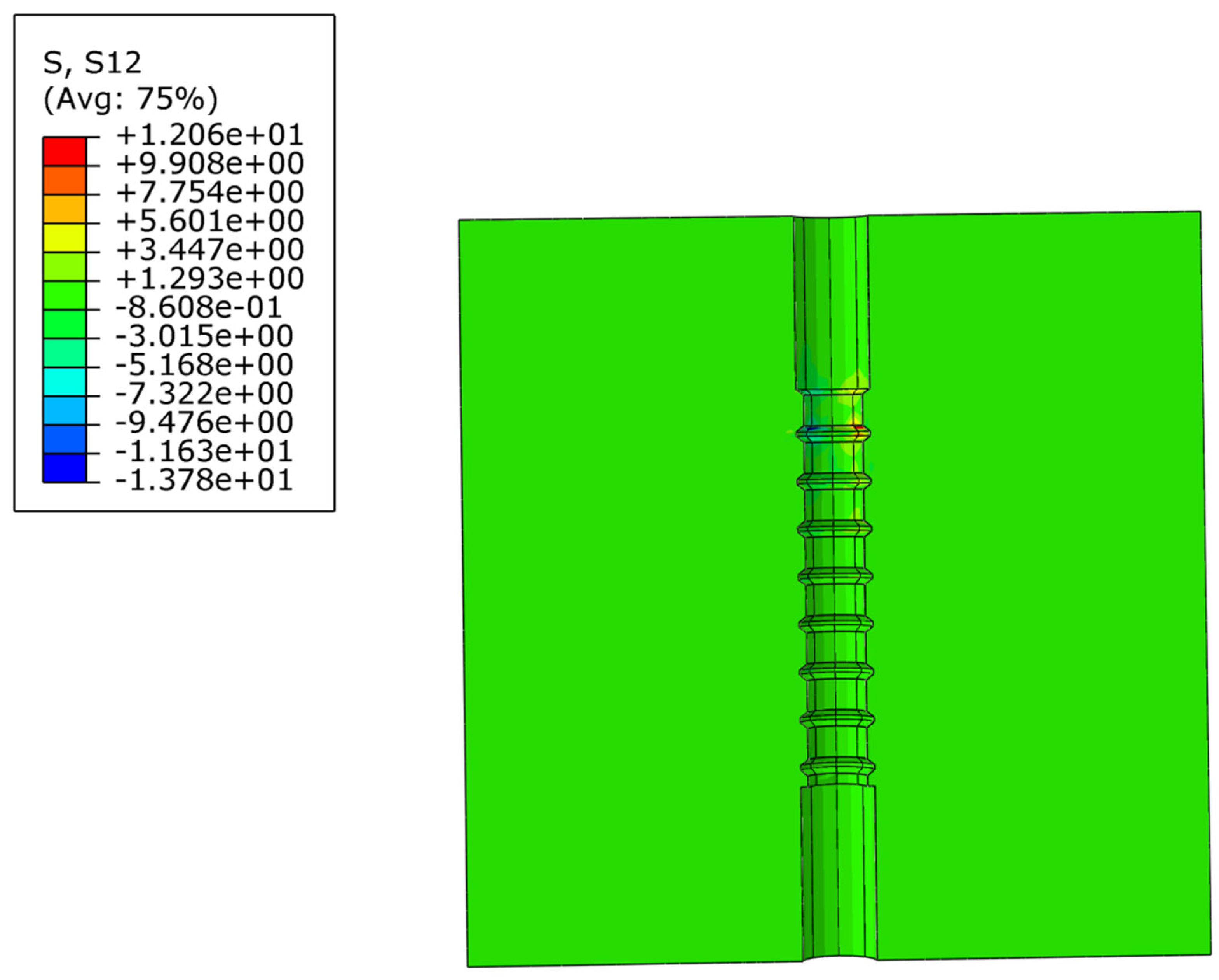
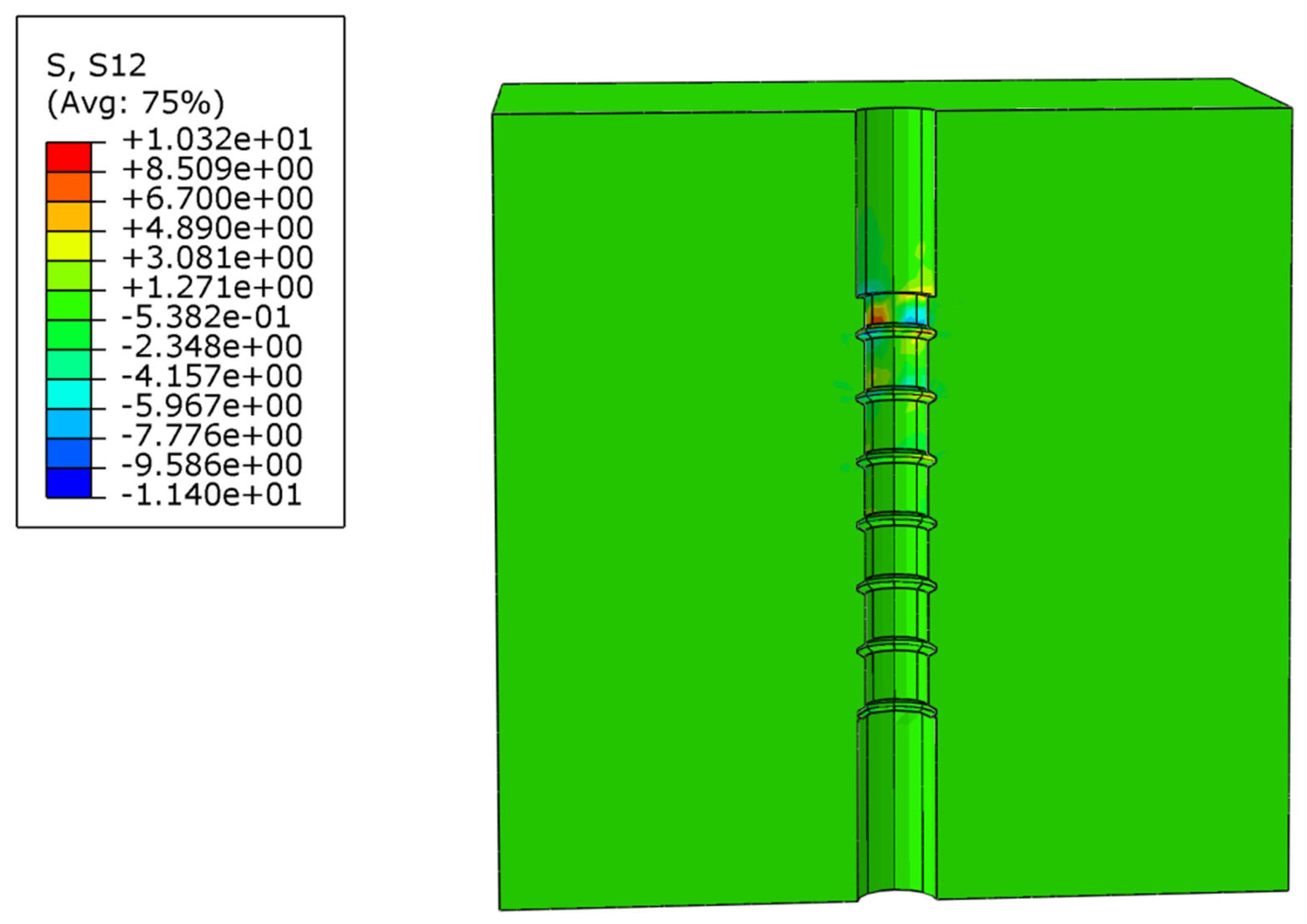
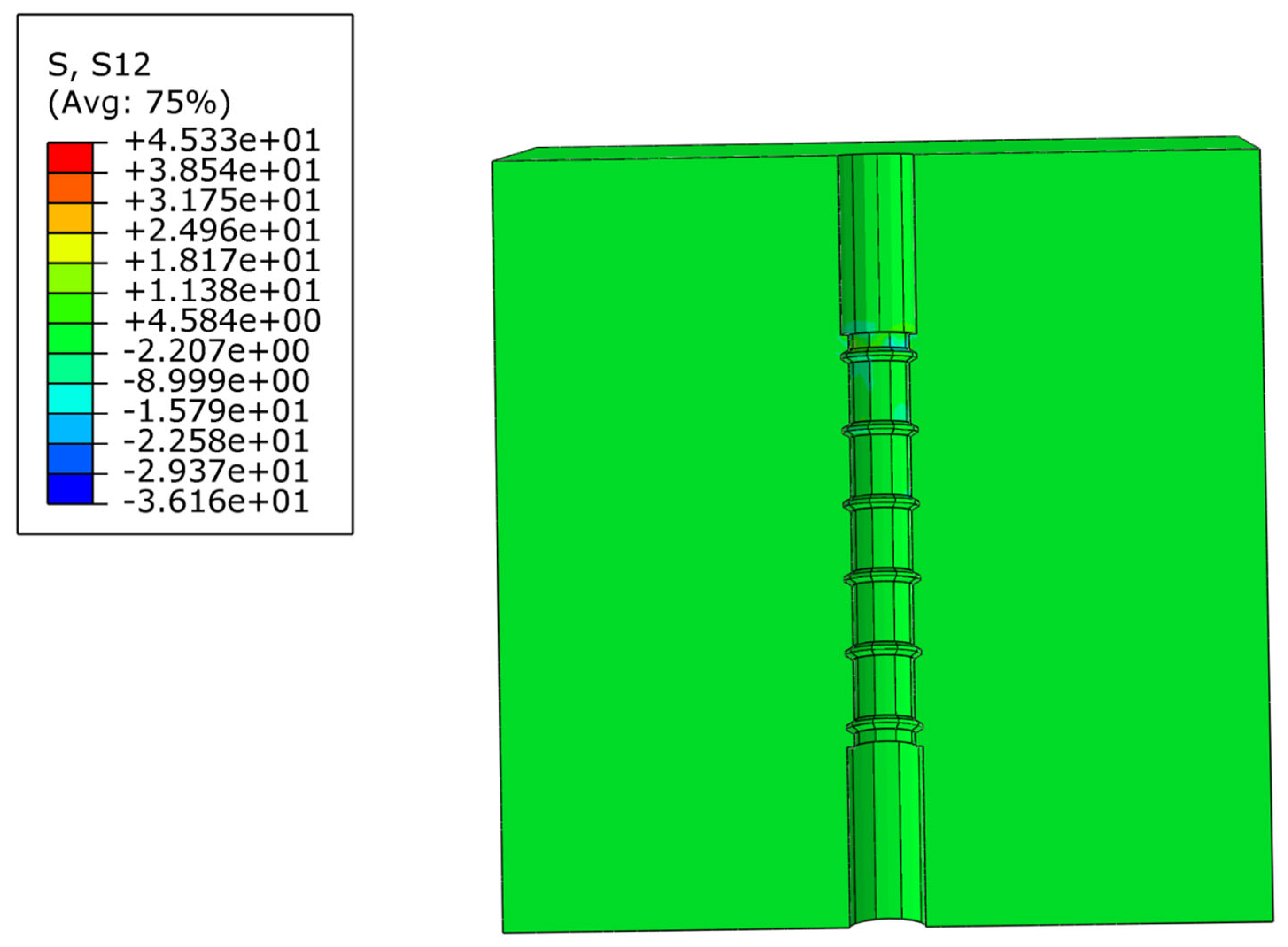
The shear stress distribution can be intuitively observed from Figure 16, Figure 17, Figure 18 and Figure 19. Owing to the ribbed surface of the CFRP bars, the stress distribution within the surrounding UHPC matrix is non-uniform. The results indicate that as the slip magnitude increases, the stress of the CFRP bars at different positions along the anchorage length gradually increases, with stress levels being higher near the loading end.
On the other hand, when the rib spacing is enormous, although the volume of the UHPC matrix between adjacent ribs increases, it slows the rate of stress redistribution in the CFRP bars during the pull-out process. This delay prolongs the time required for the ribs of the CFRP bars and the UHPC matrix to re-establish a stress balance, which in turn increases the slip magnitude of the CFRP bars. However, practical engineering applications impose strict control requirements on slip magnitude and do not permit excessive slip.
Therefore, selecting an appropriate rib spacing can effectively mitigate localized shear failure, thereby optimizing the interfacial mechanical behavior between CFRP bars and UHPC.
A comprehensive analysis of the effects of CFRP bar surface morphology, diameter, and rib spacing on bond behavior reveals that bar surface morphology exerts the most significant influence on bond performance, followed by rib spacing, whereas bar diameter has the least significant effect.

5. Bonding Mechanism and Force Transfer Mechanism Between UHPC and CFRP Bars

5.1. Analysis of Bonding Mechanism

The bonding mechanism between UHPC and CFRP bars constitutes a complex multi-scale process, encompassing interactions spanning mechanics, composite materials science, and chemistry. In-depth investigation into this mechanism is not only pivotal for elucidating the behavioral characteristics of material interfaces but also lays a theoretical foundation for optimizing structural design and enhancing engineering performance. The bonding mechanism between the two materials is elaborated as follows:
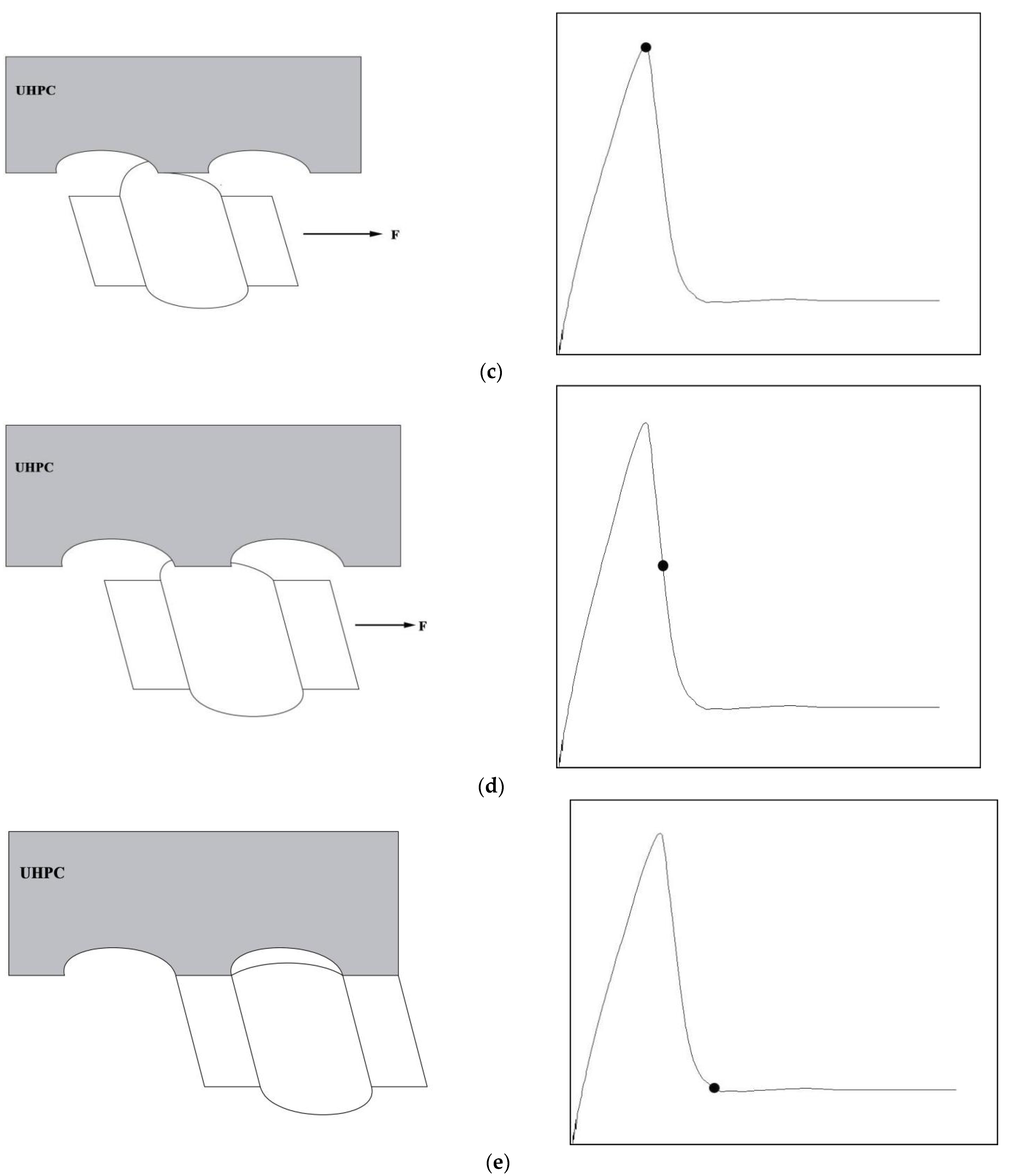
Initial stage: At the initial loading stage, the slip at the loading end increases gradually. However, due to the high initial stiffness of the system, no noticeable slip is observed at the free end [14]. During this stage, the tensile load is jointly resisted by the chemical bonding force and static frictional force at the interface between CFRP bars and UHPC, as illustrated at position “a” in Figure 20.
Mechanical interlocking stage: In this stage, frictional contact between CFRP bars and UHPC induces a certain degree of wear, leading to a gradual attenuation of the frictional force. Consequently, the mechanical interlocking force becomes the dominant component of the interfacial bonding effect. Additionally, under external loading, radial splitting forces are generated, causing transverse deformation of the UHPC matrix; however, this deformation does not reach the tensile strength of UHPC, and thus, no cracking occurs within the matrix. Benefiting from the high tensile strength and elastic modulus of UHPC, the interfacial bond stress increases rapidly during this stage, approximately exhibiting a linear growth trend, as illustrated at position “b” in Figure 20.
Peak bond stress stage: At this stage, the interlocking effect between the ribs on the surface of CFRP bars and the protrusions of the UHPC matrix reaches its maximum intensity. The crests of the CFRP bar ribs penetrate the narrowest regions between the UHPC protrusions. At this point, the mechanical interlocking resistance between the CFRP bars and UHPC is maximized; concurrently, the frictional force also reaches its peak value owing to the tight interfacial bonding between the CFRP bars and UHPC. The resultant force of these two components constitutes the peak interfacial bond stress, as illustrated at position “c” in Figure 20.
Bond degradation stage: As slip continues to increase, the slip magnitude exceeds half the width of the ribs on the CFRP bars. The radial splitting forces generated during the peak stage induce the propagation of microcracks within the UHPC matrix, which consequently loses its capacity to constrain the CFRP bar ribs—resulting in a gradual weakening of the mechanical interlocking force. Meanwhile, debris generated by frictional wear may accumulate at the interface between CFRP bars and the UHPC matrix, forming a “lubricating layer” that further reduces frictional resistance, as illustrated at position “d” in Figure 20.
Residual bond stage: At this stage, the slip magnitude has exceeded the full width of a single rib on the CFRP bar. Although the mechanical interlocking effect is significantly attenuated, the surface roughness of the CFRP bars and the residual deformation of the UHPC matrix can still provide a certain degree of bond resistance. At this point, the bond strength has decreased to its minimum value, and the interaction between the two materials reaches a dynamic equilibrium state. Consequently, the interfacial bond stress tends to stabilize, exhibiting favorable ductility, as illustrated at position “e” in Figure 20.

5.2. Bond Force Transfer Mechanism

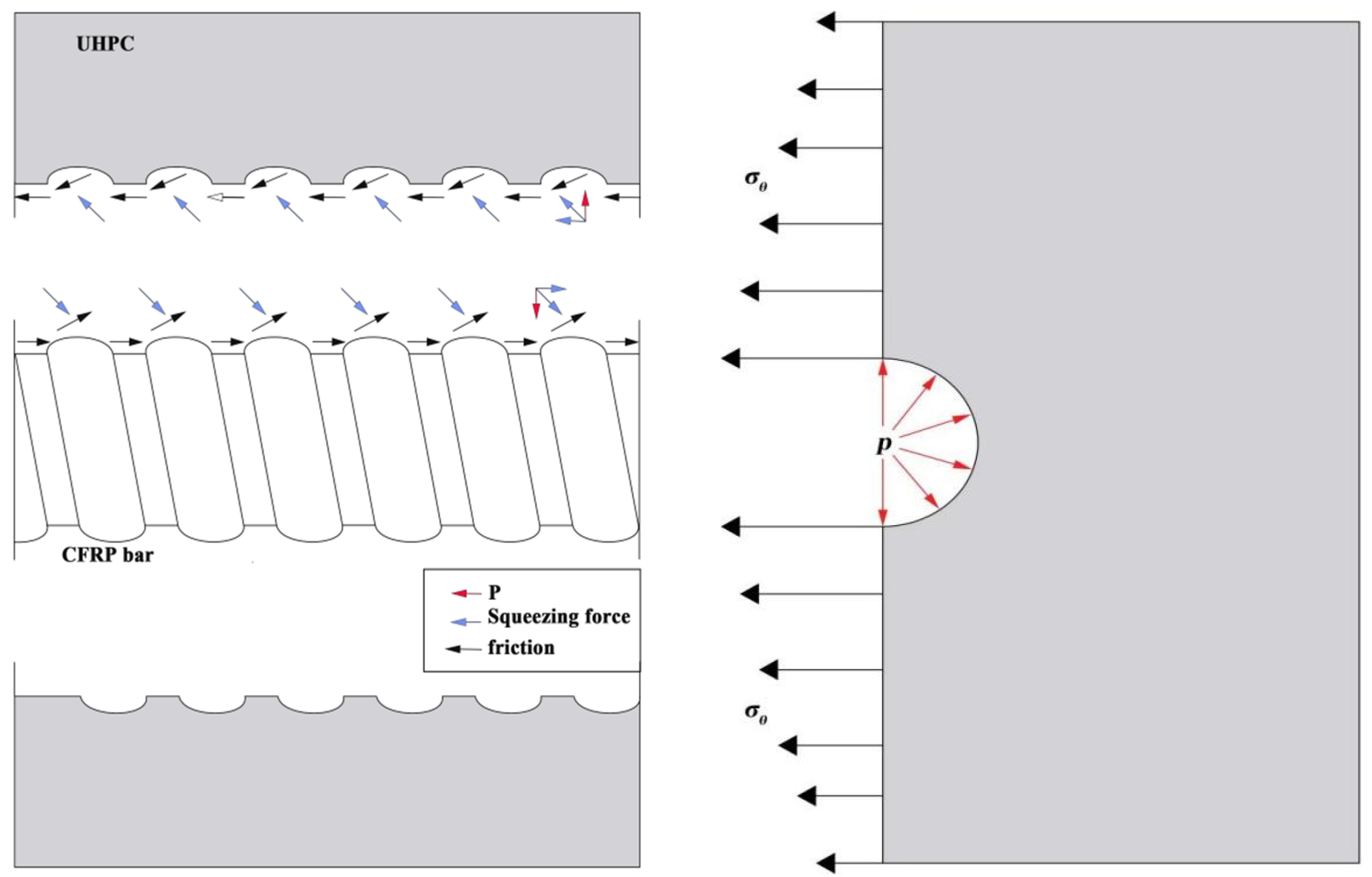
The bond force between CFRP bars and UHPC serves as the fundamental basis for their synergistic work. Bond failure can result in sudden fracture or excessive deformation of structural members, and research on the bond force transfer mechanism provides a theoretical basis for the durability design of such structures. As illustrated in Figure 21, during the pull-out process of CFRP bars from the UHPC matrix, the mechanical interlocking effect between the ribs of the CFRP bars and the surrounding UHPC exerts an oblique compressive action on the UHPC positioned in front of the bar ribs. The longitudinal component of this interlocking-induced compressive force, combined with the frictional force, jointly constitutes the interfacial bond stress between UHPC and CFRP bars.
Conversely, suppose the circumferential tensile stress does not exceed the tensile strength of UHPC. In that case, the specimen exhibits direct pull-out failure (characterized by severe shear damage to the transverse ribs of the CFRP bars) due to the strong gripping effect of UHPC on the CFRP bars and the relatively low shear strength of the bars [30].

6. Conclusions and Discussion

This study investigated the bond–slip mechanism between ribbed CFRP bars and UHPC using the ABAQUS finite element (FE) software. Finite element models of center-pull tests were developed for CFRP bars with three surface morphologies, three diameters, and four rib spacings. The influence of various geometric parameters on the bond–slip behavior was systematically elucidated. The main conclusions are summarized as follows:
  • For CFRP bars with diameters of 16 mm and 14 mm, and corresponding rib spacings of 1.0D and 1.2D, the bond strength of equal-height-ribbed bars exceeded that of crescent-ribbed bars by 40.6–45.9% and that of spiral-ribbed bars by 17.3–41.8%.
  • The surface morphology of CFRP bars exerted a significant influence on the interfacial bond strength between CFRP bars and UHPC. Benefiting from the uniform stress distribution induced by their geometric symmetry, equal-height-ribbed CFRP bars exhibited the optimal bond behavior and thus possessed greater reliability in engineering applications.
  • Within a specific range of bar diameters, the interfacial bond strength between CFRP bars and UHPC decreased with an increase in CFRP bar diameter; however, the overall influence of diameter was relatively minor. For CFRP bars with diameters ranging from 12 mm to 16 mm, the interfacial bond strength decreased by 12–15% for every 4 mm increase in diameter.
  • For 12 mm-diameter equal-height-ribbed CFRP bars with a rib spacing of 14.4 mm, the interface between the CFRP bars and UHPC achieved the peak interfacial bond strength. Furthermore, the slip magnitude corresponding to the peak interfacial bond strength exhibited a positive correlation with the peak interfacial bond strength itself.
  • During the bond–slip process between CFRP bars and UHPC, the stress of the CFRP bars along the anchorage length exhibited a distinct nonlinear distribution characteristic. As the slip magnitude increased, the bar stress gradually increased, with stress values being higher at locations closer to the loading end.
  • This study investigated three factors influencing the bond–slip behavior between UHPC and CFRP bars. Several other factors, however, were not considered, such as concrete cover thickness, the volume fraction of steel fibers in UHPC, and anchorage length. Future research could delve deeper into the effects of these unaddressed factors on the bond–slip performance between UHPC and CFRP bars.
  • This work primarily focused on the bond performance between UHPC and CFRP bars under monotonic static loading. In practical engineering applications, however, these materials are subjected to various factors such as freeze–thaw cycles, chloride ion erosion, and dynamic loads. Subsequent studies are encouraged to investigate the bond degradation mechanisms under individual or even coupled multi-factor conditions.

Author Contributions

Conceptualization, J.J.; Methodology, N.L. and C.K.; Software, J.J. and N.L.; Validation, N.L. and C.K.; Formal analysis, J.J.; Investigation, N.L.; Resources, J.J. and C.K.; Data curation, J.J., N.L. and C.K.; Writing—original draft, N.L.; Writing—review & editing, J.J., N.L. and C.K.; Visualization, C.K.; Supervision, C.K. All authors have read and agreed to the published version of the manuscript.

Funding

This research received no external funding. The APC was funded by Nachuan Liu.

Data Availability Statement

The original contributions presented in this study are included in the article. Further inquiries can be directed to the corresponding author.

Conflicts of Interest

The authors declare no conflict of interest.

References

  1. Fan, D.Q.; Yu, R.; Fu, S.Y.; Yue, L.; Wu, C.F.; Shui, Z.H.; Liu, K.N.; Song, Q.L.; Sun, M.J.; Jiang, C.Y. Precise design and characteristics prediction of Ultra-High Performance Concrete (UHPC) based on artificial intelligence techniques. Concr. Compos. 2021, 122, 104171. [Google Scholar] [CrossRef]
  2. Abellan-Garcia, J.; Abbas, Y.M.; Khan, M.I.; Martínez-Lirón, V. Ductility characteristics of strain-hardening ultra-high-performance concrete: ANN and empirical approaches. Comput. Concr. 2025, 35, 603–617. [Google Scholar] [CrossRef]
  3. Lyu, X.; Ayough, P.; Nawaz, W.; Elchalakani, M. Development and characterization of printable rubberised ultra-high-performance concrete. J. Build. Eng. 2025, 111, 113192. [Google Scholar] [CrossRef]
  4. Qiu, Z.T.; Deng, M.K.; Wei, D.; Tian, X.L.; Li, R.Z. Axial compressive behaviour of H-shaped steel members strengthened with ultra-high performance concrete with coarse aggregates (CA-UHPC): Experimental study and theoretical analysis. Constr. Build. Mater. 2025, 493, 143257. [Google Scholar] [CrossRef]
  5. Zhang, Y.X.; Zhang, Q.; Xu, L.Y.; Hou, W.; Miao, Y.S.; Liu, Y.; Huang, B.T. Transfer learning for intelligent design of lightweight Strain-Hardening Ultra-High-Performance Concrete (SH-UHPC). Autom. Constr. 2025, 175, 106241. [Google Scholar] [CrossRef]
  6. Yoo, S.J.; Hong, S.H.; Yoon, Y.S. Bonding behavior and prediction of helically ribbed CFRP bar embedded in ultra high-performance concrete (UHPC). CASE Stud. Constr. Mater. 2023, 19, e02253. [Google Scholar] [CrossRef]
  7. Wu, M.Z.; Xu, J.C.; Li, W.Y.; Li, W.W.; Wang, C.G.; Wang, P. Axial compression behaviour of concrete columns with CFRP-mesh fabric (CFRP-MF) stirrup and steel-FRP composite bar (SFCB): Experimental investigation and mechanism research. Constr. Build. Mater. 2024, 436, 136853. [Google Scholar] [CrossRef]
  8. Zhou, Y.W.; Zheng, X.B.; Xing, F.; Sui, L.L.; Zheng, Y.W.; Huang, X.X. Investigation on the electrochemical and mechanical performance of CFRP and steel-fiber composite bar used for impressed current cathodic protection anode. Constr. Build. Mater. 2020, 255, 119377. [Google Scholar] [CrossRef]
  9. Li, S.; Sun, J.R.; Guo, Y.Q. Method of measuring the mechanical impact loads of lightning on CFRP composites. Acta Mater. Compos. Sin. 2025, 42, 5994–6005. [Google Scholar] [CrossRef]
  10. Yuan, J.Q.; Graybeal, B. Bond of Reinforcement in Ultra-High-Performance Concrete. ACI Struct. J. 2015, 112, 851–860. [Google Scholar] [CrossRef]
  11. Xie, J.; Wang, X.H.; Liu, Y. Numerical analysis on bonding performance between CFRP bar and concrete at polar low temperatures. J. Harbin Inst. Technol. 2024, 56, 1–13. [Google Scholar] [CrossRef]
  12. Ouyang, L.Z.; Song, X.B.; Yin, C.R.; Xiao, X.W.; Qi, L.G. Bond behavior between CFRP bars with different surface characteristics and concrete. China Civ. Eng. J. 2025, 1–11. [Google Scholar] [CrossRef]
  13. Chen, J.X.; Fang, Z.; Fang, W.C.; Wang, Q.W.; Tan, X.Y. Experimental Study on the Bond Behavior of the CFRP Bar-UHPC Interface in Composite Anchorage. J. Compos. Constr. 2025, 29, 04025015. [Google Scholar] [CrossRef]
  14. Fahmy, M.F.M.; Ahmed, S.A.S.; Wu, Z.S. Bar surface treatment effect on the bond-slip behavior and mechanism of basalt FRP bars embedded in concrete. Constr. Build. Mater. 2021, 289, 122844. [Google Scholar] [CrossRef]
  15. Jafari, A.; Shahmansouri, A.A.; Abdulridha, H.A.; Issa, B.I.; Bengar, H.A. Effect of CFRP confinement on bond-slip behavior of steel rebar in low-strength concrete: Experimentation, prediction and parametric study. Constr. Build. Mater. 2025, 477, 141333. [Google Scholar] [CrossRef]
  16. Shahmansouri, A.A.; Jafari, A.; Bengar, H.A.; Zhou, Y. Steel rebar bond-slip behavior in CFRP-strengthened low-strength concrete: ML-driven solution and reliability analysis. Constr. Build. Mater. 2025, 490, 142302. [Google Scholar] [CrossRef]
  17. GB50152-2012; Standard for Test Method of Concrete Structures. Ministry of Housing and Urban-Rural Development PRC: Beijing, China, 2012. (In Chinese)
  18. Gu, J.F.; Ren, Q.W. Study on hydraulic concrete cracking criterion in smeared crack numerical model. Eng. Mech. 2015, 32, 84–91. [Google Scholar]
  19. Chiew, S.M.; Ibrahim, I.S.; Jamaluddin, N.; Sarbini, N.N.; Ma, C.K.; Ahmad, Y. Behavior of Steel Fiber-Reinforced Concrete under Biaxial Stresses. ACI Struct. J. 2020, 117, 267–278. [Google Scholar] [CrossRef]
  20. Sarikaya, A.; Erkmen, R.E. A plastic-damage model for concrete under compression. Int. J. Mech. Sci. 2019, 150, 584–593. [Google Scholar] [CrossRef]
  21. Kmiecik, P.; Kaminski, M. Modelling of reinforced concrete structures and composite structures with concrete strength degradation taken into consideration. Arch. Civ. Mech. Eng. 2011, 11, 623–636. [Google Scholar] [CrossRef]
  22. Hassan, M.; Benmokrane, B.; ElSafty, A.; Fam, A. Bond durability of basalt-fiber-reinforced-polymer (BFRP) bars embedded in concrete in aggressive environments. Compos. Part B Eng. 2016, 106, 262–272. [Google Scholar] [CrossRef]
  23. Karataş, M.A.; Gökkaya, H. A review on machinability of carbon fiber reinforced polymer (CFRP) and glass fiber reinforced polymer (GFRP) composite materials. Def. Technol. 2018, 14, 318–326. [Google Scholar] [CrossRef]
  24. Shan, B. Experimental Studies on Long-Term Behavior of FRP Retrofitted RC Columns with Earthquake Loading Damage. Ph.D. Thesis, Hunan University, Changsha, China, 2002. [Google Scholar]
  25. Zhang, Z. Bending Behaviors of Composite Bridge Deck System Composed of OSD and Reinforced UHPC Layer. Ph.D.Thesis, Hunan University, Changsha, China, 2016. [Google Scholar]
  26. Guan, P.; Tu, Y.; Zhang, P.; Tang, G. A review on constitutive relationship of ultra-high-performance concrete under uniaxial compression and tension. Acta Mater. Compos. Sin. 2019, 36, 1295–1305. [Google Scholar]
  27. Jin, L.; Liu, K.X.; Zhang, R.B.; Yu, W.X.; Du, X.L. Bond behavior between steel bar and concrete considering cryogenic temperatures and confinement. CASE Stud. Constr. Mater. 2023, 18, e01856. [Google Scholar] [CrossRef]
  28. Jiang, Z.W.; Liu, P.J.; Fang, Z.; Fang, Y.W.; Wang, Z.W. Experimental study on bonding behavior between CFRP smooth bar and UHPC under impact loading. Acta Mater. Compos. Sin. 2024, 41, 858–870. [Google Scholar] [CrossRef]
  29. Hsu, T.T. Unified Theory of Reinforced Concrete; Routledge: London, UK, 2017. [Google Scholar]
  30. Pan, R.S.; Zou, J.Y.; Liao, P.; Li, C.X. Experimental study and calculating method for bond strength between helically ribbed GFRP bar and UHPC. Zhongguo Gonglu Xuebao/China J. Highw. Transp. 2023, 36, 144–156. [Google Scholar]
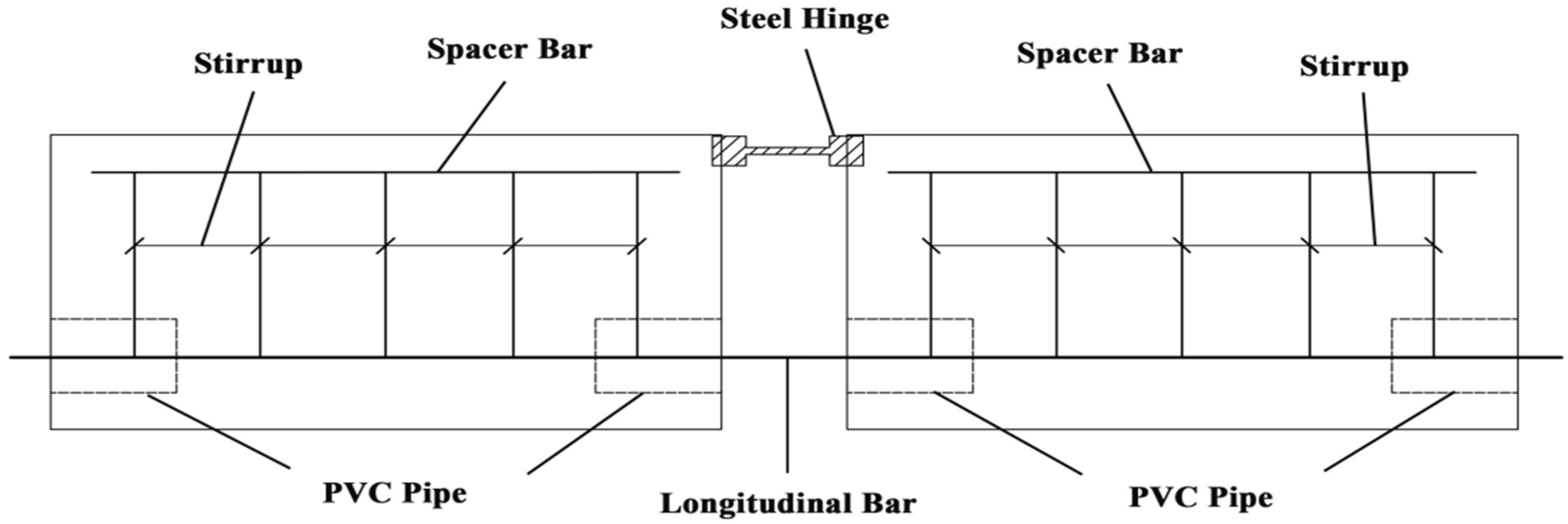
Figure 1. Beam test.
Applsci 15 11066 g001
Figure 2. Central-Pull Test.
Applsci 15 11066 g002
Figure 3. Schematic of rib geometries of CFRP ribbed bars.
Applsci 15 11066 g003
Figure 4. Finite element model of UHPC central pull-out test specimen.
Applsci 15 11066 g004
Figure 5. Stress–Strain Relationship of CFRP Bars.
Applsci 15 11066 g005
Figure 6. Compressive constitutive relationship of UHPC.
Applsci 15 11066 g006
Figure 7. Tensile constitutive relationship of UHPC.
Applsci 15 11066 g007
Figure 8. Comparison of simulated and experimental bond–slip curves.
Applsci 15 11066 g008
Figure 9. (a) Spiral-ribbed bars; (b) crescent-ribbed bars; (c) equal-height-ribbed bars.
Applsci 15 11066 g009
Figure 10. Effect of Different Surface Morphologies on Bond Performance of CFRP Bars.
Applsci 15 11066 g010
Figure 11. Effect of different diameters of CFRP bars on bond–slip behavior.
Applsci 15 11066 g011
Figure 12. Variation in peak bond stress with diameter of CFRP bars.
Applsci 15 11066 g012
Figure 13. Effect of different rib spacings on bond–slip behavior.
Applsci 15 11066 g013
Figure 14. Axial stress contour plots of CFRP bars with different rib spacings (unit: MPa).
Applsci 15 11066 g014
Figure 15. Axial stress contour plots of CFRP bars with different rib spacings (unit: MPa).
Applsci 15 11066 g015
Figure 16. Concrete rib shear stress at 0.8D rib spacing (unit: MPa).
Applsci 15 11066 g016
Figure 17. Concrete rib shear stress at 1.0D rib spacing (unit: MPa).
Applsci 15 11066 g017
Figure 18. Concrete rib shear stress at 1.2D rib spacing (unit: MPa).
Applsci 15 11066 g018
Figure 19. Concrete rib shear stress at 1.6D rib spacing (unit: MPa).
Applsci 15 11066 g019
Figure 20. Bonding mechanism between CFRP bars and UHPC.
Applsci 15 11066 g020aApplsci 15 11066 g020b
Figure 21. Bond transferring mechanism between CFRP bar and UHPC (бθ is the hoop tensile stress in UHPC; P is the radial component of the compressive force).
Applsci 15 11066 g021
Table 1. Comparison of characteristic values of bond–slip curves between pull-out tests and numerical simulations.
CategoryExperimental ValueNumerical Simulation ValueError Value
Peak Bond Strength (Mpa)3.413.460.05
Peak Bond Slip (mm)0.970.850.12
Disclaimer/Publisher’s Note: The statements, opinions and data contained in all publications are solely those of the individual author(s) and contributor(s) and not of MDPI and/or the editor(s). MDPI and/or the editor(s) disclaim responsibility for any injury to people or property resulting from any ideas, methods, instructions or products referred to in the content.