1. Introduction
The accelerated adoption of EVs has placed increasing demands on the development of safe, lightweight, and crash-resilient energy storage systems. LIBs, owing to their high energy density and compact form factor, are central to EV functionality. However, they remain susceptible to mechanical failures during collision events, which may lead to hazardous outcomes such as thermal runaway, electrolyte leakage, or internal short-circuiting. Addressing these vulnerabilities is not only essential but also urgent for ensuring the safety and sustainability of widespread EV deployment.
While extensive research has focused on failure mechanisms at the cell level under abusive mechanical conditions, such as indentation, penetration, and compression [
1,
2,
3], Compared to other aspects, comparatively less attention has been directed toward the structural integrity of battery enclosures. Battery frames play a critical role in shielding cells from impact while simultaneously maintaining minimal mass, a key requirement for maximizing vehicle efficiency and driving range [
4].
In this context, engineered lattice structures have gained interest due to their customizable geometries, high strength-to-weight ratios, and ability to absorb mechanical energy. With the advancement of additive manufacturing techniques, such as Fused Deposition Modeling (FDM), it is now feasible to fabricate complex, load-specific lattice configurations. Prior research has demonstrated the advantages of bioinspired cellular geometries, including spider-web frameworks [
5], lotus root-inspired pore patterns [
6], and optimized honeycomb arrangements [
7], in enhancing crashworthiness with minimal additional weight. However, most of these designs rely on repetitive, uniform unit cells, which limit structural adaptability under variable loading.
Nature, by contrast, offers a vast repertoire of hierarchical and irregular architectures optimized for impact resistance and lightweight performance. Among these, the horn of the bighorn sheep (Ovis canadensis) represents a striking biological model, combining toughness, lightweight structure, and progressive energy absorption [
8,
9]. Its natural optimization provides valuable design cues for engineering next-generation crashworthy enclosures.
Inspired by this biological paradigm, the present study introduces a multilayered battery frame modeled after the geometric and material composition of the bighorn sheep’s horn. This innovative design aims to improve the mechanical robustness and impact mitigation of LIBs in EVs. To evaluate the effect of both material properties and internal architecture, two contrasting materials were selected: Acrylonitrile Butadiene Styrene (ABS), a ductile thermoplastic known for its impact resistance and ease of fabrication, and Carbon-Fiber-Reinforced Composite (CFC), a high-strength material with superior stiffness and specific strength.
This dual-material investigation facilitates a holistic assessment of how bioinspired architectures interact with material behavior under mechanical loads. The study explores structural performance under uniaxial tension, compression, and impact loading, Acoustic Emission (AE), with strain fields analyzed using Digital Image Correlation (DIC).
In summary, the bioinspired hybrid frame, modeled after the bighorn sheep horn, exhibits enhanced energy absorption, superior crash mitigation, and improved structural efficiency compared to monolithic or conventional designs. This research underscores the potential of nature-inspired, multifunctional battery frames as a next-generation solution for EV safety and structural performance.
1.1. Literature Review on Bighorn Sheep Horn-Inspired Designs
Recent studies have directly drawn inspiration from the architecture of the bighorn sheep’s horns for impact-resistant structural design. For instance, Babu et al. developed horn-inspired metamaterial lattices using Multi Jet Fusion (MJF) 3D printing. Their designs, incorporating curvature and thickness variations, achieved a 25.4% increase in specific energy absorption compared with straight-walled designs and a 52.8% improvement over classical Kelvin foams, clearly confirming the efficiency of adopting horn-inspired geometries for energy absorption [
10]. Unlike that study, which modeled the horn’s overall geometry, the present work focuses on inner structural details, employing a multilayered hierarchical design with a rigid outer shell.
Beyond global geometry, another study has investigated horncore microarchitecture, which consists of a sponge-like trabecular network. Additively manufactured replicas of this architecture have demonstrated excellent energy absorption under both quasi-static and dynamic loading, with potential applications extending to non-biological domains such as protective foams and impact-absorbing insoles [
11,
12].
From a modeling perspective, finite element analyses of spiral and ridged horns revealed that surface corrugations and helical curvature can reduce initial impact pressures by up to 20% while promoting shear wave propagation [
13]. This mechanism contributes to stress redistribution and mitigation of localized failure, aligning with principles applied in rigid outer shells or lattice frameworks.
On the materials side, Reverte et al. demonstrated that the carbon-fiber reinforcement of PLA increased the tensile modulus by nearly 179.9% and the tensile strength by 47.1% compared to neat PLA, underscoring the impact of fiber reinforcement on additively manufactured specimens [
14]. Similarly, Harish et al. reported that PLA-based bioinspired lattices exhibited significantly higher compressive strength and energy absorption compared to simple lattices [
15]. Kushwaha et al. further demonstrated that tube orientation and geometric parameters strongly influenced the energy absorption and stress response of sheep horn-inspired structures under both quasi-static and dynamic loading [
12].
Taken together, these works confirm the effectiveness of reinforcement strategies, porous/lattice architectures, and bioinspired geometries in enhancing mechanical performance. However, most studies have focused on single aspects, such as lattice design or fiber reinforcement, without addressing the multi-scale integration found in nature. In contrast, the present study adopts a multilayer and hierarchical design, a rigid outer shell, a tubular middle layer, and a porous core, while simultaneously comparing two material systems (ABS and CFC) across tensile, compressive, and Izod impact loading. Moreover, the integration of complementary analysis methods such as DIC and AE provides a broader insight into deformation and failure mechanisms, advancing beyond the scope of previous horn-inspired studies.
1.2. Bioinspired Design
Nature offers a wealth of inspiration for impact-resistant structural design, with the horn of the bighorn sheep (Ovis canadensis) standing out as a remarkable example. These horns, which have evolved to withstand the intense forces generated during head-to-head combat, often exceeding 3400 N, approximately 60 times the force required to fracture a human skull, enable rams to engage in repeated collisions without sustaining injury [
16]. This extraordinary resilience has facilitated efficient load redistribution, delayed crack propagation, and provided exceptional energy absorption in the radial direction, which aligns directly with the orientation of the impact.
Compared with cattle or goat horns, which exhibit simpler internal microstructures and experience less severe impact demands, bighorn sheep horns display significantly greater energy dissipation capacity [
17]. Cattle horns, though mechanically strong, are not optimized for repeated high-energy collisions, whereas goat horns are lighter but more brittle, offering limited crack resistance. In contrast, the bighorn sheep’s horn achieves an exceptional balance of stiffness, toughness, and lightweight characteristics [
17]. This unique combination makes it an ideal biomimetic model for engineering crashworthy structures, providing design cues highly relevant to protective enclosures in EVs, where impact resistance, progressive failure behavior, and weight reduction are critical.
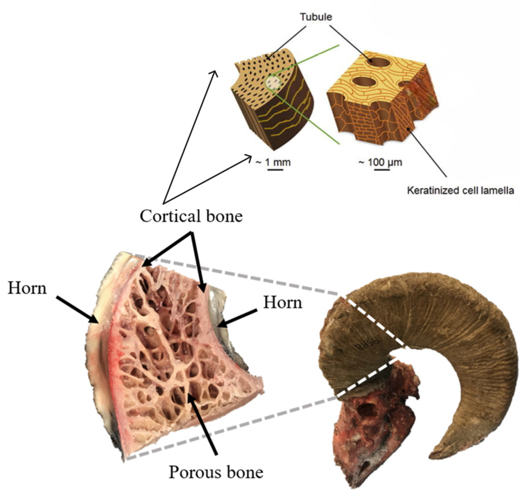
Anatomically, the horn consists of two primary structural components: a rigid outer keratin sheath and a porous inner bony core. The keratin layer, ranging from 2 to 5 mm in thickness, comprises aligned lamellar structures embedded with elliptical tubules oriented along the horn’s growth direction. This configuration imparts high axial stiffness while maintaining lateral flexibility, an optimal combination for dissipating impact energy without fracturing [
18]. Beneath the sheath lies the cortical horncore, which exhibits a lightweight foam-like network of plate-shaped trabeculae. Despite comprising only ~20% of the horn’s volume, this open-cell structure is capable of storing up to three times more strain energy than the outer layer during impact events [
11], as shown in
Figure 1.
Microscale investigations further reveal sophisticated toughening mechanisms. In related species such as the African buffalo (Syncerus caffer), the keratin structure of the horn features corrugated morphologies with alternating stiff and compliant regions, rich in disulfide cross-links (~2.6 wt% sulfur). These microstructural variations effectively divert and arrest crack propagation, thereby enhancing fracture resistance [
19]. The keratin sheath itself demonstrates tensile strengths reaching 183 MPa and fracture energies as high as 36.8 MJ/m
3, surpassing many commercial polymers [
19]. Moreover, hydration has been shown to reduce keratin stiffness by approximately 30%, while simultaneously boosting energy absorption by up to 50%, a phenomenon known as environment-responsive damping [
20]. This adaptive behavior allows the horn to maintain protective performance under varying environmental conditions, adding a layer of functional resilience. These properties of the keratin structure are directly applicable to the design of resilient battery structures, as they can enhance the battery’s ability to withstand mechanical stress and maintain performance under varying conditions.
At the macroscale, the horn’s helical curvature plays a crucial role in wave redirection. By gradually converting axial impact waves into torsional and bending modes, the spiral geometry helps distribute stress across a broader surface area, thereby reducing localized damage. Experimental drop-weight testing on spiral-ridged horn replicas has demonstrated a 21% reduction in peak force and an 8% increase in energy dissipation compared to smooth, unstructured controls [
18]. These effects stem from the structure’s ability to convert damaging high-frequency compressive waves into lower-frequency shear modes, which are more easily dissipated.
The horn’s failure mechanisms are also uniquely optimized. Rather than exhibiting an abrupt fracture, the structure undergoes a controlled sequence of damage: delamination of keratin lamellae, shearing of internal scales, and eventual fiber pull-out. Each of these stages absorbs energy incrementally, delaying catastrophic failure and enhancing overall toughness [
21]. This staged, energy-dissipating failure strategy, which allows the structure to absorb and dissipate energy in a controlled manner, is central to the current study’s approach to battery frame design. By incorporating similar staged failure mechanisms into the design of battery frames, we can provide a protective buffer for vulnerable battery modules during mechanical impact, thereby enhancing the safety and reliability of the battery system.
From these natural insights, five key design principles emerge: (1) spiral geometry for impact wave steering; (2) corrugated ridges for crack deflection; (3) hierarchical porosity combining a dense shell and porous core; (4) progressive, staged failure mechanisms; and (5) moisture-sensitive damping. Collectively, these principles offer a robust framework for engineering lightweight, resilient protective structures.
These concepts are already being translated into engineered solutions. For instance, 3D-printed spiral lattice composites have demonstrated the ability to retain approximately 70% of the stiffness of solid beams while reducing weight by more than 50% [
22]. Likewise, metallic foams inspired by trabecular bone achieve comparable energy absorption to EVA foams while cutting mass by up to 75% [
22].
Building upon this biomimetic foundation, the present study introduces a bioinspired LIB frame fabricated using Fused Deposition Modeling (FDM) and Carbon Fiber-Reinforced Composite (CFC). The proposed design incorporates a spiral outer grid structure to redirect impact waves, a stiffened shell layer to impede crack propagation, and a plate-based lattice core that mimics the energy absorption properties of trabecular bone. This multilayered configuration is engineered to provide a crash-resilient, lightweight housing for EV battery modules, advancing structural safety and promoting long-term reliability in next-generation electric mobility platforms.
Figure 1.
Hierarchical structure of the bighorn sheep horn illustrating bioinspired design potential for energy absorption. The horn comprises a keratinized sheath (~100 μm scale tubules) and porous bone regions (~1 mm cortical lamella), showcasing multiscale mechanical adaptations for energy absorption [
23], with permission from Elsevier, Copyright (2021).
1.3. Biomimetic Design Strategy and Structural Translation
The battery frame developed in this study is a testament to the precision and innovation that biomimicry can achieve. By directly drawing inspiration from the hierarchical architecture of the bighorn sheep’s horn, a naturally optimized structure known for its exceptional impact tolerance, this design translates key anatomical features and associated microscale toughening mechanisms into a three-tiered engineered system. Each layer was purposefully modeled to replicate both the biological form and its underlying deformation modes, showcasing the innovative potential of biomimicry in materials science and battery technology.
The outermost layer, designed to mirror the horn’s dense keratin sheath, plays a pivotal role in protecting the battery. In the natural horn, this sheath delays crack initiation and redirects propagating cracks through a lamellar microstructure. In the engineered frame, this mechanism is represented by a rigid continuous shell that resists surface fracture, distributes contact stresses, and preserves geometric integrity under impact, ensuring the safety and longevity of the battery.
The intermediate layer draws from the horn’s internal tubule alignment, featuring elliptical microchannels oriented longitudinally along the growth axis, which guide stress waves and enhance radial reinforcement. In the synthetic design, this is reinterpreted as an array of vertically aligned cylindrical channels. These channels mimic the crack-bridging and stress-guiding functions of the natural tubules, thereby regulating load transfer and controlling the progression of deformation.
At the core lies the inner layer, inspired by the trabecular horn core. Biologically, this porous network dissipates energy through progressive collapse and plastic buckling of trabeculae. In the CAD model, which was created using Autodesk Netfabb, this was translated into an open-cell lattice architecture. This architecture replicates distributed crushing and staged failure while maintaining low density. The CAD model played a crucial role in the design process, ensuring that the gradual, energy-absorbing collapse observed in the biological structure is captured in the manufactured counterpart.
This multiscale, biologically informed configuration (illustrated in
Figure 2) aligns microscale toughening strategies with manufacturable features, enabling translation of crack deflection, wave steering, and progressive energy absorption into practical, additively manufactured geometries. By integrating rigid protection, directional reinforcement, and cellular dissipation into a cohesive CAD framework, the proposed battery frame offers a lightweight yet mechanically resilient solution for safeguarding LIB modules. The design not only reinforces the promise of nature-inspired engineering but also establishes a clear pathway for embedding biological toughening mechanisms into scalable structural materials, paving the way for a new era in battery technology.
2. Materials and Methods
2.1. Material Selection
In EV engineering, vehicle weight remains a central factor influencing range, energy efficiency, and overall system performance. Given that battery modules already constitute a significant share of total vehicle mass, the materials selected for their enclosures must achieve an optimal balance between mechanical strength and lightweight characteristics. Overly heavy casings not only undermine the energy savings associated with electrification but also reduce driving efficiency and performance benefits.
Two commercially available thermoplastic filaments were selected for specimen fabrication: a short carbon-fiber reinforced PLA composite and a bulk-polymerized ABS resin. This direct comparison between a high-stiffness, fiber-reinforced system and a more ductile thermoplastic baseline under identical bioinspired structural configurations was considered essential.
The composite material was PolyLite™ PLA-CF (Polymaker, Shanghai, China; distributed by Polymaker US, Charlotte, NC, USA), consisting of a polylactic acid (PLA) matrix reinforced with approximately 8 wt% chopped carbon fibers extruded as a 1.75 mm filament, referred to here as CFC. Unlike continuous fiber composites, short fibers introduce anisotropy in printed parts, with stiffness and strength being strongly dependent on the raster orientation. Manufacturer specifications report a density of 1.29 g/cm3, a tensile strength of 65–70 MPa, and a Young’s modulus of ~7.5 GPa. Due to its abrasive nature, the filament requires a hardened steel nozzle during processing. Recommended parameters include a nozzle temperature of 210–230 °C, a heated bed temperature of 30–70 °C, and moderate print speeds. The chopped carbon fibers enhance stiffness and dimensional stability, partially mitigating the brittle fracture behavior characteristic of PLA; however, the impact resistance remains lower compared to ductile polymers, such as ABS.
The ductile reference material was PolyLite™ ABS (Polymaker, Shanghai, China; distributed by Polymaker US, Charlotte, NC, USA). This bulk-polymerized ABS resin filament exhibits a density of ~1.12 g/cm
3 at ambient temperature (21–23 °C). Reported mechanical properties include a young modulus of ~2174 MPa (±285 MPa) and a tensile strength of ~33.3 MPa (±0.8 MPa). Recommended print settings are a nozzle temperature of 245–265 °C, a bed temperature of 90–100 °C, a cooling fan disabled, and filament drying at 70 °C for ~6 h if moisture is present [
24,
25].
2.2. Specimen Fabrication
In this study, 96 specimens (details in
Table 1) were fabricated using Fused Deposition Modeling (FDM) on a Bambu Lab X1 Carbon system (Bambu Lab, Shenzhen, China), which provides a closed-chamber environment essential for minimizing warping during ABS processing. Printing was performed with a 0.4 mm hardened steel nozzle, layer height of 0.20 mm, and a constant print speed of 40 mm/s. A 15% grid infill with two outer walls was applied to promote controlled energy absorption under loading while preserving structural integrity. Specimens were oriented in the XY plane to maintain the geometric accuracy of the bioinspired architecture. The nozzle temperature was set to 240 °C for ABS and 250 °C for CFC, with the build plate heated to 100 °C for ABS and 60 °C for CFC. Cooling fans were kept off during the first five layers to enhance layer adhesion, and then they were gradually activated. No post-processing or thermal treatments were applied before testing, ensuring the integrity of the as-printed structures.
Each specimen featured a bioinspired, multilayered internal structure with a total thickness of 12 mm, as depicted in
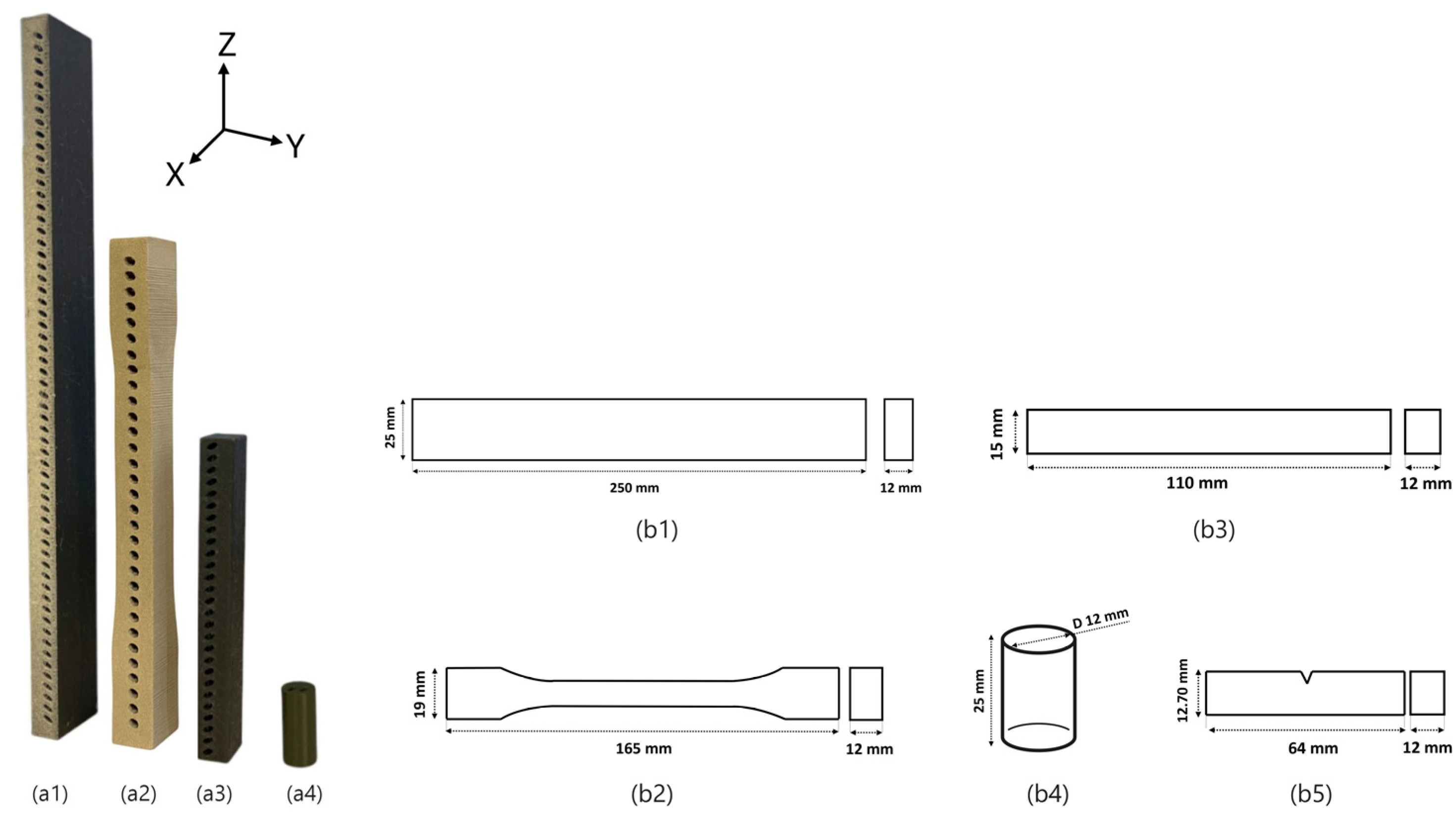
Figure 2. For enhanced visualization of the bioinspired configurations, representative structured specimens are additionally presented in
Figure 3, illustrating both tensile and compression designs for ABS and CFC. These examples emphasize the incorporation of the internal tubular architecture that distinguishes the structured samples from their solid control counterparts. The architecture consisted of three functional layers: a 2 mm solid outer shell mimicking the keratin sheath of the horn, a 5 mm intermediate tubular layer inspired by the aligned internal tubules, and a 5 mm porous lattice core replicating the trabecular horn core. The inner lattice was modeled in Autodesk Netfabb as an open-cell structure with an approximate relative density of 20%, optimized to deform progressively under loading. To ensure fabrication integrity and prevent delamination, a continuous 0.6 mm reinforcement wall encloses all internal layers.
The CAD models were uniformly scaled to a final thickness of 12 mm to accommodate the multilayered bioinspired design. This proportional scaling preserved the overall geometry and internal hierarchical features, allowing all specimens to be fabricated consistently within the intended design constraints (
Figure 3). While ASTM standards guided the specimen dimensions, minor adjustments were required to address the FDM process and the integration of internal layers. ASTM D3039 [
24] prepared tensile specimens for CFC (rectangular geometry) and ASTM D638 [
25] for ABS (dog-bone geometry). Compression specimens were tested according to ASTM D3410 [
26] for CFC and ASTM D695 [
27] for ABS. Izod impact specimens conformed to ASTM D256 [
28], with slight modifications in thickness to ensure consistent architecture across all tests (see
Figure 3(b5)).
2.3. Mechanical Testing Setups
To comprehensively evaluate the crashworthiness of the bioinspired battery frame structures, a combination of tensile, compression, and impact tests was employed. These complementary loading modes capture stiffness, strength, progressive crushing behavior, and energy absorption under both quasi-static and high-strain-rate conditions. The tensile performance of both ABS and CFC specimens was evaluated primarily through force–displacement analysis, which provides a direct measure of stiffness, ultimate strength, and absorbed energy. This approach was chosen because it allows straightforward comparison across different materials and structural configurations, while also serving as the baseline for correlating with synchronized stress–time responses, DIC strain fields, and AE signals. Together, these integrated measurements enabled correlations between global load-bearing capacity, localized deformation, and the initiation of micro-damage, offering a multiscale understanding of mechanical performance.
2.3.1. Tensile and Compression Testing
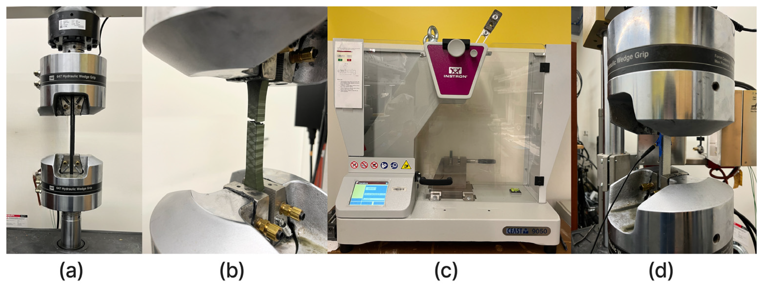
Tensile and compression tests were performed using an MTS 810 servo-hydraulic universal testing machine equipped with 647 hydraulic wedge grips (
Figure 4a,b). A total of 48 specimens were evaluated, as summarized in
Table 1. The loading rates were set to 2 mm/min for tensile tests (ASTM D638) and 1 mm/min for compression tests (ASTM D695), under controlled laboratory conditions (23 ± 2 °C). In all bioinspired specimens, the loading direction (tensile and compressive) was applied along the Z-axis, parallel to the stacking and growth direction of the horn-inspired layers. The tubular channels within the middle layer were oriented along the X-axis, perpendicular to the loading direction, while their sequence repeated along the Z-axis. This configuration emulates the natural micro-architectural alignment of bighorn sheep horns, where the tubule axes are transverse to the main impact direction, facilitating efficient stress redistribution and progressive energy absorption underloading. For both testing modes, force–displacement curves were recorded to evaluate stiffness, ultimate strength, energy absorption capacity, and progressive failure mechanisms.
2.3.2. Izod Impact Testing
Impact resistance was assessed using an Instron CEAST pendulum impact tester (
Figure 4c). Izod tests were conducted using a 2.75 J pendulum hammer, in accordance with ASTM D256, which specifies the specimen geometry, notch preparation, and test conditions. A total of 24 specimens were evaluated (Details in
Table 1). Each specimen was notched in a standardized manner, a crucial step that promotes crack initiation and ensures the validity of the experimental design and comparability between groups.
During testing, the pendulum hammer delivered a sudden impact load, and the absorbed energy was recorded directly from the machine’s digital acquisition system. This energy value reflects the material and structural ability to resist crack propagation and catastrophic failure under high-strain-rate conditions. Fracture surfaces were subsequently examined to distinguish brittle behavior in CFC from ductile yielding in ABS.
2.3.3. Digital Image Correlation (DIC)
Digital Image Correlation (DIC) was employed as a full-field, non-contact optical technique to monitor surface deformation during tensile and compression tests. Each specimen was coated with a high-contrast random speckle pattern, and high-resolution images were captured throughout the loading process. By tracking the displacement of speckles between frames, the system generated accurate strain and displacement fields with an impressive level of spatial resolution.
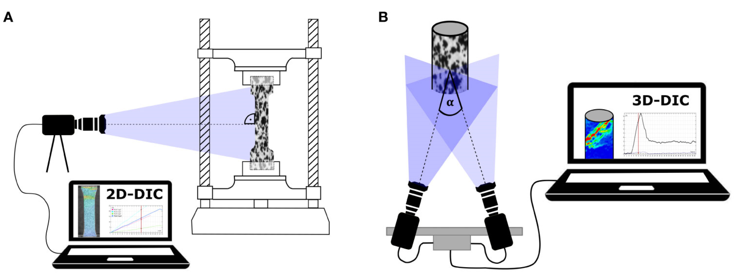
A 2D-DIC configuration was implemented, utilizing a single camera under controlled LED illumination. This approach assumes negligible out-of-plane motion and is well-suited for planar specimens such as those tested in this study. While 3D-DIC systems based on stereo imaging can capture three-dimensional strain states in curved or complex geometries, 2D-DIC was chosen here for its reliability and efficiency. This technique enabled visualization of localized strain concentrations, crack initiation, and energy dissipation within the layered structures, providing insights beyond conventional force–displacement measurements. Both the strain maps and the extracted ε
yy strain component were analyzed and directly compared with stress–time and AE signals. The experimental setup is illustrated in
Figure 5, which shows the camera, illumination system, speckled specimens, and synchronized data acquisition system.
2.3.4. Acoustic Emission (AE)
Acoustic emission (AE) monitoring was employed to capture transient elastic waves generated by microcracking, fiber–matrix debonding, and other damage processes during the tensile tests [
25]. Signals were captured in real time using a broadband piezoelectric sensor mounted directly on the specimen surface near the gauge region [
26]. To ensure consistent coupling, the specimen surface was lightly polished to remove debris, and the sensor was attached with a thin layer of vacuum grease and secured with adhesive tape. This setup enabled reliable signal transmission and continuous tracking of damage evolution during testing (
Figure 4).
The AE system was operated with a sampling frequency of 5 MHz (FS = 5,000,000 samples/s) and a preamplifier gain of 48 dB, which provided adequate sensitivity to detect low-magnitude emissions while preventing signal saturation at high loads. A high-pass filter of 20 kHz and a low-pass filter of 1 MHz were applied to reduce background noise and restrict the frequency content to the most relevant range of microcracking events. Signal acquisition was triggered at a threshold of 100 mV, with 1024 pre-trigger samples and a window length of 4096 samples, enabling detailed waveform capture of each AE event.
Amplitude was expressed in decibels (dB) re 1 µV, while signal energy was computed as the time integral of squared voltage (V2·s) after correcting for preamplifier gain and digitizer calibration. Post-processing involved waveform analysis, amplitude distribution, and cumulative energy calculations, which were synchronized with the mechanical load and strain data.
The AE setup (as shown in
Figure 4d) was carefully synchronized with the tensile testing system, allowing for one-to-one correlation between microscale acoustic activity and macroscale deformation fields. This enabled identification of the onset of microcracking, progressive fiber–matrix debonding, and the final catastrophic fracture. To ensure data fidelity, preliminary tests were performed without loading to confirm that environmental noise and machine vibrations were below the acquisition threshold.
3. Result and Discussion
3.1. Tensile Test Results
The tensile performance of both ABS and CFC specimens was evaluated through force–displacement analysis. As illustrated by the representative curves in
Figure 6 and the comparative bar plots in
Figure 7. There are clear and statistically significant differences between the structured and control configurations for both material types. These findings not only demonstrate the effectiveness of the bioinspired multilayer design in enhancing tensile resistance but also highlight the innovative and promising nature of this design. The tri-layer structure, consisting of a rigid outer shell, a tubular intermediate layer, and a porous core reinforced by an internal wall, contributes to improved load distribution, reduced stress concentrations, and a more progressive failure response.
Quantitative results presented in
Table 2 show that the CFC-structured group achieved the highest tensile strength (3046 N), followed by ABS-structured (2661 N), while both significantly outperformed their respective controls. Notably, structural effects surpassed material effects: ABS-structured specimens exhibited a 2.4-fold increase compared to ABS-control, and CFC-structured specimens more than doubled the load capacity of CFC-control.
A distinction, however, was observed in initial stiffness (K0). ABS-control specimens showed higher stiffness (1556 N/mm) than CFC-control (1372 N/mm), indicating greater resistance during the elastic stage. Yet, CFC-control sustained higher ultimate loads (1483 N vs. 1114 N). This is not contradictory but rather reflects different deformation mechanisms. ABS, being more ductile, resists early elastic deformation but fails at a lower peak stress. At the same time, CFC exhibits lower initial stiffness but greater ultimate strength due to its carbon-fiber reinforcement.
Statistical analysis (
Table 3) supported these findings. The differences between the structured and control groups were highly significant (
p < 0.001). The CFC-control also significantly outperformed ABS-control (
p = 0.009), affirming the superior tensile capacity of the fiber-reinforced composite.
Overall, the performance differences observed in tensile testing can be attributed to the combined influence of material properties and structural design. While carbon fiber reinforcement enhances the ultimate tensile capacity of CFC, the bioinspired multilayer geometry significantly improves mechanical behavior in both ABS and CFC. ABS specimens, in particular, benefit from increased energy absorption and deformation stability, whereas CFC specimens exhibit superior peak load resistance. These findings highlight the crucial role of structural architecture, demonstrating that in certain applications, design strategy can outweigh the impact of material selection. The nature-inspired hierarchical structure facilitates uniform stress distribution, delays the onset of failure, and enhances overall toughness, offering a promising pathway for the development of high-performance, load-bearing components in the field of materials science.
3.2. Compression Test Results
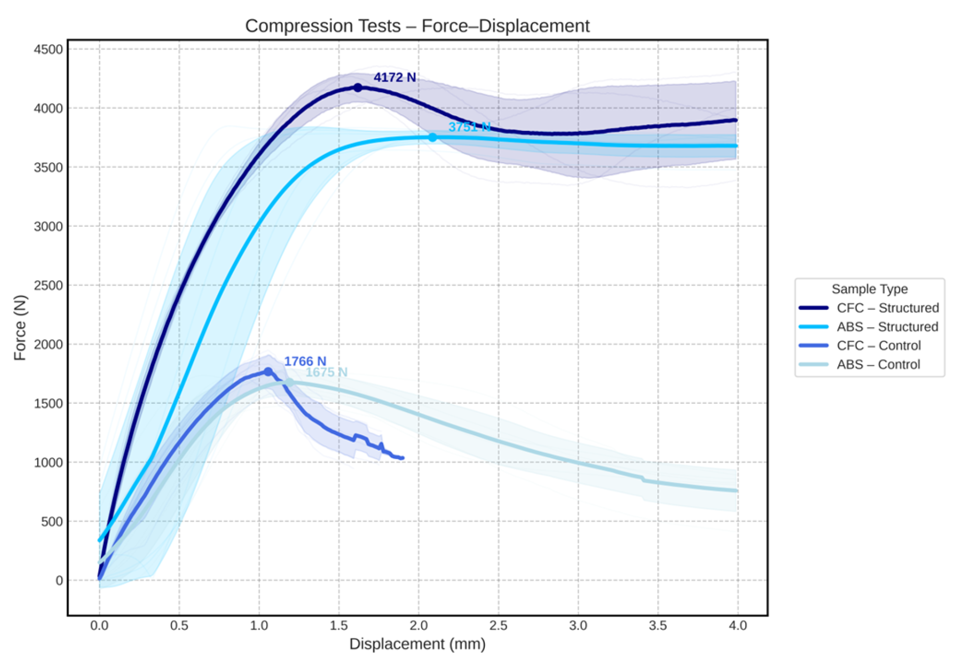
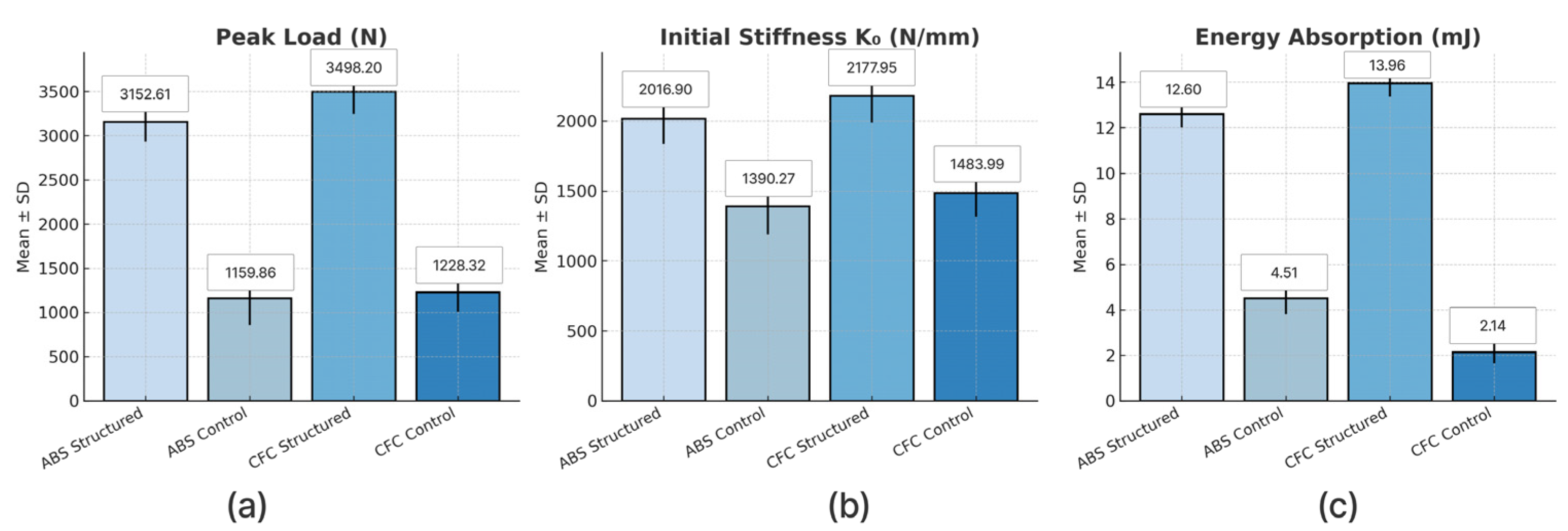
The compressive behavior of the four specimen groups, structured and control configurations of both ABS and CFC materials, was evaluated under quasi-static loading conditions. The force–displacement curves (
Figure 8), along with the statistical data provided in
Table 4 and
Table 5, and the comparative bar plots (
Figure 9), reveal marked differences in load-bearing capacity, initial stiffness, and energy absorption across all categories. The results highlight the dominant role of structural design over base material properties, particularly the enhanced performance of the CFC-structured and ABS-structured samples.
The CFC-structured group exhibited the highest compressive strength, reaching peak loads of approximately 4172 N, with a group mean of 3498.20 N, as shown in
Table 4. This superior performance is attributed to the combined effect of the material’s high intrinsic strength and the load-redistributing capabilities of the bioinspired multilayered architecture, which mimics the hierarchical structure found in natural materials. The structured geometry delays local failure and enables sustained loading by promoting more uniform stress distribution.
Remarkably, the ABS-structured specimens also demonstrated outstanding compressive strength, achieving a mean peak load of 3152.61 N, despite being based on a mechanically less stiff polymer. This result underscores the transformative impact of architectural design. The fact that ABS-structured samples outperformed CFC-control specimens highlights the capacity of bioinspired geometry to significantly enhance mechanical performance significantly, even when using lower-strength materials.
Both structured groups also showed markedly higher stiffness (CFC: 2178 N/mm; ABS: 2017 N/mm) and energy absorption (13.96 mJ and 12.6 mJ, respectively), whereas both control groups exhibited substantially lower compressive strength. The ABS-control and CFC-control samples recorded mean peak loads of 1159.86 N and 1228.32 N, respectively (
Table 4). In the absence of engineered geometry, these specimens failed prematurely due to localized buckling and instability. The fact that the difference between the two control groups was not statistically significant, with a
p-value of 0.292 (
Table 5), further highlights the importance of structural optimization over material selection alone in improving performance.
In summary, the results confirm the considerable advantages of applying hierarchical, bioinspired geometries to compressive load-bearing components. Improvements in compressive strength, stiffness, and energy absorption were observed across both materials, with robust performance gains in structured ABS specimens. These findings highlight the significance of structural optimization in enhancing performance, even when utilizing materials with modest mechanical properties. This has important implications for lightweight, crash-resistant applications such as battery protection enclosures in EVs.
3.3. Post-Peak Behavior and Residual Load Stability Under Tensile and Compression Loading
The results from the tensile and compressive tests unequivocally showcase the unique characteristics of the structured specimens. Their bio-inspired three-layered architecture sets them apart, leading to distinct behaviors in the later stages of deformation when compared to the control samples. The force degradation observed in the force–displacement curves, particularly in
Figure 6 and
Figure 8, should not be misconstrued as a mechanical weakness. Instead, it is a direct consequence of progressive and staged failure mechanisms. These structures follow a sequential and controlled failure pattern, starting with the cracking and ovalization of the outer shell, followed by the buckling of the tubular middle layer, and culminating in the gradual crushing of the porous core. This controlled failure results in a measured reduction in force while simultaneously increasing the overall energy absorption capacity. In contrast, the control samples experience more localized and brittle failures without such staged mechanisms.
The specific behavior observed in the CFC-structured specimens, where the load decreases and then partially increases at later stages, can be attributed to the progressive densification of the porous core and redistribution of stresses to the inner layers. Moreover, CFC filaments, microscale mechanisms such as fiber pull-out, interfacial friction, and fiber bridging are activated, which collectively contribute to a partial recovery of load-carrying capacity after the onset of failure.
The relatively large variance observed in the later stages of displacement reflects the inherent anisotropy and variability of the FDM process, including the presence of small voids, print-induced heterogeneity, and the simultaneous activation of multiple failure modes, such as delamination, buckling, and crushing. These combined factors cause variations in the post-peak softening behavior, thereby increasing the standard deviation of the measured loads in this region.
To rigorously quantify post-peak stability, two indices were introduced: the Residual Load Ratio (RLR = End Load/Peak Load) and the Post-Peak Softening Index (PPS = 1 − RLR). These indices play a crucial role in providing a simple yet effective framework for comparing residual capacity across specimen groups, ensuring that the audience is well-informed and knowledgeable about the research.
In the tensile testing, the post-peak performance of the control groups revealed limited stability. ABS-control and CFC-control specimens retained only ~42% and ~46% of their maximum load at the end of the test (RLR ≈ 0.42–0.46; PPS ≈ 54–58%), reflecting steep force degradation and brittle-like response after peak failure. In stark contrast, the structured groups showed remarkable residual stability, with both ABS-structured and CFC-structured maintaining ~97% of their peak capacity (RLR ≈ 0.97; PPS ≈ 2–3%). These findings underscore the pivotal role of hierarchical architecture, not just the material composition, in governing the tensile post-peak response. It enables progressive failure and reduces catastrophic strength loss, thereby demonstrating the potential impact of this research on structural stability and energy absorption.
Similar trends were observed under compression. ABS-control and CFC-control specimens sustained only ~42–46% of their peak load at large displacements, with significant post-peak softening (PPS ≈ 54–58%). In contrast, ABS-structured and CFC-structured specimens retained nearly their entire load-bearing capacity until the end of the test (RLR ≈ 0.97; PPS ≈ 2–3%). This underscores the crucial role of the bioinspired layered design in providing a strong stabilizing effect, maintaining load transfer, and structural integrity under compressive deformation. Such stable post-peak behavior is not just a theoretical concept; it has practical implications for energy absorption and crashworthiness in battery protection systems, where a progressive rather than sudden load drop is critical.
Ultimately, while the curves show load drops and fluctuations beyond the peak, these behaviors should be viewed as intrinsic advantages of the bioinspired architecture. They reflect staged energy absorption, improved stress redistribution, and enhanced damage tolerance, all of which are protective mechanisms deliberately designed to improve crashworthiness. Unlike the abrupt brittle failures of control specimens, the structured specimens demonstrate nature-inspired protective strategies that contribute to safer and more reliable battery enclosures under collision scenarios, instilling a sense of reassurance and confidence in the audience.
3.4. Izod Test Results
The statistical comparison across the four sample groups reveals a consistent trend: ABS-based specimens exhibit significantly higher energy absorption and resilience than CFC-based counterparts. Among all configurations tested, the bioinspired ABS design, which is inspired by the internal structure of certain natural materials, demonstrated the best performance, underscoring the effectiveness of nature-inspired internal architecture in impact resistance applications. This configuration achieved an average absorbed energy of 23.01 ± 1.00% and a resilience value of 5.20 ± 0.23 kJ/m
2, as shown in
Table 6. These superior results are primarily attributed to the ductile nature of ABS, which enables greater deformation and energy dissipation under sudden loading conditions.
In contrast, the CFC-structured and CFC-control specimens exhibited markedly lower impact resistance, with average absorbed energy values of 11.01 ± 1.26% and 9.50 ± 1.10%, respectively. Although CFCs are known for their high stiffness and strength in static loading scenarios, their brittle response under dynamic impact significantly limits their energy absorption capacity. This behavior is likely due to their reduced ability to undergo plastic deformation, resulting in more abrupt fracture mechanisms.
The ABS-control samples outperformed the CFC-control, despite lacking any internal structural enhancements. This further highlights the inherent advantage of ABS in dynamic loading environments. Moreover, the enhanced performance observed in both bioinspired designs (ABS and CFC) compared to their respective controls not only reinforces the effectiveness of structural optimization but also inspires future engineering design. These findings highlight the crucial role of internal architecture in enhancing material behavior under impact, suggesting promising avenues for future engineering design.
The Izod impact test, which imposes a sudden and high-energy load, was employed in this study to assess the impact resistance of various materials and designs. The material responses observed here highlight the importance of ductility over stiffness in impact resistance. While CFC may excel in tensile and compressive scenarios, its lower performance in impact testing is a direct consequence of its brittle failure mode. In contrast, ABS demonstrated a clear advantage across all impact-related metrics, as illustrated in
Table 6 and
Figure 10. These results confirm that ductility is a crucial parameter for materials used in impact-critical applications.
An additional factor that may have influenced the reduced performance of CFC samples is the potential misalignment between carbon fiber orientation and the direction of impact loading. In FDM-fabricated composites, fiber orientation plays a crucial role in determining mechanical performance. If fibers are not correctly aligned with the impact direction, their reinforcing effect is significantly diminished. This observation points to the need for further investigation into the effects of print orientation, fiber distribution, and anisotropy on impact behavior. Such studies, guided by the potential of this research, could offer valuable insights into optimizing composite performance for dynamic applications.
Figure 10 presents comparative bar charts of the mean and standard deviation for absorbed energy, resilience, and impact energy across all groups. The visualized data support the statistical results: ABS specimens consistently achieved the highest mean values with low variance, indicating reliable and repeatable performance. The influence of bioinspired design is also evident, particularly in the improved energy absorption exhibited by structured specimens compared to controls.
In summary, the findings demonstrate that bioinspired structural design, combined with ductile material properties, provides a robust framework for enhancing impact resistance. This approach, as the research suggests, holds significant potential for applications such as protective enclosures in EVs, where materials must withstand sudden loads while maintaining lightweight and reliable structural performance. This potential should inspire future engineering design in this field.
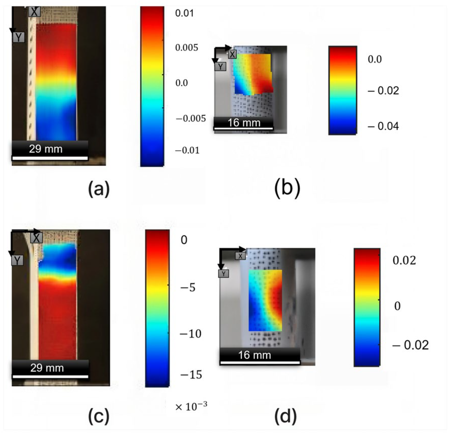
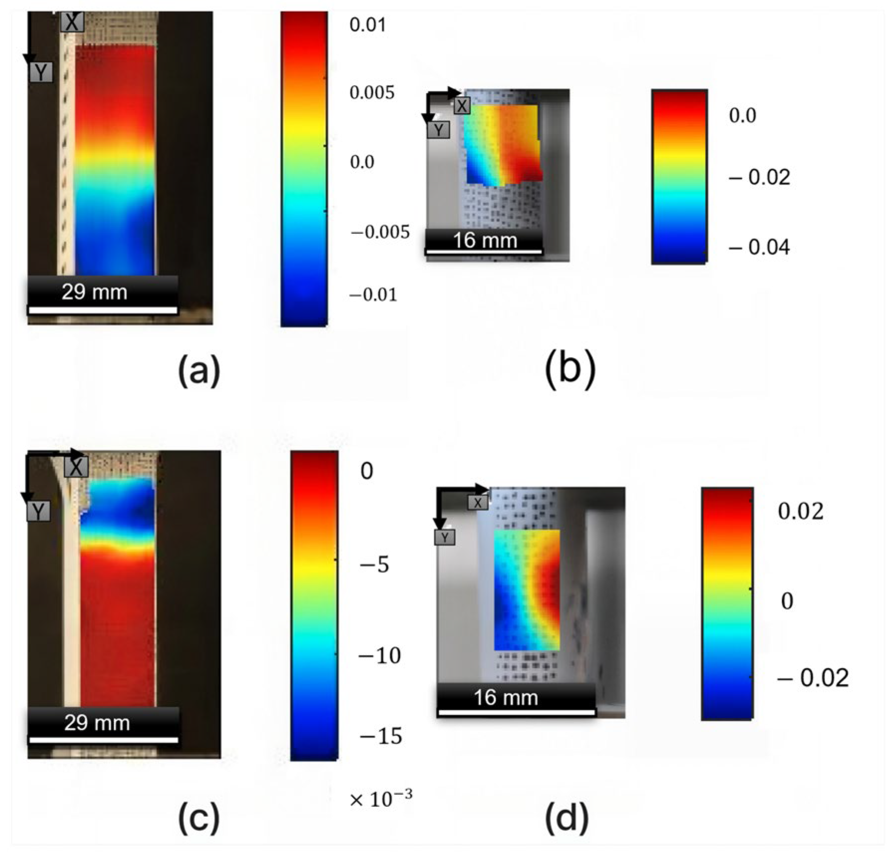
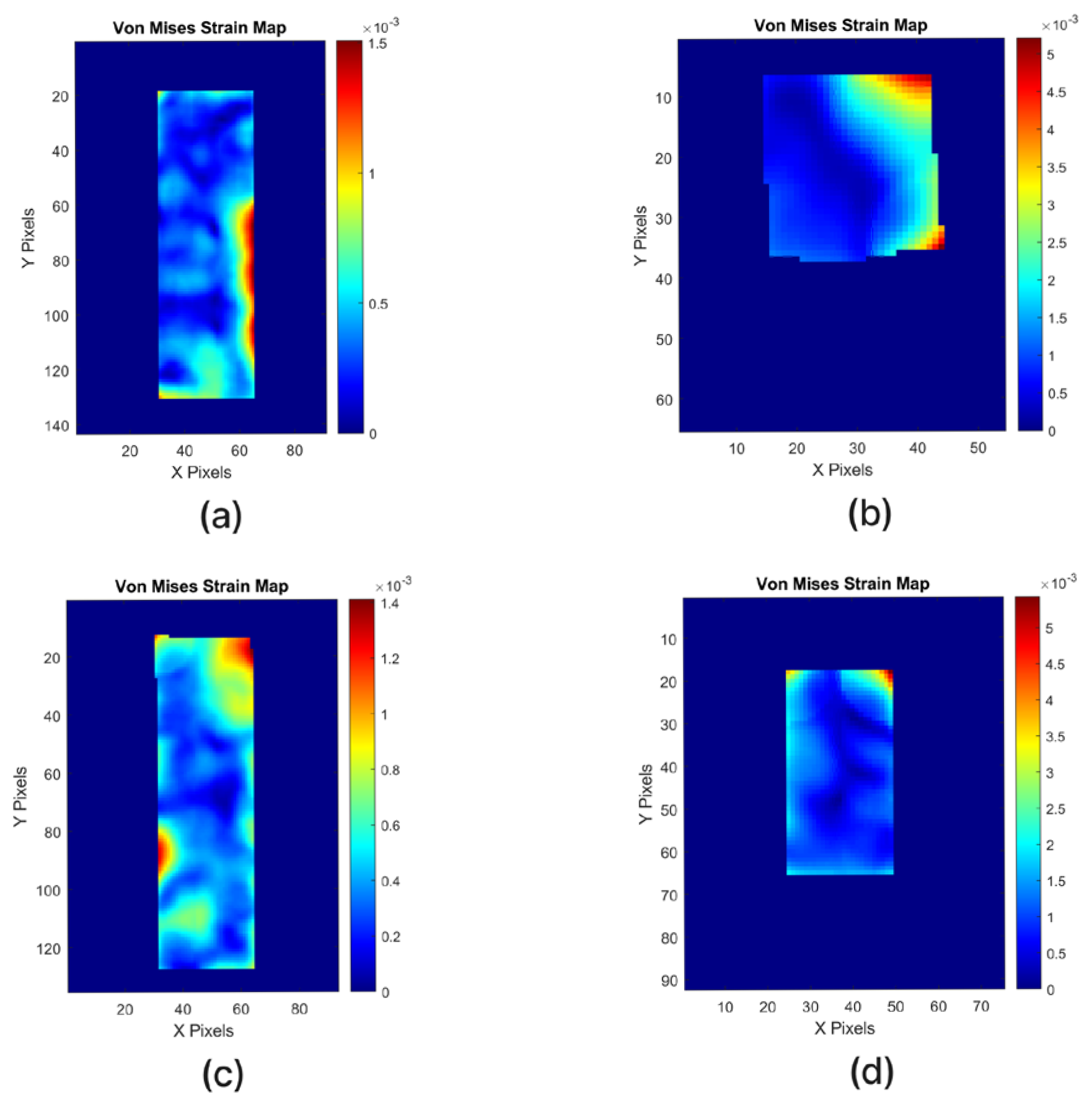
3.5. Tensile and Compression Strain Distribution via 2D-DIC
The 2D-DIC results clearly demonstrate the mechanical advantages of the bioinspired internal structure. To evaluate deformation behavior in greater detail, Digital Image Correlation (2D-DIC) was used to map local strain fields during both tensile and compressive tests.
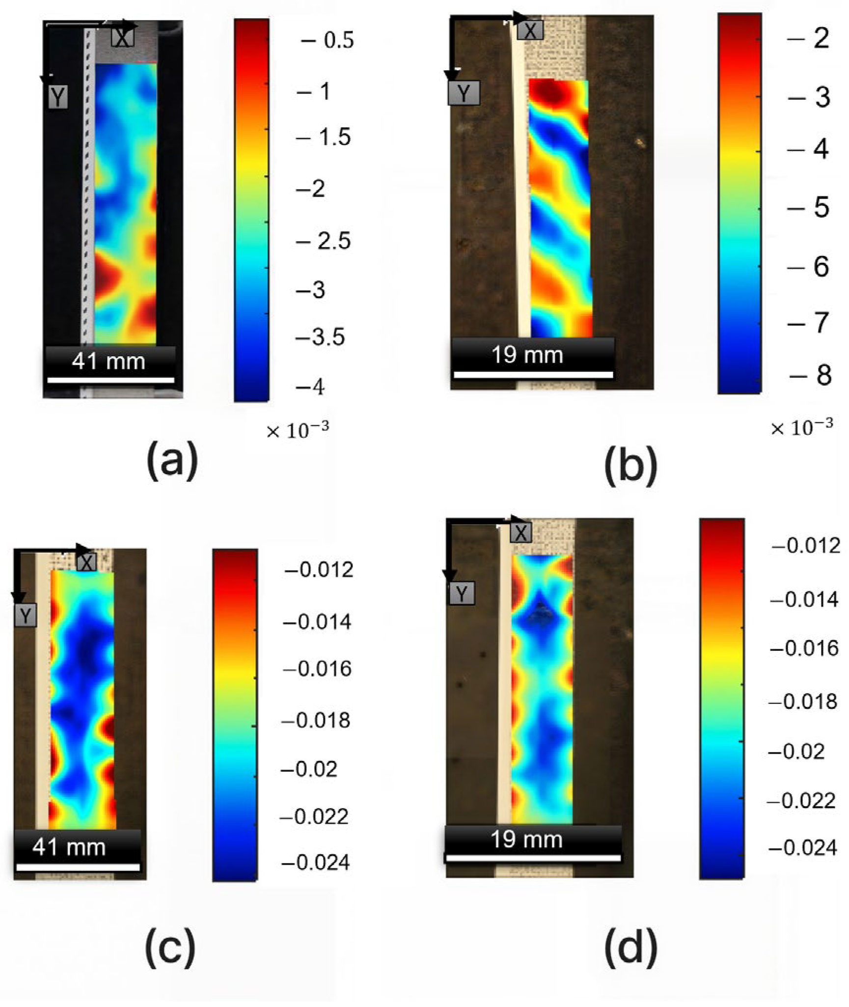
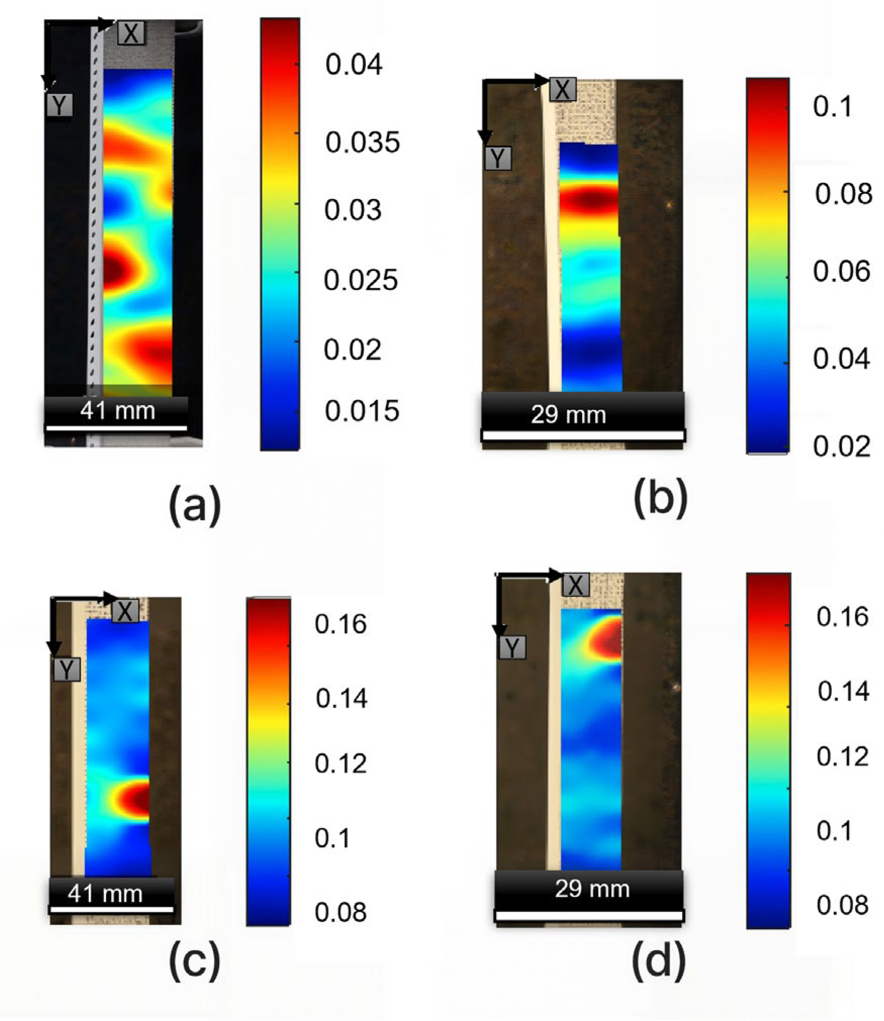
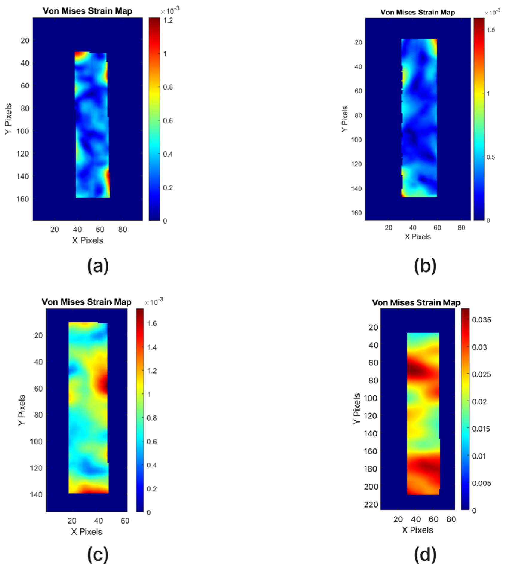
The complete strain field maps and contour distributions are provided in
Appendix A.
Under tensile loading, the bioinspired structured specimens exhibited significantly more uniform strain fields compared to the control samples. The CFC-structured design presented the lowest axial and von Mises strain values (εxx ≈ 3.8 × 10⁻³; von Mises ≈ 1.2 × 10⁻³), indicating efficient stress redistribution and delayed failure initiation.
In contrast, the control groups showed pronounced strain localization (up to 3.5 × 10
−2), reflecting early crack propagation and unstable deformation. These quantitative results, summarized in
Table 7, confirm that the layered design effectively minimizes stress concentration and enhances load transfer.
Under compressive loading, the same trend was observed (
Table 8). The structured specimens, particularly the CFC-structured configuration, exhibited lower shear and vertical strain magnitudes (ε
xᵧ ≈ 0.015; εᵧᵧ ≈ 0.009) and smoother strain distribution. Control specimens, especially ABS-control, developed highly localized regions of deformation, consistent with poor lateral confinement.
These observations verify that the hierarchical internal geometry redistributes compressive stresses, suppresses lateral expansion, and maintains structural stability during crushing.
Collectively, the 2D-DIC analysis provides quantitative confirmation that the bioinspired multilayer configuration ensures strain uniformity, reduces localization, and improves overall energy dissipation efficiency, in strong agreement with the mechanical test findings.
3.6. Combined Acoustic Emission Analysis and DIC Analysis of Failure Mechanisms in Tensile Test
To further investigate the underlying damage mechanisms, AE monitoring was conducted simultaneously with DIC during the tensile tests. This combined approach allowed for a direct correlation between the microscale damage activity captured by AE signals and the macroscale strain localization patterns revealed by DIC. Specifically, AE sensors continuously recorded waveform activity, from which amplitude and energy features were extracted. At the same time, a high-resolution DIC system tracked the full-field strain evolution on the specimen surface. The synchronized acquisition enabled identification of the onset of microcracking, fiber–matrix debonding, and other early damage events acoustically, while confirming their corresponding spatial manifestations as strain concentrations and localization zones in the DIC strain maps.
It should be noted, however, that this combined AE–DIC measurement was performed only for the tensile specimens. Due to the geometric and fixture limitations of the compression setup, it was not possible to mount the AE sensors before testing. As a result, AE monitoring could not be applied to the compression experiments, and the results presented here focus exclusively on the tensile samples.
The AE results provide further insight into the failure mechanisms of both the carbon-fiber composite (CFC) and ABS specimens under tensile loading.
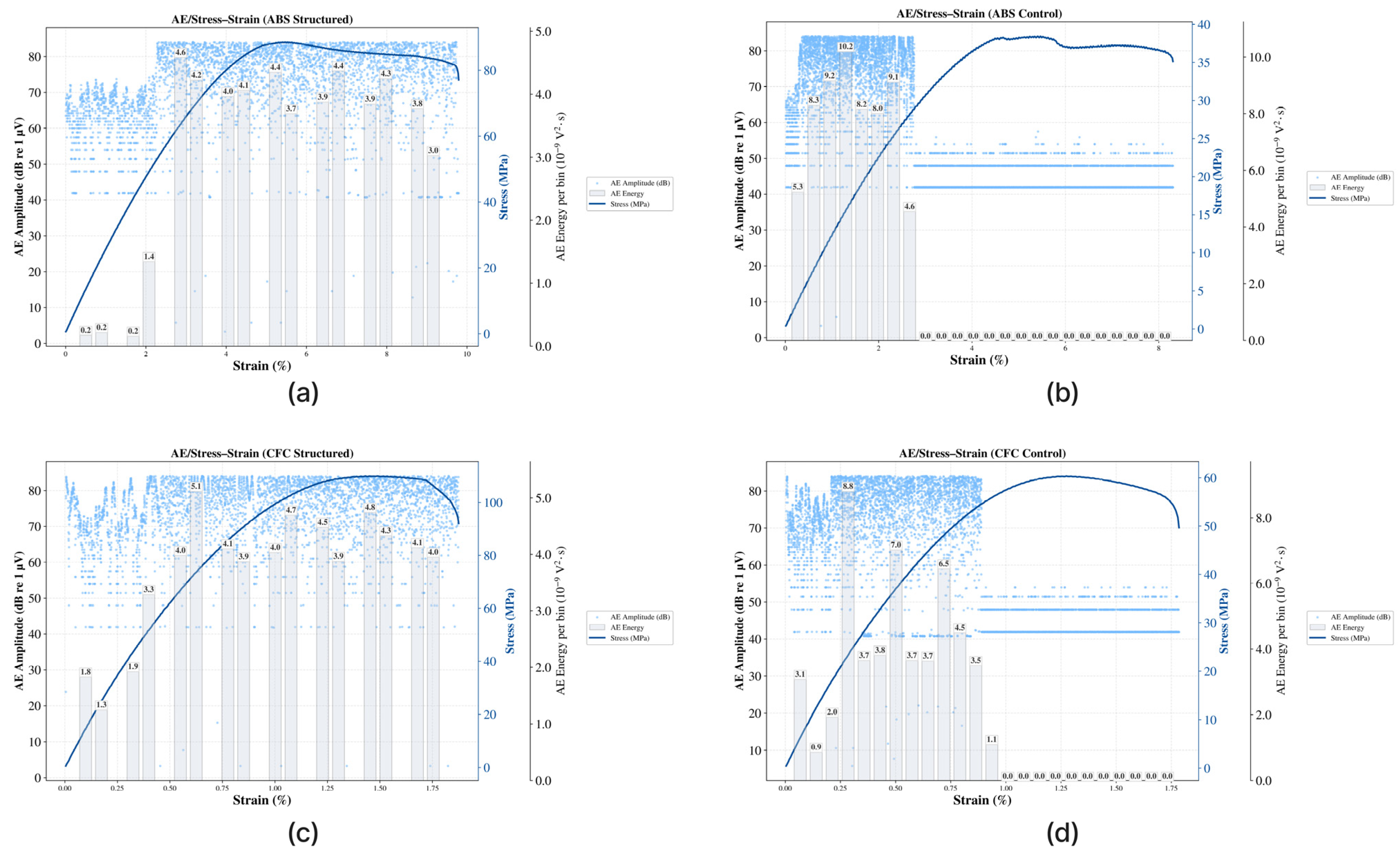
Figure 11 presents the evolution of AE amplitude, binned AE energy, and stress–strain responses for the structured and control configurations of each material.
The CFC-structured specimen demonstrated the highest strength, exceeding 110 MPa at strains of ~1.5–1.7%, accompanied by a dense distribution of AE events with amplitudes exceeding 70–80 dB. The corresponding binned AE energy was spread across the entire loading history, indicating a progressive and staged failure sequence where localized microcracking, fiber–matrix debonding, and subsequent structural collapse occurred in a controlled manner. In contrast, the CFC-control specimen failed at approximately 60 MPa, with AE activity highly concentrated in the early stages of loading (<1% strain). This localization of energy release reflects a more brittle failure mode, where damage accumulated rapidly without significant progressive mechanisms.
A similar trend was observed for the ABS specimens. The ABS-structured sample reached ~85 MPa at strains approaching 10%, outperforming the ABS-control specimen, which failed around 35–37 MPa. The structured design promoted a more ductile and tougher response, with AE events distributed over the full strain range, consistent with gradual crack propagation and energy absorption. By contrast, AE in the ABS-control sample was almost entirely confined to the initial 2–3% strain, followed by negligible activity, further confirming its brittle-like response.
A significant comparison arises between ABS-structured and CFC-control. Despite ABS being intrinsically weaker than CFC, the bioinspired structural design enabled ABS to achieve a higher ultimate strength (85 MPa vs. 60 MPa) and significantly greater ductility. This demonstrates that architectural design can compensate for the inherent material limitations and, in some cases, even surpass the performance of a stronger but unstructured counterpart.
The AE behavior also provides valuable insights into the Kaiser and Felicity effects. In the Control specimens, early and concentrated AE activity suggested a deviation from the Kaiser effect, with significant acoustic responses appearing before the maximum prior stress was reached. This behavior reflects the Felicity effect, often associated with premature internal damage and unstable crack growth. Conversely, in the Structured specimens, AE events were more evenly distributed throughout the loading cycle and were primarily triggered at higher stress levels, more consistent with the Kaiser effect. This indicates a more stable damage evolution and a delayed onset of the Felicity effect, underscoring the structural integrity and robustness imparted by the bioinspired architecture.
Correlation of AE Data with DIC Strain Maps
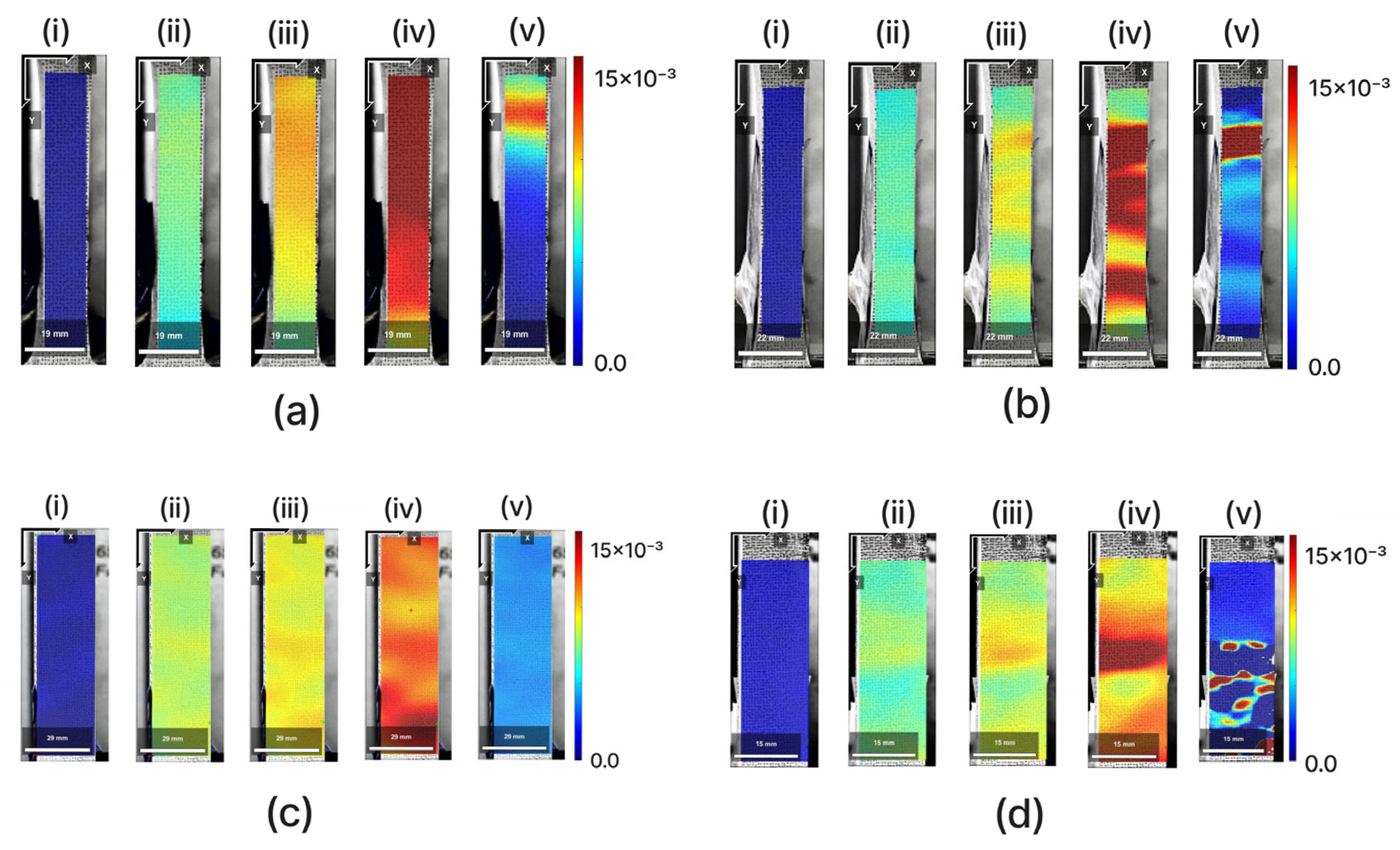
The full-field strain maps obtained from DIC provide direct visualization of strain localization patterns and strongly corroborate the gradual failure mechanisms inferred from the AE results. Representative frames from five loading stages (i–v) are presented in
Figure 12 for the CFC-structured, CFC-control, ABS-control, and ABS-structured specimens. These stages include: (i) onset of elastic deformation, (ii) early plasticity, (iii) strain localization, (iv) peak load, and (v) post-fracture stage.
For the CFC-structured specimen (
Figure 12c), the strain fields evolve gradually from a uniform distribution in the elastic regime (i) to localized bands in the intermediate stages (iii–iv), reflecting progressive fiber–matrix debonding and controlled microcrack development. In the post-fracture stage (v), high-strain red zones remain dispersed in clustered forms, indicating a gradual collapse and the avoidance of sudden catastrophic failure. This pattern is in direct agreement with the AE results, which revealed sustained event amplitudes and distributed energy release throughout the loading history.
In contrast, the CFC-control specimen (
Figure 12d) exhibits strain heterogeneity as early as stages (ii–iii), with intense red strain bands emerging near peak load (iv). The post-fracture stage (v) exhibits multiple concentrated high-strain zones, consistent with AE records that captured intense and localized bursts of energy, even before 1% strain, which is clearly indicative of a brittle and unstable damage mechanism.
The ABS-control specimen (
Figure 12b) also follows a brittle-like trend: strain distribution remains uniform up to ~2–3% strain, after which broad and intense bands suddenly appear (iii–iv). In the post-fracture stage (v), highly localized strain zones dominate. This observation aligns with AE results, which showed early, concentrated energy release followed by negligible activity, confirming its brittle failure behavior.
In contrast, the ABS-structured specimen (
Figure 12a) demonstrates a much more ductile and tough response. The strain gradually spreads across the gauge length (ii–iii) and maintains a relatively uniform pattern up to the peak load (iv). Even in the post-fracture stage (v), strain localization remains more diffuse compared to the control. These features are consistent with AE results, which show sustained and distributed activity throughout the test, confirming a gradual energy absorption process.
Taken together, the combined AE and DIC interpretation provides a coherent picture of the failure mechanisms:
In structured specimens, AE energy release occurred in a progressive and distributed manner, accompanied by uniformly evolving strain maps.
In control specimens, AE events were clustered and concentrated, coinciding with abrupt and localized strain bands.
This complementary evidence confirms that the bioinspired structural design not only enhances mechanical strength but also guides damage evolution in a more stable and controlled manner.
4. Discussion and Future Work
This study presents a groundbreaking approach-a multilayered, horn-inspired battery frame fabricated through FDM using both ABS and CFC materials. This innovative design translates natural hierarchical structures into a structurally efficient and crashworthy protective enclosure for EV battery modules. Across all mechanical evaluations, tensile, compressive, impact, and full-field DIC, the bioinspired configuration consistently outperformed conventional controls, confirming that structural design can rival, and in some cases exceed, the role of material selection in dictating performance.
Tensile testing revealed that structural effects more than doubled (2.4 times) the load capacity of both ABS and CFC specimens, with the structured ABS samples even surpassing the performance of the CFC-controls. Compression results highlighted the stabilizing influence of the layered geometry, enabling both structured ABS and CFC to achieve peak loads nearly three times (approximately 2.7 times and 2.8, respectively) higher than their controls, again underscoring the ability of architecture to compensate for baseline material limitations. Izod impact results demonstrated that ductility is a critical parameter for dynamic loading. ABS, when enhanced with a bioinspired internal lattice, absorbed substantially more energy, over 23% of the impact energy, nearly twice as much as CFC, which was limited by brittle fracture. These findings collectively confirm that structural optimization is a dominant factor in enhancing crashworthiness.
Strain field measurements via 2D-DIC further established that the horn-inspired geometry improves stress redistribution, suppresses localized deformation, and delays catastrophic failure. Shear, transverse, and von Mises strain maps consistently showed smoother gradients and lower maxima in structured designs compared to controls, validating the efficiency of hierarchical architecture in managing multi-axial stress states. Complementary AE monitoring during tensile testing enriched this interpretation by linking distributed, progressive AE activity to gradual strain localization patterns in structured samples, in contrast to the abrupt, high-energy bursts observed in controls. The co-evolution of AE and DIC thus confirmed the presence of staged failure mechanisms, outer shell cracking, tubular buckling, and lattice collapse, that mimic the protective strategy of natural horns. Importantly, structured specimens largely preserved the Kaiser effect, demonstrating stable damage progression and delaying the onset of Felicity, a hallmark of premature failure.
Taken together, these results underscore three central insights: (i) hierarchical architecture can provide mechanical robustness beyond what is achievable with material choice alone, (ii) ductility and staged failure are critical for impact-resistant energy storage enclosures, and (iii) combined AE–DIC monitoring offers a powerful diagnostic approach for unraveling the complex interplay between microscale damage events and macroscale structural response. The demonstrated ability of bioinspired frames to enhance load-bearing capacity, maintain post-peak stability, and dissipate impact energy positions them as promising candidates for next-generation EV battery protection systems.
Future research should extend this work by exploring additional material systems, scaling full-module prototypes, and evaluating performance under real crash scenarios, including dynamic and thermal-mechanical coupling. Nevertheless, the present findings already highlight the transformative potential of biomimetic design strategies in advancing EV safety. By embedding nature’s time-tested principles into engineered enclosures, it becomes possible to achieve lightweight, resilient, and reliable protection for LIBs, thereby contributing directly to the safer and more sustainable deployment of electric mobility. This transformative potential should excite and motivate researchers and professionals in the field.
Although this study employed a comprehensive suite of experimental methods, several avenues urgently need to be explored to further strengthen and expand the findings. A key next step is to broaden the scope of mechanical evaluation beyond quasi-static conditions. Fatigue testing under cyclic loading would provide critical insight into the long-term durability and damage accumulation of bioinspired architectures, which is particularly relevant for the repeated stresses encountered during the service life of EVs.
Another important direction is scaling from coupon-level specimens to complete battery modules. While the present investigation focused on standardized test coupons, future research should integrate bioinspired frames into module- or pack-level enclosures. Full-scale drop, penetration, and crash simulations would reveal the dynamic performance of multilayered designs under realistic collision scenarios, offering a more accurate assessment of their protective capacity in operational environments.
The material-specific findings of this study underscore the potential of hybrid frameworks. ABS demonstrated superior ductility and impact absorption, while CFC offered greater stiffness and peak strength. The strategic combination of these attributes in hybrid structures could lead to the development of lightweight yet crash-tolerant enclosures that effectively balance strength and energy dissipation.
Finally, incorporating high-fidelity finite element analysis (FEA) is strongly recommended as a complementary approach. Advanced numerical models can predict strain distributions, identify critical failure zones, and simulate extreme load cases, including high-velocity impacts and side collisions, where experimental reproduction is costly or impractical. This comprehensive understanding will guide future research and development in this field.
