Abstract
Lithium-ion battery (LIB) wireless charging using inductive power transfer (IPT) represents a transformative pathway for transportation electrification. While applications in railway systems remain limited, early studies highlight significant promises for implementation. This paper presents a hybrid energy-supply framework integrating LIB, inductive battery charging (BC) charging, and battery swapping (BS) to support a 20 km heritage trolley excursion between Belmont and Gastonia, NC. A kinematic simulation was developed to estimate traction energy demand, yielding 56 kWh per trip, or 112 kWh for two daily round trips. Finite element analysis (FEA) was conducted to design an LCL-s compensated 3 kW IPT system. Two transmitter configurations were evaluated: W–I ferrite cores (peak coupling ~0.22) and magnetic concrete slabs (~0.20). Although ferrite offers higher efficiency, magnetic concrete demonstrates superior durability and integration potential. Simulation results indicate that wireless charging alone, whether static or dynamic, is insufficient; similarly, a single daily BS strategy provides only 96 kWh. Seven BC-BS hybridization scenarios were evaluated, showing that mid-day swaps combined with either static or dynamic IPT produce a 12–16 kWh surplus. The most practical approach is a one-pack swap supplemented by uniformly distributed static pads, providing energy neutrality. This hybrid pathway ensures operational sufficiency, structural resilience, and compatibility with heritage rail preservation.
1. Introduction
1.1. Motivation
Transportation electrification is an important part of decarbonization for a more sustainable environment, and the most recent technology drive comes from LIB-equipped vehicles such as battery electric vehicles (BEVs), hybrid electric vehicles (HEVs), and fuel cell vehicles (FCVs) [1,2]. More recently, battery locomotives (battery/zero emission) technologies, albeit in the early stages of adoption by different agencies such as SBCTA, CPKC, Siera Northern, etc., have been gaining popularity [3].
An appropriately sized power supply is critical to proper rail vehicle operations; this includes route planning, train loading, and the stop–go scenarios [4]. Additional factors such as wheel-track friction, track-vehicle dynamics, multiple-bogie interactions and energy storage, etc., can all be critical [5,6]. From a control perspective, the onboard battery management system (BMS) and train control should be integrated for optimal system management [7].
LIB wireless charging without stopping using the IPT technology is a game changer for transportation electrification [8,9]. Although there have been few attempts to create designs at the system level using IPT systems for battery trains, most studies showed the great potential of technology implementation for rail electrification [10,11,12].
In this paper, a power supply analysis is performed on a historical trolley modified for 20 km long excursion through the historical sites of textile country in Gaston County, North Carolina. Because of the lack of an overhead powerline, the trolley has been modified to have a two-behind battery system, functionally equivalent to an LIB-powered locomotive. The power supply analysis of the trolley run indicated a need to have intermittent power charging in order to complete two round trips in a day. A hybrid power supply that combines wireless battery charging (BC) and battery swapping (BS) is deemed necessary to ensure a successful one-day scheduled trolley run. The following sections describe the different technologies developed for the sustained power supply of the battery trolley.
1.2. Dynamic Wireless Power Transfer: Technological Foundations
Dynamic Wireless Power Transfer (DWPT) technology has emerged as a transformative solution to address the inherent limitations of battery-dependent electric transportation systems [13,14]. Unlike conventional plug-in charging systems that require vehicles to remain stationary during energy replenishment, DWPT enables continuous power transmission to moving vehicles through electromagnetic induction, fundamentally altering the paradigm of electric vehicle operation [15,16].
The theoretical foundation of DWPT systems is based on Faraday’s law of electromagnetic induction, where alternating current flowing through transmitter coils embedded in infrastructure creates time-varying magnetic fields that induce currents in receiver coils in adjacent objects; for the rail industry, this includes track-mounted induction system that can power receiver-equipped rail vehicles [17,18]. This contactless power transmission mechanism offers several compelling advantages: a significant reduction in required onboard battery capacity (up to 70% in some applications), elimination of charging downtime, an extended operational range, and reduced total cost of ownership [19,20].
Recent technological advances have demonstrated remarkable improvements in DWPT system performance. State-of-the-art implementations achieve power transfer efficiencies exceeding 95% under optimal alignment conditions, with some systems maintaining over 85% efficiency even under significant lateral misalignment scenarios [21,22]. These efficiency gains result from sophisticated coil design optimization, advanced compensation circuit topologies, and innovative magnetic core materials that enhance electromagnetic coupling while minimizing losses [23,24].
1.3. Magnetic Core Material Selections for DWPT Systems
1.3.1. Ferrite Cores
Traditional DWPT systems predominantly employ ferrite materials as magnetic cores due to their exceptional electromagnetic properties at high frequencies [25,26]. Ferrite cores, typically composed of iron oxide combined with other metallic elements, exhibit high magnetic permeability (μr = 1000–5000), low electrical conductivity, and minimal eddy current losses at operating frequencies between 20 and 200 kHz [27,28]. These characteristics enable efficient magnetic flux concentration and coupling between transmitter and receiver coils.
Recent research has identified optimal ferrite core configurations for various DWPT applications. U-shaped ferrite cores paired at primary and secondary sides demonstrate superior performance, achieving 94.69% efficiency in finite element simulations and 89.7% in experimental validation under realistic operating conditions [29]. Central bulge ferrite core designs offer an enhanced performance compared to planar configurations, maintaining high efficiency even under extended power transfer distances and lateral misalignment conditions [30].
However, ferrite materials present several limitations that constrain their application in large-scale DWPT infrastructure. These include mechanical brittleness, temperature sensitivity (with a typical Curie temperature of 100–300 °C), high material costs for large installations, and complex manufacturing requirements for custom geometries [31,32]. Additionally, ferrite cores are susceptible to mechanical stress and environmental degradation, potentially limiting their long-term reliability in harsh transportation environments [33]. Furthermore, for the rail industry, the implementation requirements should not result in unwittingly electrifying large portion of the rail when the inductor is operational; thus, isolated/insulated sections of track may be necessary.
1.3.2. Magnetic Concrete: An Emerging Alternative
Magnetic concrete has emerged as a promising alternative to traditional ferrite cores, offering the potential to integrate DWPT functionality directly into transportation infrastructure [34,35]. This innovative material combines the structural properties of conventional concrete with magnetic characteristics achieved through the incorporation of magnetic particles, including magnetite (Fe3O4), ferrite powders, or other magnetic aggregates [36,37].
The development of magnetic concrete addresses several critical limitations of ferrite-based systems. By embedding magnetic properties within structural elements, magnetic concrete enables seamless integration of DWPT infrastructure into roadways, railway tracks, and parking facilities without requiring additional installation space or complex mounting systems [38,39]. This approach potentially reduces installation costs, improves system durability, and simplifies maintenance procedures [40,41].
Recent investigations into magnetic concrete formulations have demonstrated promising electromagnetic properties. Optimized mixtures incorporating 15–25% magnetite content by weight achieve relative permeabilities ranging from 2 to 8, higher than conventional concrete (μr ≈ 1), while maintaining adequate mechanical strength for structural applications [42,43]. Advanced formulations utilizing ferrite nanoparticles have achieved even higher magnetic permeabilities (μr = 10–15) with minimal impact on compressive strength [44,45].
1.4. Current Challenges and Research Gaps
Despite technological progress, several critical challenges continue to limit the widespread deployment of DWPT systems in transportation applications. For example, electromagnetic interference (EMI) remains a primary concern for DWPT system deployment, particularly in sensitive environments such as airports, hospitals, and urban areas with dense electronic infrastructure [46,47]. DWPT systems operating at high power levels (>10 kW) generate significant electromagnetic fields that may interfere with communication systems, medical devices, and other electronic equipment [48,49]. Current international standards, including IEC 61980 and SAE J2954, provide guidelines for EMI limits, but implementation challenges persist in real-world applications [50,51].
Advanced shielding strategies have been developed to mitigate EMI concerns, including metamaterial-based shields, ferrite–nanocrystalline hybrid shielding methods, and active cancelation techniques [52,53]. Research demonstrates that T-shaped metamaterial configurations can enhance power transfer efficiency by 7.7% while simultaneously reducing electromagnetic emissions [54]. However, these solutions often increase system complexity and cost, limiting their practical implementation [55].
Maintaining efficient power transfer under dynamic conditions with varying vehicle speeds, lateral displacement, and vertical airgaps presents significant technical challenges [56,57]. Real-world DWPT applications must accommodate misalignment tolerances of ±200 mm laterally and airgaps ranging from 100 to 300 mm to ensure practical operation across diverse vehicle types and road conditions [58,59].
Advanced coil designs, including double-D and bipolar pad configurations, have been developed to improve misalignment tolerance [60]. Quadruple-D compensation coil systems demonstrate promise, maintaining high efficiency across extended misalignment ranges while providing compact system integration [61]. However, these advanced designs often require complex control systems and precise manufacturing tolerances, increasing implementation costs [62].
The lack of standardized DWPT infrastructure specifications hinders large-scale deployment across different manufacturers and regions, but offers opportunity for future research [63]. Current systems often employ proprietary coil designs, operating frequencies, and communication protocols, limiting interoperability and increasing deployment costs [64,65]. International standardization efforts, including ISO 19363 and IEC 61980 series, are progressing but remain incomplete for many application scenarios [66,67].
Relevant to current application to heritage railways, the application of DWPT technology presents a distinctive set of technical challenges [68]. When operating historical locomotives and rolling stock, it is necessary to balance modern safety and efficiency requirements with strict preservation mandates that limit modifications to original equipment [69]. As such, traditional electrification approaches, such as overhead catenary systems or third rail configurations, are often incompatible with heritage railway operations due to aesthetic concerns, safety requirements, and infrastructure constraints [70]. Hence, DWPT technology offers a potential solution by enabling electrification without visible overhead infrastructure or track-level electrical hazards [71].
1.5. Belmont Trolley Restoration Project and the LIB Trailer
The Belmont Trolley restoration project in North Carolina exemplifies these aforementioned challenges, in which a 1904 historical streetcar required modernization with contemporary power systems while maintaining authentic heritage appearance. Similar projects worldwide have faced similar constraints, including limited space for battery installation, weight restrictions, and the need for reversible modifications that preserve historical integrity [72]. In the Belmont Trolley case, the modernization strategy considered the construction of an LIB trailer car with wireless power charging to satisfy the intended supplemental energy while maintaining aesthetic requirements and vehicle integrity.
Recent comparative studies between battery swapping and wireless charging highlight the complementary nature of these technologies in transportation electrification. While DWPT provides continuous energy transfer and reduces the dependency on oversized onboard batteries, battery swapping enables near-instantaneous replenishment of energy reserves by replacing depleted modules with fully charged units [73,74]. This dual approach is particularly advantageous for heritage railways, where minimizing modifications to rolling stock is critical. Battery swapping allows heavy battery systems to be installed on auxiliary cars or offboard facilities, while DWPT reduces operational downtime by extending runtime between swaps.
From an infrastructure perspective, swapping stations demand standardized battery modules, robotic handling systems, and inventory management, whereas DWPT requires embedded coils and alignment-sensitive power pads [73]. Though both approaches carry significant cost implications, hybridization can balance these trade-offs: DWPT reduces the number of swaps needed during operation, and swapping ensures reliable energy availability during longer stretches of travel where DWPT coverage is limited. This synergy provides a pragmatic pathway to decarbonize heritage rail operations without compromising cultural preservation or passenger safety. In case of battery system failure, the passengers can disembark to an adjacent facility while a recovery/alternate travel plan is confirmed.
1.6. Research Objectives
In this paper, an IPT system has been developed for a historical trolley car, Car No. 1 (built in 1904 by J.G. Brill Co., Philadelphia, PA, USA), which is intended to traverse the historical textile mills between Belmont, NC, and Gastonia, NC. Shown in Figure 1, Car No. 1 was originally powered by 500–550 Vdc overhead power lines. With the removal of the catenary infrastructure, a trailer car has been repurposed to house an LIB pack, enabling operation of the trolley along a 20 km route in Gaston County, NC, USA.
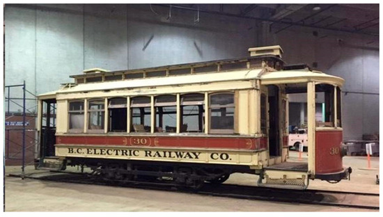
Figure 1.
Trolley Car No. 1 to be retrofitted for Belmont—Gastonia route run.
Figure 2 The 20 km Belmont–Gastonia route passes through Belmont, Mount Holly, Cramerton, McAdenville, Lowell, Ranlo, and ends in Gastonia. Twelve evenly spaced train stops were assumed for analysis. The orange line indicates the trolley route and the color shading (red to blue, scale in feet) shows elevation. The lower plot illustrates the velocity profile with periodic acceleration and deceleration at the 12 stops. An inset map of North Carolina highlights the study area.
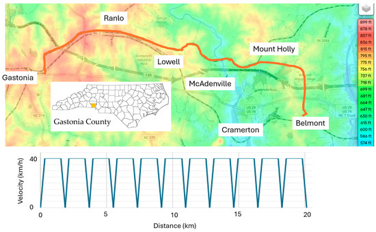
Figure 2.
Major cities along the Belmont–Gastonia route and the planned travel velocities between 12 train stops.
The trailer car repurposed to accommodate the battery system is presented in Figure 3, where a Nissan Leaf battery pack was installed to provide traction power to the trolley. Figure 3a illustrates the major power electronic components in the LIB trailer car, including the inverter, charger, and controller. Figure 3b presents the conceptual arrangement of wireless power charging applied to the LIB trailer car during motion. In case of battery fire, to ensure safety to the passengers, the LIB trailer car can be disengaged from the trolley and remotely drive away from the trolley.
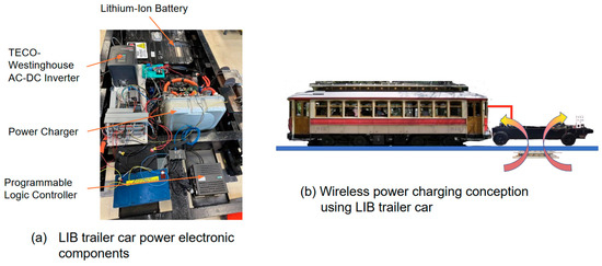
Figure 3.
The Lithium-ion battery trailer car design: (a) LIB trailer car power electronic components and (b) wireless power charging conception using the LIB trailer car.
The electric configuration of Car No. 1 is presented in Figure 4. The vehicle is equipped with twin D-K motors driving the front and rear bogie axles, with power supplied from the LIB through an IPT system embedded between the rails. A kinematic simulation of the 20 km route was performed, and the analysis determined that the total energy requirement for Car No. 1 is approximately 56 kWh.

Figure 4.
General equipment arrangement for the DC electric locomotive with wireless power transfer and LIB.
This study represents a first in using LIB technology to power a historical trolley, which has the potential of extending the useable lives of several such locomotives around the world. The scientific contribution of the current paper is to demonstrate the power consumption calculation for the LIB trolley trailer and the use of hybridization of BC and BS technologies to help extend the surplus power for the Belmont–Gastonia excursion.
Figure 5 shows the prototype of transmitter pads evaluated in this study. A cast magnetic concrete slab pad in the foreground and a modular W–I shaped ferrite cores in the middle ground, both carrying a transmitter coil with the same inductance. These prototypes correspond to the two transmitter material options that are modeled and compared later and implement the three-segment transmitter/single-receiver architecture operated at 85 kHz with a 12.7 cm airgap and a 3 kW power rating.
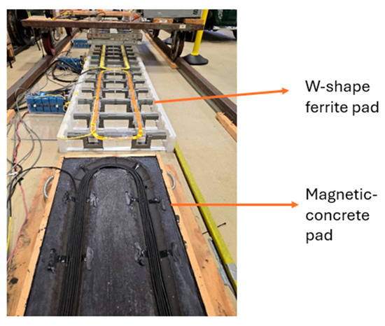
Figure 5.
Magnetic concrete pad with W–I shaped ferrite pads used in the DWPT prototype testbed.
The following sections present the methodology in detail, beginning with route planning and power demand analysis, followed by a detailed analysis of IPT transmitter pad designs. Different magnetic materials and charging strategies are evaluated under different operational scenarios to assess feasibility and performance.
2. Route Planning for Trolley Car No. 1
2.1. Energy Utilization Kinematic Analysis
The kinematic analysis of the 20 km run between Belmont, NC, USA and Gastonia, NC, USA with 12 intermediate stops was carried out under the assumption that physics-based algorithms can approximate actual train energy consumption with reasonable accuracy [75]. The analysis is based on the Lomonossoff equation of motion:
where is the vehicle mass in tons, is the total tractive effort, is the resistance to motion, is gravitational acceleration, is the track gradient, and is the velocity. The tractive effort is constrained by the adhesion force between the wheel and rail, expressed as follows [76]:
where is the friction coefficient and is the axle load. The total resistance to motion is modeled as
where , , , and are resistance coefficients and is the track curvature.
To evaluate the energy consumption, runtime, and power requirements for the Belmont–Gastonia run, a MATLAB R2022a-based kinematic simulation was performed. Figure 6 shows the results of kinetic energy, potential energy, traction energy, and work performed against resistance for the route. Energy consumption increases linearly with distance, with pronounced peaks during acceleration phases after each stop. The altitude and time profile are shown in Figure 7. The distance–time profile of the route is shown in Figure 8. While the altitude variations along the 20 km route are relatively modest, they contribute to gravitational resistance and influence the overall energy demand.
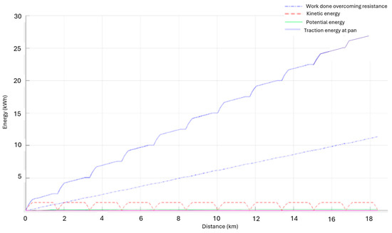
Figure 6.
Energy use for the 20 km route, assuming 12 train stops with 12 min of rest at each station and stop.
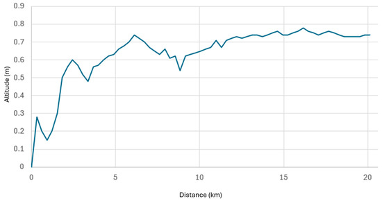
Figure 7.
General altitude changes in the rail structure from Belmont to Gastonia.
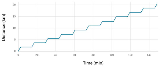
Figure 8.
Run time in minutes for the Belmont–Gastonia route with 12 min rest at 12 train stops.
The total energy requirement per one-way run was compared to the capacity of the 40 kWh Nissan Leaf battery pack, as summarized in Table 1. For a 70-ton car mass (Table 2) with 30 passengers and a maximum traction force of 40 kN, the energy consumption was calculated as 28 kWh. This confirms that a single battery pack is sufficient for a one-way trip from Belmont to Gastonia.

Table 1.
Nissan battery specifications.

Table 2.
STS battery car route simulation parameters used in the design of the Belmont Trolley Route.
Based on these results, a single battery design cannot support a full round trip from Belmont to Gastonia and back, which would require 56 kWh of energy. To address this limitation, the trailer car was modified to carry two LIB packs, as shown in Figure 9. As a safety measure, between the two battery packs, there was a gap of 50 mm, which allowed the insertion of computer fans for the cooling off the LIBs. The brakes of the trailer car have electric deployments that can lock the wheels in case of a battery fire. An alternative solution would be to implement a battery swap at the Gastonia station. Further analysis is presented in the next section to evaluate realistic daily operation scenarios with two installed batteries.
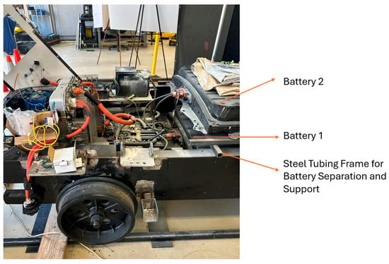
Figure 9.
Trailer car modified to carry two LIBs.
2.2. Energy and Battery Use Analysis
The total daily energy use was evaluated assuming two round trips per day, corresponding to a total operation time of 10 h and 41 min. Each round trip requires approximately 5 h and 14 min, with 13 min between trips. Starting at 8:00 a.m., the first trip concludes around 1:00 p.m., while the final return to Belmont occurs at 6:40 p.m. The daily operating schedule is shown in Figure 10.
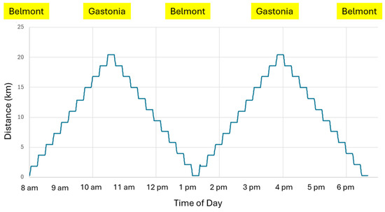
Figure 10.
The Belmont–Gastonia one-day trip scheduled from 8 am to 6:40 pm.
For one round trip, the energy requirement is 56 kWh (28 kWh per one-way trip). Assuming the batteries are charged to 80% of their total 80 kWh capacity (64 kWh usable), the system retains 8 kWh of reserve after a round trip, which corresponds to the minimum recommended reserve capacity for the Nissan Leaf batteries. Consequently, supplemental charging during daily operation is necessary. Since charging can be implemented using either static or dynamic IPT (DIPT) systems with varying efficiencies and costs, it is essential to first introduce the IPT transmitter design.
3. IPT Transmitter Designs
This section describes the primary side (transmitter) designs evaluated for the Belmont trolley DIPT system. In the design, a three-segment transmitter/single receiver architecture was used that operated with LCL compensation on the primary to limit reactive power flow to the inverter. The design objective is twofold: (1) achieve a high and spatially flat coupling coefficient k over the segment length to stabilize efficiency and power transfer, and (2) ensure that the hardware is compatible with rail infrastructure constraints and heritage vehicle integration needs described earlier.
Two transmitter pad material systems are compared:
- A W-I shaped ferrite cores array.
- A magnetic concrete slab.
In both cases, a single rectangular receiver (Rx) loop mounted beneath the trolley car traverses the three primary segments (Tx-1 to Tx-3). The three transmitter coils can be energized individually or in overlapping pairs during hand-off. Conceptual layouts for both material systems are shown in Figure 11, and the principal pad dimensions are summarized in Figure 12.

Figure 11.
Transmitter pad configurations for DIPT system. (a) W-I shaped ferrite cores with Litz wire; (b) magnetic concrete with Litz wire.

Figure 12.
Dimensions of IPT transmitter pad configurations. (a) W-I shaped ferrite cores structure with Litz wire; (b) magnetic concrete structure with Litz wire.
3.1. Electromagnetic Modeling Workflow
All electromagnetic calculations are carried out in Ansys Maxwell 3D. For each material system, a parametric sweep is performed with the Rx translated along the track centerline across the three-segment assembly (from −250 cm to +250 cm in 10 cm increments). At each position x, the solver returns the self-inductances and , and the mutual inductances between the Rx and each transmitter coil The position-dependent coupling for each pair is then calculated by
When two adjacent segments are simultaneously excited during a hand-off, the effective coupling experienced by the Rx is approximated by a current-weighted sum , where captures the commanded current ratio of the active segments. For equal per-segment currents , closely follows the purple “Total k” traces reported in Figure 13 and Figure 14.
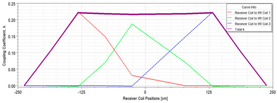
Figure 13.
Coupling coefficient k between the receiver coil and transmitter coils in the W-I shaped ferrite cores configuration.
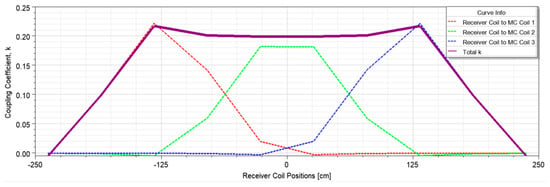
Figure 14.
Coupling coefficient k between the receiver coil and transmitter coils in the magnetic concrete configuration.
The choice of k as the principal design metric is deliberate. In a tuned high-Q LCL-s IPT link with constant-current excitation, both transferred power and link efficiency increase monotonically with (all else being equal). Hence, shaping to be high and flat directly supports constant-power operation and simplifies power-flow control during motion, criteria that will be used in Section 4 for route-level decision making.
3.2. Coil Geometry and Materials
The three Tx segments are identical in terms of their footprint and electrical design; segment centers are spaced so that the rising flank of one segment’s overlaps the falling flank of its neighbor, creating a “flat-top” aggregated when two segments are co-energized in the overlap region.
- W–I ferrite design (Figure 12a): the Litz loop is supported by alternating W–I-shaped ferrite cores to concentrate flux and to provide lateral shielding toward the rails. The effective pad footprint is approximately 107.4 cm (length) × 50.8 cm (width) with a ferrite core height of 8.25 cm.
- Magnetic concrete design (Figure 12b): a solid magnetic concrete slab (thickness ≈ 8.9 cm) houses the identical Litz loop. The slab footprint is approximately 115 cm × 38 cm.
Both designs were tested with a consistent airgap of 12.7 cm between the transmitter and receiver coils, at an operating frequency of 85 kHz, and delivering an output power of 3 kW. For rail vehicles, the standard clearance requirement is 50.8 mm above the top of the rail (TOR). Hence, both designs maintain the same airgap and Rx geometry in simulation to enable a fair comparison.
The W–I ferrite core is constructed using 3C90 material, which has a magnetic permeability of 2300, while the magnetic concrete exhibits a permeability of 18. The transmitters feature identical copper winding inductance for both types of couplers, and the same applies to the receivers. These settings ensure that the observed differences in ) arise primarily from field-shaping by the core medium rather than from winding choices.
3.3. Three-Segment Layout and Handover Strategy
As shown in, the 3-/1- topology indicated that as the trolley advances, the active segment set ) changes according to the spatial location of the :
- Single-segment zones: away from boundaries, a single is energized (e.g., -2 when the is near segment center).
- Overlap zones: near the midpoints between segment centers, two neighboring segments (e.g., -1 and -2) are co-energized. Commanded current ratios are linearly ramped between the two segments so that remains as constant as possible across the hand-off.
3.4. Coupling Coefficient Results
The simulated position-dependent couplings are plotted in Figure 13 (ferrite) and Figure 14 (magnetic concrete). In each figure, dashed colored lines give segment for the three segments; the purple solid curve shows the aggregated with equal per-segment currents in overlap regions.
- W–I ferrite design (Figure 13): Each individual segment exhibits a near-triangular segment with a peak around 0.22–0.23, and the aggregated coupling maintains a flat plateau near ≈ 0.22 which roughly ramps down linearly as the leaves the three-segment assembly.
- Magnetic concrete design (Figure 14): Due to the lower relative permeability of magnetic concrete, the peaks of segment are modestly reduced. The aggregated remains high and nearly constant around 0.20 across the same travel span, with slight convexity (mild dips at the center and small rises near the edges) that can be compensated in control by modest current re-weighting during hand-off.
The key outcome is that both material systems achieve a wide flat-top over ~2.5 segment lengths, enabling constant-power operation along most of the pad while the vehicle is in motion. The ferrite array delivers ~10% higher peak k than the magnetic concrete slab, while the magnetic concrete slab offers simpler civil integration and improved robustness against mechanical damage.
3.5. Implications for Power Transfer and Control
In a resonant LCL-s IPT link, the dc power at the rectified Rx side scales approximately as (neglecting the parasitic aspect), and the link efficiency improves with increasing because copper and core losses do not rise as fast as the mutual term for a fixed current envelope. Consequently, the flat achieved by the three-segment layout directly translates into a spatially uniform power capability with minimal converter re-tuning during motion. In the overlap regions, the distributing current between two neighboring segments keeps nearly constant while reducing the current stress on each segment and smoothing the input impedance seen by the primary inverter.
For routing and dynamic charging integration (Section 4), the curves in Figure 13 and Figure 14 constitute a look-up table that maps vehicle position to available coupling—and therefore to available power for a given current limit. This allows the placement of energized segments at locations where the route energy model predicts deficits, and the selection of hand-off points that guarantee continuous power delivery without efficiency dips.
4. Routing and Charging Scenario Integration
The decision making in the IPT system placement is critically dependent on the power usage of the trolley during operation. In the current study, we consider two different power charging strategies: (1) static charging only and (2) dynamic charging only. These scenarios, along with battery swapping, resulted in seven possible charging scenarios. Due to the critical constraints of the LIB car (with one battery stacked on top of another), battery swapping considers only one battery replacement and not both.
4.1. Planning Data and Decision Variables
The train kinematic analysis projected an energy use of 28 kWh per one-way under a 70-ton car, 30-passenger, 40 kN maximum traction setting. Operations were planned with 12 min dwell at each stop. The 12 min dwell is to accommodate disabled or mobility-challenged passengers. The battery trailer carried two Nissan Leaf LIBs, operated to 80% usable state of charge (SoC) (64 kWh) for battery longevity. These parameters govern charging strategy comparisons.
The position-coupling coefficient serves as the gating metric so that segments are energized only while the receiver occupies the high-k plateau, stabilizing power and minimizing reactive VA.
4.2. Charging Strategies and Scenario Definitions
From the two charging strategies, the use of different transmitter cores (magnetic concrete and ferrite material) and the routing and station setup, we further develop seven different power supply scenarios:
- Static charging using ferrite pads without battery swap (SC-F): only transmitters using W-shaped ferrite cores are used.
- Dynamic charging using ferrite pads without a battery swap (DC-F): several transmitters using W-shaped ferrite cores are used.
- Battery swapping without charging (BS): a battery swapping setup is installed at the Belmont Trolley station and no wireless power charging is used. No battery swapping takes place at Gastonia station.
- Static charging using ferrite pads with battery swap (SCBS-F): ferrite pad transmitters are used at all stops and the battery swap is performed at the Belmont Trolley station.
- Dynamic charging using ferrite pads with battery swap (DCBS-F): ferrite pads are installed along the tracks and the battery swap setup is installed at the Belmont Trolley station.
- Static Charging using magnetic concrete pads with battery swap (SCBS-M): magnetic concrete transmitters are used at all stops and the battery swap is performed at the Belmont Trolley station.
- Dynamic charging using magnetic concrete pads with battery swap (DCBS-M). ferrite pad transmitters are installed along the railroad tracks and the battery swap is performed at the Belmont Trolley station.
Scenarios where magnetic concrete-based transmitters are used for charging in combination without battery swap are ignored, as they will result in the smallest power supply.
Section 3 showed slightly lower k for magnetic concrete than for W-I ferrite under identical geometry. If pad rating is fixed by the inverter (e.g., 3 kW), the daily energy for magnetic concrete scenarios equals that for ferrite; at an equal coil current rather than equal rating, magnetic concrete requires modestly more length or current to achieve the same delivered power.
4.3. SoC Forecast and Segment Energization Logic
For routing and control, a simple predict-then-act loop is employed:
- Forecast energy use: From the kinematic model, compute energy for each inter-station leg . Summing these provides the one-way 28 kWh baseline used below.
- Map position to power: use the pre-characterized from Section 3 (flat ≈ 0.20 or 0.22 in overlap regions) to estimate instantaneous deliverable power along each candidate IPT segment.
- Determine time to energize: Before entering an IPT zone, compute the energy shortfall to the next reliable charging opportunityIf > 0, energize the zone and set currents so that remains on its flat plateau (by ramping adjacent coils as in Section 3). Otherwise, keep the zone switched off to minimize converter VA and stray fields.
- Compute the required dwell/length: For a static pad rated and dwell , the recoverable energy is . For a dynamic zone rated traversed at average speed v, the required energized length isHere, t is the charging time, and lower speed (e.g., immediately after departure) yields more energy per meter and is therefore preferred for siting dynamic segments.
4.4. Energy Accounting
Static and dynamic contribution follow operating time and rating. With static pads at all 12 stations, = 3 kW and = 0.2 h, the energy generated, Es, via static charging is
For dynamic charging at , the absolute upper bound is the energized time during the 10.68 h service window:
noting that practical is lower because not all track is instrumented or energized continuously. The daily balance, ΔE, for any scenario is, therefore,
with (no swap) and for a one-pack mid-day swap. A positive indicates surplus (feasible), while a negative indicates deficit (infeasible).
4.5. Results by Scenario (3 kW Pad Rating; One-Pack Swap)
Table 3 summarizes the daily contributions and the resulting deficit/surplus relative to .

Table 3.
Daily energy balance by scenario for a 3 kW pad rating. Two round trips/day, 12 min dwell at 12 stations per run.
5. Discussion
Under the demonstrated 3 kW pad rating, it is obvious that BC alone remains insufficient (SBC-F and DBC-F show deficits), and BS only with one-pack replacement is also insufficient (+16 kWh deficit). Hence, combining one-pack swap with either static or DIPT closes the day’s energy gap and provides the most reasonable operational margin.
There is much to say about the pad placement for dynamic charging: Ideally, the charging dynamic pads should be placed where vehicle speed is low (immediately after departure and on mild grades) to maximize energy per meter. Based on the -awareness results from Section 3, the coils should be energized only within the flat-top region and ramp adjacent-coil currents during hand-off to maintain near-constant power and a benign inverter operating point.
For the Belmont–Gastonia run, the dynamic charging system is assumed to be placed throughout the entire rail line. This is feasible because of the relatively low gradient in the region.
Figure 15 shows a summary of the proposed hybrid power charging technology for Car No. 1, and the following key observations have been made from the analysis carried out:
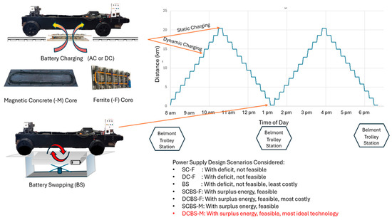
Figure 15.
Proposed technologies and analysis outcomes for Car No. 1 for a one-day excursion along the Belmont–Gastonia route showing positions of BC and BS technology implementations.
- The minimum infrastructure combination to reach energy-neutrality with one-pack swap with a uniform static pad rating is listed below, with Ps.min of ≈1.7 kW at all stations, which closes the residual 16 kWh gap, Egap:where Nstops is the number of stops and Nruns is the number of runs per day.
- Static + one-pack swap (SBCBS-F/M): a ~14.4 kWh per round trip is recovered during planned dwells, reducing the depth of discharge and smoothing depot charging.
- Dynamic + one-pack swap (DBCBS-F/M): feasibility depends on energized coverage and speed; energy is bounded by and is maximized in the low-speed, high- segments identified in Section 3.
Also shown in Figure 15 is the battery swapping infrastructure that will be situated at the Belmont Trolley Station, which is a lift that can remove and replace the battery from the LIB trailer. As mentioned earlier, the dynamic charging is assumed to have charging pads covering the entire railroad track, which will be the most expensive infrastructure investment. Table 3 also shows the relative capital costs between the different scenarios.
Finally, the current study is based on the 3 kW rating wireless power charging system developed [77], but it is possible to use higher rating systems (e.g., 5 to 20 kW) to provide additional SoC margin.
6. Conclusions
This study developed a route-level power supply for a heritage trolley using an LIB trailer and wireless charging system, which is supported by an LCL-s IPT architecture and kinematic/EM co-simulation. The kinematic model estimated energy use of around 28 kWh per one-way (20 km) trip (56 kWh per round trip; 112 kWh/day for two round trips). Hence, while two 40 kWh packs operated at 80% SoC provides 64 kWh of usable energy, which is insufficient without mid-day energy replenishment.
FEA showed that both W–I ferrite and magnetic concrete transmitters yield a wide, flat-top coupling suitable for constant-power motion; ferrite achieves ~10% higher peak (~0.22 vs. ~0.20), whereas magnetic concrete offers simpler system integration and robustness. With 3 kW pads, wireless power charging alone (static or dynamic) and one-pack swap alone do not close the daily energy gap; combining one mid-day pack swap (96 kWh) with static pads at all stations (~28.8 kWh/day) or with suitably sited dynamic segments (up to ~32 kWh/day) produces a 12–16 kWh surplus. A minimal-infrastructure path requires with one pack swap at the train hub (Belmont Trolley station) plus ~1.7 kW uniform static pads at all stations to achieve energy neutrality. Dynamic pads should be placed in low-speed zones; segment energization should occur only within the high- plateau with smooth current hand-off to stabilize power and inverter VA. The DCBS-M scenario is recommended as the most ideal option, balancing energy feasibility, civil robustness, and infrastructure compatibility as shown in Figure 15.
This study showed unique LIB wireless power charging without stopping and the hybridized (wireless CB and CS) power supply for a historical trolley, which has the potential for extending the useable lives of several such locomotives around the world. The kinematic route analysis helped determine the total energy demand for the one-day excursion along the Belmont–Gastonia route and successfully demonstrated a viable methodology to help ensure power surplus and reliability of the 3 kW wireless power supply system.
Author Contributions
Conceptualization, S.-E.C., K.L., T.Z., N.L.B. and X.S.; methodology, T.Z., S.-E.C., K.L., A.A., S.R. and X.S.; validation, K.L. and S.-E.C.; formal analysis, K.L., T.Z., S.-E.C. and X.S.; investigation, N.W., M.S., N.L.B. and L.H.; resources, N.W., M.S., L.H., T.Z., S.-E.C. and N.L.B.; data curation, K.L. and S.-E.C.; writing—original draft preparation, K.L., S.-E.C., T.Z., N.L.B. and L.H.; visualization, K.L. and S.-E.C.; supervision, T.Z., S.-E.C., N.W., M.S., L.H. and N.L.B.; project administration, T.Z.; funding acquisition, T.Z., N.L.B., N.W. and S.-E.C. All authors have read and agreed to the published version of the manuscript.
Funding
This research was funded by the Federal Railroad Association (FRA grant number: 693JJ621C000002).
Institutional Review Board Statement
Not applicable for studies not involving humans or animals.
Informed Consent Statement
Not applicable.
Data Availability Statement
The original contributions presented in this study are included in the article. Further inquiries can be directed to the corresponding author.
Acknowledgments
The authors would like to acknowledge the project advisor Omar Terek for his support. The contents of this paper reflect the views of the authors and not necessarily the views of the university. The authors are responsible for the facts and the accuracy of the data presented herein. The contents do not necessarily reflect the official views or policies of either the Federal Railroad Administration or US Department of Transportation. Several students at UNC Charlotte have contributed to the fabrication of the battery trailer: Leandro Mongelluzzo, Carson Lafferty, Mohammed Alghanem, William Gibson, Colin Davis, Mitchell Odhiambo, Adeola Anjorin, Michael Freeman, Ryan Kelly, Thomas Fulbright, Charles Goodrich, William Potts, Sarah Eddin, Logan Fitzgerald, Logan Boeshore, Sean Keeley, Jonathan Baker, Hunter Burnett, Zach Briggs, Michael Mora, Wyatt Barns, Micah Ollis, Adam DeMello, Andrew Nguyen, Charlie Reed, Nathan Feggeler, Jacob Phelps and Tabitha Reese.
Conflicts of Interest
Authors Nathan Wells and Mike Steward was employed by the company Belmont Trolley Inc. The remaining authors declare that the research was conducted in the absence of any commercial or financial relationships that could be construed as a potential conflict of interest.
Abbreviations and Symbols
| M | Vehicle mass (tons). |
| F | Total tractive effort (kN). |
| R | Resistance to motion (N). |
| g | Gravitational acceleration (m/s2). |
| α | Track gradient (%). |
| μ | Friction coefficient. |
| m | Axle load (kN/axle). |
| r | Track curvature (m). |
| P | Power (kW). |
| E | Energy consumption (kWh). |
| k | Magnetic coupling coefficient. |
| L | Inductance (H). |
| SoC | State of Charge (%). |
| t | Charging time (s or h). |
| BC | Battery Charging. |
| BS | Battery Swapping. |
| BMS | Battery Management System. |
| BEV | Battery Electric Vehicle. |
| HEV | Hybrid Electric Vehicle. |
| FCV | Fuel Cell Vehicle. |
| DWPT | Dynamic Wireless Power Transfer. |
| IPT | Inductive Power Transfer. |
| LIB | Lithium-Ion Battery. |
| FEA | Finite Element Analysis. |
| Rx | Receiver Coil. |
| Tx | Transmitter Coil. |
| SC-F | Static Charging using Ferrite Pads without Battery Swap. |
| DC-F | Dynamic Charging using Ferrite Pads without Battery Swap. |
| SCBS-F | Static Charging using Ferrite Pads with Battery Swap. |
| DCBS-F | Dynamic Charging using Ferrite Pads with Battery Swap. |
| SCBS-M | Static Charging using Magnetic Concrete Pads with Battery Swap. |
| DCBS-M | Dynamic Charging using Magnetic Concrete Pads with Battery Swap. |
| EMI | Electromagnetic Interference. |
References
- Moura, P.; Mohan, A.; Lau, S.; Mohammadi, J. Maximizing Decarbonization Benefits of Transportation Electrification in the U.S. Electricity 2023, 4, 46–61. [Google Scholar] [CrossRef]
- Brown, A.L.; Fleming, K.L.; Safford, H.R. Prospects for a Highly Electric Road Transportation Sector in the USA. Curr. Sustain. Renew. Energy Rep. 2020, 7, 84–93. [Google Scholar] [CrossRef]
- Barbosa, F.C. Battery Only Electric Traction for Freight Trains—A Technical and Operational Assessment. Proc. Inst. Mech. Eng. Part F J. Rail Rapid Transit 2023, 238, 322–337. [Google Scholar] [CrossRef]
- Lee, G.; Kim, M.Y.; Lee, S.-G.; Kim, J.H. Operational Verification of Semidynamic Wireless Power Transfer in Light-Rail Transit Systems. IEEE Trans. Transp. Electrif. 2025, 11, 348–358. [Google Scholar] [CrossRef]
- Spiryagin, M.; Bruni, S.; Bosomworth, C.; Wolfs, P.; Cole, C. Rail Vehicle Mechatronics, 1st ed.; CRC Press: Boca Raton, FL, USA, 2021. [Google Scholar]
- Lee, G.; Kim, M.Y.; Lee, C.; Jang, D.; Lee, B.S.; Kim, J.H. Electromagnetic Field Tests of a 1-MW Wireless Power Transfer System for Light Rail Transit. Energies 2021, 14, 1171. [Google Scholar] [CrossRef]
- Barros, L.A.M.; Tanta, M.; Martins, A.P.; Afonso, J.L.; Pinto, J.G. Opportunities and Challenges of Power Electronics Systems in Future Railway Electrification. In Proceedings of the 2020 IEEE 14th International Conference on Compatibility, Power Electronics and Power Engineering (CPE-POWERENG), Setubal, Portugal, 8–10 July 2020; pp. 530–537. [Google Scholar]
- Abdelhamid, E.; AbdelSalam, A.K.; Massoud, A.; Ahmed, S. An Enhanced Performance IPT Based Battery Charger for Electric Vehicles Application. In Proceedings of the 2014 IEEE 23rd International Symposium on Industrial Electronics (ISIE), Istanbul, Turkey, 1–4 June 2014; pp. 1610–1615. [Google Scholar]
- Sheng, M.S.; Sreenivasan, A.V.; Covic, G.A.; Wilson, D.; Sharp, B. Inductive Power Transfer Charging Infrastructure for Electric Vehicles: A New Zealand Case Study. In Proceedings of the 2019 IEEE PELS Workshop on Emerging Technologies: Wireless Power Transfer (WoW), London, UK, 18–21 June 2019; pp. 53–58. [Google Scholar]
- Lee, S.-H.; Kim, J.-H.; Lee, J.-H. Development of a 60 kHz, 180 kW, Over 85% Efficiency Inductive Power Transfer System for a Tram. Energies 2016, 9, 1075. [Google Scholar] [CrossRef]
- Wang, L.; Zhao, T.; Chen, S.; Cook, D. An Inductive Power Transfer System Design for Rail Applications. In Proceedings of the IEEE Transportation Electrification Conference and Expo (ITEC), Long Beach, CA, USA, 13–15 June 2018; pp. 84–89. [Google Scholar]
- Lin, K.; Xu, X.; Zhao, T.; Chen, S.; Braxtan, N.; Cook, D.; Ward, D. Passive Shielding Design of an Inductive Power Transfer System for Railway Applications. In Proceedings of the 2022 IEEE Transportation Electrification Conference and Expo (ITEC), Anaheim, CA, USA, 15–17 June 2022; pp. 606–610. [Google Scholar]
- Sun, X.; Xu, X.; Lin, K.; Chen, S.-E.; Zhao, T. Static and Dynamic Analysis of Wireless Power Transfer for Battery-Electric Locomotives. In Proceedings of the 2024 IEEE Transportation Electrification Conference and Expo (ITEC), Chicago, IL, USA, 19–21 June 2024; pp. 1–6. [Google Scholar]
- Bi, Z.; Kan, T.; Mi, C.C.; Zhang, Y.; Zhao, Z.; Keoleian, G.A. A Review of Wireless Power Transfer for Electric Vehicles: Prospects to Enhance Sustainable Mobility. Appl. Energy 2016, 179, 413–425. [Google Scholar] [CrossRef]
- Machura, P.; Li, Q. A Critical Review on Wireless Charging for Electric Vehicles. Renew. Sustain. Energy Rev. 2019, 104, 209–234. [Google Scholar] [CrossRef]
- Ahmad, A.; Alam, M.S.; Chabaan, R. A Comprehensive Review of Wireless Charging Technologies for Electric Vehicles. IEEE Trans. Transp. Electrf. 2018, 4, 38–63. [Google Scholar] [CrossRef]
- Kurs, A.; Karalis, A.; Moffatt, R.; Joannopoulos, J.D.; Fisher, P.; Soljačić, M. Wireless Power Transfer via Strongly Coupled Magnetic Resonances. Science 2007, 317, 83–86. [Google Scholar] [CrossRef] [PubMed]
- Sample, A.P.; Meyer, D.A.; Smith, J.R. Analysis, Experimental Results, and Range Adaptation of Magnetically Coupled Resonators for Wireless Power Transfer. IEEE Trans. Ind. Electron. 2011, 58, 544–554. [Google Scholar] [CrossRef]
- Deflorio, F.; Castello, L. Dynamic Charging-While-Driving Systems for Freight Delivery Services with Electric Vehicles: Traffic and Energy Modelling. Transp. Res. Part C 2017, 81, 342–362. [Google Scholar] [CrossRef]
- Shibata, S.; Wijaya, F.P.; Kondo, K. A Study on the Transmission Power in Dynamic Contactless Power Transmission. In Proceedings of the 2016 IEEE International Conference on Industrial Technology (ICIT), Taipei, Taiwan, 14–17 March 2016; pp. 245–250. [Google Scholar]
- Tian, L.; Yang, F.; Cai, B.; Li, S.; Liu, K.; Zhao, H. High Misalignment Tolerance in Efficiency of WPT System With Movable Intermediate Coil and Adjustable Frequency. IEEE Access 2021, 9, 139527–139535. [Google Scholar] [CrossRef]
- Ramakrishnan, V.; Savio, A.D.; Shorfuzzaman, M.; Abdelfattah, W.M. An Enhanced Vehicle-to-Vehicle Wireless Power Transfer System for Electric Vehicle Applications Using a Reconfigurable Coil Approach. IEEE Access 2025, 13, 9931–9941. [Google Scholar] [CrossRef]
- Villa, J.L.; Sallan, J.; Osorio, J.F.; Llombart, A. High-Misalignment Tolerant Compensation Topology for ICPT Systems. IEEE Trans. Ind. Electron. 2009, 59, 945–951. [Google Scholar] [CrossRef]
- Ni, X.; Long, R.; Zhang, L.; Chen, Q. Optimization of Magnetic Core Structure Based on DD Coils for Electric Vehicle Wireless Charging. In Proceedings of the International Conference on Control, Automation, Robotics and Vision, Shenzhen, China, 13–15 December 2020; pp. 44–49. [Google Scholar]
- Severns, R.; Reduce, E.M.I. Design of Snubbers for Power Circuits; International Rectifier Corporation: El Segundo, CA, USA, 2006; p. 29. [Google Scholar]
- Goldman, A. Modern Ferrite Technology, 2nd ed.; Springer: Boston, MA, USA, 2006. [Google Scholar]
- Snelling, E.C. Soft Ferrites: Properties and Applications; Butterworth-Heinemann: Oxford, UK, 2012. [Google Scholar]
- Cullity, B.D.; Graham, C.D. Introduction to Magnetic Materials; Wiley: Hoboken, NJ, USA, 2011. [Google Scholar]
- Li, Y.; Hu, J.; Chen, F.; Li, Z.; He, Z.; Mai, R. Dual-Phase-Shift Control Scheme with Current-Stress and Efficiency Optimization for Wireless Power Transfer Systems. IEEE Trans. Circuits Syst. I Regul. Pap. 2018, 65, 3110–3121. [Google Scholar] [CrossRef]
- Budhia, M.; Covic, G.A.; Boys, J.T.; Huang, C.Y. Development and Evaluation of Single-Sided Flux Couplers for Contactless Electric Vehicle Charging. In Proceedings of the IEEE Energy Conversion Congress and Exposition, Phoenix, AZ, USA, 17–22 September 2011; pp. 614–621. [Google Scholar]
- Jang, Y.J.; Jeong, S.; Lee, M.S. Initial Energy Logistics Cost Analysis for Stationary, Quasi-Dynamic, and Dynamic Wireless Charging Systems for Electric Vehicles. Energies 2016, 9, 483. [Google Scholar] [CrossRef]
- Jeong, S.; Jang, Y.J.; Kum, D. Economic Analysis of the Dynamic Charging Electric Vehicle. IEEE Trans. Power Electron. 2015, 30, 6368–6377. [Google Scholar] [CrossRef]
- Bertoluzzo, M.; Buja, G. Development of Electric Propulsion Systems for Light Electric Vehicles. IEEE Trans. Ind. Inf. 2011, 7, 428–435. [Google Scholar] [CrossRef]
- Asadi, I.; Shafigh, P.; Abu Hassan, Z.F.B.; Mahyuddin, N.B. Thermal Conductivity of Concrete—A Review. J. Build. Eng. 2018, 20, 81–93. [Google Scholar] [CrossRef]
- Wu, H.; Zhang, Y.; Dong, H.; Zhou, D.; Fang, H.; Qin, G.; Qin, S.; Zhang, G. Electromagnetic Absorption Enhancement of Concrete Using Metamaterials. Mod. Phys. Lett. B 2023, 37, 2350055. [Google Scholar] [CrossRef]
- Lin, K.; Chen, S.-E.; Zhao, T.; Braxtan, N.L.; Sun, X.; Harris, L. Design of Magnetic Concrete for Inductive Power Transfer System in Rail Applications. Appl. Sci. 2025, 15, 4987. [Google Scholar] [CrossRef]
- Edwards, K.A.; Brake, N.A. Increasing Concrete Magnetic Permeability with the Addition of Soft Iron Powder and Stainless-Steel Fiber Inclusions. In Proceedings of the International Conference on Transportation and Development 2018; American Society of Civil Engineers: Reston, VA, USA, 2018; pp. 345–352. [Google Scholar]
- Rickwärtz, J.; Stevie, S.; Otto, F.; Kolb, J.; Niedermeier, M.; Grajcarek, R.; Hameyer, K. Electromagnetic Design Aspects of a Dynamic Inductive Power Transfer System Made of Precast Concrete Elements. In Proceedings of the 2023 14th International Symposium on Linear Drivers for Industry Applications (LDIA), Hannover, Germany, 27–29 June 2023; pp. 1–5. [Google Scholar]
- Zhang, F.; Shen, H.; Wang, D.; Xiang, J. The Wireless Charging Pavement System of Electric Vehicles Based on Block Chain. In Proceedings of the 2020 2nd International Conference on Blockchain Technology (ICBCT ’20); Association for Computing Machinery: New York, NY, USA, 2020; pp. 125–129. [Google Scholar]
- Megahed, T.F.; Mansour, D.E.A.; Nayebare, D.; Kotb, M.F.; Fares, A.; Hameed, I.A.; El-Hussieny, H. Dynamic Wireless Charging of Electric Vehicles Using PV Units in Highways. World Electr. Veh. J. 2024, 15, 463. [Google Scholar] [CrossRef]
- Sun, X.; Lin, K.; Zhou, J.; Chen, S.-E.; Braxtan, N.; Zhao, T. Optimizing Magnetic Block Structure for Enhanced Coupling Coefficients in Wireless Power Transfer: A Finite Element Analysis Approach. In Proceedings of the 2024 IEEE Transportation Electrification Conference and Expo (ITEC), Chicago, IL, USA, 19–21 June 2024; pp. 1–6. [Google Scholar]
- Edwards, K.A.T.; Al-Abed, S.H.; Hosseini, S.; Brake, N.A. Properties of a Magnetic Concrete Core Transformer for Application in Wireless Power Transfer Systems. Constr. Build. Mater. 2019, 227, 117041. [Google Scholar] [CrossRef]
- Tavakoli, R.; Echols, A.; Pratik, U.; Pantic, Z.; Pozo, F.; Malakooti, A.; Maguire, M. Magnetizable Concrete Composite Materials for Road-Embedded Wireless Power Transfer Pads. In Proceedings of the 2017 IEEE Energy Conversion Congress and Exposition (ECCE), Cincinnati, OH, USA, 1–5 October 2017; pp. 4041–4048. [Google Scholar]
- Kyriakou, J.G.; Chryssomallis, M.T. Engineering approach to calculate the effective permeability of a composite material with unbiased ferrimagnetic nanoparticles. IET Microwav. Antennas Propag. 2017, 11, 749–754. [Google Scholar] [CrossRef]
- Chuewangkam, N.; Pinitsoontorn, S.; Chindaprasirt, P. Properties of NdFeB Magnetic Cement. Cem. Concr. Compos. 2019, 103, 204–212. [Google Scholar] [CrossRef]
- Christ, A.; Douglas, M.; Roman, J.M.; Cooper, E.B.; Sample, A.P.; Waters, B.H.; Smith, J.R.; Kuster, N. Evaluation of Wireless Resonant Power Transfer Systems with Human Electromagnetic Exposure Limits. IEEE Trans. Electromagn. Compat. 2013, 55, 265–274. [Google Scholar] [CrossRef]
- Park, S. Evaluation of Electromagnetic Exposure During 85 kHz Wireless Power Transfer for Electric Vehicles. IEEE Trans. Magn. 2018, 54, 1–8. [Google Scholar] [CrossRef]
- Laakso, I.; Hirata, A. Evaluation of the Induced Electric Field and Compliance Procedure for a Wireless Power Transfer System in an Electrical Vehicle. Phys. Med. Biol. 2013, 58, 7583–7593. [Google Scholar] [CrossRef] [PubMed]
- Wen, F.; Huang, X. Human Exposure to Electromagnetic Fields from Parallel Wireless Power Transfer Systems. Int. J. Environ. Res. Public Health 2016, 14, 157. [Google Scholar] [CrossRef] [PubMed]
- IEC 61980-1:2021; Electric Vehicle Wireless Power Transfer (WPT) Systems—Part 1: General Requirements. International Electrotechnical Commission: Geneva, Switzerland, 2021.
- SAE J2954:2020; Wireless Power Transfer for Light-Duty Plug-In/Electric Vehicles and Alignment Methodology. Society of Automotive Engineers: Warrendale, PA, USA, 2020.
- Hu, Y.; Heng, T.; Zhang, T.; Zhou, W.; Chen, Q. An Improved Magnetic Coupling Resonant Wireless Power Transfer System Based on Ferrite-Nanocrystalline Hybrid Shielding Method. Int. J. Circuit Theory Appl. 2025, 53, 3592–3605. [Google Scholar] [CrossRef]
- Moon, H.; Kim, S.; Park, H.H.; Ahn, S. Design of a Resonant Reactive Shield with Double Coils and a Phase Shifter for Wireless Charging of Electric Vehicles. IEEE Trans. Magn. 2015, 51, 1–4. [Google Scholar] [CrossRef]
- Onreabroy, W.; Piemsomboon, S.; Traikunwaranon, S.; Wilaiprajuabsang, N.; Kaewpradap, A. Enhancing Wireless Power Transfer Efficiency through Innovative Metamaterial Configurations for Electric Vehicles. World Electr. Veh. J. 2025, 16, 48. [Google Scholar] [CrossRef]
- Kim, J.; Lee, C.; Woo, S.; Ahn, S. Coil Design and Shielding Methods for a Magnetic Resonant Wireless Power Transfer System. Proc. IEEE 2013, 101, 1332–1342. [Google Scholar] [CrossRef]
- Zaheer, A.; Budhia, M.; Kacprzak, D.; Covic, G.A. A Dynamic EV Charging System for Slow Moving Traffic Applications. IEEE Trans. Transp. Electr. 2017, 3, 354–369. [Google Scholar] [CrossRef]
- Shin, J.; Shin, S.; Kim, Y.; Ahn, S.; Lee, S.; Jung, G.; Jeon, S.J.; Cho, D.H. Design and Implementation of Shaped Magnetic-Resonance-Based Wireless Power Transfer System for Roadway-Powered Moving Electric Vehicles. IEEE Trans. Ind. Electron. 2014, 61, 1179–1192. [Google Scholar] [CrossRef]
- Miller, J.M.; Onar, O.C.; Chinthavali, M. Primary-Side Power Flow Control of Wireless Power Transfer for Electric Vehicle Charging. IEEE J. Emerg. Sel. Top. Power Electron. 2015, 3, 147–162. [Google Scholar] [CrossRef]
- Bosshard, R.; Kolar, J.W.; Mühlethaler, J.; Stevanović, I.; Wunsch, B.; Canales, F. Modeling and η-α-Pareto Optimization of Inductive Power Transfer Coils for Electric Vehicles. IEEE J. Emerg. Sel. Top. Power Electron. 2015, 3, 50–64. [Google Scholar] [CrossRef]
- Budhia, M.; Boys, J.T.; Covic, G.A.; Huang, C.Y. Development of a Single-Sided Flux Magnetic Coupler for Electric Vehicle IPT Charging Systems. IEEE Trans. Ind. Electron. 2013, 60, 318–328. [Google Scholar] [CrossRef]
- Erel, M.Z.; Imtiaz, T.; Elsanabary, A.; Mekhilef, S.; Mubin, M.; Soon, T.K. Enabling Quadruple-D Compensation Coil Integration for Efficient Power Transfer to Receiver in Wireless Power Transfer Systems for EV Charging. IEEE J. Emerg. Sel. Top. Power Electron. 2025, 13, 4278–4289. [Google Scholar] [CrossRef]
- Merrigan, H.; Wu, Y.-H.; Shigematsu, K.; Yamamoto, M.; Imaoka, J.; Lesage-Landry, A. Optimising Electric Vehicle Wireless Charging Systems Using Neural Networks to Enable Free-Position Parking. In Proceedings of the 2024 13th International Conference on Renewable Energy Research and Applications (ICRERA), Nagasaki, Japan, 9–13 November 2024; pp. 1510–1514. [Google Scholar]
- Yilmaz, M.; Krein, P.T. Review of Battery Charger Topologies, Charging Power Levels, and Infrastructure for Plug-In Electric and Hybrid Vehicles. IEEE Trans. Power Electron. 2012, 28, 2151–2169. [Google Scholar] [CrossRef]
- Feng, H.; Tavakoli, R.; Onar, O.C.; Pantic, Z. Advances in High-Power Wireless Charging Systems: Overview and Design Considerations. IEEE Trans. Transp. Electr. 2020, 6, 886–919. [Google Scholar] [CrossRef]
- Choi, S.Y.; Gu, B.W.; Jeong, S.Y.; Rim, C.T. Advances in Wireless Power Transfer Systems for Roadway-Powered Electric Vehicles. IEEE J. Emerg. Sel. Top. Power Electron. 2014, 3, 18–36. [Google Scholar] [CrossRef]
- ISO 19363:2020; Electrically Propelled Road Vehicles—Magnetic Field Wireless Power Transfer—Safety and Interoperability Requirements. International Organization for Standardization: Geneva, Switzerland, 2020.
- IEC 61980 Series; Electric Vehicle Wireless Power Transfer (WPT) Systems. International Electrotechnical Commission: Geneva, Switzerland, 2020.
- Li, Y.; Mai, R.; Lin, T.; Liu, Y.; Li, Y.; He, Z.; Yu, J. Design and Implementation of a Novel WPT System for Railway Applications. In Proceedings of the IEEE PELS Workshop on Emerging Technologies: Wireless Power Transfer, Chongqing, China, 21–22 May 2017; pp. 213–216. [Google Scholar]
- Federal Railroad Administration. Passenger Equipment Safety Standards for Heritage Railways; 49 CFR Part 238; U.S. Department of Transportation: Washington, DC, USA, 2020.
- Foley, F.J. The Impact of Electrification on Railway Signalling Systems. In Proceedings of the 5th IET Professional Development Course on Railway Electrification Infrastructure and Systems (REIS 2011), London, UK, 6–9 June 2011; pp. 146–153. [Google Scholar]
- Chen, J.; Huang, X.; Tian, S.; Cao, Y.; Huang, B.; Luo, X.; Yu, W. Electric Vehicle Charging Schedule Considering User’s Charging Selection from Economics. IET Gener. Transm. Distrib. 2019, 13, 3388–3396. [Google Scholar] [CrossRef]
- Currie, G.; Shalaby, A. Success and Challenges in Modernizing Streetcar Systems: Experiences in Melbourne, Australia, and Toronto, Canada. Transp. Res. Rec. 2007, 2006, 31–39. [Google Scholar] [CrossRef]
- Dhanadhya, T.; Kadam, S.; Prasad, S.; Vaidya, H. Advancements and Challenges in Electric Vehicle Battery Charging: A Comprehensive Review. E3S Web Conf. 2025, 601, 00066. [Google Scholar] [CrossRef]
- Kandil, S.M.; Abdelfatah, A.; Azzouz, M.A. Operational and Planning Perspectives on Battery Swapping and Wireless Charging Technologies: A Multidisciplinary Review. IEEE Access 2025, 13, 52775–52806. [Google Scholar] [CrossRef]
- Lu, S.; Hillmansen, S.; Ho, T.K.; Roberts, C. Single-Train Trajectory Optimization. IEEE Trans. Intell. Transp. Syst. 2013, 14, 743–750. [Google Scholar] [CrossRef]
- Hill, R. Electric railway traction: Part 1 Electric traction and DC traction motor drives. Power Eng. J. 1994, 8, 47–56. [Google Scholar] [CrossRef]
- Xu, X.; Wang, L.; Lin, K.; Zhao, T.; Chen, S.; Cook, D.; Ward, D. Design Considerations of an Inductive Power Transfer System for Rail Application. In Proceedings of the 2021 IEEE Transportation Electrification Conference and Expo (ITEC), Chicago, IL, USA, 21–25 June 2021; pp. 457–461. [Google Scholar]
Disclaimer/Publisher’s Note: The statements, opinions and data contained in all publications are solely those of the individual author(s) and contributor(s) and not of MDPI and/or the editor(s). MDPI and/or the editor(s) disclaim responsibility for any injury to people or property resulting from any ideas, methods, instructions or products referred to in the content. |
© 2025 by the authors. Licensee MDPI, Basel, Switzerland. This article is an open access article distributed under the terms and conditions of the Creative Commons Attribution (CC BY) license (https://creativecommons.org/licenses/by/4.0/).