Article

Deformation of Existing Highway Induced by Close Undercrossing of Shield Tunnel with Steep Slope: A Case Study

1
China First Highway Engineering Co., Ltd., Beijing 100024, China
2
College of Engineering, Ocean University of China, Qingdao 266404, China
3
Chongqing Railway Group Co., Ltd., Chongqing 400020, China
*
Author to whom correspondence should be addressed.
Appl. Sci. 2025, 15(20), 10884; https://doi.org/10.3390/app152010884
Submission received: 31 August 2025 / Revised: 30 September 2025 / Accepted: 7 October 2025 / Published: 10 October 2025
(This article belongs to the Special Issue Advances in Marine Geotechnics)

Abstract

As Earth Pressure Balance (EPB) shield machine crossed with steep slopes beneath an existing highway in sandstone–mudstone alternating strata, case studies of changes in vertical displacement, settlement trough evolution, and tunnel stress induced by shield tunnel construction were investigated. The quality of synchronous grouting was evaluated using ground penetrating radar (GPR) technology. The results showed that highway settlement could be categorized into four stages: initial settlement, uplift, secondary settlement, and stabilization. The secondary settlement caused by shield tail detachment was significantly greater than the initial settlement induced by distant shield construction. The settlement trough evolved throughout construction; the maximum settlement point shifted from the tunnel centerline but it consistently remained within 3 m. During the early phase of shield tail detachment, the circumferential stress of shield tunnel changed rapidly. The circumferential stress was primarily compressive, tensile stress was observed at some monitoring points. The tensile stress at the monitoring points gradually transitioned to compressive stress. After the tunnel undercrossed, the circumferential stress gradually stabilized. The GPR detection revealed that in groundwater-rich strata, poor grouting quality areas were prone to appear at the tunnel crown, while grouting quality in other areas performed better. This engineering case can serve as a positive reference for similar EPB shield tunnels passing in close proximity beneath existing highways.

1. Introduction

As surface traffic pressure increases, the construction of underground tunnels, particularly shield tunnels, has become more prevalent in urban metro systems [1,2,3,4]. Shield tunnel construction offers high safety, adaptability, and efficiency. In particular, under complex geological conditions, shield tunneling minimizes surface disturbance and avoids many issues associated with traditional open-cut methods. However, shield tunneling inevitably crosses existing structures such as railways [5,6], tunnels [7,8,9], pipelines [10,11], anti-flood embankments [12,13], and piles [14,15,16], potentially causing various engineering safety concerns [17,18]. The disturbances caused by shield tunneling to the surrounding strata can alter the bearing performance and deformation characteristics of existing structures. In particular, close-proximity crossings can induce significant deformation in existing structures. If deformation is not properly controlled, it may adversely affect the long-term safety and stability of existing structures.
Numerous researchers have conducted studies on the influence of tunnel construction on surrounding structures. Qian et al. [19] investigated the surface deformation patterns, stratum slippage characteristics, and irregularities of ballastless tracks by integrating numerical simulations with field data. Wang et al. [20] proposed a prediction model and tested it through two real engineering cases. The results showed that the model effectively predicted railway subgrade settlement under conditions of limited data and high noise, and achieved higher accuracy compared to traditional methods. Zheng et al. [5] proposed a multi-stage control strategy and applied it in practice to control ground settlement induced by twin-shield excavation beneath railways. Additionally, Song et al. [21] carried out centrifuge experiments to study how large-diameter shield tunneling affected the deformation characteristics of railway subgrades. The above studies mainly explored the impacts of far-field tunnel construction on surrounding structures. These investigations have deepened our understanding of the disturbance mechanisms induced by tunneling activities and have provided crucial technical supports for the refined design and safety control of similar engineering projects. Currently, as urban rail transit systems are predominantly located in densely populated areas, the distribution of structures along their routes is complex. As a result, an increasing number of urban subways are being built closer to existing structures, leading to progressively smaller separation distances. To ensure the safety and risk control during the close-distance construction, studying the influence mechanism of the tunnel on the existing structures holds significant engineering significance.
Current studies primarily focus on close-distance tunneling through existing tunnels and buildings. Zhang et al. [22] investigated the effects of relative position changes on settlement, horizontal displacement, and convergence displacement in an existing tunnel by monitoring tunnel construction at close proximity and small angles beneath it. Lai et al. [8] analyzed settlement patterns of an existing tunnel caused by tunnel construction at a small angle and close range, using measured data and numerical simulations. Zheng et al. [23] developed a numerical model to study the deformation of a metro station caused by ultra-close twin-tunnel crossings. Li et al. [24] evaluated three proposed protective measures through numerical simulations based on a shallowly buried quasi-rectangular shield tunnel crossing multiple existing tunnels at close distances. Peng and Ma [25] analyzed the effects of twin shield tunnels crossing close to masonry structures on ground settlement and structural deformation using field monitoring methods. Based on field measurements, Li and Yuan [26] studied the impact of a twin Earth Pressure Balance (EPB) shield tunnel on double-layer tunnel during a close-distance crossing in a highly weathered granite gneiss formation. However, there is a lack of relevant research on the close-stance crossing of existing highways. Especially for the sandstone and mudstone interbedded strata, the deformation characteristics of the existing subgrades induced by the close-distance underpassing of the EPB shields with a large longitudinal slope have received very few reports. This deficiency has led to a lack of understanding of the response mechanisms of roads as key infrastructure in such construction projects.
Taking the close-proximity undercrossing of an existing highway by Chongqing Metro Line 15 as a case study, the highway subgrade deformation, excavation parameter control, and tunnel stress features induced by the EPB shield with a steep longitudinal gradient were investigated in sandstone–mudstone strata. The synchronous grouting quality at the shield tail was evaluated using ground-penetrating radar (GPR) technology and borehole validation. This case study is not merely an engineering observation, it also serves as a pioneering reference for future projects under similar geological and structural conditions.

2. Project Background

2.1. Project Introduction

The Phase II of Chongqing (China) Metro Line 15 spans approximately 33.1 km, extending from Zengjia Station to East Jiuquhe Station. It includes 11 stations, and there are 9 transfer stations, with an average inter-station distance of 2.97 km. This project focused on the Zhangjiawan Station-Logistics Park North Station (Zhang-Wu) section, extending over 2875.295 m. The shield machine launched from Logistics Park North Station and it was retrieved at Zhangjiawan Station; the geological conditions are detailed in Figure 1. The distance between the left and right tunnels along the line was 13.5–15.5 m. The maximum gradients of the left and right tunnels in the section were −44.044‰ and −43.323‰, respectively. The tunnel crown depth ranged from approximately 7.5 to 63 m, with an overburden thickness of 0 to 60 m. Two EPB shield machines with a diameter of 8830 mm were used for shield construction. The tunnel structure employed flat-type, single-layer precast reinforced concrete segments with a thickness of 0.4 m. Each tunnel lining ring consisted of seven segments.
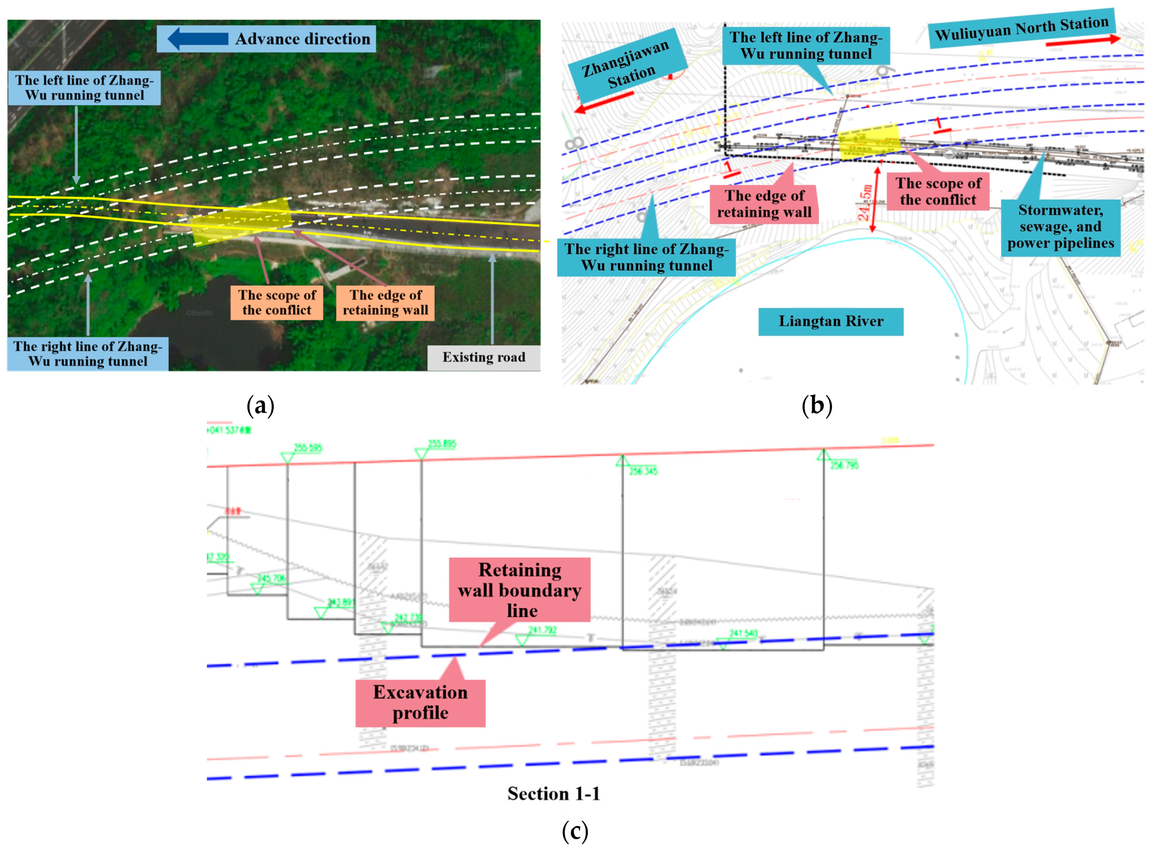
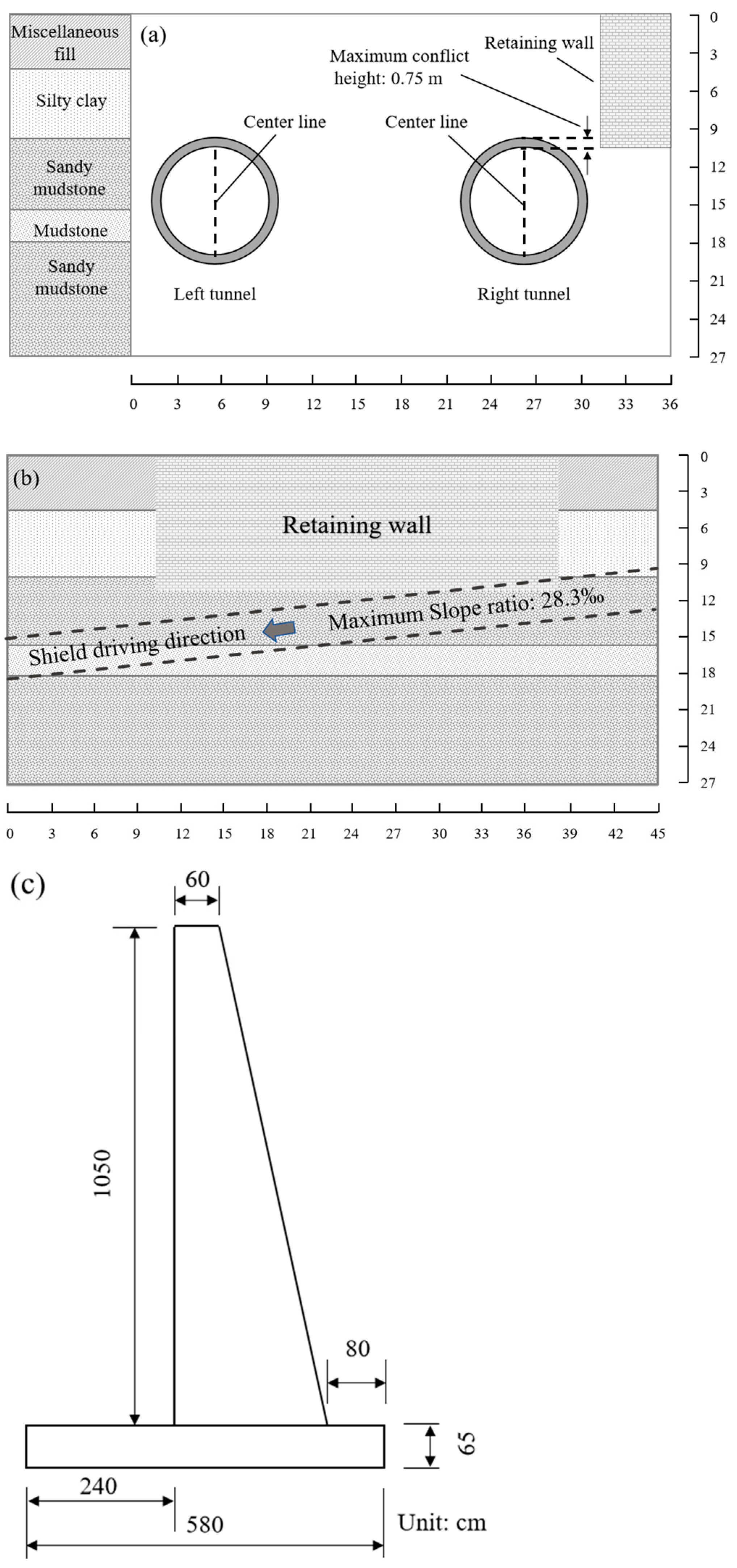
As shown in Figure 2a,b, the right tunnel passed beneath the existing highway at chainage YK33 + 849 to YK33 + 878. Within the chainage YK33 + 862 to YK33 + 878, the tunnel segment crown conflicted with the gravity retaining wall foundation, with a maximum conflict height of 0.75 m, as shown in Figure 2c. The retaining wall was constructed using C30 plain concrete, with its foundation penetrating 0.5 m into moderately weathered sandstone. The foundation’s bottom elevation within the underpass section ranged from 241.54 to 241.94 m. The maximum longitudinal slope in this section was 28.3‰. The undercrossing area for the right tunnel lay between rings 416 and 432. The right tunnel began passing beneath the existing highway retaining wall on 7 November 2024, and the underpass was completed on 10 November 2024.

2.2. Geological Condition

Figure 3 illustrates the strata conditions of the section where the shield tunnel passes beneath the existing highway. The geological conditions of the section were successively miscellaneous fill, silty clay, sandy mudstone, and mudstone. The shield tunnel primarily traversed moderately weathered sandstone and mudstone, the above parts were soft and the below parts were hard. The groundwater comprised Quaternary loose stratum pore water and bedrock fissure water, the groundwater level was 0.5–0.8 m below the surface. The parameters of sandstone and mudstone formations are shown in Table 1. The mechanical properties of sandy mudstone are different with those of sandstone significantly, which could increase the difficulty of controlling the EPB shield posture and tunneling parameters. Moreover, mudcake formation, tool wear and uneven tool abrasion are easily caused during shield construction in sandstone and mudstone strata, which could severely impact construction progress. In sandstone–mudstone alternating strata, the EPB shield tunnel faces strict control of tunneling parameters when undercrossing the existing highway at a steep slope. Cementitious mortar was used as the synchronous grouting material in this project, its specific proportions are detailed in Table 2. It featured a setting time of under 6 h, a shrinkage rate below 5%, and a consistency of 12 ± 2 cm.

2.3. Monitoring Program

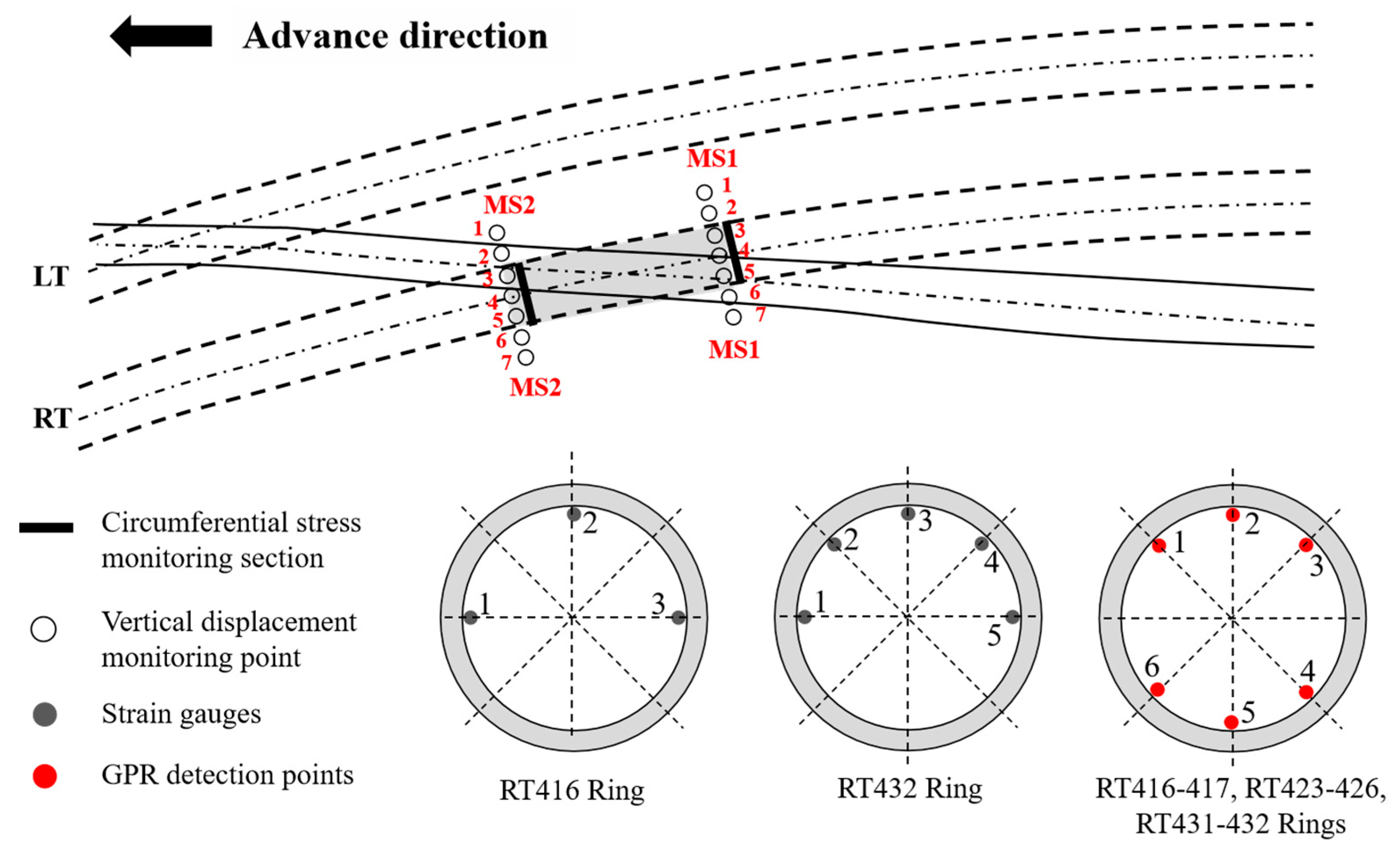
A total station system was employed to monitor highway settlement during tunnel excavation, facilitating timely optimization of shield tunneling parameters to maintain the structural safety of tunnel and highway. Simultaneously, strain gauges were installed within the new tunnel to continuously collect circumferential strain data of the tunnel lining. Two monitoring cross-sections, MS1 and MS2, were designated for real-time observation of highway settlement throughout the shield machine’s approach, passage, and departure. Each monitoring cross-section was equipped with seven monitoring points, the space distance was 3 m. Figure 4 illustrates the arrangement of monitoring points for each cross-section. “LT” and “RT” denote the newly constructed “left tunnel” and “right tunnel”, respectively. After the tunnel assembly was completed at the shield machine’s tail and the tunnel ring was formed, strain gauges were immediately installed at the designated monitoring positions. Additionally, the GSSI SIR-4000 ground penetrating radar (GPR) was employed for scanning backfill grouting quality in the section of the RT underpassing the existing highway, analyzing and evaluating whether the backfill grouting layer had voids or compaction defects.

2.4. Detecting Principle of GPR in Grouting Quality Behind Tunnel Lining

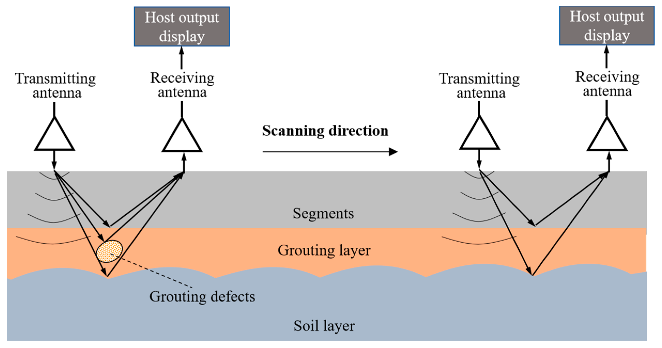
Ground Penetrating Radar (GPR) mainly consists of a control unit, a transmitting antenna, and a receiving antenna. GPR emits broadband, short-pulse electromagnetic waves through the transmitting antenna. When these waves encounter the interface between media with different electrical properties, refraction and reflection occur due to the variation in electromagnetic characteristics. The reflected waves are then received by the receiving antenna. By capturing response signals and analyzing their waveform, phase, and amplitude, the target medium distribution can be interpreted. The electromagnetic method represented by GPR is a commonly used non-destructive testing technique, particularly adept at detecting multilayered media and buried objects. In tunnel structures, backfill grouting is classified as a concealed structure. The segment lining, grouting layer, and soil layer can be simplified into a three-layer medium model for analysis. The application principle of the GPR detection method for backfill grouting in shield tunnels is shown in Figure 5. Due to the distinct electrical properties of at interfaces among the segment lining, grouting material, and soil medium, as well as defect regions, electromagnetic waves are reflected and transmitted during propagation. The reflection intensity can be calculated using the medium reflection coefficient R and transmission coefficient T in Formulas (1) and (2). The relative dielectric constant is calculated using Equation (3), and the propagation speed of electromagnetic waves in the medium is determined by Formula (4). By analyzing the characteristic information of the reflected echoes, the morphology, location, and depth of grouting interfaces and defects can be identified.
R = ε 1 ε 2 ε 1 + ε 2
T = 2 ε 2 ε 1 + ε 2
ε r = ( 0.3 t 2 d ) 2
ν = c ε r
where ɛ represents the relative dielectric constant, R represents the reflection coefficient, T is the transmission coefficient, ɛ1 represents the dielectric constant of the upper layer, ɛ2 represents the dielectric constant of the lower layer, εr is the relative dielectric permittivity, t represents the two-way travel time (ns), d is the thickness or distance to the calibration target (m), ν represents the electromagnetic wave velocity (m/ns), and c is the speed of light in free space.
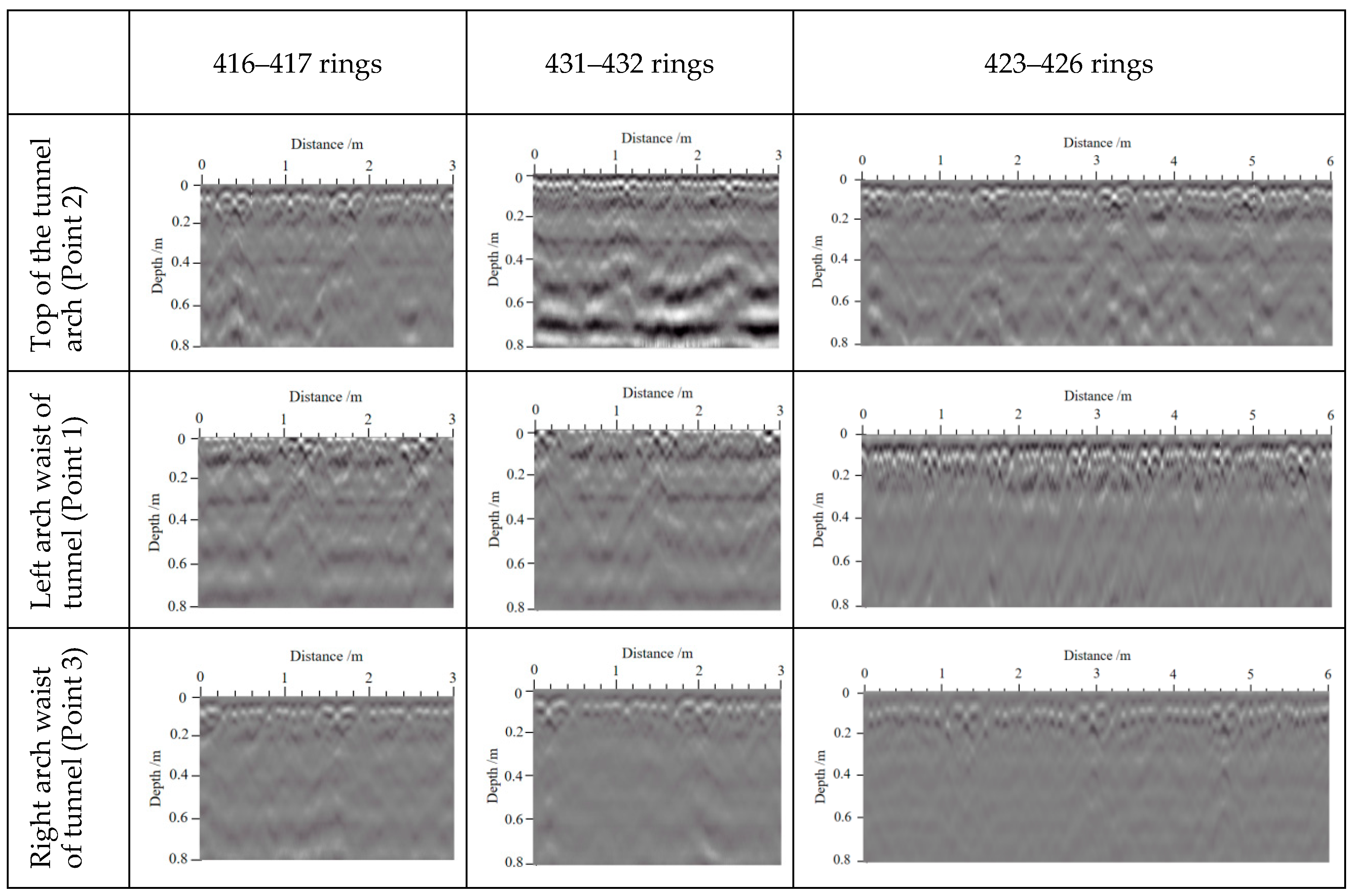
After selecting the measurement antenna, a test was conducted to determine the recording parameters. Based on on-site adjustments and analysis, the final parameters were determined as follows: (1) the detection speed was controlled at approximately 3 km/h, (2) each trace (i.e., each ground sampling point) included 512 time sampling points, (3) a 900 MHz antenna, (4) the sampling mode was continuous detection. The radar survey lines were arranged longitudinally along the tunnel, with six continuous detection lines set up at specific locations (Figure 4). The key characteristics for determining the compaction of backfill grouting behind the tunnel lining were as follows. When the detection signal amplitude was weak or there was no interface reflection signal, the backfill grouting can be considered relatively compact. When the reflection signal from the lining interface was strong, with noticeable triphasic characteristics, and there were still strong reflection signals below it with a significant time difference between the two signal groups, it indicated the existence of pores in the grout. When the grouting was not compacted, the strong reflection signals from the lining interface appeared as a diffracted arc along the phase axis, and they were discontinuous and more scattered.
To ensure the accuracy and reliability of the GPR data, a systematic post-processing workflow was applied to the acquired raw data. First, direct current (DC) drift correction was performed by subtracting the mean value of each trace to eliminate baseline offset, establishing a foundation for amplitude analysis. Subsequently, the direct wave was removed via background subtraction, wherein the average trace of the entire survey line was subtracted from each individual trace. This effectively suppressed interference from antenna coupling and surface reflections, thereby enhancing the effective signals from behind the segment lining [27]. To compensate for electromagnetic wave attenuation in the ground, automatic gain control with a time window of 30 ns was applied. This provided reasonable amplification of reflection amplitudes within the 2–3 m depth range behind the segments, facilitating the identification of grouting variations. Distance normalization was then conducted by resampling the radar traces to a 0.1 m trace interval based on the odometer information, ensuring consistent distance coordinates across different survey lines. Band-pass filtering in the frequency domain was implemented with a passband of 300–1500 MHz, centered on the antenna’s central frequency (900 MHz), to suppress low-frequency drift and high-frequency clutter, thereby improving the signal-to-noise ratio of the effective signals. Finally, a 3-trace moving average filter was applied in the spatial domain to smooth random noise and enhance the continuity of reflection events, aiding subsequent interpretation. The aforementioned processing steps significantly improved the radar image quality, providing a reliable basis for the quantitative assessment of grouting quality.

3. Field Observations

3.1. Shield Tunneling Parameters

The shield tunneling parameters are crucial for maintaining the stability of the overlying highway. During the tunnel construction process under the existing highway, tunneling parameters should be dynamically adjusted according to real-time monitoring data.
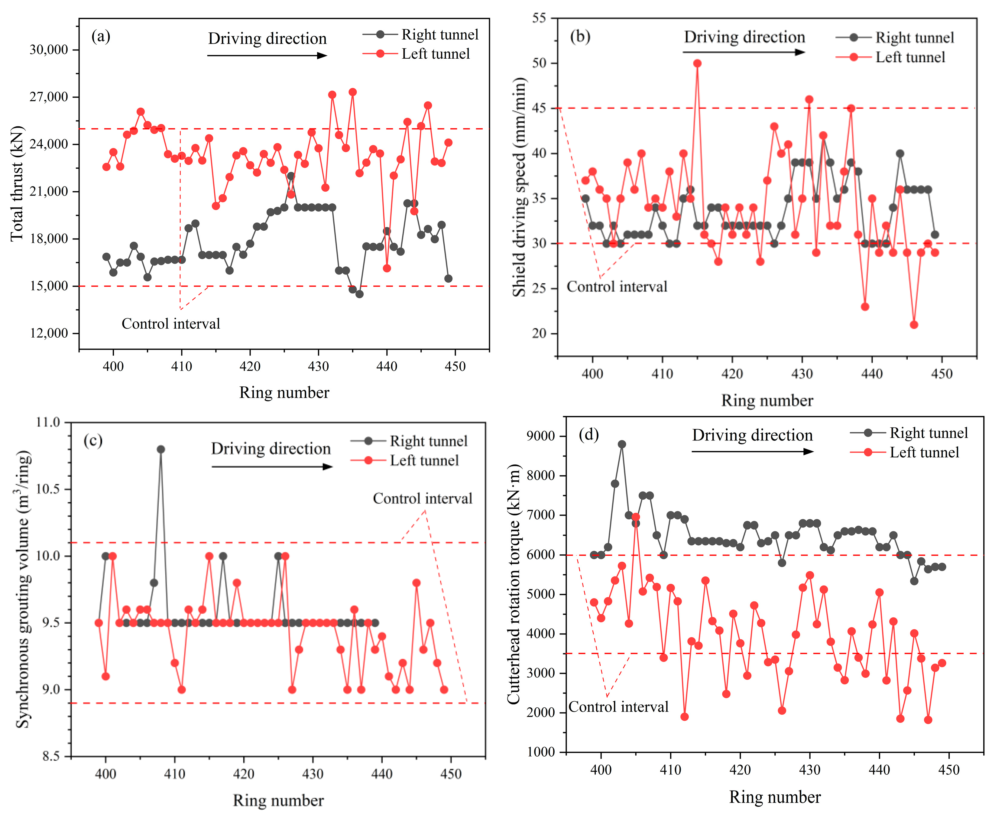
The variation trends of tunneling parameters for the LT and RT are shown in Figure 6. The shield tunneling parameters exhibited significant fluctuations across different sections, particularly during the 416 to 432 ring stage of tunneling beneath the existing highway. As illustrated in Figure 6a, when the shield approached the highway, the total thrust increased significantly to maintain stable settlement, and part of the thrust overcame the increased frictional resistance between the shield and the reinforced soil [28,29]. After advancing to the 432nd ring, the total thrust gradually decreased to approximately 15,000 kN. Figure 6b shows that the driving speed rapidly decreased from 50 to 30 mm/min at the starting point of the underpass section, and then it gradually recovered. Additionally, Figure 6c–e illustrated that the synchronous grouting volume fluctuated around approximately 9.5 m3 during the excavation process, while the cutterhead torque and rotational speed showed minimal variation, remaining essentially constant. As shown in Figure 6f, the soil pressure of the right tunnel exhibited a significant increase during the construction beneath the existing highway, followed by a gradual decrease. In contrast, the soil pressure of the left tunnel showed no significant fluctuations, remaining roughly constant at 90 kPa. The control of these construction parameters provided a comparative framework for assessing the impact of close-range EPB shield tunneling on existing structures.

3.2. Deformation of the Existing Highway

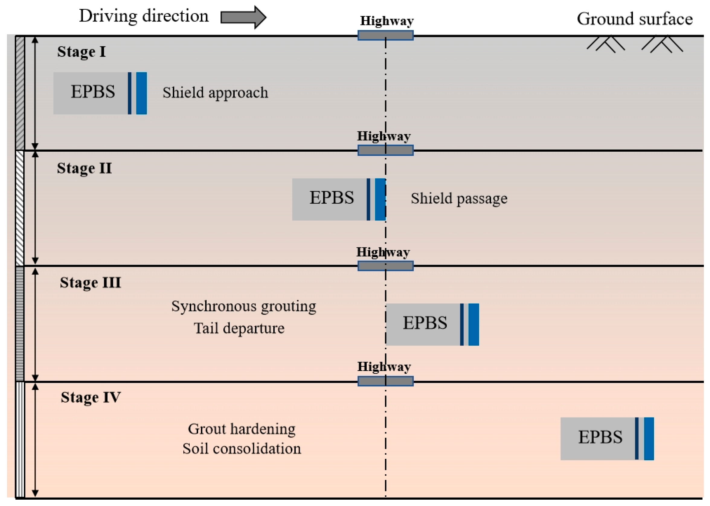
As shown in Figure 7, according to the spatial distance between the EPB shield and the existing highway, the construction process of the tunnel can be categorized into four main stages: (I) the approaching stage, (II) the crossing stage, (III) synchronous grouting and shield tail departure, and (IV) backfill grouting hardening and stabilization of the surrounding soil. Figure 8 and Figure 9 illustrate the settlement trends of the existing highway in different construction stages of RT and LT, respectively. It was noteworthy that positive settlement values indicated uplift of the existing highway, while negative values represented subsidence.
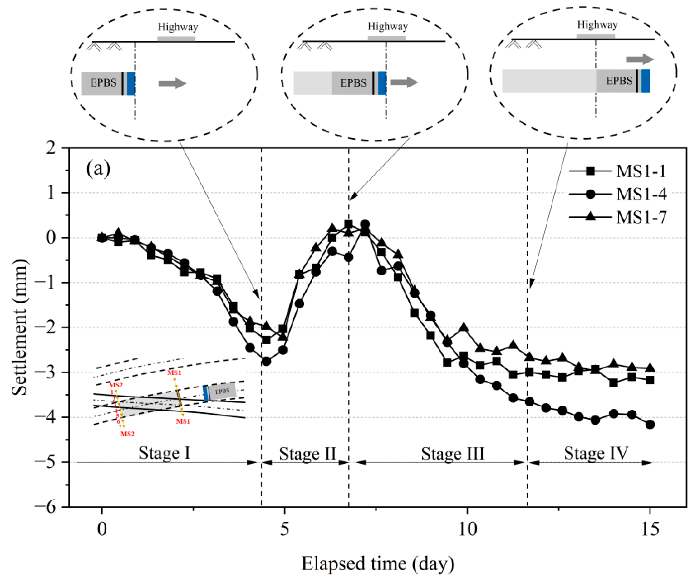
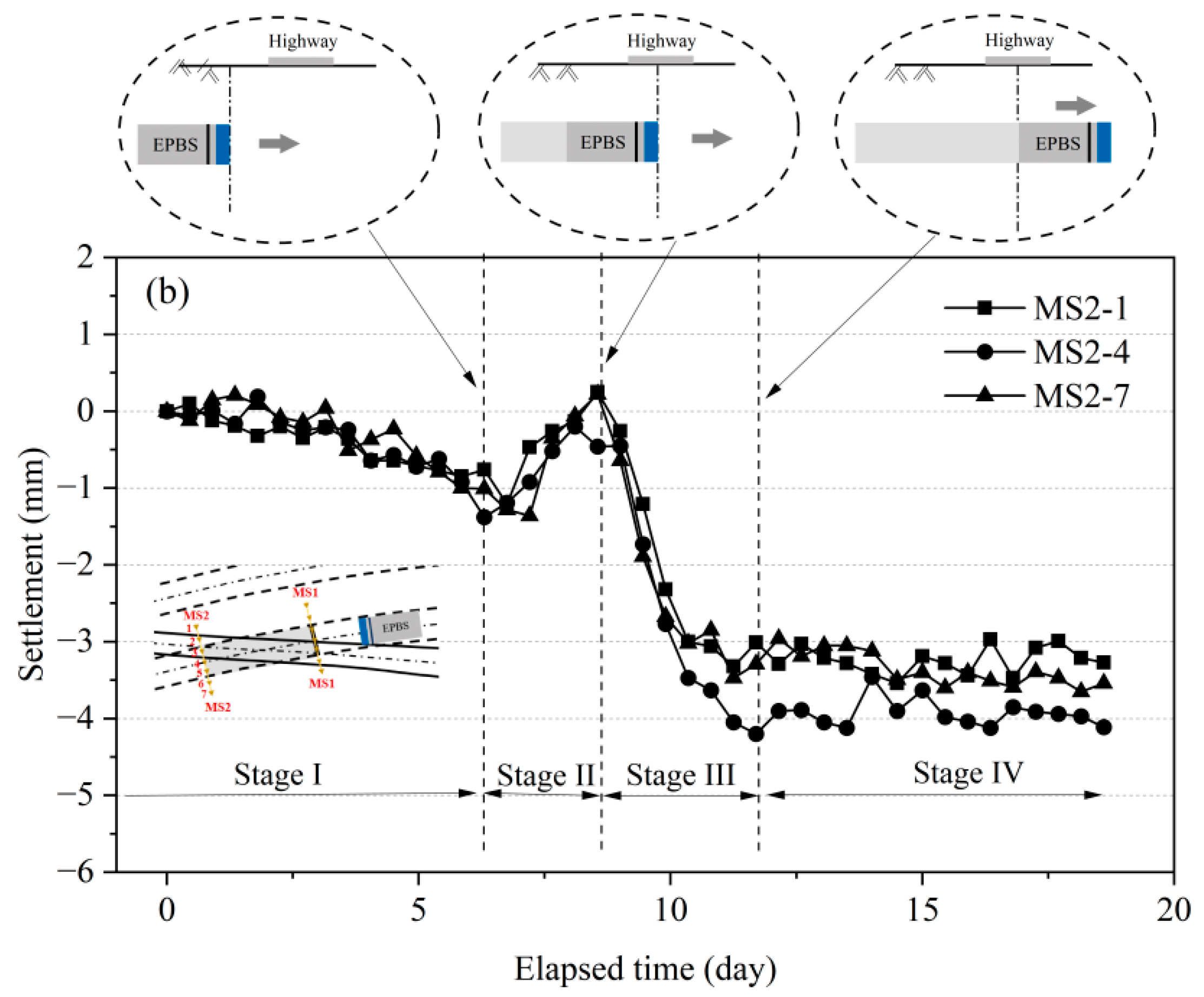
As shown in Figure 8, during RT construction, highway settlement induced by the close-proximity underpass of EPB shield in sandstone–mudstone alternating strata could be categorized into four stages: (I) initial settlement, (II) uplift, (III) secondary settlement, and (IV) stabilization. Monitoring points MS1-1, MS1-4, and MS1-7 exhibited consistent settlement evolution patterns, whereas MS2-1, MS2-4, and MS2-7 experienced similar settlement evolution stages, but they showed no significant settlement during the first stage. Notably, the initial settlement in the first stage was significantly lower than the secondary settlement in the third stage, indicating that the secondary settlement caused by shield tail detachment was significantly greater than the initial settlement induced by distant shield construction. As shown in Figure 9a, during the excavation of the left-line tunnel, monitoring points MS1-1, MS1-4, and MS1-7 of the existing highway primarily experienced three stages: slow settlement, rapid settlement, and stabilization. The settlement impact of the LT construction on monitoring points MS2-1, MS2-4, and MS2-7 mainly exhibited three stages: slight uplift, rapid settlement, and eventual stabilization (Figure 9b). As the LT passed laterally under the existing highway, its impact on the final settlement of the highway was significantly smaller than that of the RT, with the final settlement controlled to approximately 1 mm.
Based on monitoring results, the existing highway settlement caused by the RT excavation can be summarized into four stages, with specific settlement trends as follows. Stage I: During this stage, the settlement ranged from approximately 0.8 to 3 mm, primarily caused by groundwater drawdown due to shield construction (groundwater level: 0.5–0.8 m below the surface). The new tunnel was located in a sandy mudstone layer, close to an existing river (the retaining wall edge is 24.5 m away from the river), and the layer has strong permeability (Figure 2). Stage II: The existing highway underwent an uplift of about 0.5 mm at this stage, which could be caused by two factors: (1) replenishment of groundwater loss following shield advancement, and (2) increased chamber pressure (Figure 6f). Stage III: As the shield underpassed the existing highway area, the settlement increased significantly, ranging from 0.8 to 4.2 mm. This was primarily induced by friction between the shield and the surrounding soil, as well as volume loss at the shield tail. Stage IV: Gradual hardening of the grouting materials and consolidation of the surrounding soil led to slow settlement of the highway [30]. During the grouting hardening process, water discharge likely caused grouting volume shrinkage, and dissipation of pore water pressure caused by shield construction disturbances further contributed to long-term settlement of the existing highway. The final settlement stabilized at values between 0.9 and 4.2 mm.

3.3. Settlement Trough of the Existing Highway

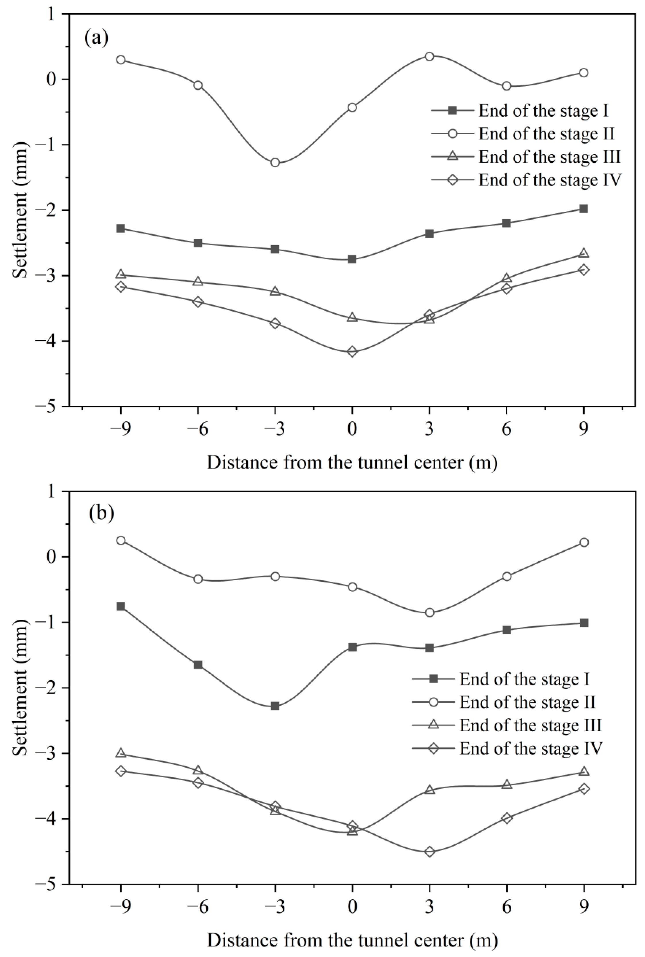
Figure 10 shows the measured settlement troughs during the four construction stages as the RT tunnel passes beneath the existing highway. The conflict area between the new tunnel and the retaining wall of the existing highway was located directly above the RT, and the monitoring points were concentrated in the intersection region. This study primarily focused on analyzing the evolution characteristics of settlement troughs caused by RT construction. It should be noted that the observed settlement troughs represent localized rather than complete patterns due to the distribution of monitoring points.
As shown in Figure 10a, before the shield cutterhead was close to monitoring section MS1, uneven settlement had already occurred on the existing highway. The settlement profile exhibited a slightly “V” shape, with the maximum settlement at the RT centerline. However, when the tunnel face reached MS1, the settlement trough transformed into a slightly “W”-shaped profile. The maximum settlement point shifted from the RT centerline to MS1-3 on one side of the centerline, which might be attributed to the flexible nature of the existing roadbed. By the end of the third stage, the maximum settlement point further shifted approximately 3 m to one side of the RT centerline (at MS1-5). Notably, after the tunnel face moved away from monitoring section MS1, a more pronounced settlement trough was observed, with the maximum settlement point returning to the area above the tunnel centerline. Overall, the maximum settlement points at different stages were all located within 3 m of the RT centerline. Similar phenomena were also observed at monitoring section MS2 (Figure 10b). After approximately 12 d, the settlement gradually stabilized, with the final settlement values at sections MS1 and MS2 controlled within ranges of 2.9–4.2 and 3.2–4.5 mm, respectively. The results demonstrated that the reasonable tunneling parameters applied in this project effectively minimized the disturbance of tunnel construction on the existing structures.

3.4. Circumferential Stresses of the New Tunnels

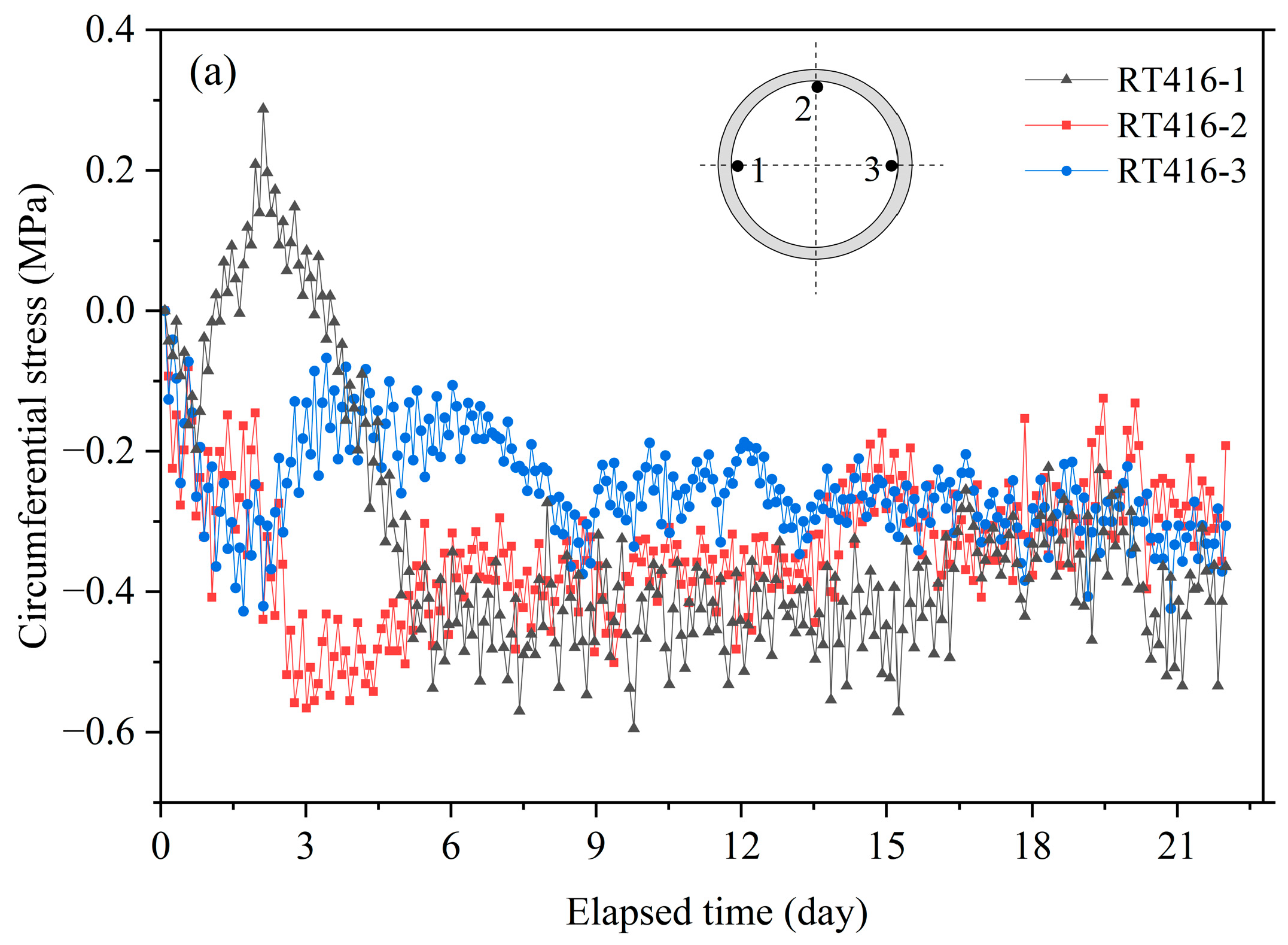
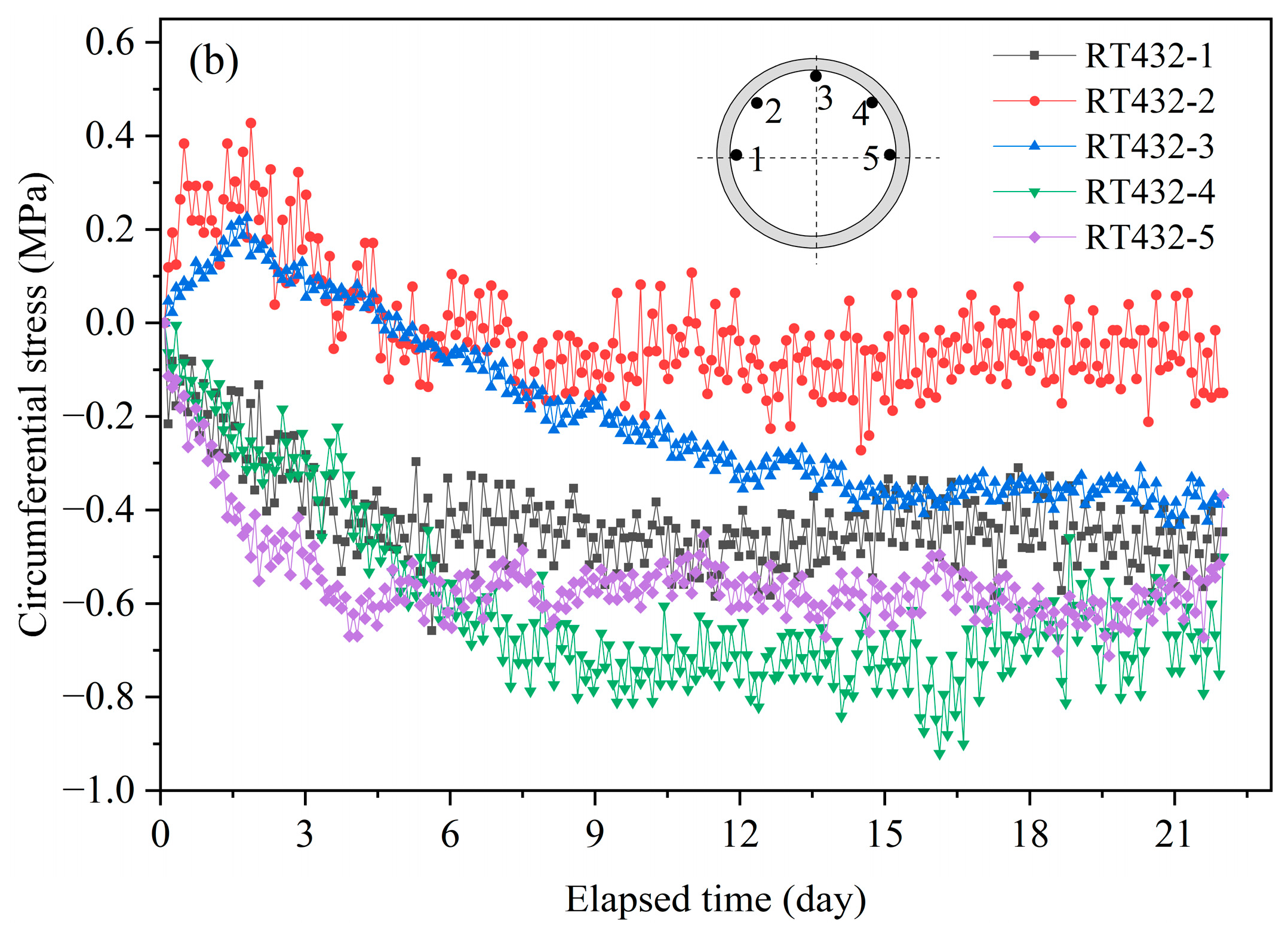
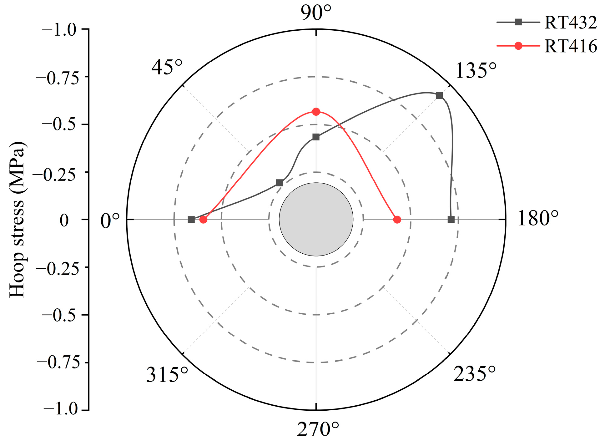
Based on Hooke’s law, the circumferential stress of the tunnel can be calculated by monitoring the strain. The circumferential stress equaled to the product of the elastic modulus of the segment lining and the strain. After the segment lining was assembled, the circumferential stress of the newly constructed tunnel was monitored in real time. The variation in circumferential stress over time for Rings 416 and 432 in the RT is shown in Figure 11. Positive values represented tensile stresses on the segment lining, while negative values represented compressive stresses. Under the influence of soil pressure around the tunnel, the circumferential stress at each monitoring surface increased rapidly over time. During the early stage of shield tail departure from the monitoring surface, the circumferential stress on the segment lining was mainly compressive, but tensile stress was observed at monitoring points RT416-1, RT432-2, and RT432-3. Over time, the tensile stress at monitoring points RT416-1 and RT432-3 gradually decreased and eventually transformed into compressive stress. After the shield tunnel passed beneath the existing highway, the circumferential stress at all monitoring points gradually stabilized. The maximum circumferential stress observed at all monitoring points is shown in Figure 12. It can be seen that the maximum circumferential stresses at the two monitoring surfaces occurred at RT416-3 and RT432-4, the values were −0.595 and −0.921 MPa, respectively, which were far below the design strength values.

3.5. Evaluation of Backfill Grouting Quality Based on GPR Technology

GPR has been proved to be an effective and efficient non-destructive testing tool, capable of accurately identifying localized defects such as insufficient grouting and voids in tunnels within water-rich strata [31,32]. This finding underscored the significant application value of GPR for quality control and engineering risk early-warning in complex geotechnical environments. However, the limitations of this method must be explicitly acknowledged. The technique is significantly affected by the reinforcement mesh within the tunnel segments and the high electrical conductivity of water-rich strata [33]. The reinforcement mesh creates a strong shielding effect on electromagnetic waves, while the high conductivity of groundwater causes rapid attenuation of wave energy. These two factors collectively severely limit the penetration depth of the radar waves and the resolution of deeper details, posing challenges for the precise assessment of grouting conditions at greater distances behind the segments. Therefore, this study integrated GPR surveys with limited borehole coring for validation, creating a complementary approach that combined the benefits of “non-destructive comprehensive scanning” and “targeted destructive verification.” This integrated rapid and comprehensive coverage of GPR while utilizing boreholes to visually confirm critical defects and overcome depth limitations, thereby collectively providing a more scientific and reliable evaluation basis for grouting construction quality.
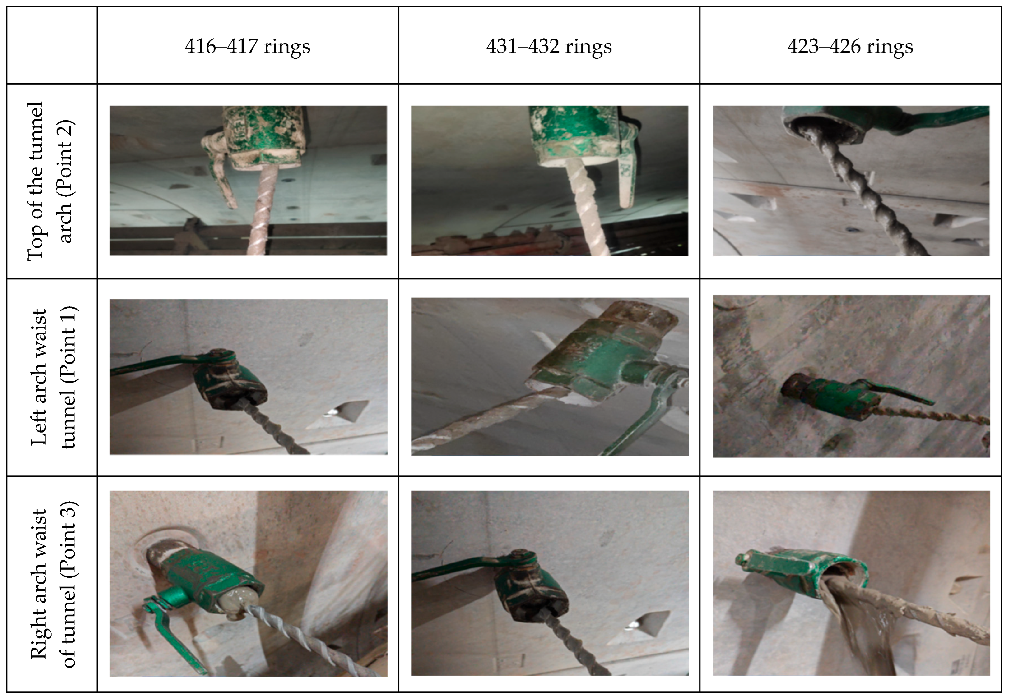
The backfill grouting quality of the RT crossing under the existing highway section was assessed using GPR technology. Figure 13 presents the GPR measurement data for typical survey lines of Rings 416–417, 431–432, and 423–426 (including the tunnel crown, left arch waist, and right arch waist). The specific layout of the survey lines is shown in Figure 4. In Figure 13, the tunnel crown (Point 2) of Rings 416–417 and 423–426 exhibited weak signal amplitudes, with almost no interface reflection signals. No significant voids or loose defects were detected, indicating that the backfill grouting in this area was compact. However, the radar reflection wave at the tunnel crown of Ring 431–432 showed strong low-frequency reflections with partially discontinuous in-phase axes and disordered lower reflection signals, suggesting that the grouting layer at this location was inadequately filled. As shown in Figure 14, borehole verification revealed insufficient filling of grout materials at this location, with some seepage observed in the slurry. Considering the proximity to a river and the abundant groundwater, it was speculated that the grouting materials were diluted and dispersed by the groundwater. As shown in Figure 13, the GPR images for other survey lines within the detection depth range showed uniform and stable reflection signals, with no significant voids or cracks observed. The grouting layer’s depth distribution was uniform, indicating good grouting quality. Subsequent core drilling verification confirmed that all detected points were adequately filled with grout, as shown in Figure 14.

4. Conclusions

Taking an EPB shield closely crossing an existing highway in a sandstone–mudstone alternating stratum as an example, this study investigated the vertical surface displacement, settlement trough evolution, and tunnel stress changes caused by shield construction. The quality of synchronous grouting at the shield tail was evaluated using GPR technology and borehole verification. The findings provided practical insights for similar projects. The following conclusions were obtained.
(1)
Highway Settlement induced by the close-proximity undercrossing of the EPB shield can be divided into four phases: (I) initial settlement, primarily due to groundwater level drawdown caused by tunneling activities, (II) uplift, resulting from groundwater recharge and increased chamber pressure, (III) secondary settlement, induced by soil friction and tail void volume loss as the shield passed through the region, and (IV) stabilization stage, it was characterized by gradual settlement caused by grout hardening and soil consolidation. Notably, the secondary settlement caused by shield tail detachment was significantly greater than the initial settlement induced by distant shield construction.
(2)
The settlement trough of the existing highway exhibited distinct characteristics during the four stages of tunnel undercrossing. The maximum settlement point did not always lie on the tunnel centerline, but shifted towards one side, remaining within 3 m of the centerline. Approximately 12 d later, the settlement of the existing highway gradually stabilized, with the final settlement at the monitored sections controlled between 2.9 and 4.5 mm.
(3)
During the early stages of shield tail detachment, the circumferential stress of the tunnel changed rapidly. The circumferential stress was primarily compressive, with tensile stress observed at some monitoring points. Over time, the tensile stress at the monitoring points gradually transitioned to compressive stress. After the tunnel undercrossing, the circumferential stress gradually stabilized. The maximum circumferential stresses occurred at the tunnel crown and haunch, measuring −0.595 and −0.921 MPa, respectively.
(4)
GPR and borehole results indicated that in groundwater-rich strata, areas with poor grouting quality tended to occur at the tunnel crown, characterized by low-frequency strong reflections, discontinuities in signal phase axes, and chaotic lower reflection signals. Groundwater diluted and dispersed the grouting material, resulting in insufficient density of the grouting layer at the tunnel crown. In contrast, grouting quality was generally good along other survey lines and within the detection depth range.

Author Contributions

C.M.: Writing—original draft preparation, Writing—review and editing, Methodology, Formal Analysis. Q.W.: Writing—original draft preparation, Data curation, Methodology. J.W.: Methodology, Conceptualization, Resources. F.S.: Funding acquisition, Supervision, Writing—review and editing. H.Y.: Methodology, Investigation, Writing—review and editing. F.L.: Methodology, Investigation, Writing—review and editing. All authors have read and agreed to the published version of the manuscript.

Funding

This study was financially supported by National Natural Science Foundation of China (Grant No. 51909140), Shandong Provincial Youth Innovation Science and Technology Support Program (2021KJ034), Opening Project of Tunnel and Underground Engineering Research Center of Jiangsu Province (2023-SDJJ-04), Young Talent Program of Ocean University of China (No. 862101013168), and Key Technologies for Rapid Shield Tunneling in Long-Distance and Large-Slope Sand-Mudstone Interbedded Strata (20240137).

Institutional Review Board Statement

Not applicable.

Informed Consent Statement

Not applicable.

Data Availability Statement

The original contributions presented in this study are included in the article. Further inquiries can be directed to the corresponding author.

Conflicts of Interest

Authors Chaojun Mao and Jinlong Wang were employed by the company China First Highway Engineering Co., Ltd.; and the author Hui Yao was employed by the company Chongqing Railway Group Co., Ltd. The remaining authors declare that the research was conducted in the absence of any commercial or financial relationships that could be construed as a potential conflict of interest.

References

  1. Fang, Q.; Zhang, D.; Wong, L.N.Y. Shallow tunnelling method (STM) for subway station construction in soft ground. Tunn. Undergr. Space Technol. 2012, 29, 10–30. [Google Scholar] [CrossRef]
  2. Fang, Q.; Liu, X.; Zhang, D.; Lou, H. Shallow tunnel construction with irregular surface topography using cross diaphragm method. Tunn. Undergr. Space Technol. 2017, 68, 11–21. [Google Scholar] [CrossRef]
  3. Yu, L.; Zhang, D.; Fang, Q.; Cao, L.; Xu, T.; Li, Q. Surface settlement of subway station construction using pile-beam-arch approach. Tunn. Undergr. Space Technol. 2019, 90, 340–356. [Google Scholar] [CrossRef]
  4. Yang, H.; Shi, H.; Jiang, X.; Liu, C.; Yu, L. Study on influence of construction process of double-line shield tunnels on frame structure. Geotech. Geol. Eng. 2021, 39, 1465–1484. [Google Scholar] [CrossRef]
  5. Zheng, G.; Fan, Q.; Zhang, T.; Zheng, W.; Sun, J.; Zhou, H.; Diao, Y. Multistage regulation strategy as a tool to control the vertical displacement of railway tracks placed over the building site of two overlapped shield tunnels. Tunn. Undergr. Space Technol. 2019, 83, 282–290. [Google Scholar] [CrossRef]
  6. Di, H.; He, P.; Li, X.; Xiao, F.; Chen, H. Influence of large-diameter shield tunneling on deformation of adjacent high-speed railway subgrade in soft soils and effectiveness of protective measures. Tunn. Undergr. Space Technol. 2025, 156, 106260. [Google Scholar] [CrossRef]
  7. Lin, X.; Chen, R.; Wu, H.; Cheng, H. Deformation behaviors of existing tunnels caused by shield tunneling undercrossing with oblique angle. Tunn. Undergr. Space Technol. 2019, 89, 78–90. [Google Scholar] [CrossRef]
  8. Lai, H.; Zheng, H.; Chen, R.; Kang, Z.; Liu, Y. Settlement behaviors of existing tunnel caused by obliquely under-crossing shield tunneling in close proximity with small intersection angle. Tunn. Undergr. Space Technol. 2020, 97, 103258. [Google Scholar] [CrossRef]
  9. Li, Z.; Chen, Z.; Yang, Y.; Jiang, Y.; Xu, X.; Hu, Q. Deformation characteristics of existing tunnels induced by above-crossing quasi-rectangular shield tunnel. Transp. Geotech. 2024, 45, 101227. [Google Scholar] [CrossRef]
  10. Ma, S.; Shao, Y.; Liu, Y.; Jiang, J.; Fan, X. Responses of pipeline to side-by-side twin tunnelling at different depths: 3D centrifuge tests and numerical modelling. Tunn. Undergr. Space Technol. 2017, 66, 157–173. [Google Scholar] [CrossRef]
  11. Liu, X.; Zhang, R.; Jiang, A.; Fang, Q.; Ma, X. Mechanical behaviors and soil gap formation of existing pipeline based on large-deformation theory. Int. J. Geomech. 2023, 23, 04023098. [Google Scholar] [CrossRef]
  12. Zhao, Q.; Li, K.; Cao, P.; Liu, Y.; Pang, Y.; Liu, J. A study on the influence of double tunnel excavations on the settlement deformation of flood control dikes. Sustainability 2023, 15, 12461. [Google Scholar] [CrossRef]
  13. Lin, Q.; Cao, P.; Dong, T.; Liu, J.; Zhao, Q.; Zhu, W. Numerical Simulation of Flood Control Levee Deformation by Shield Tunnel Excavation through the Liuyang River: A Case Study. Geofluids 2023, 2023, 8925891. [Google Scholar] [CrossRef]
  14. Xu, Q.; Zhu, H.; Ma, X.; Ma, Z.; Li, X.; Tang, Z.; Zhuo, K. A case history of shield tunnel crossing through group pile foundation of a road bridge with pile underpinning technologies in Shanghai. Tunn. Undergr. Space Technol. 2015, 45, 20–33. [Google Scholar] [CrossRef]
  15. Simic-Silva, P.T.; Martínez-Bacas, B.; Galindo-Aires, R.; Simic, D. 3D simulation for tunnelling effects on existing piles. Comput. Geotech. 2020, 124, 103625. [Google Scholar] [CrossRef]
  16. Liu, W.; Wang, M.; Luo, G.; Lu, W.; Xiao, H. Horizontal response of existing pile induced by adjacent shield tunnelling with large longitudinal slope. Tunn. Undergr. Space Technol. 2024, 153, 106036. [Google Scholar] [CrossRef]
  17. Gokuldas, S.; Banerjee, S.; Nimbalkar, S.S. Effects of tunneling-induced ground movements on stability of piled raft foundation: Three-dimensional finite-element approach. Int. J. Geomech. 2020, 20, 04020104. [Google Scholar] [CrossRef]
  18. Zhou, L.; Zhu, Y. Analysis of stratum settlement laws caused by the construction of shallow-buried expressway tunnels with large span and small spacing. Geotech. Geol. Eng. 2021, 39, 1485–1495. [Google Scholar] [CrossRef]
  19. Qian, W.; Qi, T.; Zhao, Y.; Le, Y.; Yi, H. Deformation characteristics and safety assessment of a high-speed railway induced by undercutting metro tunnel excavation. J. Rock Mech. Geotech. Eng. 2019, 11, 88–98. [Google Scholar] [CrossRef]
  20. Wang, G.; Shan, Y.; Detmann, B.; Lin, W. Physics-Informed Neural Network (PINN) model for predicting subgrade settlement induced by shield tunnelling beneath an existing railway subgrade. Transp. Geotech. 2024, 49, 101409. [Google Scholar] [CrossRef]
  21. Song, M.; Liu, J.; Wang, X.; Lou, H.; Lin, X. Study on railway subgrade settlement induced by an ultra-large-diameter shield tunnel crossing under railway subgrade. Symmetry 2022, 15, 75. [Google Scholar] [CrossRef]
  22. Zhang, Q.; Xia, T.; Ding, Z.; Huang, X.; Lin, C. Effect of nearby undercrossing tunneling on the deformation of existing metro tunnel and construction control. Rock Soil Mech. 2016, 37, 3561–3568. [Google Scholar]
  23. Zheng, Y.; Wu, K.; Sun, J.; Chen, R.; Li, Y.; Yang, S. Study on the influence of close distance construction of urban tunnel on the existing station. Geotech. Geol. Eng. 2021, 39, 4765–4780. [Google Scholar] [CrossRef]
  24. Li, P.; Dai, Z.; Huang, D.; Cai, W.; Fang, T. Impact analysis for safety prevention and control of special-shaped shield construction closely crossing multiple operational metro tunnels in shallow overburden. Geotech. Geol. Eng. 2022, 40, 2127–2144. [Google Scholar] [CrossRef]
  25. Peng, F.; Ma, S. Analysis of experimental data on the effect of double-line parallel shield tunneling on the deformation of adjacent buildings. Alex. Eng. J. 2021, 60, 3957–3963. [Google Scholar] [CrossRef]
  26. Li, X.; Yuan, D. Response of a double-decked metro tunnel to shield driving of twin closely under-crossing tunnels. Tunn. Undergr. Space Technol. 2012, 28, 18–30. [Google Scholar] [CrossRef]
  27. Liu, H.; Yue, Y.; Lai, S.; Meng, X.; Du, Y.; Cui, J.; Spencer, B.F. Evaluation of the antenna parameters for inspection of hidden defects behind a reinforced shield tunnel using GPR. Tunn. Undergr. Space Technol. 2023, 140, 105265. [Google Scholar] [CrossRef]
  28. Li, T.; Liu, B.; Han, Y.; Fu, C.; Sun, Y. Structural analysis of shield machine cutting monopile using py curve based finite element method. Comput. Geotech. 2023, 161, 105605. [Google Scholar] [CrossRef]
  29. Standing, J.R.; Selemetas, D. Greenfield ground response to EPBM tunnelling in London Clay. Géotechnique 2013, 63, 989–1007. [Google Scholar] [CrossRef]
  30. Komiya, K.; Soga, K.; Akagi, H.; Jafari, M.R.; Bolton, M.D. Soil consolidation associated with grouting during shield tunnelling in soft clayey ground. Geotechnique 2001, 51, 835–846. [Google Scholar] [CrossRef]
  31. Kravitz, B.; Mooney, M.; Karlovsek, J.; Danielson, I.; Hedayat, A. Void detection in two-component annulus grout behind a pre-cast segmental tunnel liner using Ground Penetrating Radar. Tunn. Undergr. Space Technol. 2019, 83, 381–392. [Google Scholar] [CrossRef]
  32. Zeng, L.; Zhang, X.; Xie, X.; Zhou, B.; Xu, C.; Lambot, S. Measuring annular thickness of backfill grouting behind shield tunnel lining based on GPR monitoring and data mining. Autom. Constr. 2023, 150, 104811. [Google Scholar] [CrossRef]
  33. Zeng, H.; Wang, J.; Wang, J.; Du, Y.; Li, F. Evaluation of steel mesh impact on GPR detection of voids behind lining in railway tunnels. Constr. Build. Mater. 2025, 466, 140316. [Google Scholar] [CrossRef]
Figure 1. Geological situation of Zhang-Wu Interval of Chongqing Metro Line 15 Phase II Project.
Applsci 15 10884 g001
Figure 2. (a,b) Schematic diagrams showing the location of the existing highway and the new section tunnel, (c) Cross-sectional profile of Section 1-1.
Applsci 15 10884 g002
Figure 3. Geological conditions of the new tunnel underneath the existing highway section: (a) transverse geological profile, (b) longitudinal geological profile, (c) cross-section of the retaining wall.
Applsci 15 10884 g003
Figure 4. Layout diagram of monitoring sections for the existing highway.
Applsci 15 10884 g004
Figure 5. Illustration of GPR detection principle for backfill grouting quality in shield tunnels.
Applsci 15 10884 g005
Figure 6. Tunneling parameters during shield tunnel construction: (a) total thrust, (b) shield driving speed, (c) synchronous grouting volume, (d) cutterhead rotation torque, (e) cutterhead rotation speed, (f) earth chamber pressure.
Applsci 15 10884 g006aApplsci 15 10884 g006b
Figure 7. Typical stages of surface deformation caused by shield construction.
Applsci 15 10884 g007
Figure 8. Highway settlement induced by RT at different construction stages: (a) MS1, (b) MS2.
Applsci 15 10884 g008aApplsci 15 10884 g008b
Figure 9. Highway settlement induced by LT at different construction stages: (a) MS1, (b) MS2.
Applsci 15 10884 g009
Figure 10. Settlement trough evolution of the existing highway at different undercrossing stages of the RT: (a) MS1, (b) MS2.
Applsci 15 10884 g010
Figure 11. Circumferential stress variations at the monitoring sections of the newly constructed tunnel: (a) RT416, (b) RT432.
Applsci 15 10884 g011aApplsci 15 10884 g011b
Figure 12. Maximum circumferential stress on the monitoring surface of the newly constructed tunnel.
Applsci 15 10884 g012
Figure 13. GPR test results of backfill grouting in tunnel under existing highway.
Applsci 15 10884 g013
Figure 14. Images of hole opening at backfill grouting monitoring points.
Applsci 15 10884 g014
Table 1. Formation physical and mechanical parameters.
Geotechnical ParameterSandstoneMudstone
Unit weight (kN/m3)24–25.623–24.9
Cohesion (kPa)50–53870–2101
Angle of internal friction ψ (°)28–3230–40
Compressive strength (MPa)saturated value4.727.5
natural value8.237
Tensile strength (kPa)110500
Modulus of deformation (MPa)9443971
Modulus of elasticity (MPa)12354753
Poisson’s ratio µ0.380.12
Standardized value of ultimate bond strength between geotechnical body and anchors (kPa)0.41.2
Substrate friction coefficient0.500.65
Static side pressure coefficient0.4–0.550.3–0.5
Note: The modulus of deformation refers to the resistance capacity of soil and rock in all types of deformation, including both elastic and plastic deformation. The modulus of elasticity refers to the resistance capacity of the soil and rock during the fully elastic stage of deformation.
Table 2. Composition of synchronous grouting materials (kg/m3).
Cement (kg)Fly Ash (kg)Bentonite (kg)Sand (kg)Water (kg)
8030050900237
Disclaimer/Publisher’s Note: The statements, opinions and data contained in all publications are solely those of the individual author(s) and contributor(s) and not of MDPI and/or the editor(s). MDPI and/or the editor(s) disclaim responsibility for any injury to people or property resulting from any ideas, methods, instructions or products referred to in the content.