
Stability Analysis and Instability Time Prediction of Tunnel Roofs in a Karst Region Based on Catastrophe Theory

Abstract
1. Introduction
2. Tunnel Roof Rock System Model
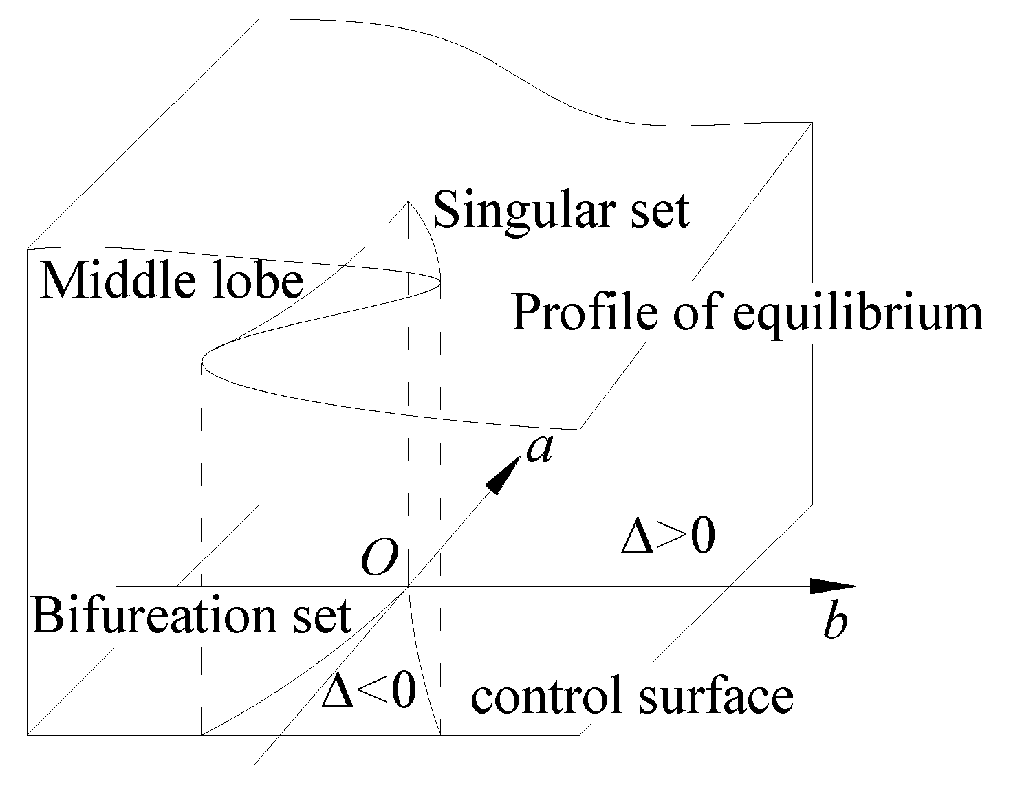
2.1. Basic Theories of Cusp Catastrophe Model
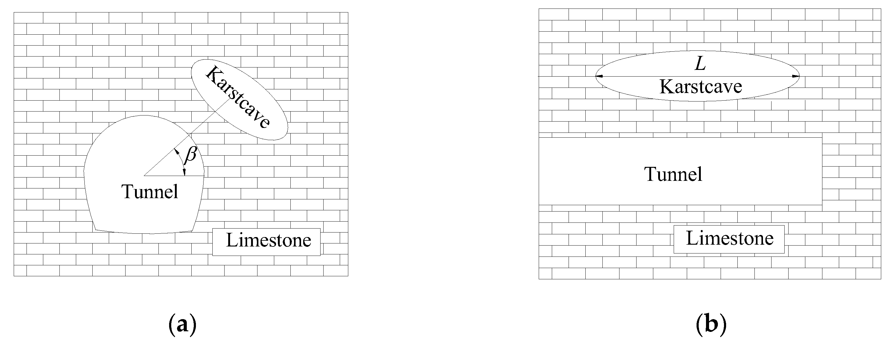
2.2. Mechanical Model and Reasonable Hypothesis
- (1)
- The rock mass system structure of the tunnel roof remains intact without cracks or defects, and the tunnel is parallel to the cave.
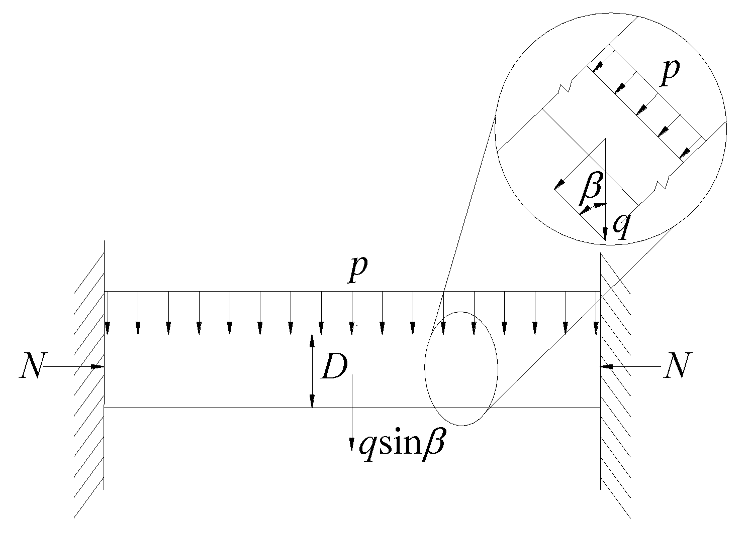
- (2)
- The mechanical model of the tunnel roof is regarded as a homogeneous beam with fixed support at both ends, and the geological tectonic stress at both ends of the rock beam is simplified as axial force.
- (3)
- The effect of water on the roof strata of the tunnel is only performed by pressure, and its weakening effect on surrounding rock parameters is ignored.
3. Analysis of Safety Thickness
3.1. Potential Function of Rock Systems
3.2. Critical Safety Thickness
4. Factor Analysis for Safety Thickness
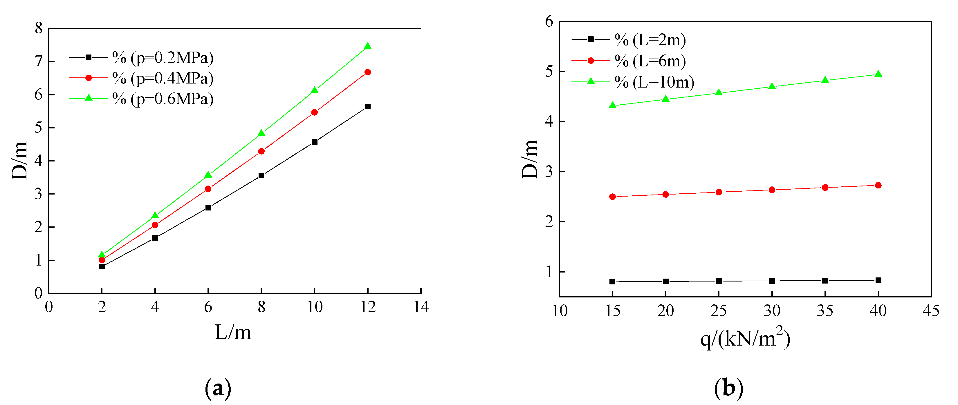
4.1. Span Influence
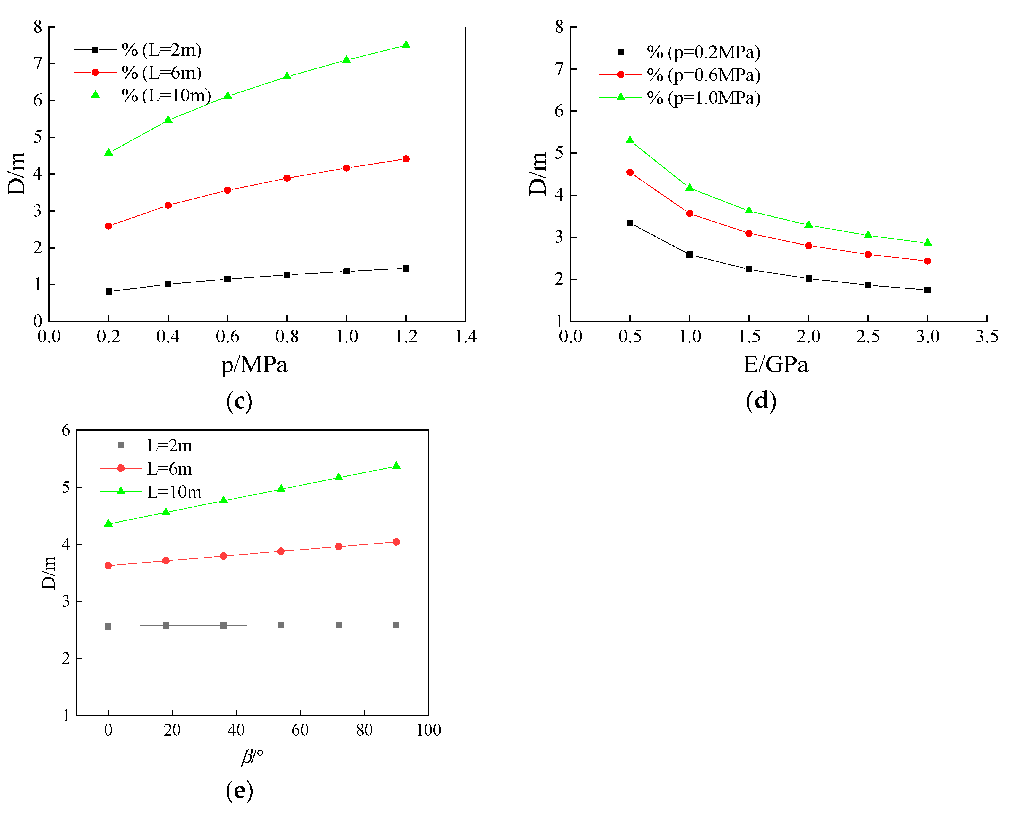
4.2. Load Influence
4.3. Modulus of Elasticity Influence
4.4. Rock Gravity Influence
4.5. Distribution Perspective of Cave Influence
5. Analysis of Engineering Example
- (1)
- DouMo Tunnel
- (2)
- LuZhuBa Tunnel
6. Instability Predicting and Verification
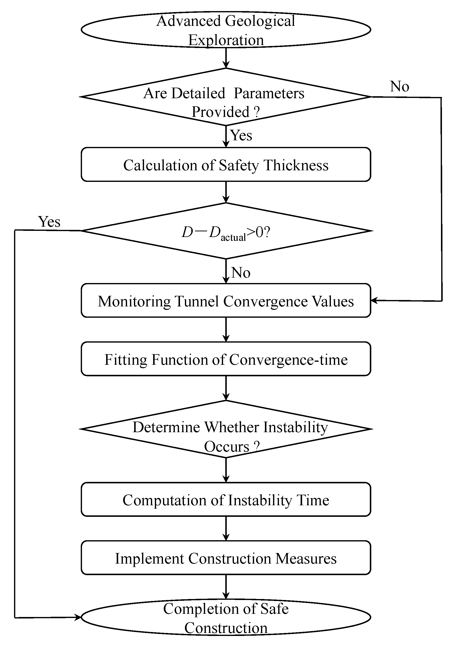
6.1. Instability Predicting Model
6.2. Practical Engineering Application
7. Conclusions
- (1)
- Through the integration of catastrophe theory and a comprehensive consideration of gravity and cave distribution factors, a discriminant equation for the rock stability of a karst tunnel vault is formulated. The proposed method for calculating roof safety thickness achieves an accuracy improvement of nearly 40% in Case 2. Comparative analyses with existing methods demonstrate that this approach exhibits enhanced accuracy and adaptability, validating its effectiveness for applications in karst tunnel engineering.
- (2)
- Factors such as cave span, the elastic model of surrounding rock, cavity pressure, and cave’s distribution significantly impact the safety thickness of the tunnel roof. Specifically, the safe thickness for a 12-m span cave increases by at least 400% compared to a 2-m span. Additionally, for large karst caves (L ≥ 10 m), the required safe thickness at the top is at least 23% greater than that at the sides. These findings emphasize the critical importance of considering the size and location of karst caves to ensure the safety of tunnel construction in karst regions.
- (3)
- A predictive model for the instability time of the karst tunnel vault is established based on empirical data. A case study illustrates a high level of agreement between calculated and observed results, as the error margin is 4%, validating the practicality of the proposed prediction approach.
Author Contributions
Funding
Institutional Review Board Statement
Informed Consent Statement
Data Availability Statement
Conflicts of Interest
References
- Gysel, M. Anhydrite dissolution phenomena: Three case histories of anhydrite karst caused by water tunnel operation. Rock Mech. Rock Eng. 2002, 35, 1–21. [Google Scholar] [CrossRef]
- Zheng, Y.C.; He, S.Y.; Yu, Y.; Zheng, J.Y.; Zhu, Y.; Liu, T. Characteristics, challenges and countermeasures of giant karst cave: A case study of Yujingshan tunnel in high-speed railway. Tunn. Undergr. Space Technol. 2021, 114, 103988. [Google Scholar] [CrossRef]
- Wang, X.L.; Lai, J.X.; He, S.Y.; Garnes, R.S.; Zhang, Y.W. Karst geology and mitigation measures for hazards during metro system construction in Wuhan, China. Nat. Hazards 2020, 103, 2905–2927. [Google Scholar] [CrossRef]
- Lv, Y.X.; Jiang, Y.J.; Hu, W.; Cao, M.; Mao, Y. A review of the effects of tunnel excavation on the hydrology, ecology, and environment in karst areas: Current status, challenges, and perspectives. J. Hydrol. 2020, 586, 124891. [Google Scholar] [CrossRef]
- Zhong, C.P.; Zhu, W.B.; Huang, W.R.; Zhu, S.R.; Xu, M.H. Risk Analysis and Countermeasure Study of Shield Tunnelling in Karst Stratum of China. Geotech. Eng. 2019, 50, 136–140. [Google Scholar]
- Ou, X.F.; Ouyang, L.X.; Zheng, X.C.; Zhang, X.M. Hydrogeological analysis and remediation strategies for water inrush hazards in highway karst tunnels. Tunn. Undergr. Space Technol. 2024, 152, 105929. [Google Scholar] [CrossRef]
- Yang, J.S.; Zhang, C.; Fu, J.; Wang, S.Y.; Ou, X.F.; Xie, Y.P. Pre-grouting reinforcement of underwater karst area for shield tunneling passing through Xiangjiang River in Changsha, China. Tunn. Undergr. Space Technol. 2020, 100, 103380. [Google Scholar] [CrossRef]
- Wang, W.; Gao, S.M.; Liu, L.F.; Wen, W.S.; Li, P.; Chen, J.P. Analysis on the safe distance between shield tunnel through sand stratum and underlying karst cave. Geosyst. Eng. 2019, 22, 81–90. [Google Scholar] [CrossRef]
- Li, S.C.; Wu, J.; Xu, Z.H.; Zhou, L.; Zhang, B. A possible prediction method to determine the top concealed karst cave based on displacement monitoring during tunnel construction. Bull. Eng. Geol. Environ. 2019, 78, 341–355. [Google Scholar] [CrossRef]
- Liu, Z.; Ming, W.H.; Li, J.M.; Zhou, C.Y.; Zhang, L.H. Numerical prediction of the optimal shield tunneling strategy for tunnel construction in karst regions. PLoS ONE 2021, 16, e0252733. [Google Scholar] [CrossRef]
- Fang, Z.D.; Ding, N.; Yang, W.M.; Dai, Z.C.; Wang, J.; He, J.Y.; Ding, R.S.; Ba, X.Z.; Zhou, Z.Q. The Influence of Different Karst Cave Filling Material Strengths on Stratum Stability During Shield Tunneling. Geotech. Geol. Eng. 2023, 41, 1309–1323. [Google Scholar] [CrossRef]
- Ma, J.; Guan, J.; Duan, J.; Huang, L.; Liang, Y. Stability analysis on tunnels with karst caves using the distinct lattice spring model. Undergr. Space 2021, 6, 469–481. [Google Scholar] [CrossRef]
- Yang, X.L.; Huang, F. Collapse mechanism of shallow tunnel based on nonlinear Hoek-Brown failure criterion. Tunn. Undergr. Space Technol. 2011, 26, 686–691. [Google Scholar] [CrossRef]
- Yang, X.L.; Wang, J.M. Ground movement prediction for tunnels using simplified procedure. Tunn. Undergr. Space Technol. 2011, 26, 462–471. [Google Scholar] [CrossRef]
- Yang, X.L.; Yin, J.H. Upper bound solution for ultimate bearing capacity with a modified Hoek-Brown failure criterion. Int. J. Rock Mech. Min. Sci. 2005, 42, 550–560. [Google Scholar] [CrossRef]
- Yang, X.L.; Yin, J.H. Slope stability analysis with nonlinear failure criterion. J. Eng. Mech. 2004, 130, 267–273. [Google Scholar] [CrossRef]
- Zhong, J.H.; Yang, X.L. Kinematic analysis of the three-dimensional stability for tunnel faces by pseudodynamic approach. Comput. Geotech. 2020, 128, 103802. [Google Scholar] [CrossRef]
- Huang, F.; Zhao, L.H.; Ling, T.H.; Yang, X.L. Rock mass collapse mechanism of concealed karst cave beneath deep tunnel. Int. J. Rock Mech. Min. Sci. 2017, 91, 133–138. [Google Scholar] [CrossRef]
- Yang, Z.H.; Zhang, J.H. Minimum safe thickness of rock plug in karst tunnel according to upper bound theorem. J. Cent. South Univ. 2016, 23, 2346–2353. [Google Scholar] [CrossRef]
- Yang, Z.H.; Zhang, R.; Xu, J.S.; Yang, X.L. Energy analysis of rock plug thickness in karst tunnels based on non-associated flow rule and nonlinear failure criterion. J. Cent. South Univ. 2017, 24, 2940–2950. [Google Scholar] [CrossRef]
- Liu, Y.S.; Yang, T.; Zhang, X.; Zhang, Q.S.; Li, X.H.; Liu, J.; Deng, Z.C. Strength deterioration of karst fillings under dry-wet cycles: Testing and modeling study. Bull. Eng. Geol. Environ. 2023, 82, 339. [Google Scholar] [CrossRef]
- Li, S.C.; Lin, P.; Xu, Z.H.; Li, L.P.; He, S.J.; Zhao, S.L.; Huang, X. Innovative Method for the Integral Sliding Stability Analysis of Filling Media in Karst Caves and Its Applications in Engineering. Int. J. Geomech. 2017, 17, 04017109. [Google Scholar] [CrossRef]
- Qin, S.Q.; Jiao, J.J.; Wang, S. A cusp catastrophe model of instability of slip-buckling slope. Rock Mech. Rock Eng. 2001, 34, 119–134. [Google Scholar] [CrossRef]
- Tao, Y.; Cao, J.; Hu, J.M.; Dai, Z.C. A cusp catastrophe model of mid-long-term landslide evolution over low latitude highlands of China. Geomorphology 2013, 187, 80–85. [Google Scholar] [CrossRef]
- Jiang, C.; Zhao, M.H.; Cao, W.G. Stability analysis of subgrade cave roofs in karst region. J. Cent. South Univ. Technol. 2008, 15, 38–44. [Google Scholar] [CrossRef]
- Yang, X.L.; Xiao, H.B. Safety thickness analysis of tunnel floor in karst region based on catastrophe theory. J. Cent. South Univ. 2016, 23, 2364–2372. [Google Scholar] [CrossRef]
- Zhang, L.W.; Fu, H.; Wu, J.; Zhang, X.Y.; Zhao, D.K. Effects of Karst Cave Shape on the Stability and Minimum Safety Thickness of Tunnel Surrounding Rock. Int. J. Geomech. 2021, 21, 04021150. [Google Scholar] [CrossRef]
- An, P.T.; Li, M.X.; Ma, S.K.; Zhang, J.B.; Huang, Z. Analysis of the thickness of the outburst prevention layer in karst tunnels under the control of compressive faults. Tunn. Undergr. Space Technol. 2024, 147, 13. [Google Scholar] [CrossRef]
- Cao, Q. Study on Safe Thickness for Rock Between Tunnel and Karst in Karst Region. Ph.D. Thesis, Beijing Jiaotong University, Beijing, China, 2010. (In Chinese). [Google Scholar]


| Content | Unit | DouMo Tunnel | LuZhuBa Tunnel | ||
|---|---|---|---|---|---|
| Research [26] | This Paper | Research [26] | This Paper | ||
| Cavity load | MPa | 0.4 | 0.4 | 0.2 | 0.2 |
| Rock gravity | KN/m2 | 25 | 25 | 23 | 23 |
| Modulus of Elasticity | GPa | 1 | 1 | 0.9 | 0.9 |
| Cavity span | m | 13 | 13 | 8 | 8 |
| Distribution Perspective of Cave | ° | 90 | 90 | 30 | 30 |
| Theoretical safe thickness | m | 7.30 | 9.54 | 5.00 | 3.56 |
| Actual thickness | m | 6 | 6 | 3.6 | 3.6 |
| Theoretical system state | / | collapse | collapse | collapse | stable |
| Virtual tunnel condition | / | collapse | collapse | stable | stable |
Disclaimer/Publisher’s Note: The statements, opinions and data contained in all publications are solely those of the individual author(s) and contributor(s) and not of MDPI and/or the editor(s). MDPI and/or the editor(s) disclaim responsibility for any injury to people or property resulting from any ideas, methods, instructions or products referred to in the content. |
© 2025 by the authors. Licensee MDPI, Basel, Switzerland. This article is an open access article distributed under the terms and conditions of the Creative Commons Attribution (CC BY) license (https://creativecommons.org/licenses/by/4.0/).
Share and Cite
Zou, Y.; Tang, Q.; Peng, L. Stability Analysis and Instability Time Prediction of Tunnel Roofs in a Karst Region Based on Catastrophe Theory. Appl. Sci. 2025, 15, 978. https://doi.org/10.3390/app15020978
Zou Y, Tang Q, Peng L. Stability Analysis and Instability Time Prediction of Tunnel Roofs in a Karst Region Based on Catastrophe Theory. Applied Sciences. 2025; 15(2):978. https://doi.org/10.3390/app15020978
Chicago/Turabian StyleZou, Yang, Qianlong Tang, and Limin Peng. 2025. "Stability Analysis and Instability Time Prediction of Tunnel Roofs in a Karst Region Based on Catastrophe Theory" Applied Sciences 15, no. 2: 978. https://doi.org/10.3390/app15020978
APA StyleZou, Y., Tang, Q., & Peng, L. (2025). Stability Analysis and Instability Time Prediction of Tunnel Roofs in a Karst Region Based on Catastrophe Theory. Applied Sciences, 15(2), 978. https://doi.org/10.3390/app15020978