1. Introduction
At present, a jump in international crude oil prices and environmental pollution are creating problems. Therefore, research on renewable energy is very actively proceeding. In particular, safe and abundant wind power energy is one of the new renewable energies that has great prospects together with solar power, hydrogen energy, fuel cells, etc. Blades, which are a key component in wind turbine generation systems, are becoming larger and larger. The reason for this is the fact that the generation output of wind turbine generators is proportional to the area of a circle created with a rotating blade; thus, if the length of the blade grows, the generation amount increases in proportion to the square of its length. Studies on how to design large-scale blades are actively in progress around the world.
The results of previous studies on large wind turbine blades were investigated. Firstly, a literature review on the aerodynamic design of wind turbine blades was performed. Juchuan Dai et al. performed a study on the progress and challenges in blade load research on large-scale wind turbines. In this study, a comprehensive assessment of blade load research on wind turbines is presented [
1]. Chang Cai et al. carried out a study on the aerodynamic load evaluation of the leading edge and trailing edge windward states of large-scale wind turbine blades under parked conditions [
2]. Yao Tian et al. investigated the impact of various operating parameters on the blade aeroelasticity and wake characteristics of large-scale wind turbines [
3]. Su Liu et al. conducted research on the development and application of an improved blade element momentum method model on horizontal-axis wind turbines [
4]. Kang-Ho Jang et al. performed a study on the blade design and aerodynamic performance analysis of a 20 MW Wind Turbine for LCoE reduction. In this study, the LCoE calculation focuses specifically on wind turbines [
5]. T. Ashuri et al. carried out a study on the aeroservoelastic design definition of a 20 MW common research and turbine model [
6]. Bahtiyar Dursun et al. performed research on wind energy potential and large-scale turbine performance analysis in Mogadishu, Somalia. This study was conducted in order to contribute to renewable energy diversity and the energy demand of Somalia and determine the wind energy potential in Mogadishu [
7]. Shitang Ke et al. conducted a study on the aerodynamic performance and wind-induced effects of large-scale wind turbine systems under yaw and wind–rain combination action. The mechanism of the flow field under wind and rain loads was revealed [
8]. Xiong Liu et al. performed a study on vibration-induced aerodynamic loads on large horizontal-axis wind turbine blades. Aerodynamic load analysis of a 5 MW wind turbine was then performed and the impact of blade vibration on the lifetime aerodynamic fatigue loads was analyzed [
9]. G. Santo et al. carried out research on the dynamic load and stress analysis of a large horizontal axis wind turbine using full-scale fluid–structure interaction simulation. A dynamic load and stress analysis of a wind turbine was carried out using transient fluid–structure interaction simulations [
10]. Xinbao Wang et al. performed a study on the numerical validation of the dynamic aerodynamic similarity criterion for floating offshore wind turbines under equivalent pitch motions. This paper provides a criterion with equivalent pitch motions for unsteady aerodynamic studies in wind tunnel model tests, especially the high-fidelity Hardware/Software-In-the-Loop test [
11]. Can Yang et al. performed an experimental study on the aerodynamic-induced effects of a semi-submersible floating wind turbine. A semi-submersible platform was proposed to support the NREL 5 MW wind turbine based on the environmental characteristics off the coast of Guangdong Province, China [
12]. J. C. Dai et al. carried out a study on aerodynamic load calculation and analysis for large-scale wind turbines based on combining BEM-modified theory with a dynamic stall model. The aerodynamic loads for MW-scale horizontal-axis wind turbines were calculated and analyzed [
13]. Chi-Jeng Bai et al. performed a review of computational and experimental approaches to the analysis of aerodynamic performance in horizontal-axis wind turbines (HAWTs) [
14]. Ph. Devinant conducted an experimental study of wind turbine airfoil aerodynamics in high turbulence. The results showed that the aerodynamic behavior of the airfoil can be strongly affected by the turbulence level, both qualitatively and quantitatively [
15]. A. F. P. Ribeiro et al. carried out a study on airfoil optimization techniques for wind turbines. Optimization algorithms coupled with computational fluid dynamics were used for wind turbine airfoil design [
16]. Onder Ozgener et al. performed a study on the exergy and reliability analysis of wind turbine systems. The above study undertakes an exergy and reliability analysis of wind turbine systems and applies it to a local one in Turkey [
17]. Dongqin Zhang et al. conducted a fluid–structure interaction analysis of wind turbine aerodynamic loads and aeroelastic responses considering blade and tower flexibility [
18]. Shang Tai et al. undertook the identification of aircraft longitudinal aerodynamic parameters using an online corrective test for wind tunnel virtual flight [
19]. Yiwei Dong et al. conducted a study on the application of the local-feature-based 3D point cloud stitching method of low-overlap point cloud to aero-engine blade measurement [
20].
After a literature review on aerodynamic design results, research on the composite structures of wind turbines was investigated. Zheng Liu et al. performed a developed fatigue analysis approach for composite wind turbine blade adhesive joints using a finite-element sub-modeling technique [
21]. Yun Kong et al. conducted a study on meshing frequency modulation-assisted empirical wavelet transform for the fault diagnosis of wind turbine planetary ring gears [
22]. Andres Lopez-Lopez et al. carried out a study on a novel method for determining the dynamic elastic modulus of composite wind turbine blades. The proposed method is based on the free vibration theory of cantilever beams, the sectional analysis of laminated composites, the laminated composite theory, and the area contribution method [
23]. Haixia Kou et al. performed research on the fatigue damage behavior of the main beam sub-structure of composite wind turbine blades. This paper examines the progressive damage evolution law of the composite laminate rectangular beam by utilizing an improved 3D Hashin failure criterion, cohesive zone model, B-K failure criterion, and computer simulation technology [
24]. Zhongsheng Deng et al. conducted a study on a general FSI framework for effective stress analysis of composite wind turbine blades. An improved FSI framework is proposed for composite stress analysis [
25]. Xing-Yuan Miao et al. performed a study on the fatigue and post-fatigue static crack characterization of a wrinkled thick glass fiber laminate in a composite wind turbine blade. A correlation between existing fatigue fractures and subsequent static fractures was identified [
26]. Qin Zhiwen et al. conducted research on the in-plane compressive strength and failure behaviors of composite sandwich structures for wind turbine blades. In this study, three core machining configurations were designed. Additionally, three different-density foam cores were also selected in consideration of the wide demand of cores at different regions for a large blade [
27]. Lahcen Amzil et al. carried out a study on the structural performance analysis of hemp fiber-reinforced hybrid composites in wind turbine blade manufacturing. In this work, a natural fiber composite was adopted [
28]. Amrit Shankar Verma et al. performed a review of impact loads on composite wind turbine blades. Different sources of impact threats are identified on wind turbine blades during different stages of their service life. Modeling guidelines are provided by comparing the impact threats using five different criteria [
29]. Xing-Yuan Miao et al. conducted a study on the structural transverse cracking mechanisms of trailing edge regions in composite wind turbine blades. Mechanisms of structural transverse cracking in trailing edges were revealed first, and the failure characteristics and interactions of different damage types were also identified [
30]. Kai Luo et al. carried out a study on the structural health monitoring of carbon fiber-reinforced polymer composite laminates for offshore wind turbine blades based on the dual maximum correlation coefficient method [
31]. E. M. Fagan et al. performed research on physical experimental static testing and structural design optimization for a composite wind turbine blade. This study presents experimental testing on a 13 m-long glass-fiber epoxy composite wind turbine blade [
32].
Aerodynamic design and structural design are performed separately. However, there are some studies conducted together. Trien-Anh Tran performed a study on the aerodynamic and structural design of a wind turbine blade by using Qblade Software [
33]. Jie Zhu et al. conducted a study on the aerodynamic and structural optimization of wind turbine blades with static aeroelastic effects [
34]. Sanaa El Mouhsine et al. carried out a study on the aerodynamics and structural analysis of wind turbine blades [
35].
After many years of study, various studies on wind turbine blades have been performed. In recent years, studies on the aerodynamic design of wind turbine blades have been performed to increase their power. Also, various structural design studies have been conducted using composite materials in blades. However, little research work has been carried out to consider aerodynamic and structural design together. This study proposes an aerodynamic design and structural design method for large wind turbine blades. The design of a wind turbine blade for the 25 MW class was performed. The aerodynamic and structural design methods were considered simultaneously.
2. Aerodynamic Design and Analysis
Design requirements should be established to design wind turbine blades. First, the specification of the wind turbine generation system is established and then detailed design requirements are determined. The most important element of a wind turbine generation system is the design of blades that convert wind energy into a mechanical form. Aerodynamic design is performed first and structural design follows. In this study, the blade design requirements were defined, as shown in
Table 1.
The airfoil configuration of the wind turbine blade’s cross-section is an important factor that determines the various performance metrics of the wind turbine generator. To design blades, electrical power is determined considering the loss factor, which is lost by friction, etc., for the aerodynamic power determined first. Equation (1) is the one that calculates the power, where
means the aerodynamic power,
is the electric power, and
is the efficiency of an alternator and step-up gearing. Based on it, Equation (2) is used to determine the diameter, which is the rotational surface of the blade, where
is the rotor diameter and
is the rated wind speed. The equations for the design in this work are referenced in wind power plant theory [
36].
The diameter of the designed blade is 260 m. P is the aerodynamic power. V means the rated wind speed.
is the efficiency of the alternator and step-up gearing. After determining the diameter of wind turbine generation blades, the blade configuration is designed in detail. To design blades, aerodynamic design, such as the blade size, airfoil configuration, twisting angle, and tip speed ratio, is first carried out based on the design requirements, whether or not they meet the required performance is examined through aerodynamic analysis and aerodynamic experiments, and then the design is improved or confirmed [
36].
Figure 1 shows the force vector of the blade.
In this study, aerodynamic design was performed in accordance with the method suggested below. Setting angle (θ), rotational wind speed ratio (h), and axial wind speed ratio (k), which are the variables for aerodynamic design, were calculated using the following equations. The twisting angle was calculated using Equation (7). I means the inclination angle or flow angle, and i is the incidence angle.
is
. λ means the tip speed ratio.
means the twisting angle.
is the chord length, and
is the lift coefficient.
is the number of blades. The design result of the maximum twisting angle was 15.78 degrees. The design result of blade chord length was calculated using Equation (8). The aerodynamic design result is shown in
Table 2.
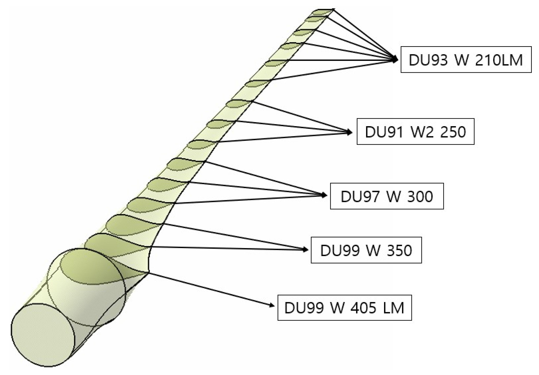
Figure 2 shows the aerodynamic design configuration. The optimal design was performed for each cross-section by applying the DU-series airfoil.
Aerodynamic performance analysis was carried out to examine whether or not the performance of the designed blade satisfies the design requirements. The results of the aerodynamic design include the chord length and twisting angle for each cross-section and airfoil data. Aerodynamic performance analysis was conducted based on these design data. The aerodynamic performance analysis was carried out using the aerodynamic design result suggested in
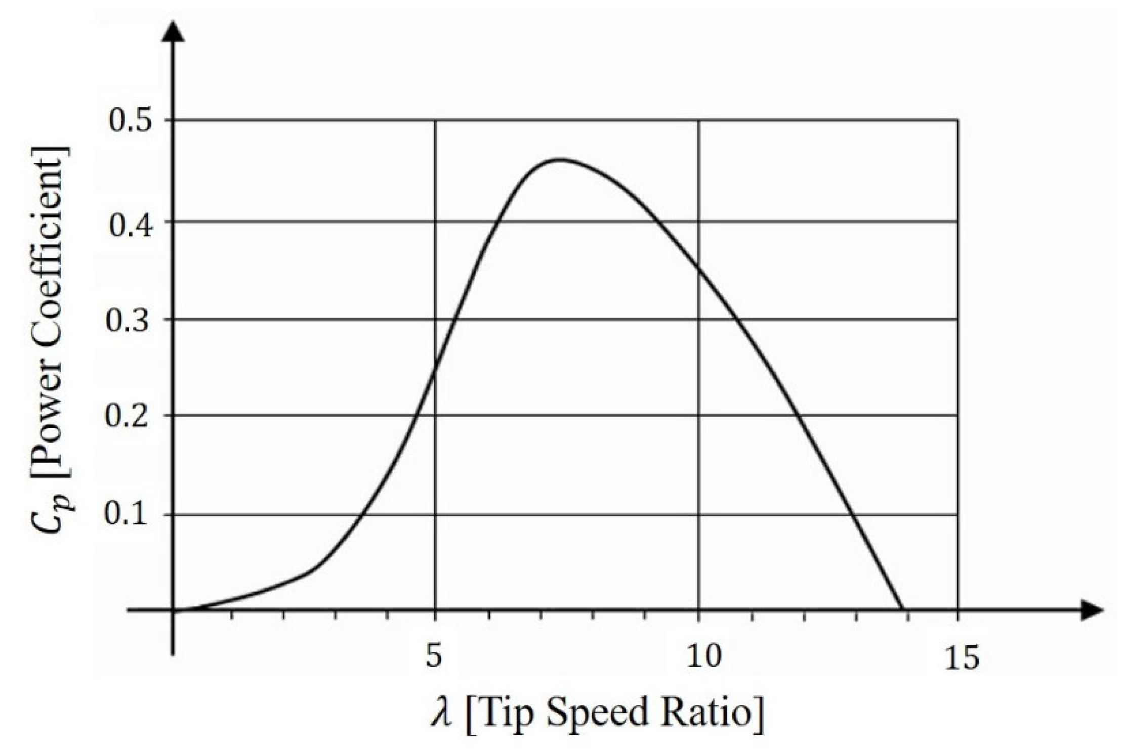
Table 2. The axial thrust, moment coefficients, and power coefficient were analyzed using the following equations. As a result of aerodynamic performance analysis, it was found that the performance coefficient had the maximum value of 7 for the tip speed ratio and decreased for other different tip speed ratios. Aerodynamic performance was theoretically calculated using the following equations, where
is rotor the radius and
means the length of the divided blade section. The power coefficient
was calculated using the following equation. The power coefficient calculated using the theoretical equation was compared with the power coefficient through a wind tunnel test.
means the axial thrust,
is the moment coefficient, and
is the area depending on the rotor diameter.
In this study, the performance coefficients of similar blades were used for comparison to verify the conceptual design results. For similar blades, the performance coefficient was measured according to the blade’s tip speed ratio determined in the wind tunnel tests.
Figure 3 shows the data for the power coefficient and tip speed ratio determined in the wind tunnel test. At 12.5 m/s of rated wind speed, mechanical and electrical powers were 29.81 MW and 28.32 MW, respectively; thus, it was confirmed that the aerodynamic design requirements for blades were met. The calculation result, which showed that power changed depending on the blade’s tip speed ratio, is presented in
Table 3. Therefore, we chose a multipole ring generator of 30 MW capacity. It is automatically disconnected from the grid at 14 m/s wind speed and immediately stopped either by a mechanical brake or by feathering its blade for a variable-pitch wind rotor.
Computational fluid dynamics (CFD) analysis was conducted to verify the theoretical result of the aerodynamic performance analysis. The aerodynamic design requirement was reflected to perform analysis modeling. A cylindrical area was set around the blade and set as the wind blew from left to right. Three blades were modeled to create a mesh around them. The constant inflow rate was set as the velocity boundary condition at the inlet area, and the constant pressure was set as the pressure boundary condition at the outlet area. The software used for the blade’s flow analysis was ANSYS 2022 R2. In this study, the influence of the nacelle or tower for aerodynamic analysis was not considered. Aerodynamic analysis was performed considering only the blade aerodynamic load.
The rotation of the rotor was set as follows: the ambient stationary domain and wind turbine rotating domain were separated. The rotation condition was applied to the rotating domain. The two domains set the interface using the frozen rotor model. Only aerodynamic analysis of the rotor blades was performed. The effect of the ground and tower on blade aerodynamics was not considered because the blade is quite high off the ground and the tower is behind the blade’s rotational surface. The lift and drag, which are loads that affect the blade, were previously verified with the power coefficient through blade element theory. CFD analysis was used only to verify the rated power performance.
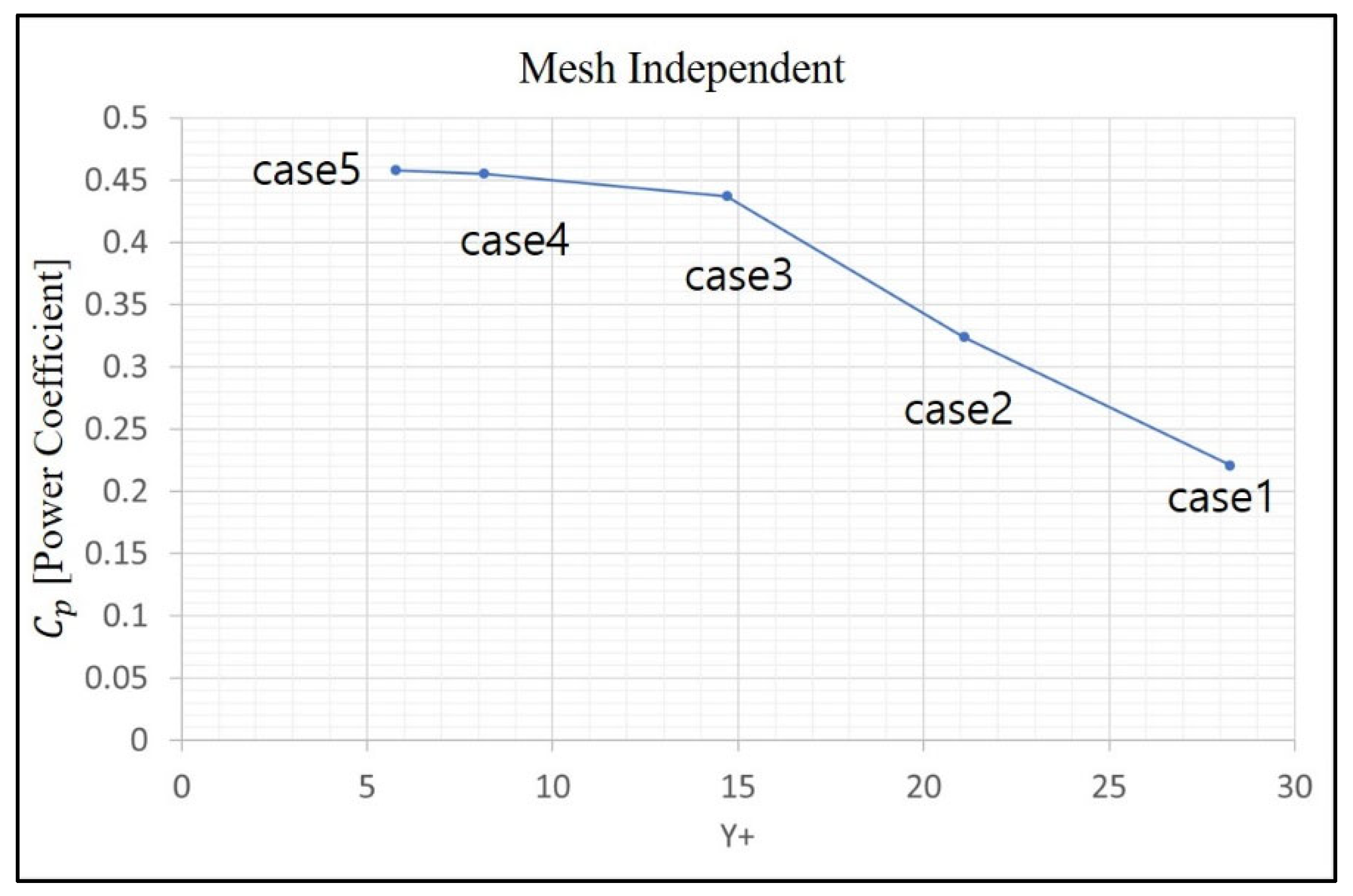
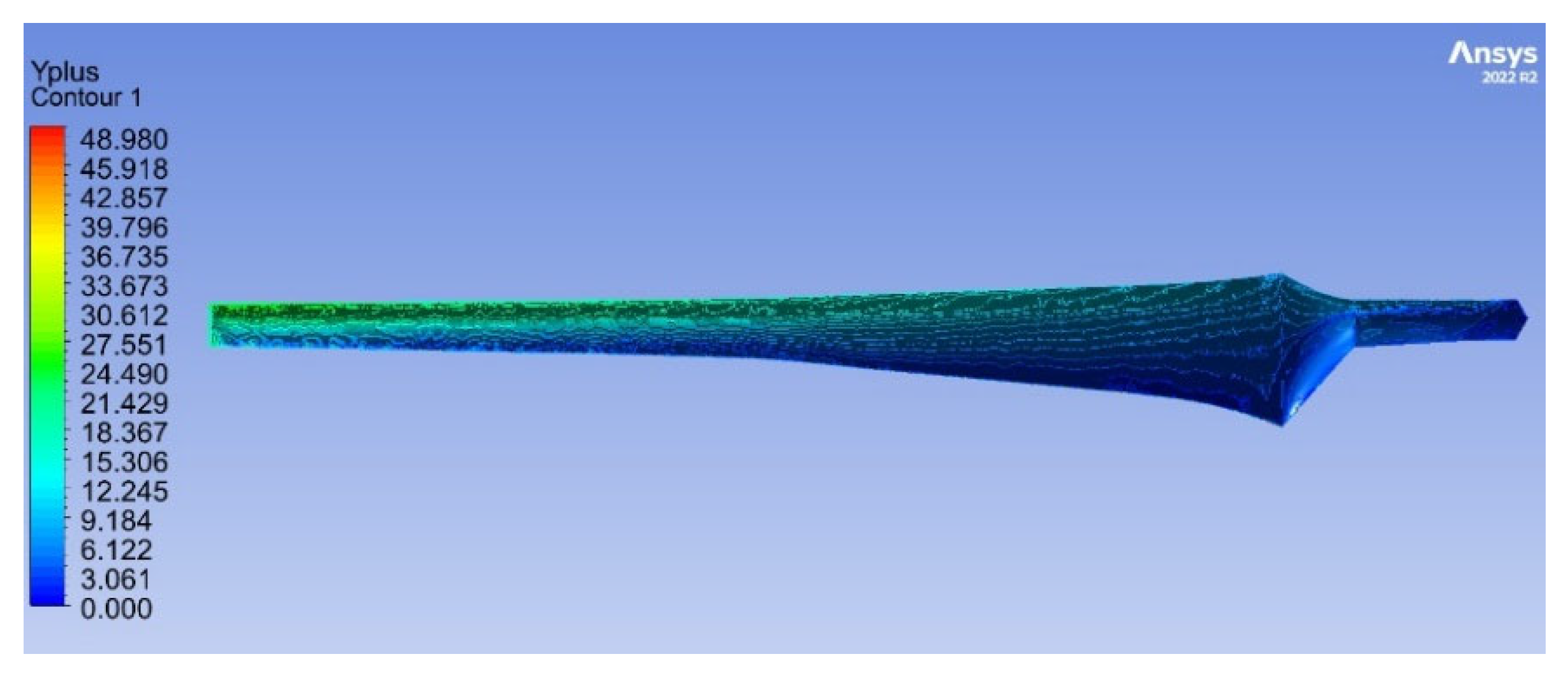
An atmospheric model composed of air and wind turbine models was constructed into grids for CFD analysis. The model was constructed as a periodic model for one blade model to save analysis time and resources. In particular, the atmospheric model was constructed with 10 times the blade length. This is for sufficient mixing of air after the blade rotates the disk. The wall surface of the model subject to analysis is the blade surface. Mesh sensitivity was reviewed based on y+. The mesh was constructed to be y+ < 50.
Table 4 shows the detailed boundary conditions for CFD analysis. For aerodynamic analysis, mesh independence was evaluated. The numerical analysis was performed for five cases based on Y+. As a result of evaluating the power coefficient, it was an appropriate mesh.
Figure 4 shows the result of mesh independence.
We analyzed the numerical analysis result for the 25 MW wind turbine blade designed. We examined the power result based on rotational speeds. The rated rotational speed was 6.4 rpm at 12.5 m/s, which is the rated wind speed. As a result of the analysis, this was found to indicate a power of 28 MW at the rated rotational speed. As a result of comparing the theoretical performance analysis results, it was therefore confirmed that the rated power produced similar results.
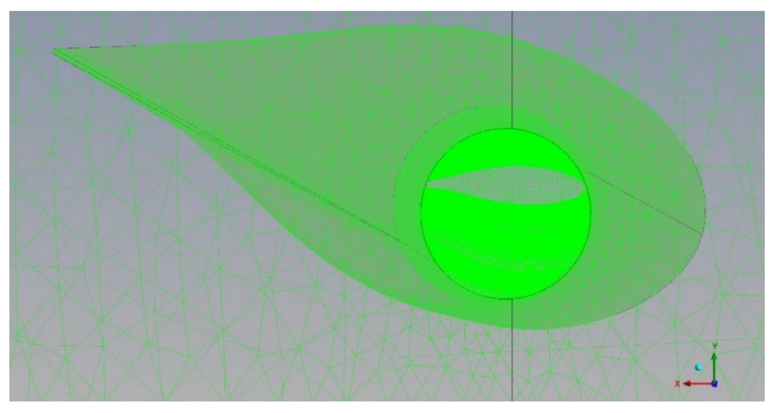
Figure 5 shows the boundary conditions for CFD analysis. The boundary mesh is shown in
Figure 6. The mesh generation of the blade surface is shown in
Figure 7.
Figure 8 shows the y+ contour of the blade surface and
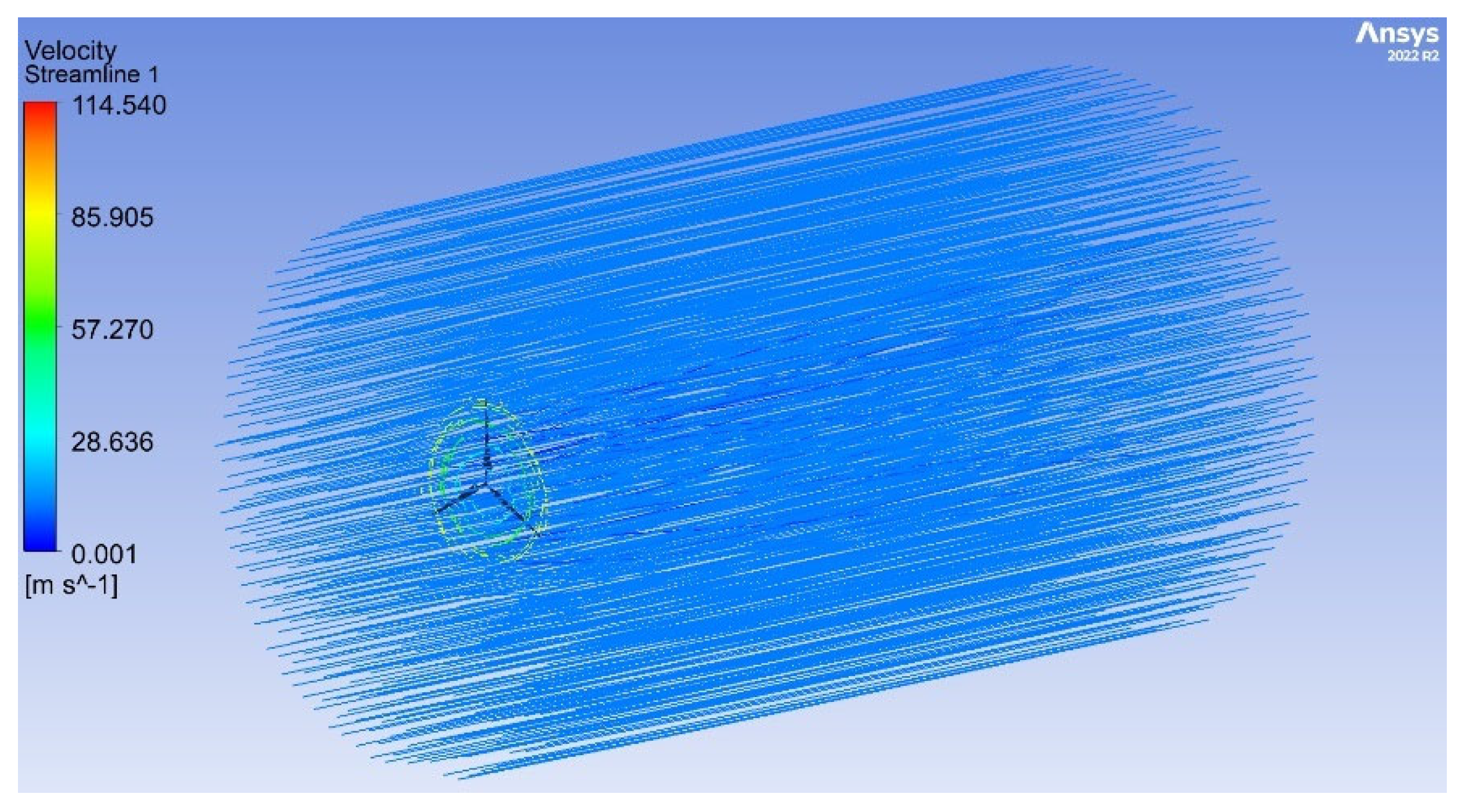
Figure 9 shows the pressure contour. The stream line based on numerical analysis is shown in
Figure 10.
This aerodynamic analysis was conducted by referring to the CFX analysis example for a general horizontal wind turbine. Total temperature and normal speed were set as inlet conditions for the wind turbine. The static pressure was applied to the outlet in the direction of airflow and the opening in the vertical direction. The k-Epsilon or SST was used in the turbulence model. In this work, the k-Epsilon model, which makes it easier to construct the grid, was used.
3. Structural Design and Analysis
In this study, the aerodynamic loading condition in
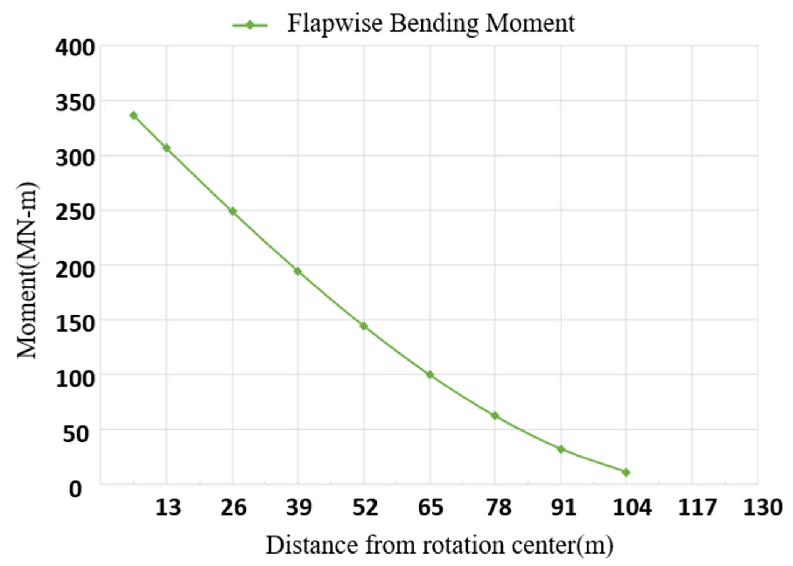
Table 5 was considered to simulate the loading condition defined for aerodynamic design. After dividing into three loading conditions, such as the rated wind speed condition (case 1), the cut-out wind speed one (case 2), and the storm one (case 3), it was confirmed that the aerodynamic load for case 1 was the largest load based on the loading analysis results based on aerodynamic force applying to each station. This is the case where gust is applied at the rated wind speed. Therefore, this was selected as the structural design load. The flap-wise shear forces F
n and bending moment M
n were calculated using the following equations.
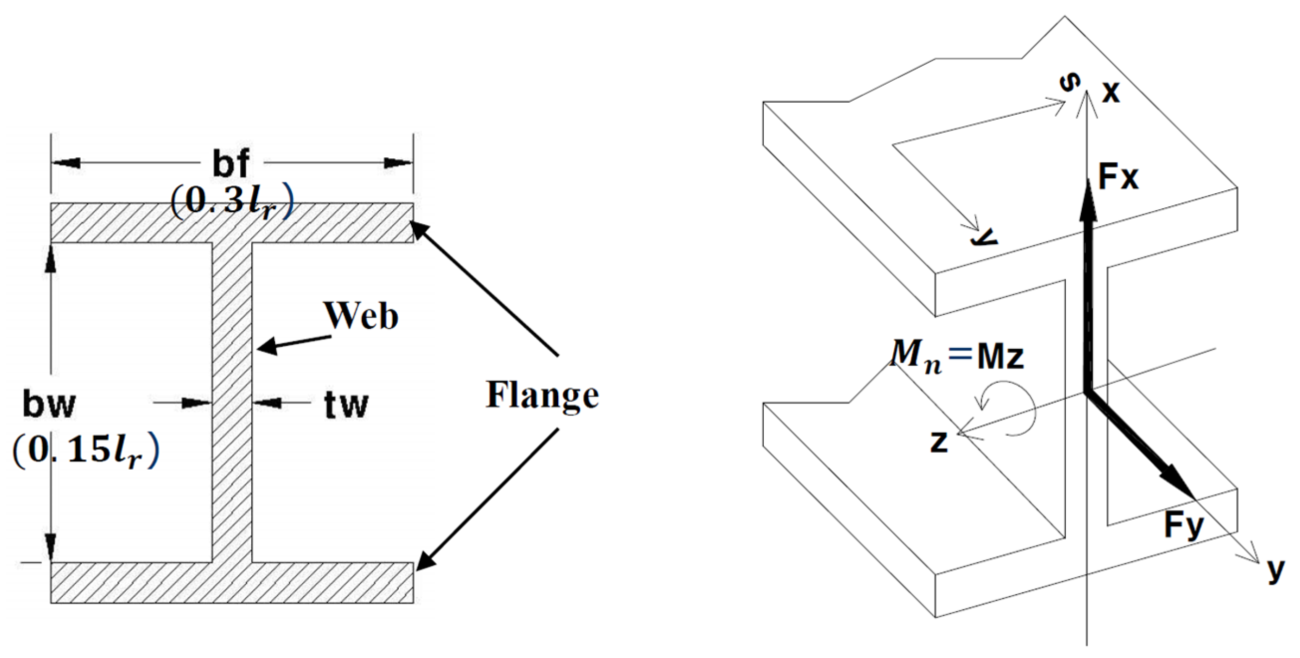
Figure 11 shows the bending moment diagram for the case 2 loading condition which is the most important of the design conditions.
There are some differences between the aerodynamic design loads and structural design loads. The aerodynamic load was calculated for aerodynamic configuration design. The aerodynamic loads were verified through aerodynamic analysis with CFD. The structural design load was recalculated by analyzing the aerodynamic load. The structural design was carried out based on bending force and moment.
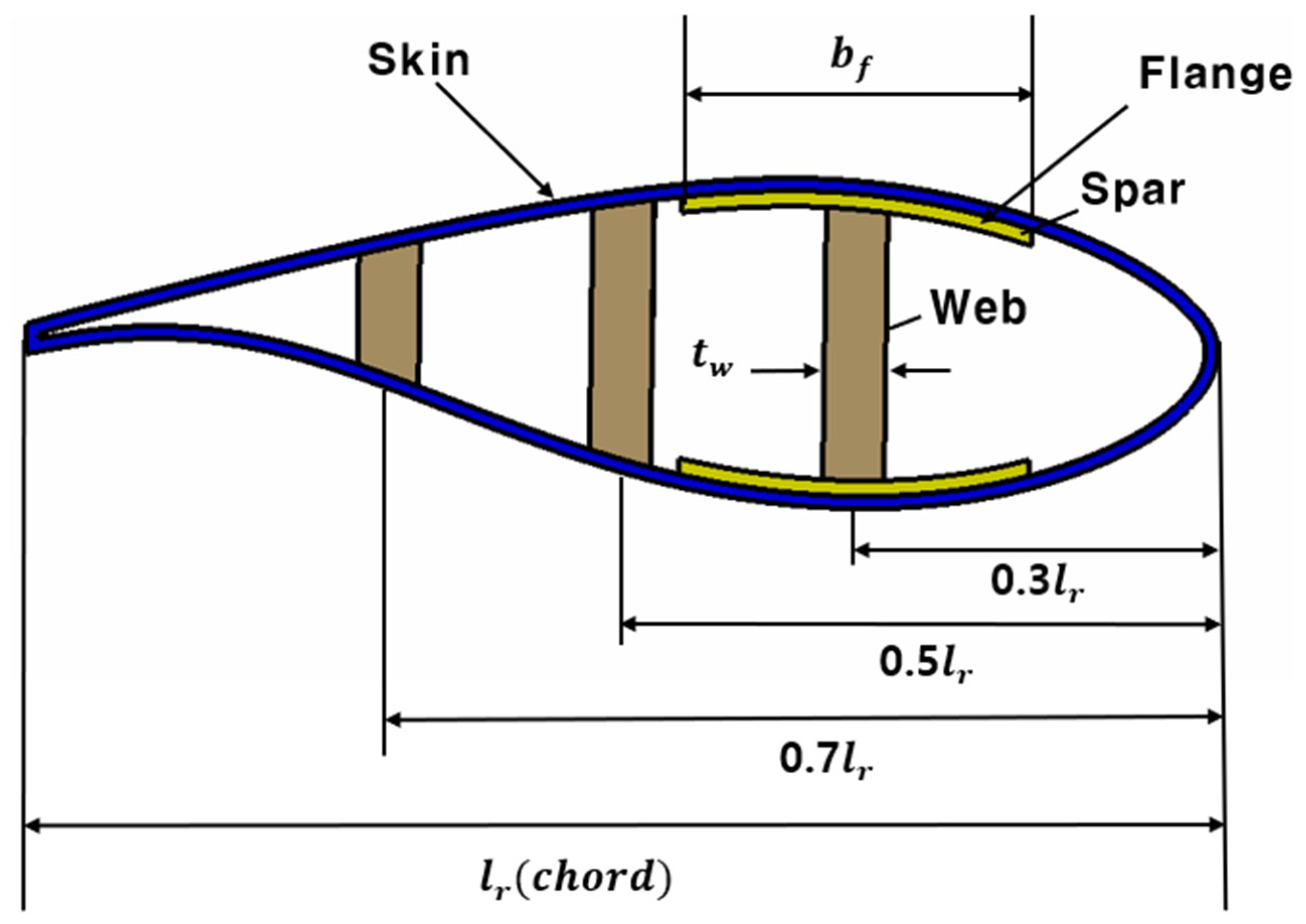
For the material of the blade used in this study, we applied a high-strength composite with outstanding structural intensity and fatigue life. For the spar that receives a principal bending load, we selected a carbon/epoxy UD laminate structure type. For the blade’s spar web, we applied a glass/epoxy laminate–foam core sandwich structure. The structural type is a multiple-cell semi-monocoque type for dividing the large flap-wise bending moment and the shear flow. For simplification of the conceptual design, only the flap-wise bending moment is considered for the spar flange and only flap-wise shear force is considered because the chordwise shear force and bending moment are relatively negligible. Only the shear flow is considered to design the blade skin. The specimen test was performed using the static material testing system NFEC-2007-10-001003 at the Future Mobility Platform Reliability Core Center at Kunsan National University.
Figure 12 shows the configuration of the blade’s cross-section for structural design.
For the initial structural design, a simple design technique (netting rule) was applied to the design under the assumption that only the fiber laminated in the loading direction was responsible for the load, and then the design was complemented through the rule of mixture. The rule of mixture is a theory that 10% of the strength of the fiber laminated in a direction different from the loading direction contributes to the loading direction so that there is no delamination in a composite designed using a simple design technique, which is a more lightweight design method than the simple design technique. The final design result was drawn by supplementing fibers of different directions to the fiber of 0° direction determined in the initial design. The initial structural design result was confirmed and then the design was improved through structural analysis.
After simplifying the basic structure of blade cross-sections into an I-beam configuration to determine the length of spar flanges and webs for each station, the netting rule and rule of mixture methods were applied to perform the design. The blade skin and web were designed considering weight lightening, shear stress, and buckling stability. The spar was applied in the 0° direction as it was responsible principally for the bending load. In addition, it was laminated symmetrically to remove the coupling stiffness effect. The buckling stability for initial design results was weak, so it was improved through design. In the initial design, it was designed without consideration of foam sandwich structures. However, the buckling stability was unstable. Therefore, foam sandwich structures were finally applied, so the design was improved.
Table 6 shows the mechanical properties of the composite material for structural design.
Table 7 shows the structural design result for each section.
4. Discussion
A summary of the initial design results is as follows. The flange thicknesses are designed variably at each radius r. For easy manufacturing, the web thicknesses are designed to be the same thickness of 14.5 mm. The number of flies is 116 plies. The stacking sequence is . The other two webs’ thicknesses are assumed as half of the main spar web’s thickness. The aerodynamic load was distributed to the spar location. The main spar web carries 50% of the load. Each other spar web carries a 25% load. Therefore, the thickness of the other web was designed to be half that of the main spar web. The thickness is 7.25 mm. The number of flies is 58 plies. The stacking sequence is . The skin thicknesses are designed to be the same thickness of 6.6 mm. The number of flies is 44 plies. The stacking sequence is . The load and torque were simplified by dividing into 10 sections for blade design. The effect of simplification was supplemented through numerical analysis. The conceptual design result will be modified in a detailed design.
Structural analysis was performed on the initial design results. The configuration of the major load acting on the spar section is shown in
Figure 13. The stress check is performed first using classical laminate theory. The maximum flange thickness location of
Section 4 is expected to be the highest stress point. The safety factor of the flange in
Section 4 is calculated using the classical laminate theory program. The last ply failure and safety factor are calculated using maximum stress failure criteria. The load intensities of the flange and web were calculated using the following equations. The effective section axial stiffness and equivalent isotopic section modulus were considered. The effective section bending stiffness and equivalent section isotropic second moment of the area were calculated. The safety factor of the spar flange is 13.7. The safety factor of the spar web is 10.8. After confirming structural safety, structural stability was investigated. The engineering sciences data unit was used.
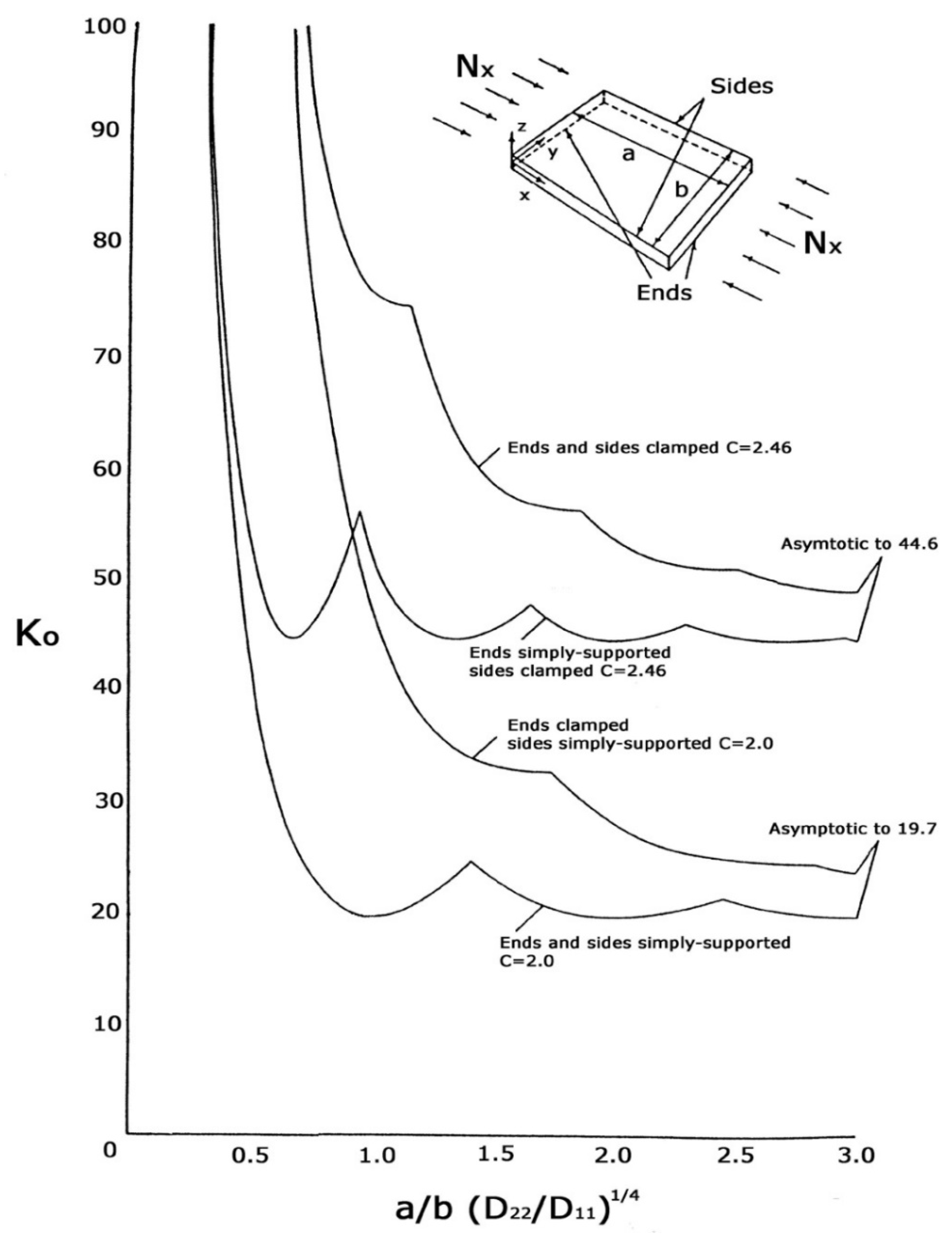
Figure 14 shows the buckling analysis regulation of ESDU 80023, where the D matrix means the bending stiffness, D
11 is the
x-axis bending stiffness, and D
12 is the
y-axis bending stiffness. However, the safety factor of structural stability about the flange is 0.39. The safety factor of structural stability of the web is 0.03. The structural stability is unstable. It was confirmed that buckling problems may occur. Therefore, the flange should be modified. A foam sandwich structure type was considered to prevent buckling. Foam of 30 mm thickness was applied to the flange. Also, a foam sandwich structure with 50 mm thickness was applied to the web. After improving the structural design results, structural stability was reviewed again. The safety factor of structural stability of the spar flange and web is 1.67. Therefore, the structural design was finally completed with a foam sandwich composite structure.
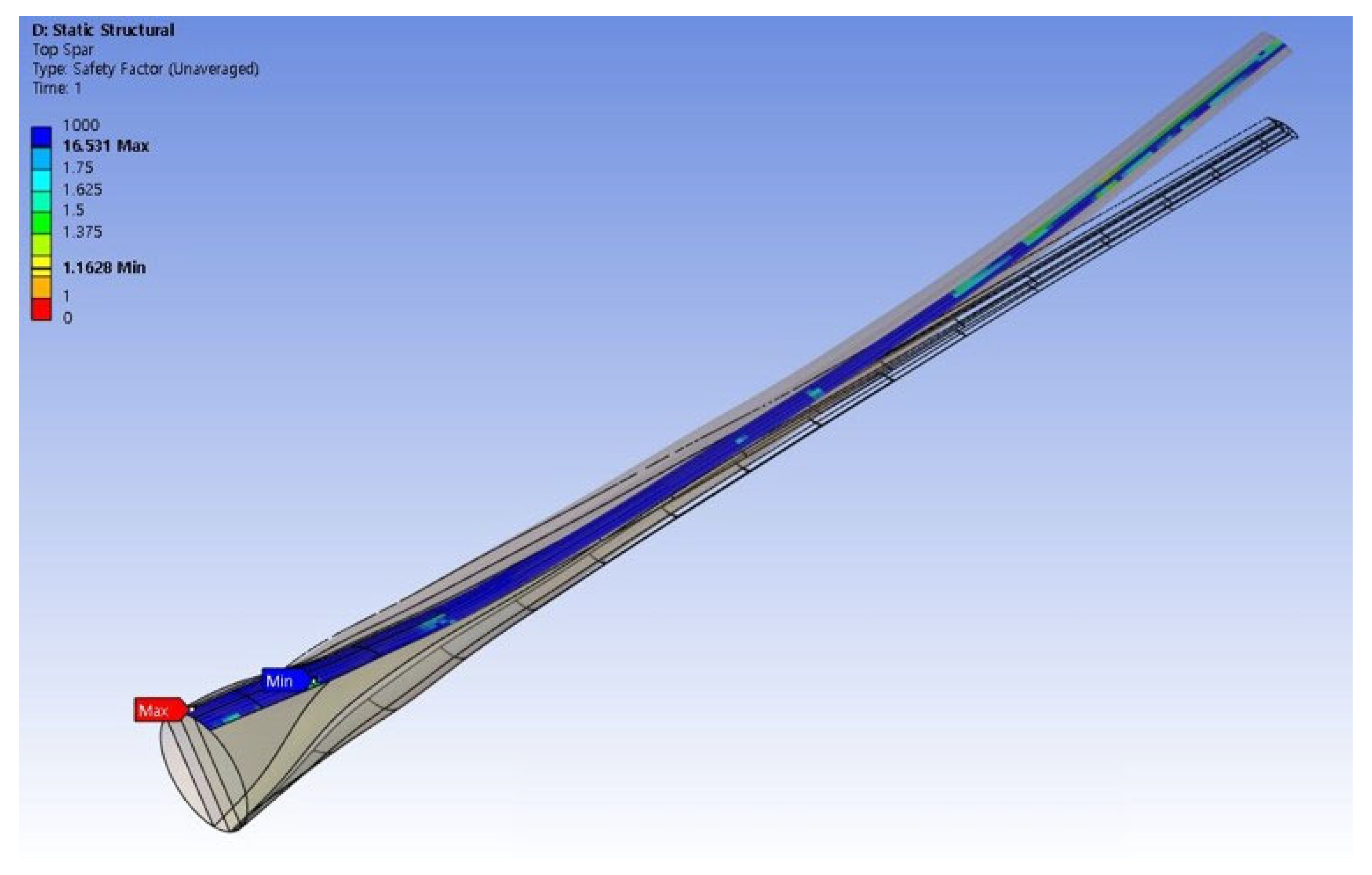
Table 7 shows the final structural design result of the main spar flange. Finally, structural analysis was performed using the finite element method. The finite element program used for structural analysis is a commercial code ANSYS 2024. A distributed load was applied along the blade length. The boundary condition was applied to the joint area as a fixed boundary condition.
Figure 15 shows the structural analysis result of the spar flange. In this analysis, linear static stress analysis and deformation analysis were carried out. The structural design results were found to be safe. Jang et al. performed a study on the design of a 20 MW class blade system. They developed a blade mass model and implemented it in the design of a 20 MW system [
5]. This research team developed a 25 MW system by comparing it with previous research results.


