Communication

Augmented MIMO: Body-Mounted Antennas for Tiny Wearable Devices

School of Systems Engineering, Kochi University of Technology, Kochi 782-8502, Japan
Appl. Sci. 2025, 15(2), 557; https://doi.org/10.3390/app15020557
Submission received: 15 December 2024 / Revised: 3 January 2025 / Accepted: 7 January 2025 / Published: 8 January 2025
(This article belongs to the Section Electrical, Electronics and Communications Engineering)

Abstract

:
Multiple-input–multiple-output (MIMO), which uses multiple antennas at the transmitter and receiver, is now an essential technique for increasing communication capacity without widening the occupied radio bandwidth. However, antenna arrays within a deep subwavelength dimension degrade MIMO performance due to mutual coupling between the antenna elements. In particular, very small devices such as smartwatches encounter this problem. To address this, we propose Augmented MIMO, mounting a larger antenna array on the human body, for small wearable devices. The experimental results demonstrate throughput improvement with the proposed scheme, even if the overall antenna gain decreases with external body-mounted antennas. This work contributes to the future development of yet another scheme to improve the communication performance of small wearable devices—using the human body as a spacious antenna fixture.

1. Introduction

Multiple-input–multiple-output (MIMO) [1], which uses multiple antennas at the transmitter and receiver, is now a common technique for increasing communication capacity without widening the occupied radio frequency (RF) bandwidth. A physical limitation of MIMO is that its effectiveness in improving channel capacity depends on the spatial correlation of the antennas. As a rule of thumb, a half-wavelength separation between antenna elements is required for sufficient antenna independence.
Antenna arrays within a deep subwavelength dimension degrade MIMO performance due to the increased mutual coupling and spatial correlation between the antenna elements [2]. In particular, very small devices such as smartwatches encounter this problem. The 2.4 GHz industrial, scientific, and medical (ISM) band is widely used for a variety of wireless communications, including wireless local area networks (WLANs) and Bluetooth, which are used in most commercially available wearable devices. The free-space wavelength of radio waves in the band is about 12 cm. Therefore, the antenna array that can be embedded in wearable devices with a watch form factor or smaller must be of deep subwavelength. Without special antenna decoupling techniques, it has been reported that typical inverted-F antennas integrated into a 40 mm square scale, comparable to smartwatches, exhibit a mutual coupling of about 15 dB [3]. To counter this problem, antenna decoupling techniques have been extensively investigated [4].
Despite such a challenging issue, it has been clarified in the literature that even if the antenna spacing is reduced, increasing the number of antenna elements contributes to increasing the channel capacity [5]. In addition, one of the key technologies for next-generation high-speed mobile networks is massive and ultra-massive MIMO [6]. Thus, MIMO is an essential technology for mobile communication devices. The application of MIMO technology is also expanding to smaller scales; for example, investigations of implantable antennas [7] and antenna-on-chip [8] are in progress. Therefore, for the sustainable evolution of mobile wireless communication technologies, a wearable-friendly MIMO implementation technique is needed.
We propose Augmented MIMO, in which a larger antenna array with increased antenna spacing is mounted on the human body, to improve the MIMO performance of wearable devices with a physically constrained small form factor. The key idea is that, for such very small wearable devices, the wearer’s own body can be used as a spacious antenna fixture that always exists with oneself. Assuming the use of the 2.4 GHz ISM band, the human body is significantly larger than the wavelength. Therefore, the proposed scheme even opens avenues to implement massive MIMO antenna arrays with wearable devices, whose implementation is currently limited to base stations that have enough space to accommodate the large number of antennas.
It must be clarified that the proposed scheme is completely different from, but not exclusive to, other antenna decoupling techniques. We can find extensive research on this type of coupling reduction in size-limited MIMO applications [4]. The state-of-the-art developments include isolation techniques based on additional parasitic elements [9], characteristic modes [10], electromagnetic band gap (EBG) [11], and metamaterials [12]. The proposed Augmented MIMO scheme provides a way to implement MIMO antenna arrays with sufficient spacing and reduced antenna coupling without relying on special decoupling techniques. On the other hand, when combined with decoupling techniques, the antenna density can be increased; therefore, the total number of antenna elements that can be implemented in clothing is significantly increased, thus paving the way for the implementation of massive MIMO systems in wearable devices.
An example of Augmented MIMO implementations, in contrast to conventional MIMO, is illustrated in Figure 1. Here, we consider a MIMO link between a WLAN access point (AP) and a smartwatch. Two small chip antennas are embedded in the smartwatch, with a subwavelength spacing and, therefore, degraded antenna isolation. In the conventional MIMO system in Figure 1a, 2 × 2 MIMO channels are established between the two chip antennas and two AP antennas. On the other hand, in the Augmented MIMO system shown in Figure 1b, the dominant multipath MIMO channels are between the two shoulder-mounted antennas and two AP antennas. At the opposite end of the signal paths on the clothing, near the smartwatch, the signal is transferred between two pairs of proximity-coupled chip antennas. Each pair consists of one antenna belonging to the watch and the other to the clothing. Note that the chip antennas in the smartwatch are identical in both Figure 1a,b. Therefore, Augmented MIMO only adds the antenna elements and signal paths with better isolation on the clothing, without disabling anything in the original antenna system.
A critical argument that arises with the Augmented MIMO system is whether MIMO performance is indeed improved, even with the closely spaced original MIMO antennas remaining in the signal paths. These antennas may reduce the rank of the MIMO channel, similar to a keyhole effect [13], which degrades the MIMO channel capacity due to a rank-1 signal propagation section. The main contributions of this paper are (1) to introduce the idea that wearable antennas can be used to improve the MIMO performance of small wearable devices; (2) to present specific experimental results that support the validity of the idea, even if the device itself is not directly embedded/attached to clothing and is originally designed to operate in a standalone manner; and (3) to point out the factors that influence its effectiveness as a guide for future research.
In this paper, we empirically demonstrate the improvement in MIMO performance with a prototype of Augmented MIMO. In addition, several factors that influence the effectiveness of Augmented MIMO are discussed. The discussion will provide insight into the extensive work that can be conducted in the future on Augmented MIMO.

2. Principle: How Augmented MIMO Improves Channel Capacity

Here, we consider an N × N Augmented MIMO system, i.e., we assume an equal number N of transmitter antennas and receiver antennas. Figure 1b is an example of N = 2 . The channel capacity depends on the signal-to-noise ratio (SNR) at the receiver and the channel correlation. When the channel state information is not shared between the transmitter and receiver, the channel capacity C (per unit bandwidth) is formulated as [1]
C = log 2 det [ I N + ρ N H H ] = k = 1 N log 2 ( 1 + ρ N λ k ) ,
where ρ denotes the average SNR at each receive antenna, H represents the channel, H is its conjugate transpose, and λ k are the non-negative real eigenvalues of the Wishart matrix W H H . I N is the N × N identity matrix. For higher channel correlations, each of the λ k values decreases. When one of the eigenvalues becomes significantly smaller than the others and is practically considered to be zero, the rank of W decreases, i.e., the number of terms actually summed in (1) decreases.
The idea of Augmented MIMO is to avoid a λ k reduction due to closely spaced antennas by extending the substantive locations of the MIMO antennas outside the small device itself. Therefore, Augmented MIMO is expected to improve the channel capacity of a wearable MIMO transceiver that faces mutual antenna coupling due to its size limitation. Note that it is not expected to be effective for MIMO systems that originally achieve large eigenvalues.

3. Augmented MIMO Hardware Prototype

3.1. Two-Element MIMO Antenna Array in Watch Form Factor

A two-element antenna array was fabricated in a watch form factor for a well-controlled experiment, instead of using commercially available smartwatches as a black box. The array consisted of two chip antennas, TSA5N18D2G45NV001T (Taiyo Yuden, Tokyo, Japan), and 8.2 nH series inductors for matching. These components were soldered on an FR-4 printed circuit board (PCB), as shown in Figure 2a. The antenna locations were determined as to be best positioned diagonally to maximize the antenna spacing within the watch-size PCB. The PCB pattern artwork and matching inductor were determined according to the recommendations in the antenna datasheet [14]. The antenna efficiency and maximum gain are 74% and 2.8 dBi, respectively, according to the datasheet. The onboard miniature coaxial connectors, U.FL receptacles (Hirose, Kanagawa, Japan) [15], allow the antenna array to be connected to a vector network analyzer (VNA) to measure scattering parameters (S parameters) and to an external WLAN transceiver for measuring throughput.
The measured reflection at port 1, S 11 , and transmittance from port 1 to 2, S 21 , are shown in Figure 2b. The isolation between the two coaxial ports was 14 dB, i.e., the transmittance | S 21 | from port 1 to 2 was 14 dB. An antenna spacing of 20 mm, less than half the wavelength, results in a low isolation.
From the measured S parameters, we can calculate the envelope correlation coefficient (ECC), a crucial parameter to evaluate the MIMO diversity performance of the antennas [16]:
ECC = S 11 S 12 * + S 21 S 22 * ( 1 | S 11 | 2 | S 21 | 2 ) ( 1 | S 22 | 2 | S 12 | 2 ) η 1 η 2 ,
where * represents the complex conjugate, η 1 and η 2 are the efficiencies of the two antennas, and zero correlation of antenna losses was assumed. From the measured S parameters and η 1 = η 2 = 74 % [14], | ECC | was calculated as 0.21 at 2.45 GHz. The calculated ECC is acceptably low but is an order of magnitude, or more, higher than that of antennas designed using state-of-the-art antenna decoupling techniques [4].
The antenna array PCB was fixed onto a watch face after the removal of the watch’s internal components, as shown in Figure 3. For the ease of the experiment, the PCB was attached outside the watch face, not inside it.

3.2. Augmented MIMO Clothing

A prototype of Augmented MIMO clothing was created by attaching an antenna array PCB to the cuff near the watch and two shoulder antennas, as shown in Figure 4. The shoulder antennas are a commercially available flexible printed circuit (FPC) antenna, 1461530050 (Molex, Lisle, IL, USA). According to the antenna datasheet, the antenna efficiency and maximum gain are 78% and 3.2 dBi, respectively [17]. From the measured S parameters between the two shoulder antennas, whose frequency characteristics plot is omitted here, the ECC was calculated to be less than 0.01 at 2.45 GHz. The 30 cm antenna spacing, which is significantly larger than the wavelength, results in a low ECC. Therefore, it is expected that MIMO performance can be significantly improved by using the shoulder antennas. Note that the ECC calculated here is based on the S parameters measured only between the shoulder antennas, not including the proximity coupling paths of the watch and cuff antennas.
For the ease of conducting the experiment, the PCB identical to the watch PCB shown in Figure 2a was also used as the cuff PCB. The cuff antennas and shoulder antennas are connected with RG-174 flexible coaxial cables. The preliminarily measured insertion loss of the cable was 2.0 dB. The total weight increase of the clothing with antennas and cables was about 40 g.
The cuff PCB was aligned and fixed to the watch PCB by magnet fixtures without any translational and rotational misalignment, as shown in Figure 5a. Considering a practical use case, a few millimeters’ distance between the PCBs is reasonable, since these PCBs are separated by at least the watch housing. Thus, the PCB distance was determined as 3 mm. Note that, in the experiment, the watch PCB was not embedded inside the watch housing, but was mounted outside the watch for simplicity.
The antenna port numbers are defined as shown in Figure 5a. The measured transmittance from the watch antenna #1 to the nearest cuff antenna #3, | S 31 | , was 6.8 dB at 2.45 GHz, as shown in Figure 5b. Due to the closer antenna spacing, the proximity coupling was stronger than the intra-PCB antenna mutual coupling, i.e., | S 31 |   >   | S 21 | . This design, with the distance between the watch and cuff antennas being shorter than the 20 mm intra-PCB antenna distance, aimed to achieve | S 31 |   >   | S 21 | to increase the contribution of shoulder-mounted antennas. When | S 31 |     | S 21 | , the strength of the signal transmitted/received at one of the watch antennas through the shoulder-mounted antenna is significantly weaker than the signal “forwarded” from the other watch antenna through the unwanted mutual coupling.
In the experiments above and in the throughput measurements in the following section, the distance between the watch PCB and the cuff PCB was fixed at 3 mm. In practical use cases, depending on the design of the watch and cuff antennas, the proximity coupling | S 31 | can be further increased by decreasing the PCB spacing. The measured | S 31 | dependence on distance is shown in Figure 6. The | S 31 | achieved 3.7 dB at the maximum.

4. Augmented MIMO Throughput Evaluation

4.1. Line-of-Sight Environment

The throughput in the Augmented MIMO prototype system was measured with IPerf2 [18] installed on a pair of Windows PCs, as shown in Figure 7. Although IPerf2 measures transmission control protocol (TCP) throughput but not physical layer bandwidth, it is appropriate for this experiment to demonstrate the practical throughput improvement with Augmented MIMO. IPerf2 is an open-source tool that has been reported to be the most widely used network traffic generation tool over a 13-year period from 2006 to 2018 [19]. To the best of the author’s knowledge, such a universal and non-proprietary tool trusted by the research community for measuring throughput in the lower physical/network layers is not provided.
In Figure 7, one of the PCs is the IPerf server (receiver), and the other is the client (transmitter). The server is connected to one of the gigabit Ethernet ports of an IEEE 802.11ac-compatible WLAN router using a category-6 Ethernet cable. On the client side, an IEEE 802.11ac-compatible WLAN transceiver dongle is connected directly to a universal serial bus (USB) 3.1 port of the PC. Two detachable whip antennas are removed from the dongle, and two chip antennas are connected to the dongle with coaxial cables.
The experiments were conducted in a conference room in a university building. In this scenario, the channel includes the LOS path, as shown in Figure 7b. The WLAN connection was configured to operate in the 2.4 GHz band only, not in the 5 GHz band. The AP was configured to use channel 6 in the 2.4 GHz band, centered at 2.437 GHz, and the bandwidth was fixed at 20 MHz to avoid throughput fluctuations due to automatic channel width selection. With a channel width of 40 MHz, the throughput fluctuates significantly due to interference from other WLAN links in the vicinity of the experimental system.

4.2. Non-Line-of-Sight Environment

Measurements for another scenario, in a non-line-of-sight (NLOS) environment, were conducted in a larger laboratory room in the same university building, as shown in Figure 8. The distance between the WLAN router and the client was increased to 8.8 m. The direct path was blocked by a 1.8 m × 1.0 m whiteboard. Due to the furniture in the room, including desks and stools, it was a highly scattered environment.
The PCs, WLAN router/dongle, and IPerf settings used were the same as in the LOS environment experiment.

5. Results

5.1. Line-of-Sight Environment

The results of the throughput measurement in the LOS environment with the IPerf TCP mode are shown in Figure 9. The measured throughput was, at most, about 110 Mb/s, which is significantly lower than the throughput of the gigabit Ethernet between the WLAN router and the server PC, and of the USB 3.1 interface between the WLAN dongle and the client PC. Therefore, the measured throughput can be considered as a representation of the throughput of the WLAN air interface.
For the chip-to-AP link and the Augmented MIMO link, three trials each were performed in alternating order to verify the reproducibility of the measurement. In each trial, the throughput was measured 100 times at 1 s intervals. The 100 s measurement time was determined based on the periodic throughput fluctuations observed in the preliminary measurements. The fluctuation period was about 30 s, as can be seen in Figure 9, so the measurement time was set to be sufficiently longer than the fluctuation period.
The measured throughput of the chip-to-AP link was 32.4 Mb/s, 33.8 Mb/s, and 31.8 Mb/s on average for each trial. On the other hand, three trials with Augmented MIMO achieved average throughputs of 65.1 Mb/s, 65.7 Mb/s, and 79.7 Mb/s. Thus, Augmented MIMO increased the throughput by a factor of 2 or more on average.

5.2. Non-Line-of-Sight Environment

The results of the throughput measurement in the NLOS environment are shown in Figure 10. For the chip-to-AP link and the Augmented MIMO link, three trials of 100 s each were performed in alternating order, as in the LOS scenario measurement.
The measured throughput of the chip-to-AP link in the line-of-sight (LOS) environment was 27.5 Mb/s, 24.7 Mb/s, and 23.9 Mb/s on average for each trial. Augmented MIMO achieved average throughputs of 33.3 Mb/s, 34.2 Mb/s, and 43.4 Mb/s. Thus, Augmented MIMO increased the throughput by a factor of about 1.5 on average in the NLOS environment.

6. Discussion

6.1. Antenna Gain and Antenna Correlation

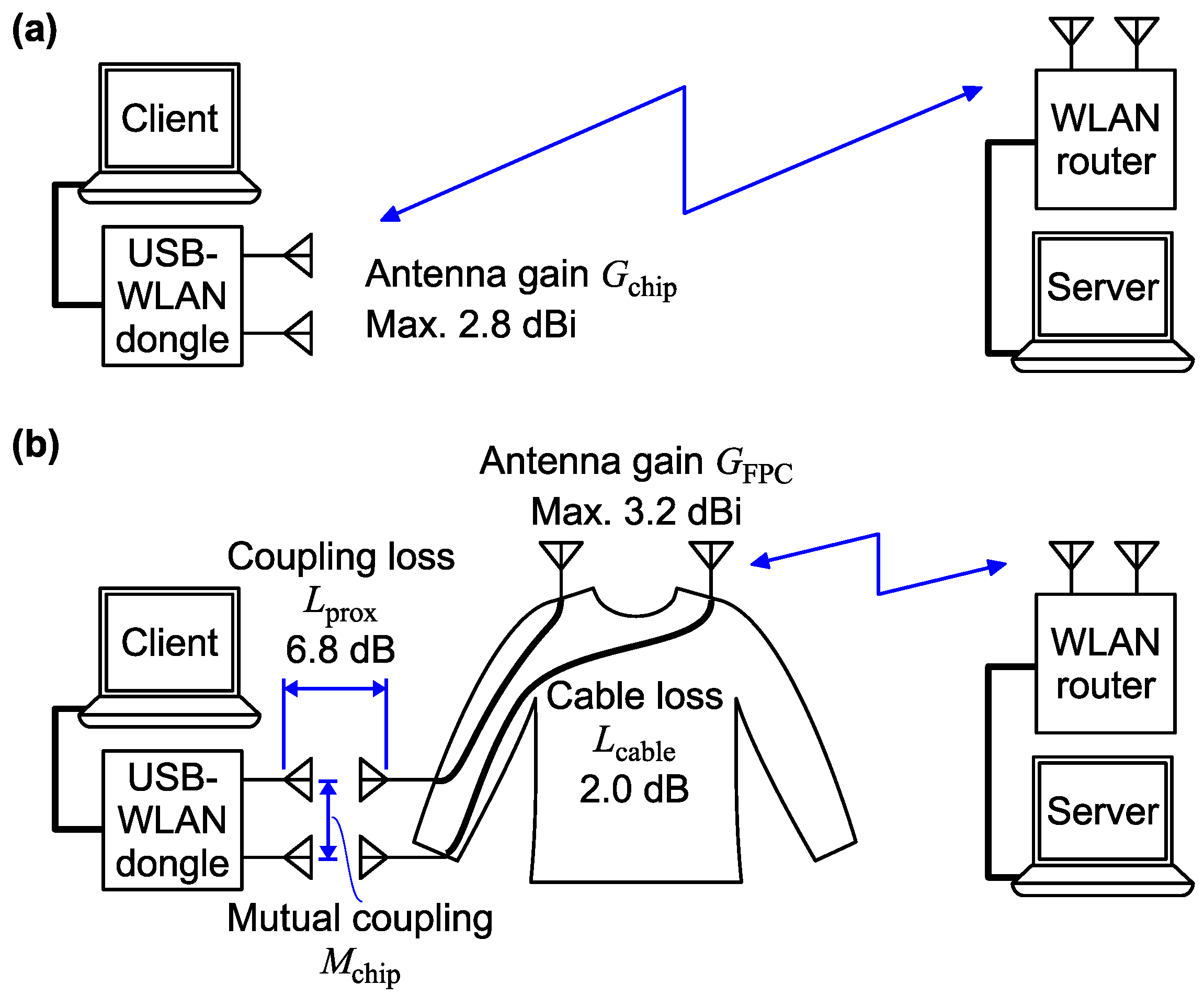
The antenna gains and losses in the chip-to-AP link and the Augmented MIMO link of our experiment are depicted in Figure 11.
Taking the losses into account, the overall gain of each antenna of Augmented MIMO is formulated in dB as follows:
G augmented = G FPC L prox L calbe .
In the experiment, L prox 6.8 dB, and L calbe 2.0 dB at 2.45 GHz. Although G FPC and G chip depend on direction and polarity, the maximum values of these gains shown in the datasheets [14,17] are approximately 3 dBi and roughly equal. Therefore, we assume G FPC G chip , and then, G augmented becomes approximately 9 dB lower than the original chip antenna gain G chip . Despite the reduced antenna gain, i.e., G augmented < G chip 
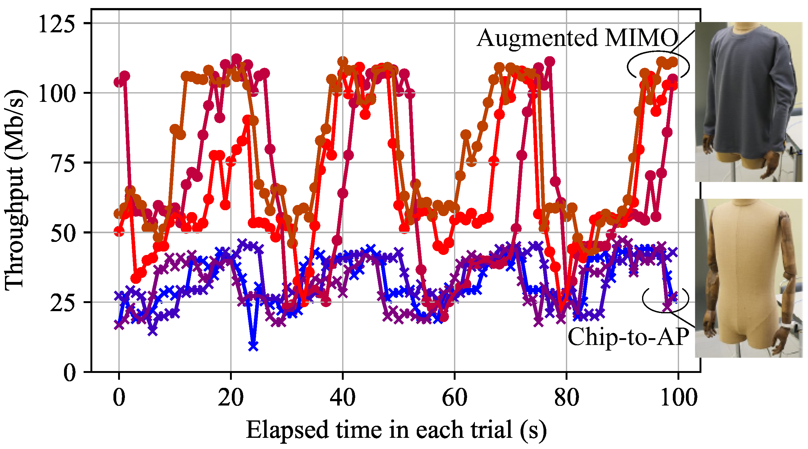
, the throughput was significantly improved by a factor of 2 or more in the LOS environment.
Assuming a constant noise level, the received signal strength determines the SNR; then, the antenna gain determines the SNR for a fixed transmit power. Decreasing the overall antenna gain with Augmented MIMO reduces the SNR at the receiver.
The channel capacity depends on the SNR at the receiver and the channel correlation, as described in Section 2. The experimental system is the case of N = 2 in (1). Higher channel correlations reduce λ 1 and λ 2 , which can cause the rank of W H H to be 1. Lower antenna gains reduce the SNR ρ at the receiver. Hence, whether antenna gain or antenna correlation is dominant depends on other factors.
The experiment results of increased throughput indicate that the increase in λ k in (1), i.e., the antenna correlation reduction, contributed more than the reduction in SNR ρ 
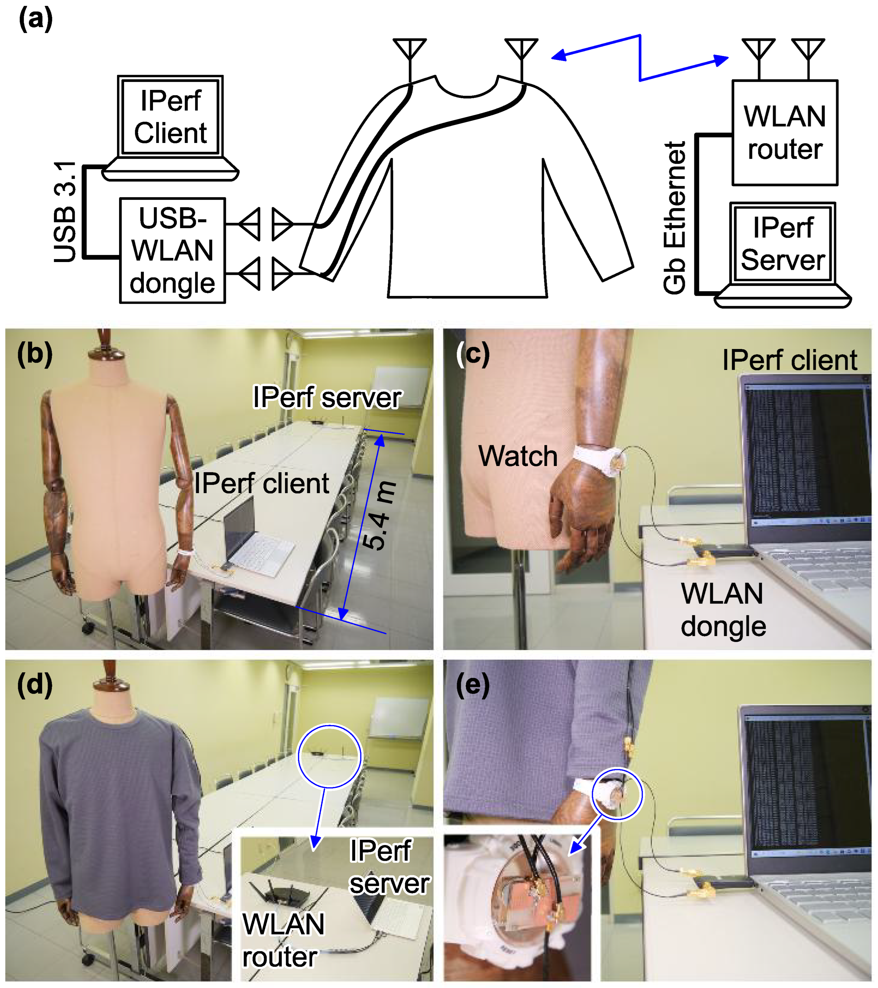
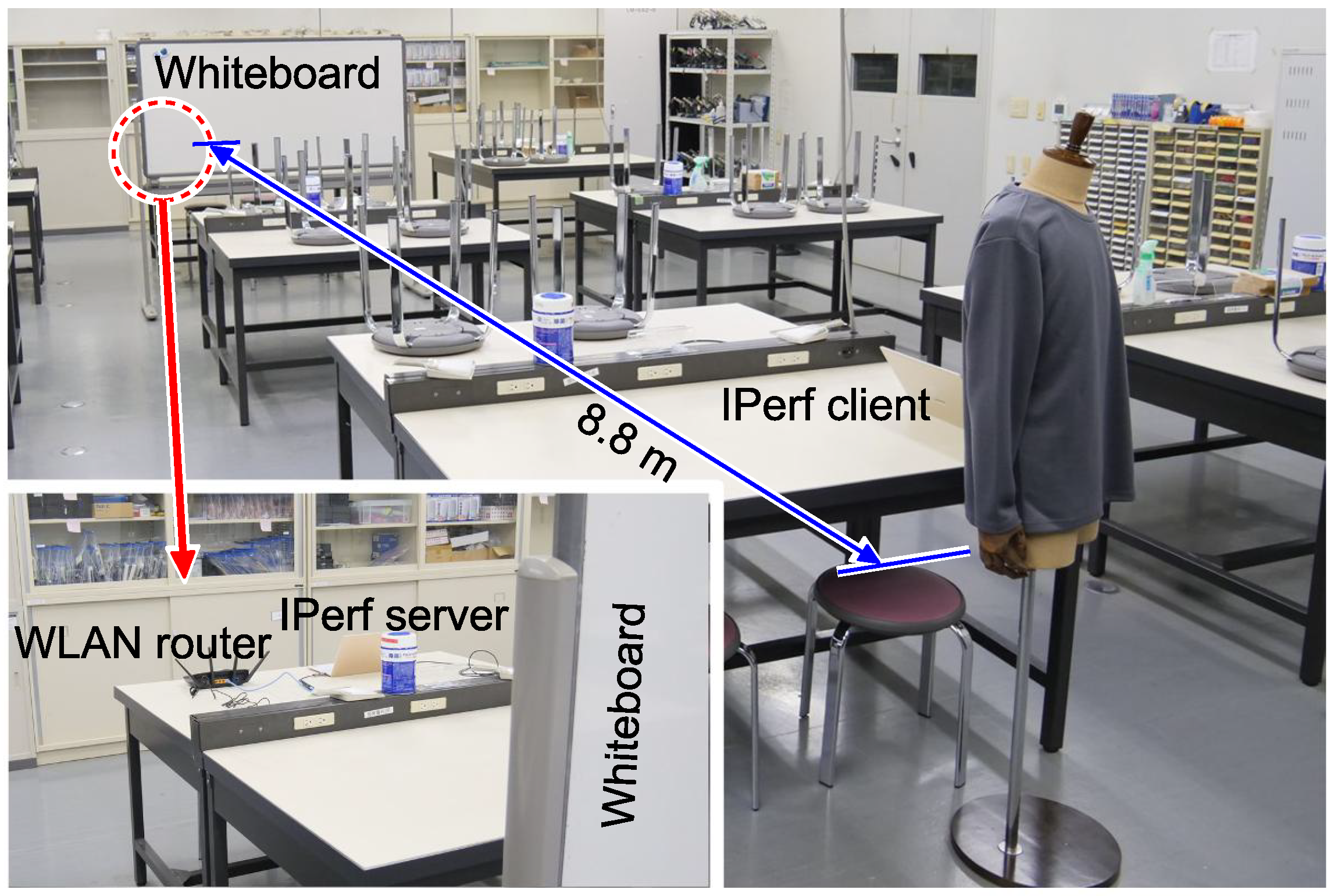
. The distance between the transmitter and the receiver was relatively short, 5.4 m, and the channel included the LOS path as shown in Figure 7b; therefore, the SNR may have been relatively high for both chip-to-AP and Augmented MIMO compared to typical WLAN use cases. This high SNR condition may have reduced the influence of the antenna gain reduction in the Augmented MIMO link.
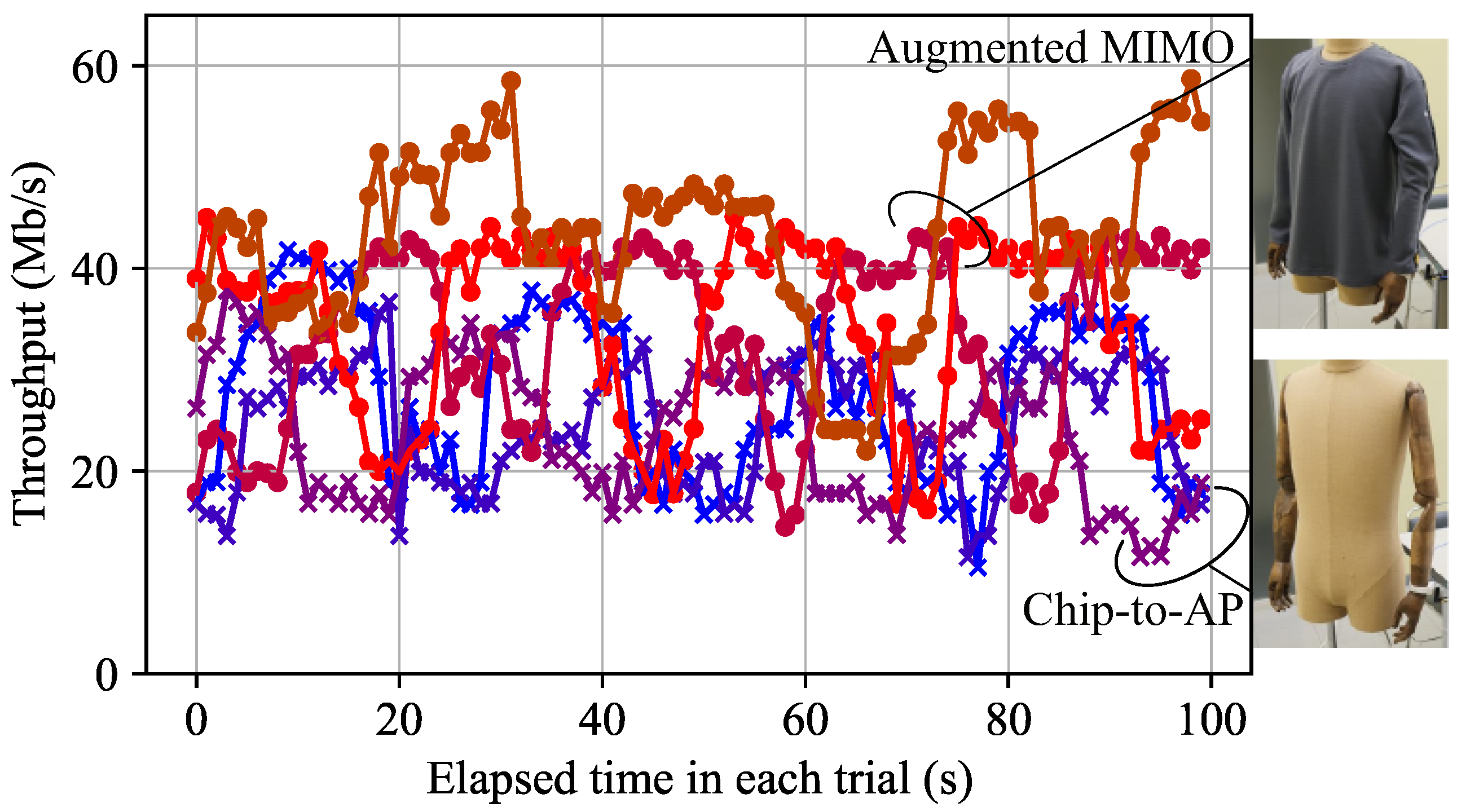
In the NLOS experiment, Augmented MIMO also improved throughput, but the ratio of its throughput to that of the chip-to-AP link dropped to 1.5. The SNR in the NLOS experiment is considered to be lower than that in the LOS experiment due to the blocked direct path and the longer distance between the transmitter and receiver.
The conditions for Augmented MIMO to improve the channel capacity need further investigation, and the limitations of Augmented MIMO should be clarified in future work.

6.2. Mutual Coupling in Original Antenna Array

The mutual coupling M chip in Figure 11, i.e., | S 21 | in Figure 2, is one of the dominant factors determining W. If M chip approaches 0 dB, it means that a chip antenna is transferring the signal to the other chip antenna rather than radiating it to the air; thus, it is virtually a single-antenna transceiver. This is interpreted as rank ( W ) = 1 . In this case, Augmented MIMO cannot contribute to increasing the channel capacity.
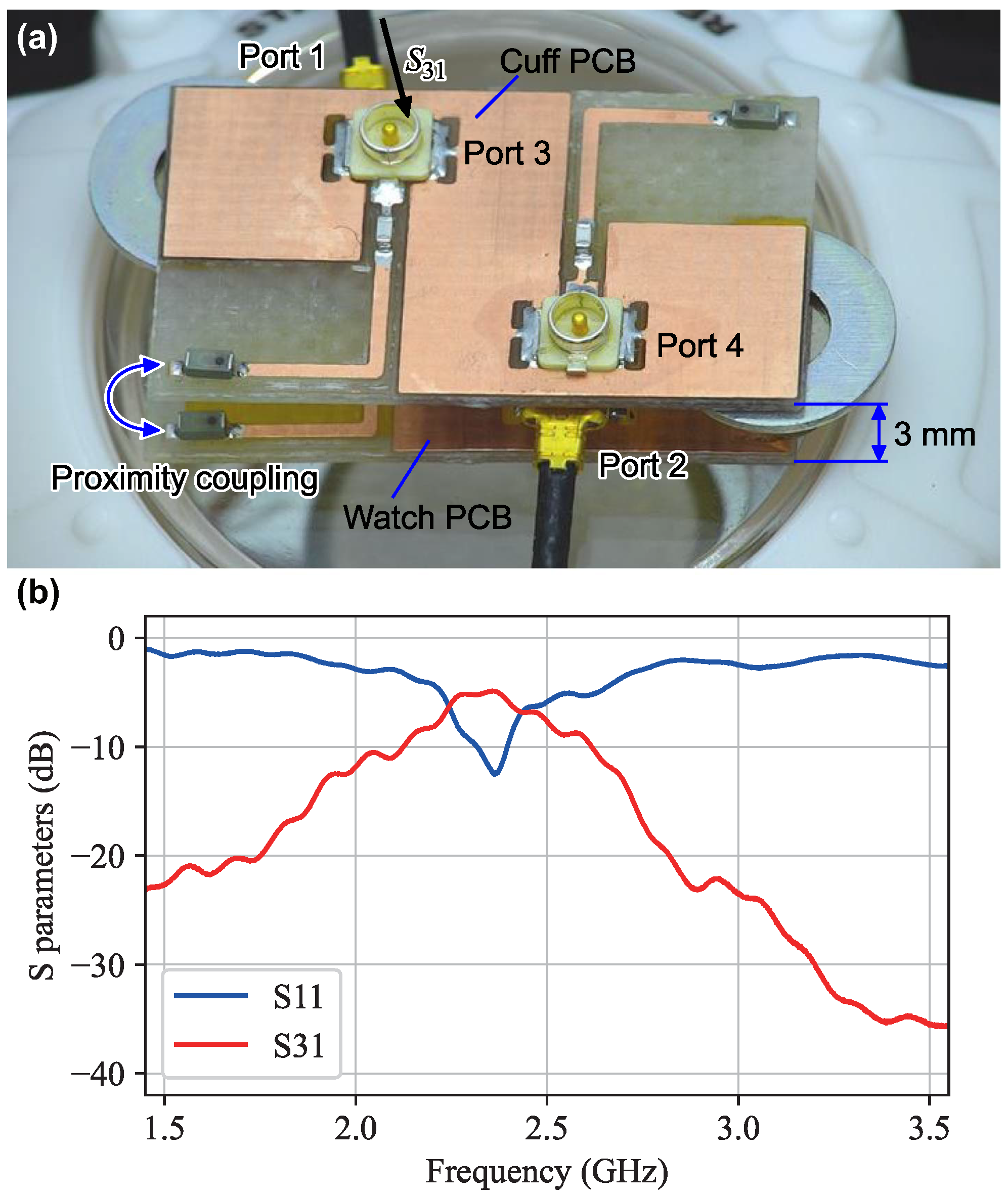
In our experiment, the mutual coupling M chip was about 14 dB, and the proximity coupling ( L prox ) was about 6.8 dB. The condition L prox > M chip means that the signal fed to one of the watch antennas is transferred more to the proximity-coupled cuff antennas than to the other watch antenna. This may have had a positive impact on the throughput improvement with Augmented MIMO.
Acceptable conditions for L prox and M chip should be further investigated in future work. In addition, as we have seen in 
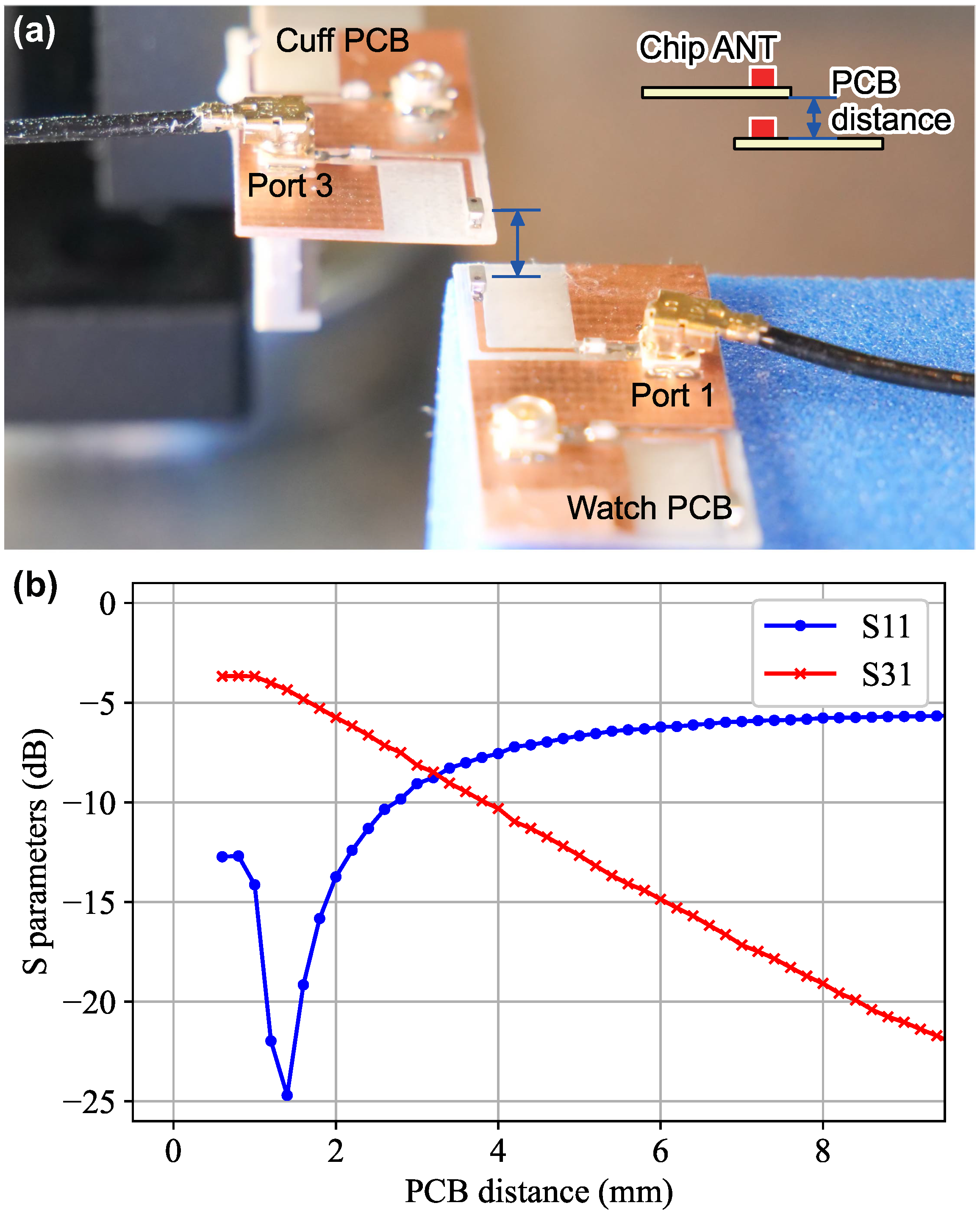
Figure 6, the proximity coupling can also be further increased by design optimization.

6.3. Cuff Antennas Influencing the Characteristics of Original Chip Antenna

Comparing Figure 2b and Figure 5b, we can see the influence of the proximity coupling of the cuff antenna array on the watch antenna characteristics. The resonant frequency is slightly lowered, and the minimum value of | S 11 | is reduced. It may also have influenced the antenna radiation patterns as reported in the literature [2], although we did not evaluate this.
Intuitively, the characteristic changing effects will be more significant with stronger proximity coupling. To increase the overall antenna gain G augmented in (3), the proximity coupling loss L prox should be reduced, which requires stronger coupling. However, stronger coupling changes the | S 11 | frequency characteristics; therefore, the return loss may increase. In our design, | S 11 | increased when the spacing was less than 1 mm, as shown in Figure 6, although | S 31 | did not decrease. The increase in | S 11 | can generally lead to an increase in L prox .
This trade-off should be addressed in future work.

6.4. Practical Textile-Based Implementation

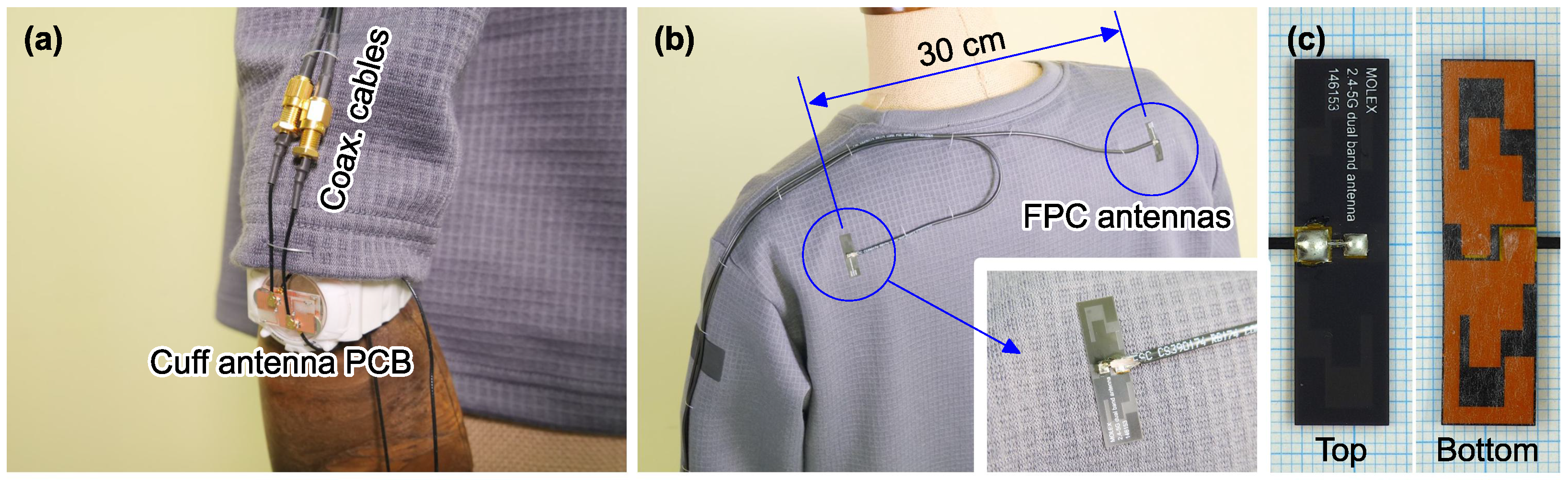
The Augmented MIMO clothing was prototyped using a commercially available 2.8 mm thick coaxial cable with acceptable flexibility for application in clothing. However, considering more realistic use cases where cables are frequently bent, twisted, and stretched, the durability of the cable is a critical issue. In addition, washability is another important factor for daily use.
From this point of view, the implementation of the system by integrating textile-based signal transmission media into a flexible textile, but not by cables attached outside the clothing, will be explored in future work. Related works found in the literature include coaxial cables [20], microstriplines [21], metamaterial transmission lines [22], and 2-D waveguides [23]. The integration of commercially available ultra-thin coaxial cables into flexible textiles is also an option, as such an implementation with machine washability has been reported [24]. In particular, the development of practical structures that achieve lower losses L cable with higher flexibility and durability will be of great interest. The magnitude of loss that can be acceptable is also an essential issue, and is related to the discussion in Section 6.1.

6.5. On-Body Antenna Locations and Isolation from Body

In the experiment, the FPC antennas were located at the shoulders. This antenna location is reasonable to avoid the shadowing effect by the user’s body itself and other furniture, assuming the access point is to be installed at a high position, such as near the ceiling, in daily indoor use cases. From this point of view, it is preferable to place the antenna close to the head.
On the other hand, for safety reasons, it is preferable to avoid RF radiation around the head [25]. In terms of the actual power radiated from the antennas, the antenna system implemented in clothing is completely passive and lossy; therefore, the power radiated from the shoulder antennas is less than that of the original watch antenna. However, safety, especially the user’s sense of security, depends not only on the absolute power but also on the factor of how close the radiating element is to the head. With regard to this factor, the Augmented MIMO scheme has a degree of freedom to choose antenna locations preferred by the users.
Thus, the appropriate antenna location on the clothing depends on the application and the user and is controversial; therefore, future research on this aspect is required; for example, psychophysical experiments with a large number of subjects.
Even for antennas away from the head, the backward radiation to the human body, causing safety issues and the degradation of antenna efficiency, is a common problem for wearable antennas. Reducing these unwanted effects by metamaterials is a promising approach [26], and extensive future research is expected.

7. Conclusions

In this paper, the concept of Augmented MIMO was proposed, and its effectiveness was empirically demonstrated. The experimental results demonstrate the throughput improvement with the proposed scheme, even if the overall antenna gain decreases with the external body-mounted antennas. The experimental results prove the existence of scenarios wherein the Augmented MIMO increases the channel capacity; however, its effectiveness depends on several factors, as discussed above.
The advantages of the proposed scheme include the following: (1) a significant improvement in MIMO performance due to high diversity gain; (2) a high degree of freedom in antenna placement; and (3) room for increasing the number of antennas toward massive MIMO. However, the proposed scheme features various issues that do not arise in conventional MIMO systems, such as the following: (1) the stability of proximity coupling between wearable devices and clothing; (2) the comfort of users wearing the antenna-distributed clothing; and (3) the durability of the clothing. Further detailed investigations that include theoretical aspects and practical system integration methods are needed to overcome these issues.
The proposed scheme can also be applied to multiband/wideband MIMO systems, although the experiment was designed for single-band operation for simplicity. This work contributes to the future development of yet another scheme to improve the communication performance of small wearable devices by using the human body as a spacious antenna fixture.

Funding

This research was supported in part by the JSPS Grant-in-Aid for Scientific Research (21H05301) and the Murata Science and Education Foundation.

Institutional Review Board Statement

Not applicable.

Informed Consent Statement

Not applicable.

Data Availability Statement

The original contributions presented in the study are included in the article; further inquiries can be directed to the corresponding author.

Conflicts of Interest

The author declares no conflicts of interest.

References

  1. Foschini, G.J. Layered space-time architecture for wireless communication in a fading environment when using multi-element antennas. Bell Labs Tech. J. 1996, 1, 41–59. [Google Scholar] [CrossRef]
  2. Chen, X.; Zhang, S.; Li, Q. A review of mutual coupling in MIMO systems. IEEE Access 2018, 6, 24706–24719. [Google Scholar] [CrossRef]
  3. Chen, W.S.; Yang, C.K.; Sin, W.S. MIMO antenna with Wi-Fi and Blue-Tooth for smart watch applications. In Proceedings of the 2015 IEEE MTT-S 2015 International Microwave Workshop Series on RF and Wireless Technologies for Biomedical and Healthcare Applications (IMWS-BIO), Taipei, Taiwan, 21–23 September 2015; pp. 212–213. [Google Scholar]
  4. Nadeem, I.; Choi, D.Y. Study on mutual coupling reduction technique for MIMO antennas. IEEE Access 2018, 7, 563–586. [Google Scholar] [CrossRef]
  5. Masouros, C.; Sellathurai, M.; Ratnarajah, T. Large-scale MIMO transmitters in fixed physical spaces: The effect of transmit correlation and mutual coupling. IEEE Trans. Commun. 2013, 61, 2794–2804. [Google Scholar] [CrossRef]
  6. Chataut, R.; Akl, R. Massive MIMO systems for 5G and beyond networks—overview, recent trends, challenges, and future research direction. Sensors 2020, 20, 2753. [Google Scholar] [CrossRef] [PubMed]
  7. Shah, S.M.A.; Zada, M.; Nasir, J.; Owais, O.; Iqbal, A.; Yoo, H. Miniaturized four-port MIMO implantable antenna for high-data-rate wireless-capsule-endoscopy applications. IEEE Trans. Antennas Propag. 2023, 71, 3123–3133. [Google Scholar] [CrossRef]
  8. Karim, R.; Iftikhar, A.; Ijaz, B.; Mabrouk, I.B. The potentials, challenges, and future directions of on-chip-antennas for emerging wireless applications—A comprehensive survey. IEEE Access 2019, 7, 173897–173934. [Google Scholar] [CrossRef]
  9. Li, Z.; Du, Z.; Takahashi, M.; Saito, K.; Ito, K. Reducing mutual coupling of MIMO antennas with parasitic elements for mobile terminals. IEEE Trans. Antennas Propag. 2011, 60, 473–481. [Google Scholar] [CrossRef]
  10. Wen, D.; Hao, Y.; Wang, H.; Zhou, H. Design of a MIMO antenna with high isolation for smartwatch applications using the theory of characteristic modes. IEEE Trans. Antennas Propag. 2018, 67, 1437–1447. [Google Scholar] [CrossRef]
  11. Fan, Y.; Huang, J.; Chang, T.; Liu, X. A miniaturized four-element MIMO antenna with EBG for implantable medical devices. IEEE J. Electromagn. RF Microwaves Med. Biol. 2018, 2, 226–233. [Google Scholar] [CrossRef]
  12. Esmail, B.A.; Koziel, S. Design and optimization of metamaterial-based highly-isolated MIMO antenna with high gain and beam tilting ability for 5G millimeter wave applications. Sci. Rep. 2024, 14, 3203. [Google Scholar] [CrossRef] [PubMed]
  13. Almers, P.; Tufvesson, F.; Molisch, A.F. Keyhole effect in MIMO wireless channels: Measurements and theory. IEEE Trans. Wirel. Commun. 2006, 5, 3596–3604. [Google Scholar] [CrossRef]
  14. TSA5N18D2G45NV001T|Chip Antennas|Taiyo Yuden Co., Ltd. Available online: https://ds.yuden.co.jp/TYCOMPAS/ut/detail?pn=TSA5N18D2G45NV001T (accessed on 15 December 2024).
  15. U.FL Series—HIROSE Electric Group [Connector]. Available online: https://www.hirose.com/en/product/series/U.FL (accessed on 15 December 2024).
  16. Hallbjorner, P. The significance of radiation efficiencies when using S-parameters to calculate the received signal correlation from two antennas. IEEE Antennas Wirel. Propag. Lett. 2005, 4, 97–99. [Google Scholar] [CrossRef]
  17. Antennas Part 1461530050|Molex. Available online: https://www.molex.com/en-us/products/part-detail/1461530050 (accessed on 15 December 2024).
  18. iPerf2—A Means to Measure Network Responsiveness and Throughput. Available online: https://sourceforge.net/projects/iperf2/ (accessed on 15 December 2024).
  19. Adeleke, O.A.; Bastin, N.; Gurkan, D. Network traffic generation: A survey and methodology. ACM Comput. Surv. (CSUR) 2022, 55, 1–23. [Google Scholar] [CrossRef]
  20. Joshi, R.; Podilchak, S.K.; Constantinides, C.; Low, B. Flexible Textile-Based Coaxial Transmission Lines for Wearable Applications. IEEE J. Microwaves 2023, 3, 665–675. [Google Scholar] [CrossRef]
  21. Januszkiewicz, Ł.; Nowak, I. Knitted Microwave Transmission Line for Wearable Electronics. Appl. Sci. 2024, 14, 10798. [Google Scholar] [CrossRef]
  22. Tian, X.; Lee, P.M.; Tan, Y.J.; Wu, T.L.; Yao, H.; Zhang, M.; Li, Z.; Ng, K.A.; Tee, B.C.; Ho, J.S. Wireless body sensor networks based on metamaterial textiles. Nat. Electron. 2019, 2, 243–251. [Google Scholar] [CrossRef]
  23. Noda, A.; Shinoda, H. Inter-IC for Wearables (I2We): Power and data transfer over double-sided conductive textile. IEEE Trans. Biomed. Circuits Syst. 2018, 13, 80–90. [Google Scholar] [CrossRef] [PubMed]
  24. Zhu, X.; Wu, K.; Xie, X.; Anderson, S.W.; Zhang, X. A robust near-field body area network based on coaxially-shielded textile metamaterial. Nat. Commun. 2024, 15, 6589. [Google Scholar] [CrossRef]
  25. International Commission on Non-Ionizing Radiation Protection and Others. Guidelines for limiting exposure to time-varying electric, magnetic, and electromagnetic fields (up to 300 GHz). Health Phys. 1998, 74, 494–522. [Google Scholar]
  26. Ali, U.; Ullah, S.; Kamal, B.; Matekovits, L.; Altaf, A. Design, analysis and applications of wearable antennas: A review. IEEE Access 2023, 11, 14458–14486. [Google Scholar] [CrossRef]
Figure 1. (a) A MIMO link between an AP and a smartwatch. Two small chip antennas (ANTs) are embedded in the smartwatch with a spacing significantly smaller than the wavelength. (b) Augmented MIMO link. Chip antennas in the smartwatch are proximity-coupled to the other two antennas attached around the cuff of the clothing. The two cuff antennas are individually connected to two shoulder-mounted flexible antennas with coaxial cables. The shoulder antennas are nearly half a wavelength in size and more than a wavelength apart.
Applsci 15 00557 g001
Figure 2. (a) The two-element chip antenna array PCB. The background is 1 mm grid paper. (b) The easured S parameters. Around the 2.4 GHz band, the reflection | S 11 | decreases to about 7 dB. Due to mutual coupling between the two antennas, the isolation between ports 1 and 2 is degraded to | S 21 |     14 dB.
Applsci 15 00557 g002
Figure 3. The MIMO antenna array on a watch for the experiment. Two magnets are bonded on the PCB to align and fix the clothing-cuff antenna PCB.
Applsci 15 00557 g003
Figure 4. (a) An antenna array PCB identical to the watch PCB is attached to the cuff of the clothing. A close-up view of the stacked pair of the cuff antenna PCB and the watch antenna PCB is shown in Figure 5a. (b) Two FPC antennas are attached to the shoulders. The cuff antennas and shoulder antennas are connected with flexible coaxial cables. (c) A close-up photograph of the 35 mm × 9 mm FPC antenna. The background is 1 mm grid paper. Its conductive pattern is clearly visible in the bottom view.
Applsci 15 00557 g004
Figure 5. (a) Two identical antenna PCBs, the cuff PCB and the watch PCB, are aligned and fixed by the magnet fixtures. (b) The measured S parameters. The transmittance from the watch PCB antenna to the proximity-coupled antenna, | S 31 | , is about −7 dB at the 2.4 GHz band.
Applsci 15 00557 g005
Figure 6. (a) Setup to measure transmittance dependence on PCB distance. One of the PCBs is rotated to avoid the mechanical interference of coaxial connectors. The minimum PCB distance is 0.6 mm, due to the height of the chip antenna. (b) Measured | S 11 | and | S 31 | at 2.45 GHz.
Applsci 15 00557 g006
Figure 7. (a) A schematic diagram of experimental system for measuring the throughput of Augmented MIMO. (b) An overview of the experimental system of chip-to-AP link. (c) The watch antennas are connected to the external antenna ports of a WLAN dongle on the IPerf client PC. (d) An overview of Augmented MIMO evaluation system. (e) In the Augmented MIMO system, the cuff antenna PCB is stacked onto the watch PCB.
Applsci 15 00557 g007
Figure 8. Throughput measurement in an NLOS environment with many scattered objects, such as stools placed on desks. The WLAN router is placed behind the whiteboard and is 8.8 m distant from the client.
Applsci 15 00557 g008
Figure 9. The throughput evaluation results, including three trials each for the chip-to-AP link (plotted with “×” markers) and Augmented MIMO link (“∘” markers). Different colored lines indicate different trials. Augmented MIMO was, on average, more than twice as fast as the chip-to-AP link.
Applsci 15 00557 g009
Figure 10. Throughput evaluation results for the NLOS environment. Different colored lines indicate different trials. Augmented MIMO (“∘” markers) was, on average, 1.5 times faster than the chip-to-AP link (“×” markers).
Applsci 15 00557 g010
Figure 11. Antenna gains and losses in peripheral components in (a) chip-to-AP and (b) Augmented MIMO links.
Applsci 15 00557 g011
Disclaimer/Publisher’s Note: The statements, opinions and data contained in all publications are solely those of the individual author(s) and contributor(s) and not of MDPI and/or the editor(s). MDPI and/or the editor(s) disclaim responsibility for any injury to people or property resulting from any ideas, methods, instructions or products referred to in the content.

