1. Introduction
In research, the most important thing is to have a good and productive idea. One way for new ideas to arise is through theoretical considerations, while another way is through practical experience obtained during the development and implementation of new products. The latter is more typical for applied sciences. The idea of creating and developing feedback control systems for plants with asymmetric dynamics came from the development and implementation of frequency converters for the control of water and liquefied gas pump drives with induction AC motors. These fluid delivery systems are particularly characterized by asymmetric dynamics. The term asymmetric dynamics is understood to mean that the dynamics of the response of the controlled parameter of the plant to the rise and fall of the plant control signal are different. In other words, the transfer function of the controlled plant when the control signal increases does not coincide with the one it has when this signal decreases.
It is understandable that any actual controlled plant has absolutely symmetric dynamics. In most practical cases, the asymmetry of the dynamics is small and does not affect the quality of control; therefore, it is not necessary to assess it. However, if the asymmetry is significant, control algorithms adapted to plants with symmetric dynamics do not allow for achieving high control quality, and in the case of large asymmetry, the control system may become unstable. Strongly expressed asymmetry can be observed in plants where the controlled parameter value is increased and decreased by different mechanisms or means, as it happens in liquid supply systems. In these cases, the problem of asymmetry of dynamics becomes important. Despite the fact that the problem of control systems with asymmetric dynamics is relevant and is an attractive object for research, few scientific publications can be found on this issue [
1,
2,
3,
4,
5,
6,
7,
8].
This work is a continuation of works [
2,
5,
6,
8]. In works [
2,
5], the control systems were analyzed where the dynamic asymmetry is caused only by the asymmetry of the controlled plant’s time constant, and in works [
6,
8], only by the asymmetry of the response delay of the plant. The purpose of the current work is to analyze a more complex case, where the asymmetry is introduced by both dynamic parameters of the controlled plant: by the asymmetry of the time constant and by the asymmetry of the response delay. Such a case is more consistent with real plants characterized by dynamic asymmetry.
This work examines control systems in which the controlled plant has a response delay and is described by a first-order transfer function, i.e., systems with FOPDT (first order plus dead time) plants are analyzed. The FOPDT transfer function is used to present many real controlled plants (processes) [
9,
10,
11,
12,
13,
14,
15,
16,
17]. For an FOPDT plant with asymmetric dynamics caused by the changes in the response delay and the time constant, the transfer function can be described by the following expressions:
where
Gp (
s) is the transfer function of the plant;
t is time;
Tr is the response delay of the plant that acts when the plant responds to a rising control signal
Up(
t);
Tf is the response delay that operates when the plant responds to a falling control signal;
τr is the time constant of the plant operating when controlled plant parameter
Ya(
t) rises; and
τf is the time constant that acts when the controlled parameter of the plant falls.
The controlled plant is characterized by a delay in response Tr when it responds to the rising control signal Up(t). At that time, the controlled parameter Ya(t) can not only increase but also decrease; therefore, in the latter case, the controlled plant will be described by a transfer function in which T = Tr, τ = τf. A similar situation can be observed when the value of Up(t) decreases. In this case, Ya(t) may not only decrease but can also increase. In other words, the specificity of a plant with asymmetric dynamics is that if the response delay is switched to the Tr value, the time constant will not necessarily be switched to the τr value. An analogous situation can occur when the response delay is switched to the Tf value.
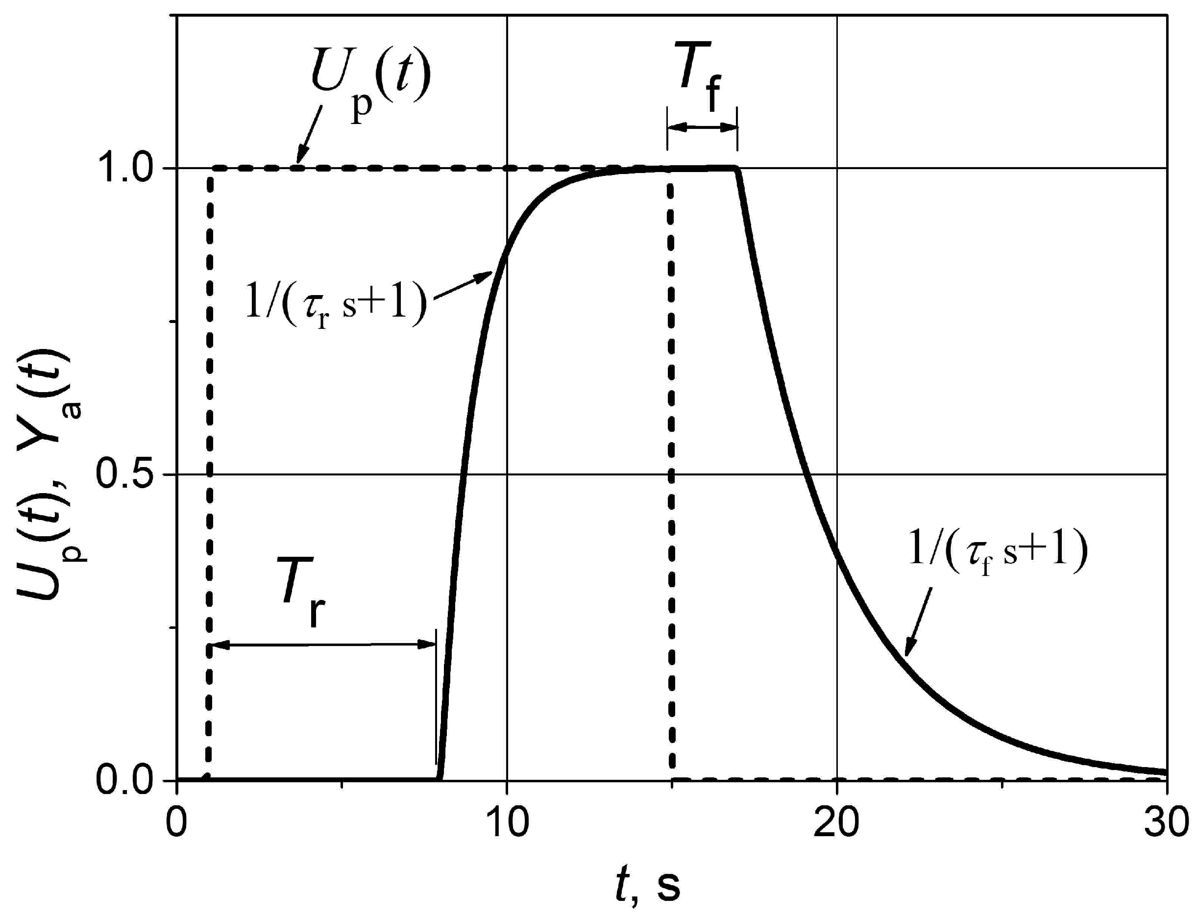
A peculiarity of the analysis of control systems with asymmetric dynamics in the time domain is that it is not enough to analyze the set point and load disturbance step responses, as in systems with symmetric dynamics. In the case of asymmetric dynamics, it is necessary to study the pulse response because the plant dynamics are different when the controlled parameter of the plant rises and falls. The response example of an FOPDT plant with asymmetric dynamics to a unit pulse is presented in
Figure 1. The
Ya(
t) in
Figure 1 is the controlled plant parameter.
The novelty of this work is that it considers the case of dynamic asymmetry when it is introduced by changes in both dynamic parameters of the controlled plant: the time constant and the response delay. Another novelty is that it is proposed to modify the asymmetric PI (aPI) controller with the switched parameters proposed in [
5,
6]. The essence of the improvement is to use the change in the sign of the time derivative of the plant’s control signal
Up(
t)/d
t as the criterion to fix the time moments at which the controller parameters have to be switched. Meanwhile, in works [
5,
6], the change in the sign of the control error
e(
t) is used to fix these time moments, and because of this, the aPI controller parameters are not always switched in time.
The structure of the paper is as follows:
Section 1 reviews the research problem and describes the purpose of the work and the novelty of the results obtained;
Section 2 presents the proposed asymmetric proportional-integral (aPI) control algorithm and its mathematical model in the Matlab/Simulink environment; the FOPDT plants with asymmetric dynamics under study are also described in this section;
Section 3 presents the investigation results of the analyzed control systems with asymmetric dynamics plants based on the aPI and conventional PI controllers; the results of the work and areas for their application are discussed in
Section 4; and the conclusions of the work are presented in
Section 5.
2. Materials and Methods
In practical applications, feedback control systems are usually implemented using PI and PID controllers [
18,
19,
20,
21,
22,
23,
24,
25,
26,
27,
28,
29]. Therefore, from a practical point of view, it would be appropriate to modify PI and PID controllers, adapting them to the control of plants with asymmetric dynamics. This would be suitable because engineers who install and operate automatic control systems are well aware of these controllers and know how to tune their parameters to the dynamics of the controlled plant.
For the control of the studied FOPDT plants with asymmetric dynamics, an asymmetric PI (aPI) controller, which is similar but not the same as that described in [
5,
6], has been used. The parameters of the aPI controller are variable, i.e., their values are discretely changed when the dynamic parameters of the controlled plant change. The main problem when using the aPI controller is to correctly determine the time points when the controller parameters should be switched. In the aPI controller presented in [
5,
6], the controller parameters are switched when the sign of the control error
e(
t) changes. Such a criterion can be used since the control error
e(
t) =
Yd(
t) −
Ya(
t) is positive when the actual value of the controlled parameter
Ya(
t) is less than the desired value (set point)
Yd(
t). Because of this, the feedback controller, in order to reduce
e(
t), has to increase
Ya(
t) by increasing the plant control signal
Up(
t). If the error is negative, i.e.,
Ya(
t) >
Yd(
t), then in order to reduce the absolute value of
e(
t), the controller has to decrease
Ya(
t) by decreasing
Up(
t). From the explanation above, we see that the sign of
e(
t) correlates with the sign of the time derivative
Up(
t)/d
t. Therefore, the moment of change of the
e(
t) sign can be used to determine the moments of switching the controller parameters since the parameters have to be switched when the sign of the derivative
Up(
t)/d
t changes. The error
e(
t) is always measured in the control system, so no additional measures are required to determine its value, making such a controller easier to implement in practice.
However, the response of the controlled parameter of the FOPDT plant Ya(t) to the change in the control signal Up(t) is delayed, and therefore, the change in the control error e(t) is delayed. This means that the change in the sign of the e(t) may be delayed relative to the change in the sign of the Up(t)/dt. Meanwhile, the controller parameters must be switched when the Up(t)/dt sign changes, because at that moment, the parameters of the plant with asymmetric dynamics change. Therefore, higher control quality can be achieved when the controller parameters are switched using the Up(t)/dt sign criterion, although in this case, it is necessary to additionally measure the derivative Up(t)/dt.
In this work, the moment of change of the plant’s control signal time derivative
Up(
t)/d
t sign is used to determine the moments for the switching of controller parameters, and this is how it differs from the aPI controller proposed in previous work [
5,
6]. The algorithm of such a modified aPI controller is as follows:
where
U(
t) is the controller signal,
Kpr and
Kir are proportional and integral constants, respectively, when the time derivative of the plant control signal is positive or zero, and
Kpf and
Kif are proportional and integral constants, respectively, when the time derivative of the plant control signal is negative.
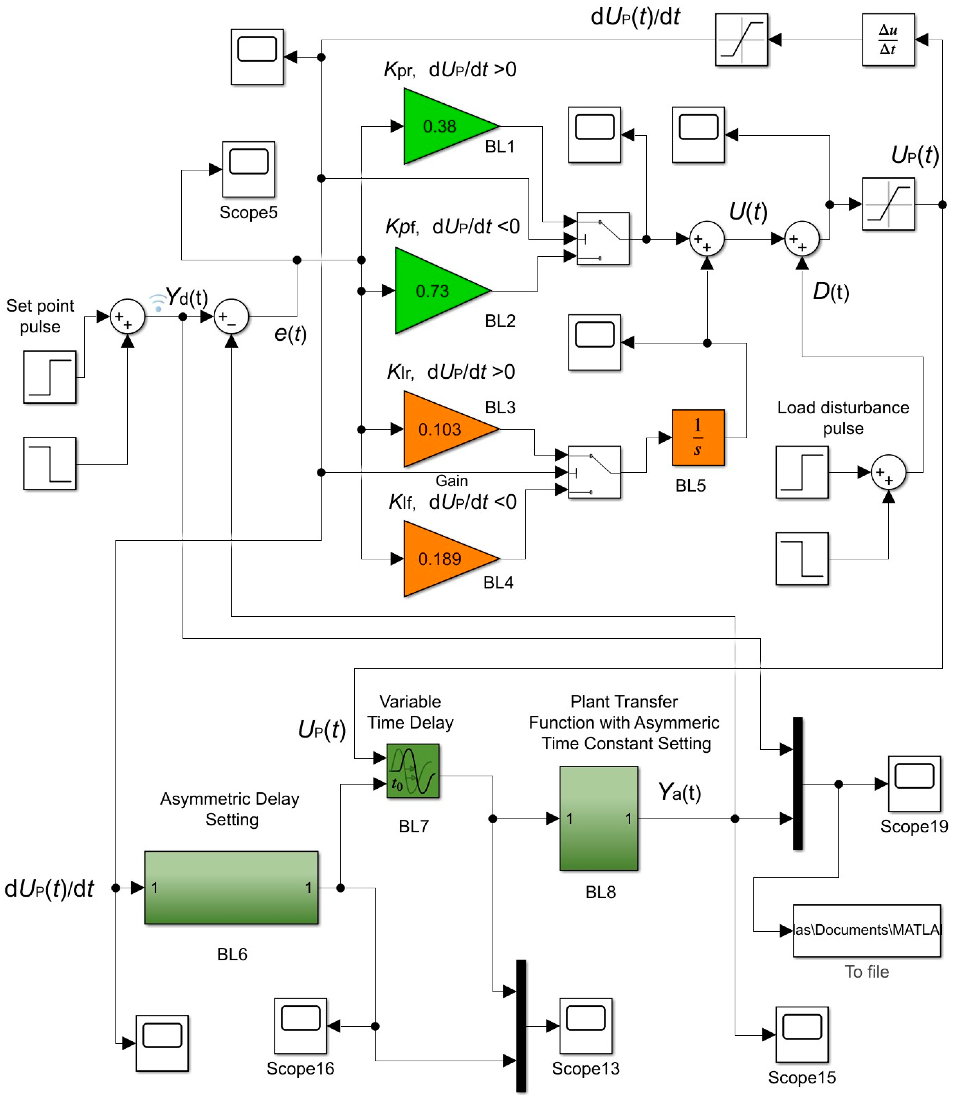
The analysis of feedback control systems of FOPDT plants with asymmetric dynamics was performed using the Matlab/Simulink program. The circuit diagram of the Matlab/Simulink model of the analyzed feedback control system based on the aPI controller (2) is presented in
Figure 2.
In
Figure 2,
Yd(
t) and
Ya(
t) are the set point value (desired value) and actual value of the controlled plant parameter, respectively, while
D(
t) is the load disturbance. Blocks BL1–BL5 form the aPI controller model, with the switched parameters described by Equation (2). Blocks BL6–BL8 present the controlled FOPDT plant with asymmetric dynamics described by the transfer function (1).
Blocks BL6 and BL7 implement a variable delay of the plant response. Asymmetric delay setting block BL6, depending on the sign of the time derivative of the plant’s control signal dUp(t)/dt, creates two discrete signal values for controlling the variable time delay block BL7. When the derivative is positive (dUp(t)/dt ≥ 0), block BL7, controlled by the signal of block BL6, switches the delay to the Tr value, when it is negative (dUp(t)/dt < 0) − to the Tf value. Therefore, the value of the delay of the plant’s response is switched when the time derivative dUp(t)/dt changes the sign. Block BL8 implements the transfer function of the plant with a switched time constant. When the controlled plant parameter Ya(t) increases (dYa(t)/dt ≥ 0), the time constant value τr is applied, and when it decreases (dYa(t)/dt < 0), the value τf is used.
Table 1 presents the parameters of the transfer functions of the four analyzed FOPDT plants with asymmetric dynamics (1). The operation of the control systems was studied using the proposed aPI controller (2), and the results obtained were also compared with the cases using a conventional PI controller.
Table 1 also presents the parameters of the aPI and PI controllers used in the simulation. The parameters of controllers were obtained through simulation using the automated PID controller tuning block of Matlab/Simulink software (version R2021b). It allows one to obtain parameter values to acquire the desired control system response transient. In this work, the controller parameters were tuned according to the criterion of the minimum settling time for the control system response to the unit set point pulse, when the overshoots do not exceed 5%.
When tuning an aPI controller in practice, it can be considered that there are two separate controllers, similar to in reference [
30]. One PI controller operates when the plant control signal rises, and the other when it falls. Therefore, the tuning of the parameters of the aPI controller is reduced to the process of tuning two separate conventional PI controllers with parameters
Kpr,
Kir, and
Kpf,
Kif. The PI controller with parameters
Kpr,
Kir is tuned to the desired rising control signal response of the control system, and the controller with parameters
Kpf,
Kif is tuned to the desired falling control signal response.
This work investigated the set point and load disturbance pulse responses of feedback control systems with asymmetric dynamics. The robustness of control systems was also analyzed. The investigation of control systems was carried out according to the following plan: first, the control of asymmetric dynamic plants using a conventional PI controller was analyzed; then, the same control systems were studied, but using the aPI controller, and then a robustness analysis of control systems with the aPI controller was performed.
3. Results
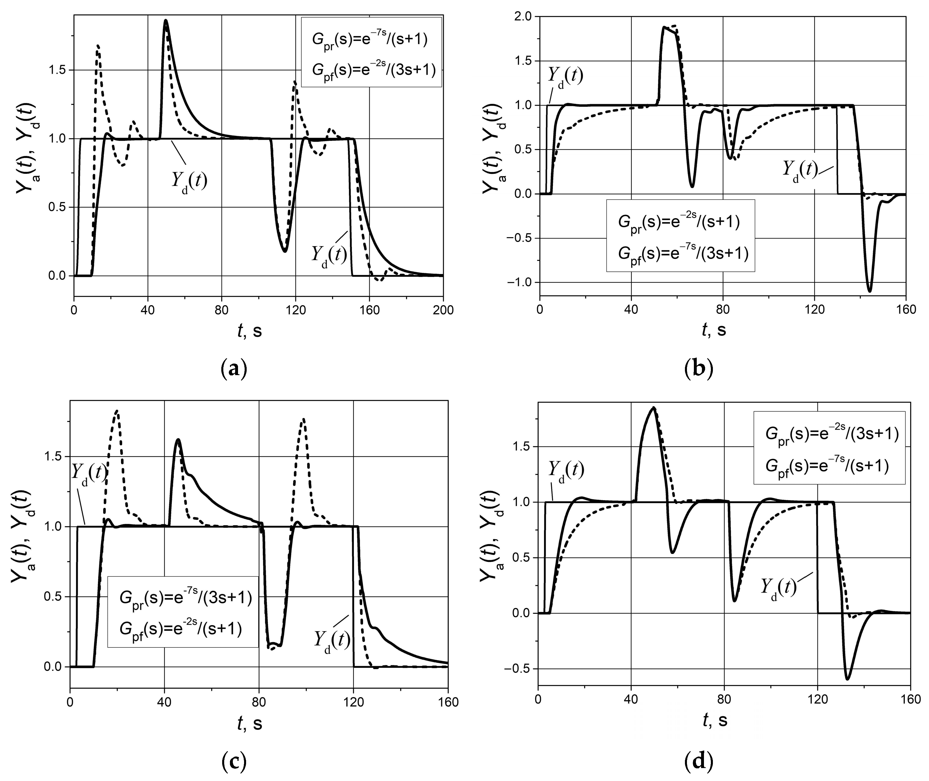
The set point
Yd(
t) unit pulse and unit (positive and negative) load disturbance
D(
t) responses of the control systems of the FOPDT plants with asymmetric dynamics, with the parameters given in
Table 1 based on the conventional PI controller, are presented in
Figure 3. The conventional PI controller is designed for plants with symmetric dynamics, and its parameters can only be adjusted for the case when the controlled parameter of the plant with asymmetric dynamics
Ya(
t) rises or when it falls.
Figure 3 shows the responses for both cases. We can see that if the controller parameters are tuned to the dynamics of the plant that has the
Ya(
t) rising (solid lines), then during the falling of the
Ya(
t), the response is slow (
Figure 3a,c) or the response has an unacceptably large overshoot (
Figure 3b,d). The same is true for the case where the PI controller parameters are tuned to the dynamics of the plant that has the
Ya(
t) falling (dashed lines). The parameters of the PI controller were the same as the parameters of the aPI controller given in
Table 1. When the PI controller was adjusted for a rising dynamics of
Ya(
t), the parameters
Kpr and
Kir were used, while for falling dynamics, the parameters
Kpf and
Kif were applied.
Based on the obtained results (
Figure 3), it can be stated that a conventional PI controller does not allow for achieving good control quality when controlling plants with strongly expressed dynamic asymmetry.
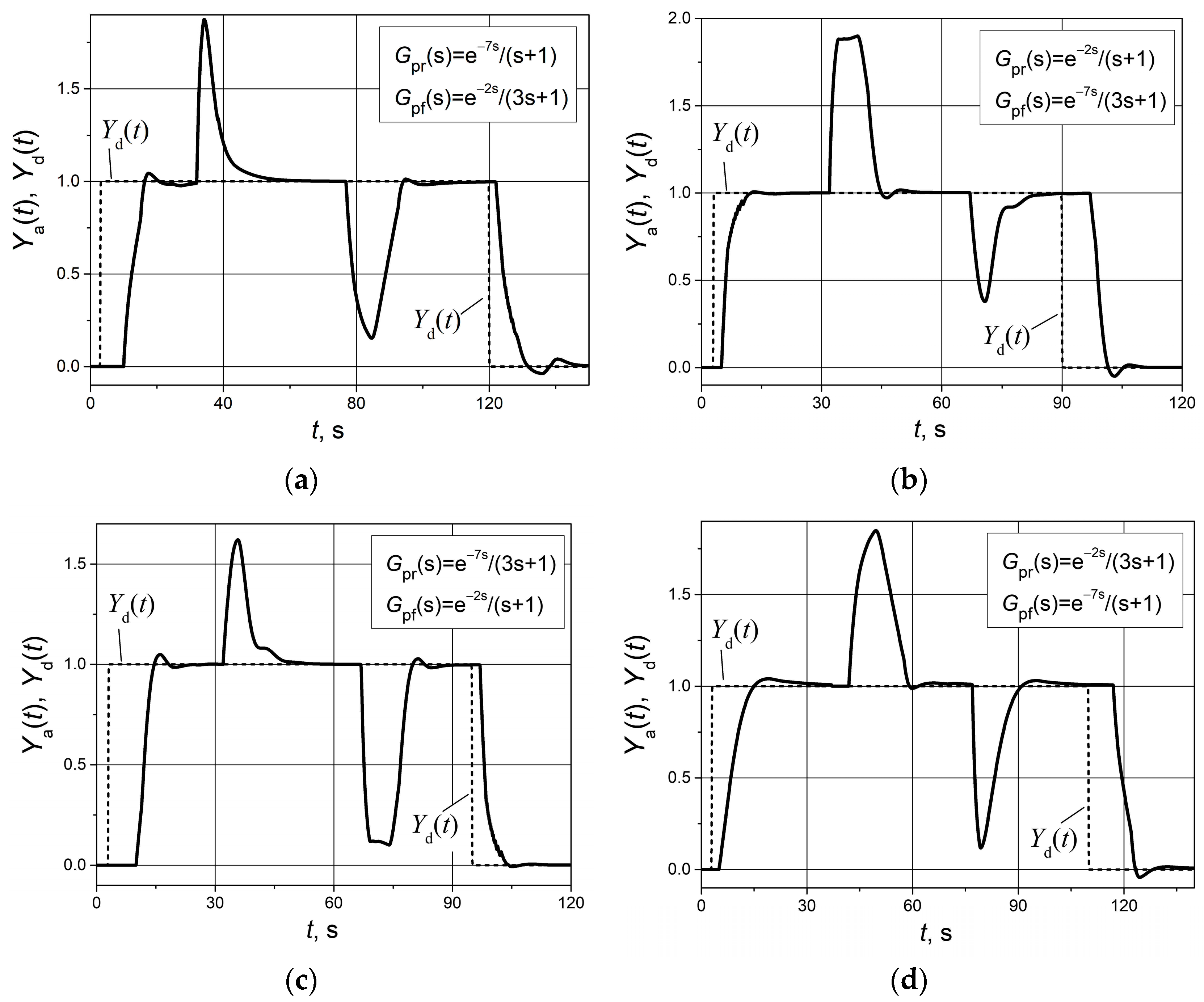
In practice, when controlling asymmetric dynamic plants, efforts are made to select some average parameter values for a conventional PI controller in order to obtain a compromise solution. In this case, there is no very large overshoot during the response to one edge of the set point pulse, and the response during the other edge of the set point pulse is not very slow.
Figure 4 presents the simulation results when the average values were selected for the PI controller to obtain acceptable dynamics during the rising and falling of the controlled plant parameter
Ya(
t). The arithmetic averages of the parameters given in
Table 1 were used. They were calculated as follows: K
p = (
Kpr +
Kpf)/2, K
i = (
Kir +
Kif)/2.
It can be seen that in this case, overshoots of
Ya(
t) are lower during the response to one edge of the set point pulse and the response is faster during the other edge (compare the graphs in
Figure 4 with the corresponding graphs in
Figure 3). However, the response of
Ya(
t) to neither edge of the set point pulse is of high quality in such a case.
Figure 5 presents the unit pulse set point and unit positive and negative load disturbance responses of feedback control systems with the aPI controller (2) and asymmetric dynamics plants whose transfer function parameters are given in
Table 1. The aPI controller parameter values are presented in
Table 1 as well.
The obtained transient curves (
Figure 5) show that the response of control systems using the aPI controller is of high quality, with a short settling time and an overshoot not exceeding 5%. This allows us to state that the use of an aPI controller (2) instead of a conventional PI controller allows us to improve the quality of control of plants with asymmetric dynamics. It is also important that the problem is solved using a PI-type controller, as automation engineers are well aware of them and know how to tune the parameters to the dynamics of the plant. Therefore, the aPI controller is attractive in practical applications.
The quantitative performance indices of the analyzed asymmetric dynamics control systems based on aPI and PI controllers are presented in
Table 2. The following are provided: settling time at 5% error band; overshoot; integral of absolute error (IAE); and integral of squared error (ISE). The indices were obtained based on the transients presented in
Figure 4 and
Figure 5, i.e., for the case when PI controller parameters are adjusted for average values.
The obtained indices show that the application of an aPI controller instead of a PI allows us to reduce the settling time of the control system by up to 2.5 times and overshoot by up to 11 times. The obtained IAE and ISE indices in all cases are lower in control systems with an aPI controller.
In practice, the dynamic parameters of controlled plants are often not constant, i.e., their values may change as the control system’s operating conditions change. Meanwhile, it is very important that the operation of the control system remains stable when the parameters of the plant change. The ability of a feedback control system to operate stably when the plant parameters change is called robustness.
The studied FOPDT plants have two dynamic parameters: the response delay and the time constant. Since these are plants with asymmetric dynamics, they have two different values of these parameters (
Table 1). We analyzed how the deviation of these parameters from the nominal value affects the operation of the control system when the parameters of the aPI controller are adjusted to the nominal values of the parameters of the plants.
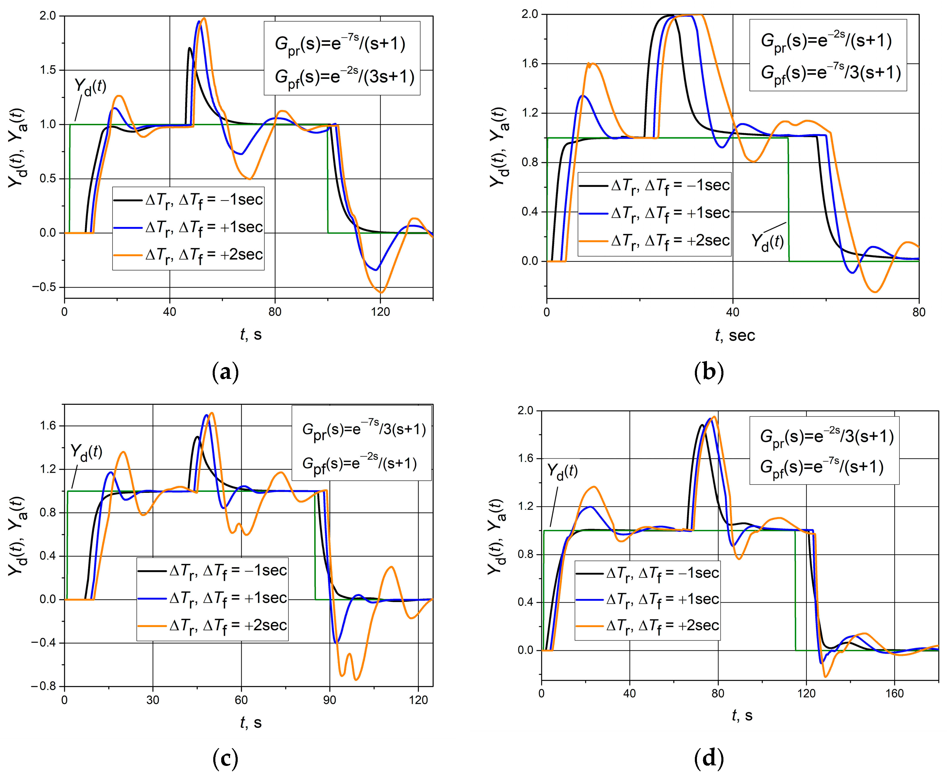
Cases were studied where both response delay (
Tr and
Tf) values changed by the same value Δ
Tr = Δ
Tf while the time constants
τr and
τf remained unchanged and were equal to the nominal values. The response of the control system to a unit set point pulse and to a positive unit load disturbance step was studied. The results of the analysis are presented in
Figure 6. We see that in the case where the plant response delays decrease, the response quality remains good—without any overshoot, only the settling time increases slightly (compare the transients presented in
Figure 6 with the corresponding transients presented in
Figure 5). However, when the response delays increase relative to the nominal values, a large overshoot appears in the control system response, and the settling time increases significantly. Despite this, the operation of the control systems with the studied asymmetric dynamics plants remained stable even at the studied maximum increases in the response delay time Δ
Tr = Δ
Tf = 2 s.
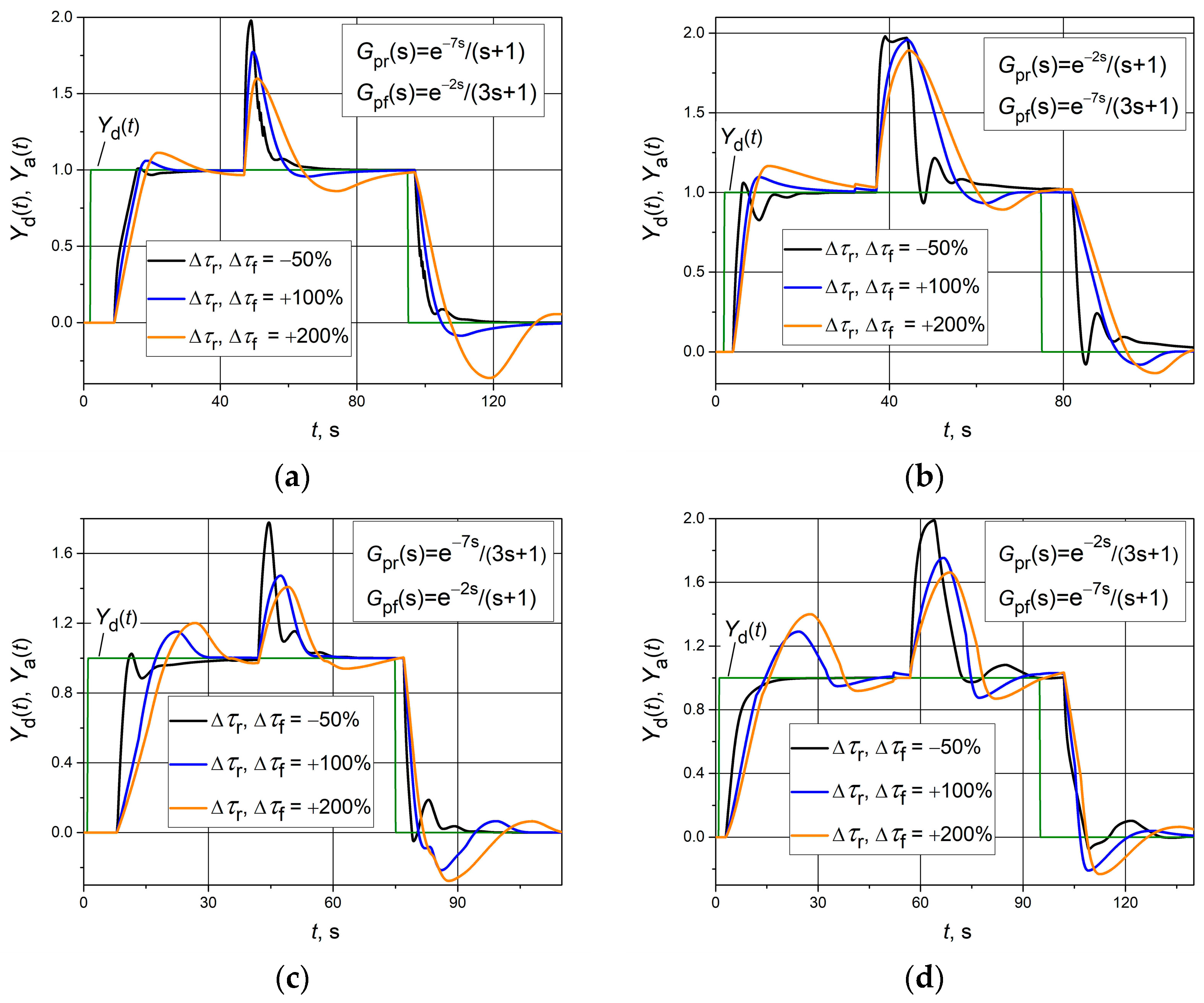
In another investigation, transients were obtained when time constants (
τr and
τf) changed by the same value Δ
τr = Δ
τf, while the response delays
Tr and
Tf remained unchanged and were equal to the nominal values. The response of the control system to a unit set point pulse and to a positive unit load disturbance step was analyzed. The results of the analysis are presented in
Figure 7. We see that in the case where the plant time constants decrease, the response quality of plants 1 (
Figure 7a) and 4 (
Figure 7d) remains quite good, with low overshoots and only the settling time increasing slightly (compare the transients presented in
Figure 7a,d with the corresponding transients presented in
Figure 5). When the time constants increase relative to the nominal values, a large overshoot appears in the control system response, and the settling time increases significantly. However, the operation of the control systems with the studied asymmetric dynamics plants remained stable even at the analyzed maximum increases in the time constants Δ
τr = Δ
τf = +200%.
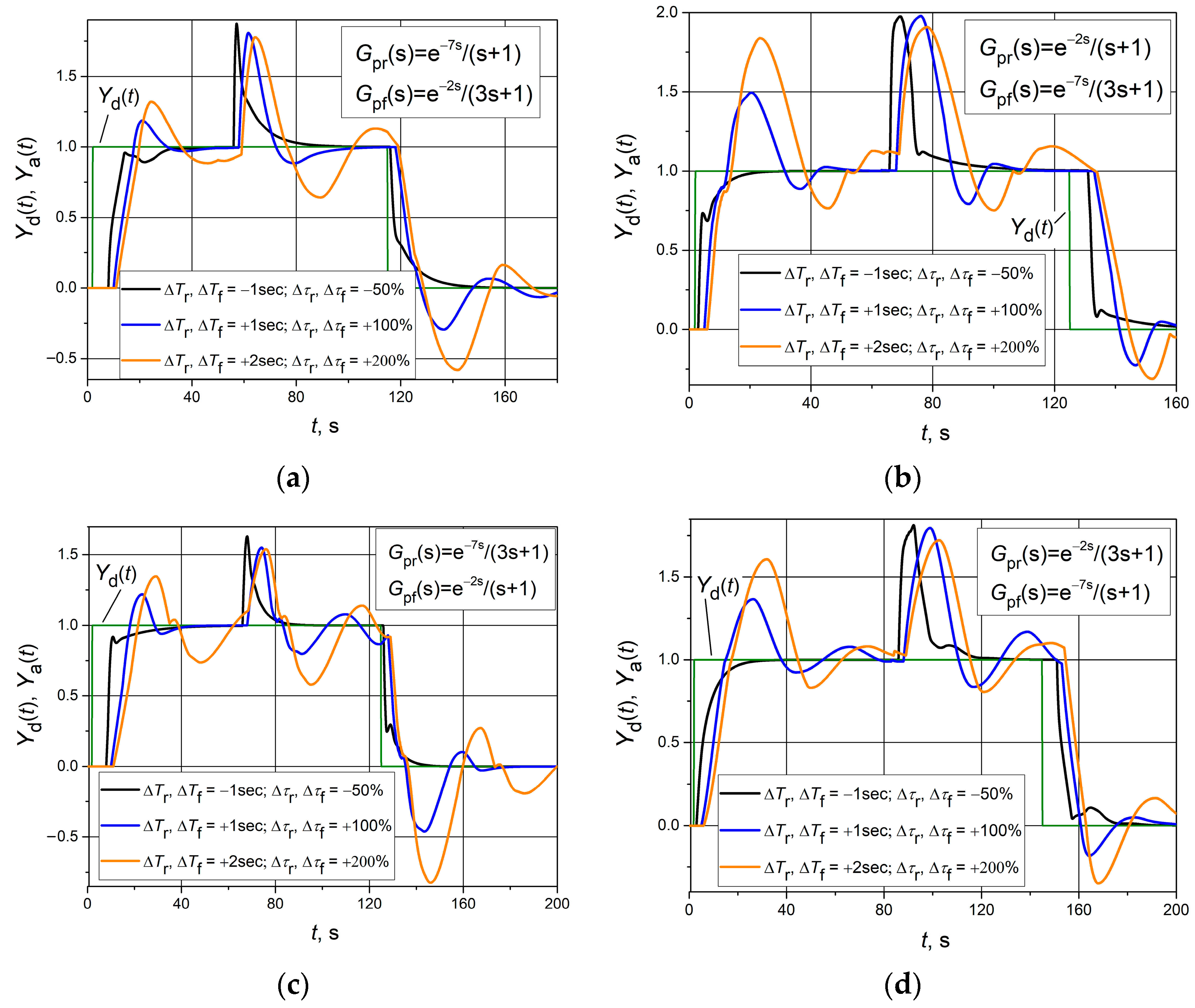
Finally, cases where both parameters of the plants—response delay and time constant—change in values Δ
Tr = Δ
Tf and Δ
τr = Δ
τf, respectively, were investigated. In this case, the operation of the control systems is most affected because both plant parameters change. As in previous cases, the response of the control system to a unit set point pulse and to a positive unit load disturbance step was analyzed. The resulting transients are presented in
Figure 8.
Compared to the results of studies that examined cases in which only the effects of the response delay (
Figure 6) or time constant (
Figure 7) change were analyzed, the results obtained show (
Figure 8) that as both of the aforementioned plant parameters increase relative to nominal values, overshoots and response settling times are higher. This increase is most visible compared to the case where only the time constant of the plant changes. For example, in the case where only the time constant increases to a maximum for plant 2, the overshoot of the response to a positive unit step in the set point is 0.2 (
Figure 7b, yellow line). However, when the time constant and the response delay increase to a maximum, the overshoot in the control system response transient of the same plant reaches 0.7 (
Figure 8b, yellow line). The same is true for the positive set point step response settling time. In the first case, the control system reaches steady state within 35 s, while in the second case, the transient does not reach a steady state even after 70 s (compare transients presented by yellow lines in
Figure 7b with those given in
Figure 8b). Meanwhile, compared to the cases where only the influence of the response delay time change on the control system performance was studied, the response transients differ little (compare the transients given in
Figure 6 with those presented in
Figure 8). This indicates that the analyzed control systems are less robust to the increase in the plant response delay time than in the case where only the plant time constant increases.
It is also necessary to note that in all the cases examined (
Figure 8), the control systems remained stable. Therefore, it can be stated that the analyzed asymmetric dynamic control systems operate stably if the change in the dynamic parameters of the controlled plant compared to their nominal value satisfies the conditions Δ
Tr = Δ
Tf < 2 s and Δ
τr = Δ
τf < 200%.
4. Discussion
The novelty of this work is that it considers the case of dynamic asymmetry of first order plus dead time (FOPDT) plants when it is introduced by the asymmetry of both dynamic parameters of the plant: the time constant and the response delay. Meanwhile, other known works examine the cases when the asymmetry is caused only by asymmetry in the response delay or only by asymmetry in the time constant of the controlled plant.
Another novelty is that in the created asymmetrical PI (aPI) controller, the sign of the time derivative of the plant’s control signal dUp(t)/dt is used to determine the moments for the switching of controller parameters, i.e., the parameters are switched when the sign of dUp(t)/dt changes. Meanwhile, in other works, the controller parameters are switched when the sign of the control error e(t) changes. Using the dUp(t)/dt sign is more appropriate because when using this criterion, the controller parameters are switched in time without a delay.
The investigation results demonstrate that the application of the aPI controller for feedback control of FOPDT plants with asymmetric dynamics provides good quality set point and load disturbance pulse responses, with a short settling time and an overshoot not exceeding 5%. In the case where a conventional PI controller is used, if the controller parameters are adjusted for the dynamics of the plant related to the rising of the controlled plant parameter Ya(t), then during the falling of Ya(t), the response is slow or has an unacceptably large overshoot. The same is true for the case where the PI controller parameters are adjusted for the dynamics of the falling of Ya(t). This allows us to state that the use of an aPI controller instead of a conventional PI controller allows us to improve the quality of control of plants with asymmetric dynamics. It is also important that the problem is solved using a PI-type controller, as automation engineers are well aware of it and know how to tune its parameters to the dynamics of the plant. Therefore, the aPI controller is attractive in practical applications.
The investigation results and conclusions presented in the article could be useful for automation engineers in solving practical control problems of plants with asymmetric dynamics when using PI controllers. Specifically, they could be applied in water, liquefied gas, or other liquid supply control systems, where it is necessary to maintain a constant liquid pressure while the liquid consumption varies. These systems are usually characterized by strongly expressed asymmetric dynamics. The asymmetry of dynamics occurs because the liquid pressure in the system is created and increased by the pump, while the pressure decreases as the liquid is consumed. The fact that the mechanisms for increasing and decreasing the liquid pressure are different determines the asymmetric dynamics of such systems. Pumps with induction motor drives, the speed of which is controlled using frequency converters, are most often used in liquid supply control systems. Frequency converters use PI or PID controllers for automatic drive speed control. These controllers are adapted to control systems with symmetric dynamics; therefore, the material presented in the article could be useful in improving such controllers by adapting them to asymmetric dynamics.
