1. Introduction
Global Navigation Satellite Systems (GNSSs) such as GPS, Galileo, BeiDou, and GLONASS require reliable reception of weak satellite signals. Circularly polarized microstrip patch antennas have emerged as preferred solutions due to the small size planar structure, ease of design, low manufacturing costs, and suitability for integrated platforms like UAVs and IoT devices [
1]. Li et al. [
2] reviewed the design challenges of miniaturized GNSS antennas tailored for wearable and IoT environments, outlining critical constraints such as limited physical size, reduced radiation efficiency near the human body, and the necessity to maintain acceptable an axial ratio and gain performance under deformation or proximity effects. Emerging trends in the field were also identified —such as the integration of flexible substrates, reconfigurable structures, multilayer stacking techniques, and advanced matching networks—which collectively enable compact GNSS antennas to retain circular polarization and multi-band capabilities while addressing the strict form-factor and user safety requirements of wearable applications.
Circular polarization (CP) is essential in GNSS antennas because satellite signals employ RHCP, and CP antennas effectively counter multi-path fading and polarization mismatch. Well-known CP generation techniques include corner-truncation, asymmetric feeding, slot loading, and hybrid couplers [
3]. For higher bandwidth and multi-band operation, advanced strategies have been developed and communicated in the literature. Zhang et al. [
1] used a single-feed coupling patch to achieve wideband CP across GPS L1/L2, Galileo, GLONASS, and BeiDou bands, offering both impedance matching and axial ratio improvement. Haiyang Wang et al. [
4] proposed a dual-band circularly polarized microstrip antenna using dual-slot geometries etched into the ground plane. Their design achieved RHCP in two bands with wide 3 dB AR bandwidths (~15–18%) covering GPS, Galileo, and BeiDou. Innovative parasitic loading approaches have also been explored. Wei [
5] introduced a periodic fractal parasitic structure that improved CP purity and suppressed back-lobe radiation, enhancing GNSS signal acquisition. Recent studies also explore multi-band designs for compatibility with various satellite systems, with reconfigurable antennas gaining traction. Tian Li et al. [
6] presented a compact dual-band, frequency-reconfigurable patch antenna specifically for BeiDou, using varactors or PIN diodes to dynamically tune operating bands. Hybrids with external feed networks have advanced CP control. Mohammed et al. [
7] proposed a proximity-coupled feed with a 90° hybrid coupler to enable dual CP (RHCP/LHCP) and improved axial ratio bandwidth. Innovations with slots and metasurfaces have been also reported in the literature. Trinh-Van et al. [
8] used a crescent-shaped slot loaded circular patch to broaden CP bandwidth, while Chen et al. [
9] achieved wideband, high-gain CP operation using hybrid metasurface-slot patch arrays. Moreover, Liu et al. [
10] designed a compact quad-band CP antenna for GNSS, 5G, and WiFi-6E, featuring L-shaped radiators and ground slits to support multiple communication standards in one module. Optimization techniques including machine learning and hybrid simulation/analysis also enhance development efficiency and performance. Goudos et al. [
11] employed AI-based optimization for stacked patch GNSS antennas, while Nguyen & Tentzeris [
12] used HFSS coupled with MATLAB to accelerate antenna design loops.
Substrate selection, a key factor in the performance of microstrip antennas, has been critically analyzed in the comparative study by Best [
13]. The work emphasized how substrate dielectric constant and thickness influence antenna bandwidth, gain, and efficiency. In particular, low-permittivity materials are shown to reduce dielectric losses and improve radiation efficiency, albeit often at the cost of larger antenna sizes. This trade-off is essential in space-constrained GNSSs and wearable systems. Complementing these insights, Soren et al. [
14] presented a comprehensive review of dielectric resonator antennas (DRAs) for GNSSs. Unlike traditional patch antennas, DRAs offer higher radiation efficiency and wider bandwidths, particularly beneficial for multi-band GNSSs. The review outlined current advances in DRA geometries, feeding mechanisms, and integration strategies, highlighting their growing potential in high-precision satellite navigation receivers. Additionally, Samsuzzaman, M. et al. [
15] contributed a practical perspective by proposing a compact circularly polarized GNSS antenna specifically designed to minimize multipath susceptibility—a common problem in urban or reflective environments. Their design employed structural modifications to improve axial ratio bandwidth and maintain polarization purity even in the presence of signal reflections. This study reinforces the importance of optimizing CP performance not only for satellite acquisition but also for real-world signal robustness.
This study presents the simulation and performance analysis of a coaxially fed microstrip patch antenna designed for Global Navigation Satellite System (GNSS) applications. The results were obtained using advanced electromagnetic and mathematical simulation tools, specifically Ansys HFSS and Matlab. Future work will focus on the experimental validation of the proposed antenna design under controlled and application-specific conditions [
16]. Key antenna parameters will be measured using a Vector Network Analyzer (VNA) to assess the S
11 parameter and impedance matching. A Spectrum Analyzer will be employed to measure the received/transmitted signal, as well as power levels across frequencies. Additionally, a Vector Signal Analyzer (VSA) will be used to evaluate the signal polarization. All measurements will be conducted inside an anechoic chamber, creating a reflection-free environment. The antenna under test will be fed with signals of controlled amplitude and frequency generated by Signal Generators and positind at different angles for comprehensive characterization.
Operating within the 1.559–1.591 GHz frequency band, which encompasses major satellite constellations such as GPS, Galileo, and BeiDou, the antenna presented in the current paper is optimized to achieve circular polarization (a crucial requirement for efficient satellite signal reception) [
17]. Utilizing the Ansys HFSS simulation platform and validated through Matlab-based theoretical modeling, this study explores material selection, geometric optimization, and feeding techniques to enhance key performance parameters, including return loss (S
11), impedance matching, gain, and axial ratio. A comparative analysis between commonly used dielectric substrates, such as FR-4 and RT Duroid 5880, underscores the superior performance of low-loss materials in GNSS environments. The final antenna configuration, which incorporates geometric perturbations for polarization control, demonstrates a gain of 6.58 dB, a −3 dB beamwidth of 84.5°, and an axial ratio below 3 dB—affirming its suitability for integration in portable navigation systems, UAVs, and IoT devices.
The mathematical modeling and geometric configuration of the circularly polarized microstrip antenna are based on a well-established structure. However, the novelty of this study lies in the integration and optimization of multiple key design elements specifically adapted to meet the performance requirements of GNSS applications. The geometry of the microstrip patch antenna was initially designed using classical design equations, both in terms of the antenna’s physical shape and the conventional coaxial feeding method. However, the novelty of this study lies in the strategic integration of three essential design elements: geometric modification by chamfering two diagonally opposite corners, optimally placed single-point coaxial feed, and the use of the RT Duroid 5880 dielectric substrate. This configuration aims to efficiently generate circular polarization, which is critical for GNSS applications, without the need for hybrid structures or complex feeding mechanisms. To conduct an effective analysis of the proposed microstrip patch antenna for GNSS applications, several reference studies were reviewed. Additionally, to emphasize the originality of the proposed design (based on the strategic integration of three key factors: geometric modification, feeding technique and dielectric material selection), a set of relevant comparisons is presented below.
For instance, in the study by Nicaise O.A.A. et al. [
18], a coaxially fed microstrip patch antenna is analyzed. However, the resulting polarization is linear, which significantly limits satellite signal reception to a single electric field plane. Similarly, in the work of Darboe O. et al. [
19], an antenna is investigated using conventional transmission line feeding, which also results in linear polarization. In contrast, the antenna designed and analyzed in our study exhibits an axial ratio of approximately 2.83 dB, which confirms the achievement of effective circular polarization. According to reference [
20], a coaxially fed patch antenna without any geometric modifications also generates linear polarization and exhibits a gain approximately 2 dB lower than the configuration proposed in our study. In terms of structural complexity, the solution presented in this paper features a significantly simplified configuration compared to the design described in reference [
21], which incorporates slot structures into the antenna design. The geometrical configuration presented in reference [
22] is similar to the one proposed in this study. However, the operating frequencies differ and the dielectric material used in that work was FR-4, unlike the RT Duroid 5880 employed in the present design. Compared to the cited article, the geometry adopted in this work is more simplified and the used of RT Duroid 5880 results in lower dielectric losses compared to the design reported in reference [
22], which utilizes an FR-4 substrate.
An essential element of the contribution of this article lies in the proposed methodology for comparing dielectric materials, which is carried out in an early stage of the design process. This approach proves to be more efficient and more relevant for researchers, as it enables the rapid assimilation of essential information regarding the material properties without requiring complex simulations of the entire antenna structure, as observed in the cited article K.V. Rop et al. [
23]. The analysis was performed using a microstrip transmission line of length λ, implemented and simulated in Ansys HFSS, where the signal attenuations induced by each material could be observed. In this way, the specific losses of the materials were evaluated individually, avoiding high computational costs and repeated modifications of the entire antenna geometry. This strategy provides researchers with the ability to identify the optimal substrate already in the preliminary phase of design, thereby significantly reducing analysis time and eliminating redundant recalculations of the complete structure. Subsequently, based on this selection, geometric optimizations were implemented to improve antenna performance, with the following objectives: achieving a gain greater than 3 dB (compared to a basic square microstrip antenna), ensuring good impedance matching, maintaining circular polarization (a fundamental requirement for a GNSS receiver), obtaining a radiation angle greater than 90°. Therefore, this work does not merely consist of a simple choice of substrates but instead proposes a differentiated optimization methodology, which provides added value through its practical character and its ability to guide other researchers in the process of designing antennas for GNSS applications.
Furthermore, it is worth noting the relatively high gain value of approximately 6 dB, which is significantly greater than the average gain of around 3 dB typically observed in conventional microstrip antennas. This enhancement is primarily attributed to an effective impedance matching between the feed line and the radiating element.
This paper is organized as follows:
Section 1 introduces the background and motivation for developing a circularly polarized microstrip patch antenna for GNSS applications,
Section 2 presents the theoretical foundations and design methodology, including the use of MATLAB for parametric analysis and the application of transmission line models,
Section 3 details the simulation setup in Ansys HFSS, describing the antenna geometry, feeding technique, and material considerations,
Section 4 discusses the performance evaluation, comparing simulation results for different substrates (FR-4 and RT Duroid 5880) in terms of return loss, gain, and axial ratio, and
Section 5 offers conclusions on the antenna’s suitability for real-world GNSS use cases and outlines potential directions for future research and development.
2. Microstrip Antennas’ Specific Elements
Microstrip antennas are geometrically defined structures designed to operate within specific frequency bands, depending on their intended application. There antennas are implemented on a dielectric substrate characterized by a particular electric permittivity, serving the purpose of transmitting information (namely electrical signals) via electromagnetic waves [
24]. Due to their low profile and lightweight design, microstrip antennas can be easily shaped and integrated into compact structures, making them highly suitable for aerospace and mobile applications. Although their power-handling capacity is limited, they are effective for low-power transmission and reception scenarios. Many satellite communication systems, mobile networks and wireless local area networks (WLANs) impose constraints such as compact integration, dual-frequency operation, frequency agility and polarization control. These requirements can be addressed through appropriate design of simple microstrip antenna geometries or by employing specific feeding techniques [
25].
Microstrip antennas offer several advantages over conventional microwave antennas, including: lightweight, compact and low-profile configurations; low manufacturing costs, making them suitable for large-scale production; ease of integration into circuits with limited size and non-standard geometries; feeding lines and matching networks can be fabricated simultaneously with the antenna structure; support for both linear and circular polarization, which can be achieved through appropriate feeding techniques or antenna design [
20,
26]. Despite these benefits, microstrip antennas also exhibit certain limitations compared to traditional microwave antennas: narrow operational bandwidth; relatively low gain (approximately 6 dB) which often necessitates the use of antennas arrays to enhance performance; high ohmic losses in feed networks, especially when long transmission lines are involved; use of high-dielectric constants substrates can negatively affect antenna efficiency and bandwidth; limited power-handling capability, typically up to 100 W [
27].
A fundamental element in the design of antenna or antenna array is the choice of dielectric substrate, as it significantly influences the performance of microstrip antenna through its relative permittivity and loss tangent. A high relative permittivity leads to a reduction in the physical dimensions of the antenna, which can result in a narrower operational bandwidth. Therefore, it is generally advisable to use a dielectric material with a low relative permittivity. The use of an unsuitable dielectric material may shift the antenna out of its intended resonance range, leading to degraded performance and mismatch with the target operating frequency [
16].
In this context, addressing the topic of antenna analysis and simulation in aerospace applications justifies the adoption of microstrip technology for antenna design. The objective is to assess the feasibility of designing an antenna intended for GNSS (Global Navigation Satellite Systems), operating in the 1.559–1.591 GHz frequency band, by selecting a suitable dielectric substrate with minimal losses [
28,
29].
The dielectric substrate plays a crucial role in the design of microstrip antenna, as it can have either a positive or negative impact on the antenna’s parameters and characteristics, potentially even shifting the antenna or antenna array out of its resonance range. The performance of a microstrip antenna is influenced by the substrate’s relative permittivity
and loss tangent tg
[
24]. A high relative permittivity leads to a reduction in the physical area occupied by the antenna, but also results in a narrower operational frequency bandwidth. Therefore, it is recommended to use a dielectric material with as low a relative permittivity as possible, suitable for the available antenna volume. Moreover, the thickness of the dielectric layer is constrained by the available volume for the antenna, and is thus dependent on the maximum operating wavelength:
Dielectric losses decrease and the antenna’s frequency bandwidth increases as the thickness of the dielectric substrate grows. In microstrip antennas, selecting the appropriate dielectric material is critical, since an undesired variation in the dielectric proprieties can shift the antenna out of its resonance range. Dielectric losses are dependent on the electrical properties of properties of the material, which are described and defined in the following paragraphs [
25].
The dielectric constant, or relative permittivity,
, is a key parameter because it indicates the resistance of a dielectric material to electric polarization. This property varies with frequency variation-meaning that the dielectric constant decreases as the frequency increases. The dielectric loss tangent, or dissipation factor tg
, describes the power loss occurring within the dielectric material. It depends on the intrinsic nature of the material, operating frequency, temperature, impurities present in the dielectric, and the intensity of the electric field. A lower value of this parameter indicates lower power loss in the material. The loss tangent generally increases with frequency and is a crucial parameter, as it directly determines the signal attenuation level [
30].
Taking into account the aspects discussed above, the most suitable dielectric materials are Alumina, Teflon and Quartz [
30]. However, due to their high cost, they are typically reserved for military applications. To better demonstrate the types of dielectric substrates that can be used in commercial applications, several examples are provided in
Table 1, along with their relevant properties. The previously discussed parameters play a significant role, as the propagation of the electromagnetic wave through the microstrip line is accompanied by attenuation [
31,
32]. This attenuation results from both, conductor losses (originating from the ground plane and the microstrip line itself), and dielectric losses, within the substrate material. These attenuation levels are typically expressed in decibels (dB) [
31,
32].
A crucial aspect in the design of microstrip antenna intended for implementation in GNSSs is the type of polarization. This can be achieved through an appropriate feeding technique and geometry optimized for circular polarization, which is a particularly important characteristic in such applications. The polarization of an antenna refers to the orientation and behaviour of the electromagnetic waves during propagation. The radiated electromagnetic field consists of an electric field and a magnetic field, with their respective field lines oriented perpendicularly to each other [
17]. Primarily, the type of polarization depends on the transmitting antenna that generates the electromagnetic wave and on the feeding method. However, the polarization of an antenna is fundamentally defined by the orientation of the electric field lines. Polarization can be classified into the following types: linear polarization—in this case, the electric field lines are arranged within a single plane [
27]. Linear polarization can be further divided into vertical linear polarization (where the electric field lines lie in a vertical plane), horizontal linear polarization (with the electric field lines in a horizontal plane), and oblique linear polarization (where the electric field lines are oriented in an oblique plane typically at 45°) [
17]. Antennas exhibiting linear polarization are generally simple antennas, such as dipole antennas. It is important to note that an antenna will receive the maximum amount of energy when its polarization matches that of the transmitted wave; otherwise, the signal reception will suffer significant attenuation and losses or may not be received at all. Circular polarization—here, the electric field vector tip traces a complete circle over one period of the electromagnetic wave [
17]. Circular polarization occurs when both components of the electric field (vertical and horizontal) are present with a phase difference of 90°. If the amplitudes of these components are equal, the result is perfect circular polarization; if the amplitudes differ, the polarization becomes elliptical [
17].
It is important to highlight that, in the case of antennas used within GNSSs, proper feed implementation and design are necessary to achieve circular polarization. This property is emphasized because the signals received from satellites are circularly polarized. In order to implement circular polarization in a GNSS antenna, a specific geometric configuration and feeding technique must be employed [
21]. For instance, in the present study, the feeding of a microstrip antenna will be realized using a coaxial cable. The coaxial cable consists of two conductors: the inner conductor (hot conductor) and the outer conductor (the metallic shield) [
18]. To feed a microstrip antenna using such a cable, the inner conductor must be connected to the radiating element (antenna), while the outer conductor should be connected to the ground plane. The positioning of the coaxial cable within the antenna structure will be performed in a manner analogous to the method described previously. The design an antenna suitable for operation within a GNSS, it is essential to establish the central operating frequency and the operating bandwidth [
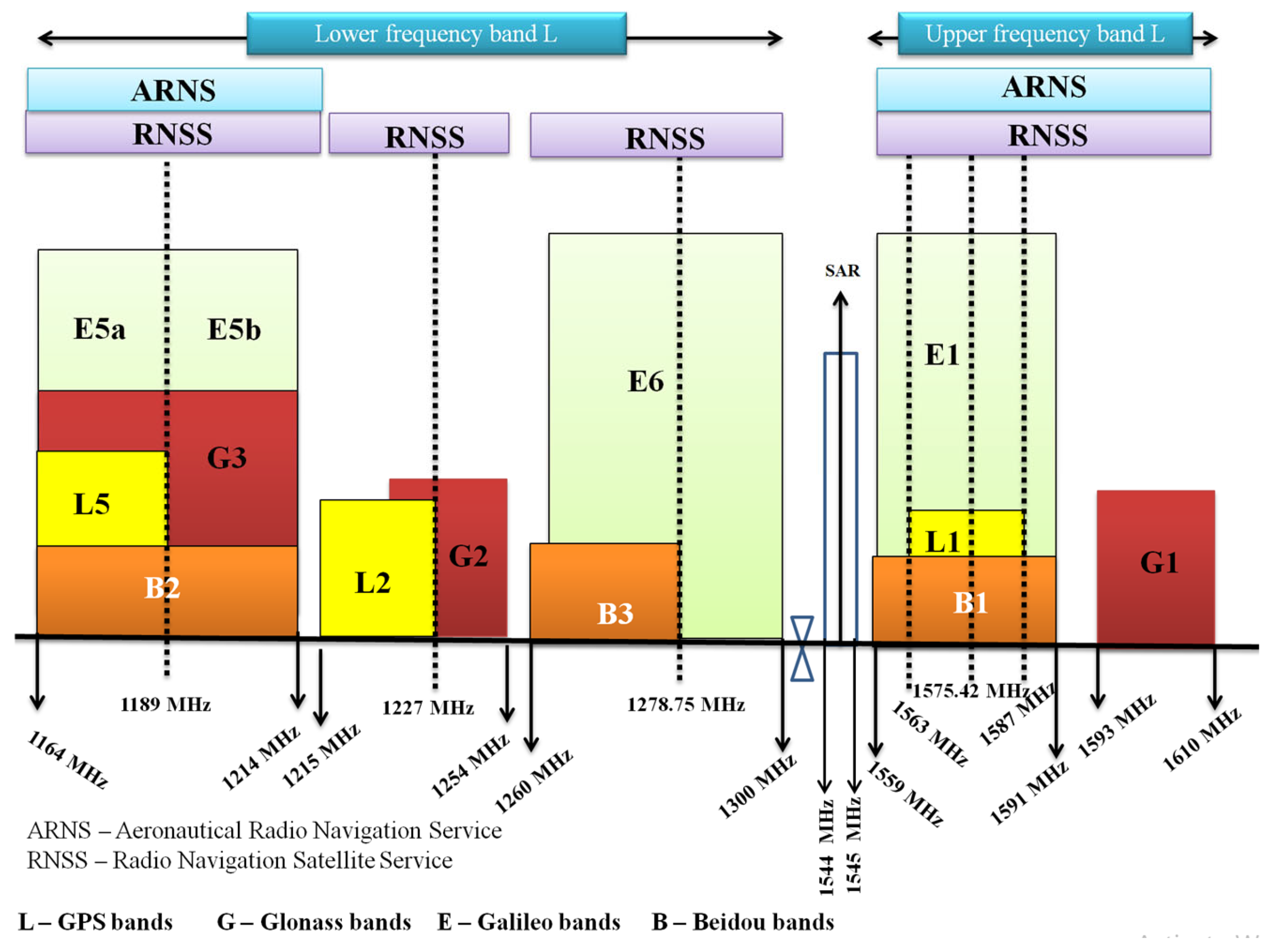
32]. This ensures that the antenna achieves maximum power transfer and operates within optimal parameters. In this study the desired frequency band is 1.559–1.591 GHz with an approximate resonance frequency of 1.575 GHz. This frequency band encompasses the GNSS frequency range allocated for aeronautical navigation services, which includes the frequency bands of the L1-GPS (Global Positioning System), E1-Galileo, G1-Glonass and B1-BeiDou satellite constellations as depicted in
Figure 1 [
17].
4. Results
Within this subsection, the analysis focuses on a square microstrip antenna that may undergo certain geometric modifications to its structure in order to achieve at the level of the radiated electromagnetic waves, an electric field with circular polarization or as close as possible to circular polarization [
21]. The antenna will be fed using a coaxial cable. This cable consists of a central conductor (a conductive material known as the “hot conductor”), which is surrounded by an insulating layer (a dielectric material) and finally enclosed in a shielding layer and an outer protective jacket. The coaxial cable will be selected based on its performance characteristics corresponding to the operating frequency, so as to ensure a characteristic impedance of 50 Ω [
37,
38].
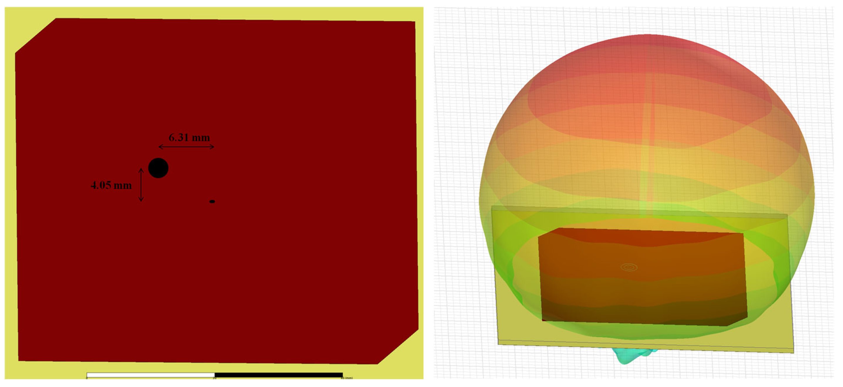
The resulting coaxially fed microstrip patch antenna is depicted in
Figure 4. It is implemented on a dielectric substrate of type RT Duroid 5880, characterized by a relative permittivity of
, a dissipation factor (loss tangent) of tg
.0004, and a substrate thickness of 1.575 mm. On the opposite side of the dielectric substrate, a ground plane is placed, constructed from the same conductive material as the radiating element, namely copper. The antenna is fed via a coaxial cable of type RG-142, which provides an input impedance of 50 Ω—required to properly feed the antenna and to ensure optimal impedance matching [
21]. The feed point was strategically positioned to ensure optimal impedance matching at 50 Ω ant to achieve the desired circular polarization. Specifically, relative to the center of the antenna, the feed point is located 6.31 mm along the Ox axis and 4.05 mm along the Oy axis. This positioning is clearly depicted in
Figure 4. The performance requirements of the antenna specify optimal operation within the frequency band of 1.559–1.591 GHz. This frequency range corresponds to the GNSS (Global Navigation Satellite System) spectrum allocated for aeronautical navigation services, covering the frequency bands used by the satellite constellations L1-GPS, E1-Galilleo, G1-GLONASS and B1-BeiDou [
17].
As indicated in
Figure 4, the microstrip antenna designed using the Ansys HFSS simulation and analysis software differs from a conventional patch antenna by the chamfering of two diagonally opposite corners, amounting to approximately 8% of the antenna’s length [
39]. In order to implement circular polarization, two orthogonal modes with equal amplitudes and a 90-degree phase difference must be excited. This is achieved by slightly perturbing the antenna geometry at specific locations, as shown in the aforementioned figure. This geometric modification facilitates the generation of circular polarization, while also contributing to an increased operational bandwidth and enhanced gain, due to the slight deformation of the patch’s shape [
21,
40].
Additionally, to further support the generation of circular polarization and to ensure optimal impedance matching, a coaxial feed was employed. The coaxial probe is position along the diagonal of the square patch, offset from the center by 6.31 mm along
Ox axis and 4.05 mm along
Oy axis [
21]. The most commonly analyzed parameter in antenna design is S
11, which represents the power reflected back to the antenna and is referred to as the reflection coefficient or return loss. For instance, an S
11 value of 0 dB indicates that all the power delivered to the antenna is reflected and no power is radiated. Conversely, an S
11 value of −10 dB implies that the antenna is matched, allowing for efficient power transfer. The power supplied to the antenna can either be dissipated as losses or radiated into free space. Ideally, all the power provided to the antenna should be radiated. Therefore, it is essential to ensure impedance matching between the antenna and the feed line in order to minimize power losses [
21,
41].
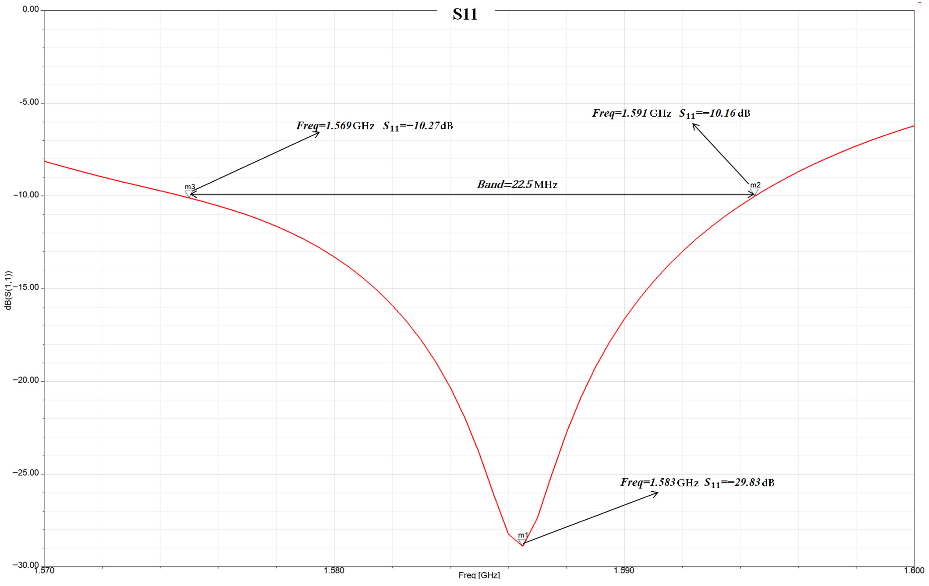
Figure 5 exposes the reflection coefficient S
11, illustrating the power transfer from the feed to the antenna.
According to
Figure 5, the designed antenna exhibits a minimum S
11 value of −29.83 dB at a resonant frequency of 1.583 GHz. The operational bandwidth is measured to be 22.5 MHz, spanning the frequency range from 1.569 GHz to 1.591 GHz, which covers approximately 70% of the targeted frequency band (it does not cover the frequency band defined by the interval 1.559 GHz to 1.569 GHz). The antenna’s bandwidth is defined by the frequency limits at which the return loss equals −10 dB, indicating proper impedance matching and efficient power transfer to the antenna. Notably, this frequency range includes 1.575 GHz, the central frequency shared by three satellite navigation constellations: L1-GPS, E1-Galileo and B1-BeiDou. Based on the variation in the S
11 parameter with respect to frequency, it can be observed that the proposed antenna covers approximately 70% of the Galileo constellation’s operational band, defined between 1.559 GHz to 1.591 GHz, with the antenna’s bandwidth extending from 1.569 GHz to 1.591 GHz. From the GPS constellation, whose operational band rangers from 1.563 GHz to 1.587 GHz, the designed antenna fully covers the entire allocated bandwidth. In the case of the BeiDou constellation, which shares the same operational band limits as Galileo, the antenna achieves a coverage of approximately 70% of the corresponding frequency range. As can be observed in
Figure 5, at 1.575 GHz, the return loss is −13.4 dB, which confirms a very good impedance match and effective power delivery at the frequency of interest [
42].
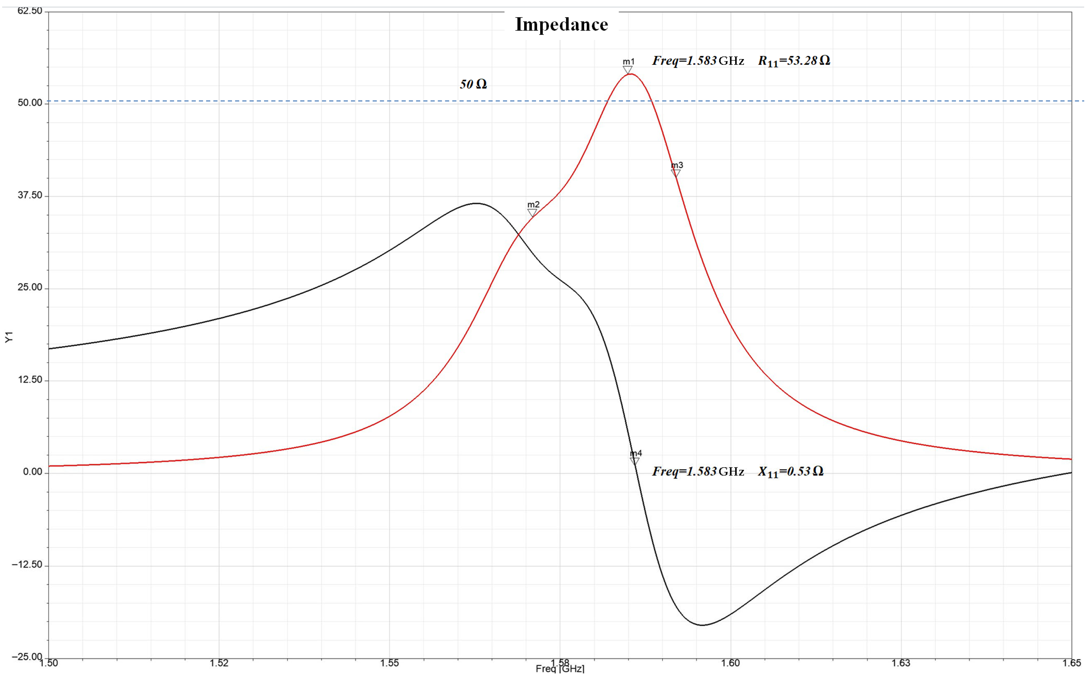
An important parameter that characterizes the antenna’s impedance matching and the efficiency of power transfer is Z
11, as shown in
Figure 6. In order to claim that the antenna is optimally matched, the real part of the input impedance should vary approximately linearly around 50 Ω, while the imaginary part (reactance) should exhibit a similar variation around 0 Ω. This behaviour is evident in the analysed antenna, where only minor deviations, within approximately 25% of the ideal impedance values are observed. These deviations occur primarily at the boundaries of the operational frequency band, which is an expected and acceptable outcome.
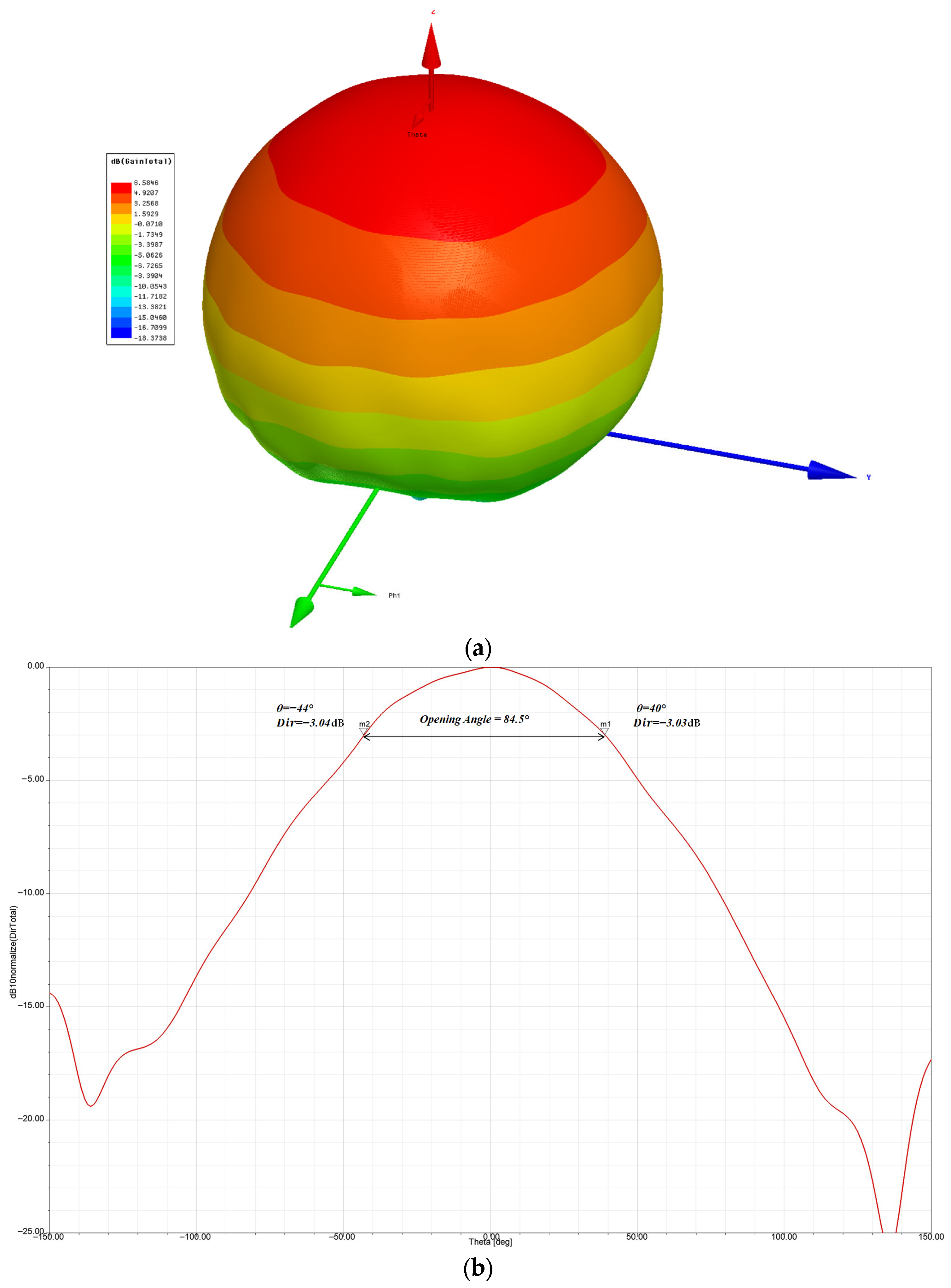
Other key parameters that characterize antenna performance are the antenna gain and the −3 dB beamwidth associated with the directivity pattern, which describes the spatial distribution of the radiated electromagnetic waves. These performance indicators are revealed in
Figure 7.
Based on the simulation results, it can be stated that the designed antenna exhibits a gain of 6.58 dB and a −3 dB beamwidth of θ = 84.5°. In order for the antenna to be suitable for integration into a GNSS receiver, in addition to the previously discussed parameters, it must exhibit circular polarization. This requirement was considered from the beginning by adopting a coaxial cable feeding method. In addition to the feeding technique, the antenna geometry was also adapted to achieve circular polarization by employing the geometric perturbation method, which involved introducing diagonally opposite corner cuts.
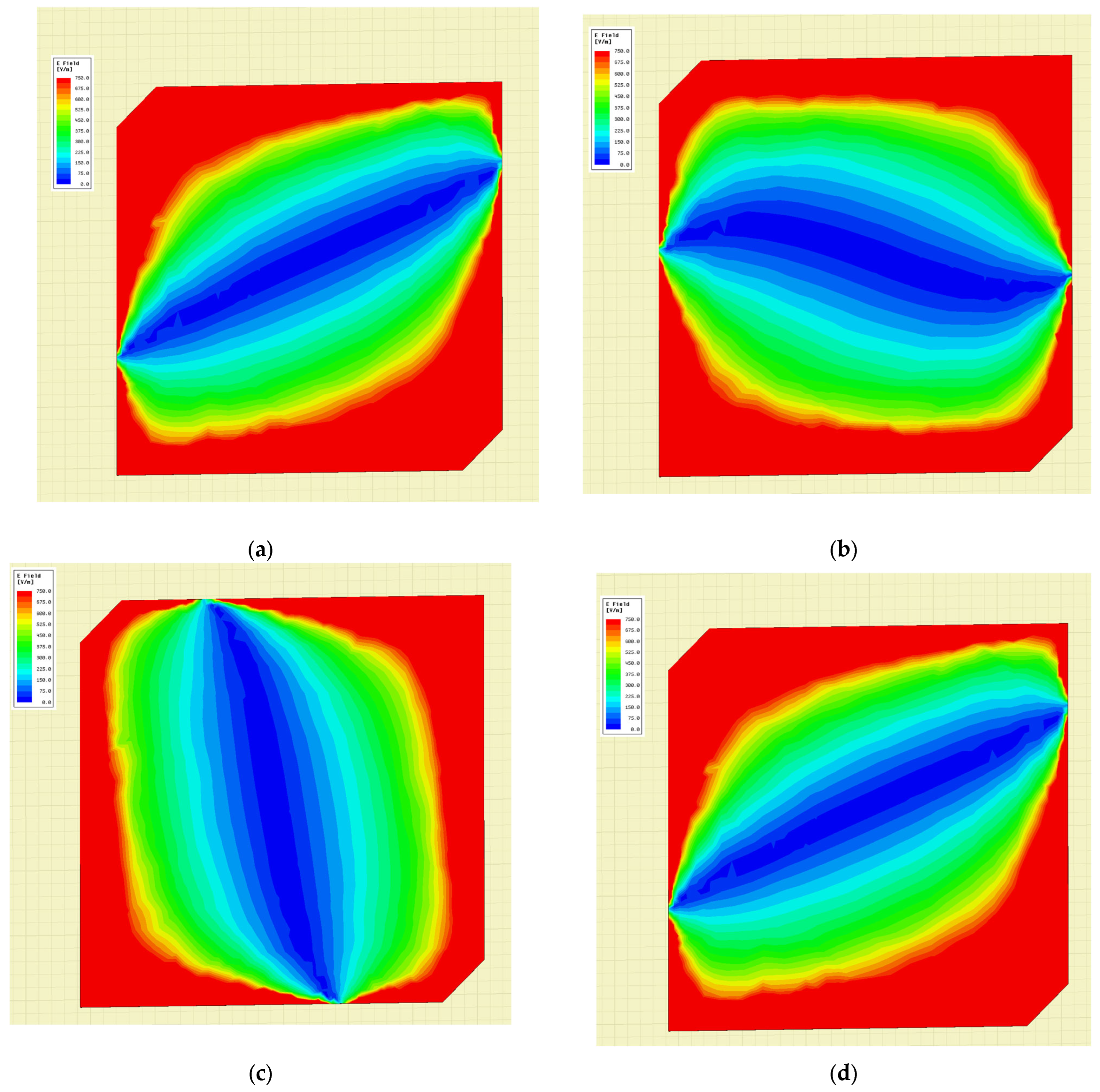
As shown in
Figure 8, the electric field distribution on the surface of the antenna at different angular positions
describes a circular trajectory, covering both the horizontal and vertical components of the electric field.
5. Discussion
Based on the results analysed above, it can be stated that the microstrip antenna can be successfully implemented in a GNSS, operating effectively within the desired frequency band and covering approximately 70% of the initially defined range. According to the reflection coefficient S11 values, the antenna exhibits an operational bandwidth of 22.5 MHz, which is considered narrow (a characteristic that is consistent with the intrinsic properties of microstrip antennas, known for their limited bandwidth).
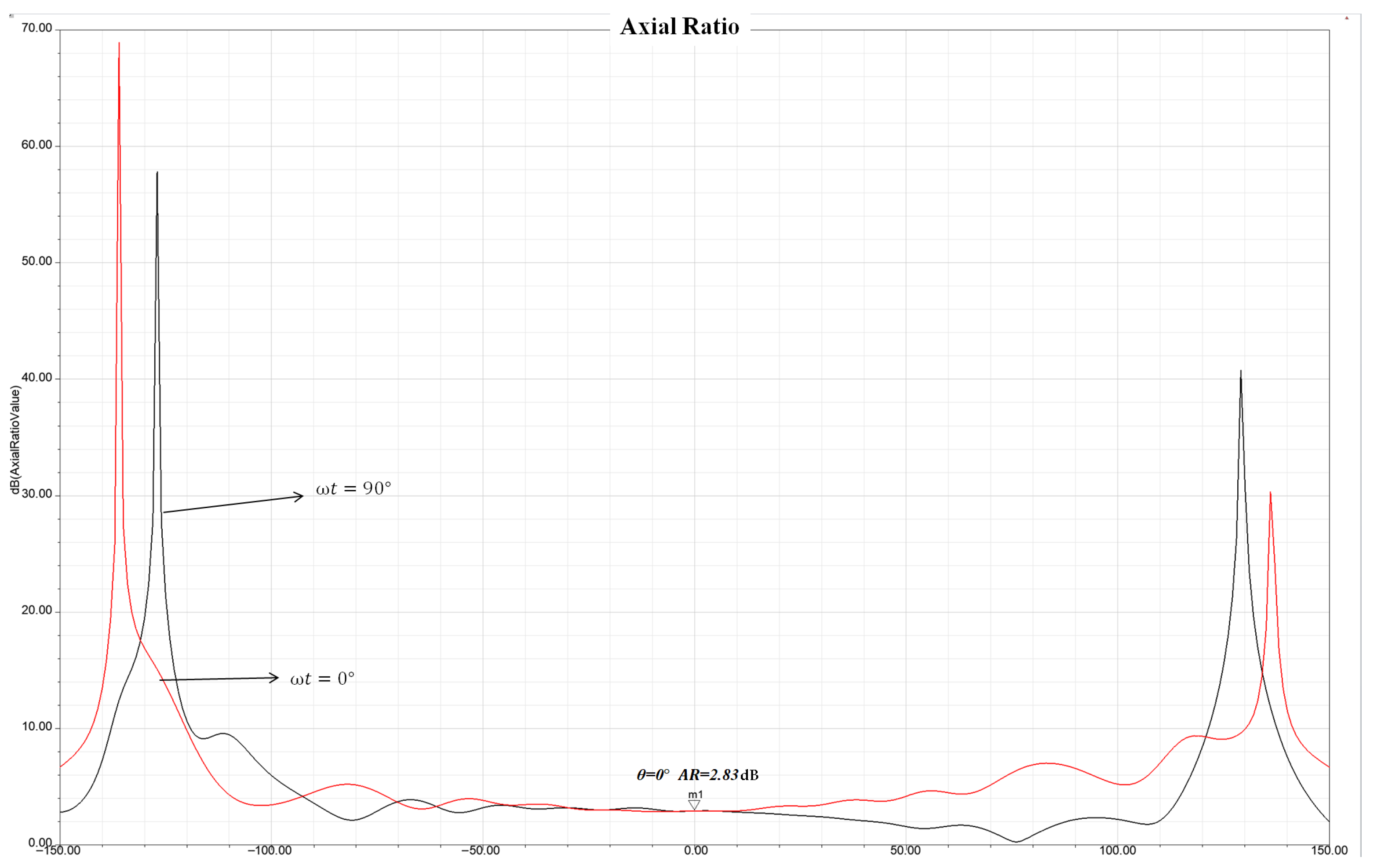
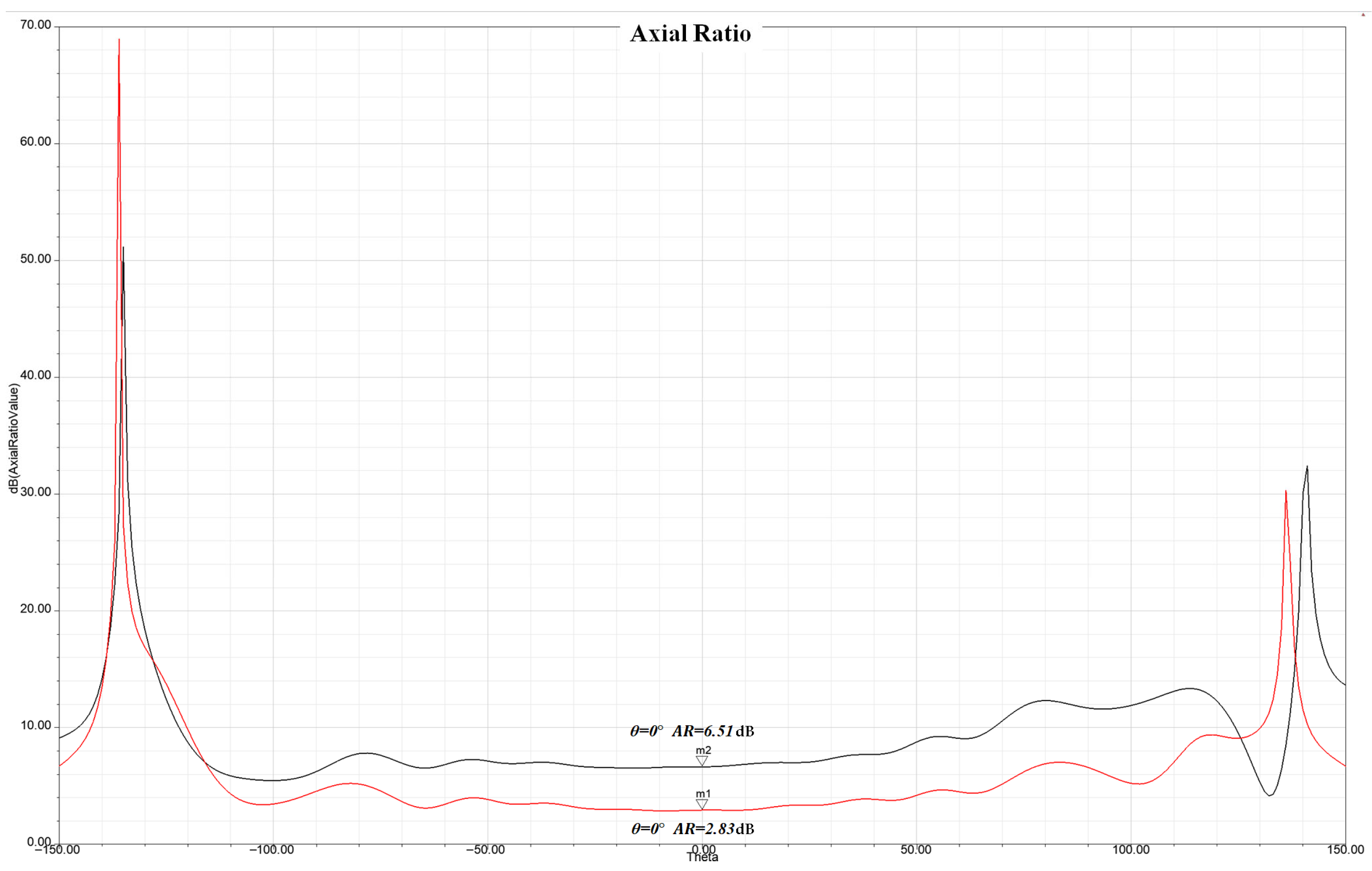
Figure 7 indicates that the antenna has a relatively wide beamwidth. Along the propagation direction defined by the −3 dB beamwidth, the antenna demonstrates circular polarization, as indicated by an Axial Ratio below 3 dB, as depicted in
Figure 9, an essential criterion for circular polarization. As initially required, the antenna was designed to exhibit circular polarization, given that signals transmitted by GNSS satellites predominantly possess this polarization. This property was achieved for the proposed antenna (originally exhibiting linear polarization) through the use of a coaxial feed technique and by geometrically modifying the diametrically opposite corners of the patch.
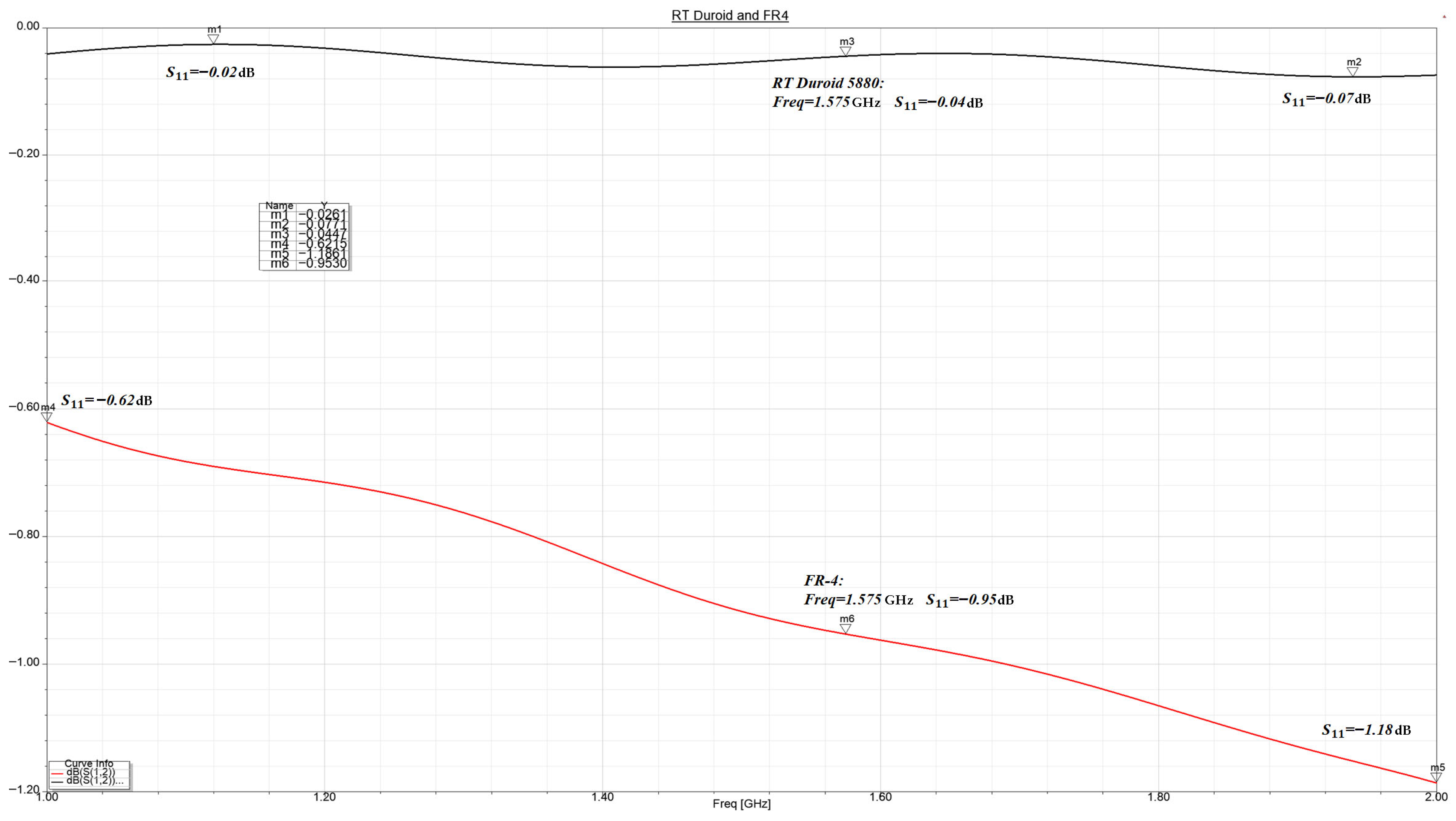
The materials used in the construction of the antenna have a significant impact on its overall performance. As shown in
Figure 3, the efficiency of power transfer to the antenna is notably influenced by the choice of materials, particularly the dielectric substrate. It can be observed that the FR-4 dielectric material introduces a maximum signal attenuation of −1.18 dB, nearly 15 times higher than the attenuation introduced by the RT Duroid 5880 substrate, which exhibits a maximum signal attenuation of only −0.077 dB. This comparison highlights the critical role of substrate selection in optimizing antenna performance, especially in high-frequency applications where signal losses must be minimized.
As can be observed, the early selection of materials, combined with the mathematical calculation of the antenna’s geometric configuration and the adaptation of the feeding system, represents a crucial aspect since the operational parameters of the antenna are directly influenced by these choices. The analysis proposed in this article, carried out by evaluating the dielectric substrates using a simple microstrip transmission line, has proven to be an efficient and rapid method for identifying signal attenuation, providing researchers with clear insights already in the preliminary design stage.
This approach is significantly different from that presented in the article by K.V. Rop et al. [
23], where the influence of dielectric materials is assessed by simulating the entire antenna structure. Such a method requires recalculating the geometrical dimensions for each substrate type, which results in higher computational costs, longer analysis time, and a more complex decision-making process when selecting the optimized variant.
By contrast, the present work not only emphasizes the preliminary evaluation of materials but also integrates their selection with minimal attenuation and distortion, in parallel with the optimization of the antenna geometry and the feed point, in order to ensure compliance with the requirements and performance characteristics expected of a GNSS antenna.
It is important to highlight that throughout the simulations and design calculations, the geometric location of the antenna’s feed point was found to have a significant influence on performance. As depicted in
Figure 10, variations in the feed point position resulted in differences of approximately 3 dB in the axial ratio parameter. The axial ratio is defined as the ratio between the maximum and minimum magnitudes of the electric field vector. These findings emphasize the critical role of precise feed point placement in achieving the desired polarization characteristics, particularly in applications requiring circular polarization.
6. Conclusions
Following the simulations conducted on the antenna designed for GNSS applications in the aerospace field, several clear conclusions can be drawn regarding both the simulation methodology and the performance of the microstrip patch antenna fed via a coaxial cable, intended for integration into a GNSS receiver for aerospace use. The simulations, performed using the Ansys HFSS (Ansoft) software, revealed the influence of the construction materials on antenna performance. As initially defined, the dielectric substrate used was RT Duroid 5880, characterized by a relative permittivity = 2.2, a loss tangent tg = 0.0004 and a dielectric thickness of 1.575 mm. The ground plane, placed on the opposite side of the dielectric substrate, was made of copper, similar to the conductive layer of the designed antenna. The antenna was fed using an RG-142 coaxial cable, which provides a 50 Ω input impedance. The feed point was located diagonally from the center of the square patch, specifically 6.31 mm along the x-axis and 4.05 mm along the y-axis. This positioning was chosen to achieve optimal impedance matching for improved performance. The analyses conducted led to the identification of an operating frequency band ranging from 1.569 GHz to 1.591 GHz, covering approximately 60% of the initially targeted bandwidth. The return loss value of S11 = −29.83 dB at the center frequency of 1.575 GHz indicates good impedance matching and efficient power transfer to the antenna, as the return loss is significantly below the commonly accepted threshold of −10 dB. It is characteristic of microstrip antennas to exhibit a narrow bandwidth, an aspect also observed in this study. However, despite the limited bandwidth, the antenna effectively covers the frequency of interest, 1.575 GHz, which is the central frequency used by the three major satellite constellations: L1-GPS, E1-Galileo and B1-BeiDou. Moreover, the return loss at this frequency remains low, with a measured value of S11 = −13.4 dB, ensuring optimal impedance matching and minimal signal reflection. It can therefore be concluded that the feed point of the antenna was strategically positioned to maximize power transfer while minimizing return loss. At the same time, this configuration ensures circular polarization, which is essential for the effective reception of electromagnetic wave transmitted by GNSS satellites toward the receiver.
As confirmed by the simulation results and by
Figure 10, the positioning of the feed point plays a critical role in the overall performance of the antenna. The obtained axial ratio value of −2.83 dB confirms the presence of circular polarization as it falls below the conventional upper limit of −3 dB. Another factor supporting the existence of circular polarization is the electric field distribution over the antenna surface, as shown in
Figure 8, corresponding to phase angles
,
,
and
. This spatial field behavior further validates the polarization characteristics. A major advantage of the analysed antenna and the adopted microstrip implementation lies in its relatively high gain of 6.58 dB, combined with a wide beamwidth of 84.5°. These characteristics demonstrate that the antenna is a suitable candidate for integration as a radiating element in antenna array systems. A significant advantage of the antenna structure is its lightweight design, compact dimensions and reduced mass (the dimensions of the microstrip antenna are estimated at approximately 65 mm × 65 mm, with a dielectric substrate thickness of 1.575 mm made of RT Duroid 5880, the substrate density being approximately 2.2 g/
and the estimated total mass of the antenna around 7 g), which make it suitable for integration into the structure of an aircraft or an UAV.
The simulation results are specific and relevant to the proposed antenna geometry, the targeted frequency band, the selected dielectric material and the design techniques employed. This combination of factors, refined through successive optimizations, leads to notable antenna performance for GNSS applications, giving this work a strong practical and application-oriented value. To conduct an effective analysis of the proposed microstrip patch antenna for GNSS applications, several reference studies were reviewed. Additionally, to emphasize the originality of the proposed design (based on the strategic integration of three key factors: geometric modification, feeding technique and dielectric material selection), a set of relevant comparisons is presented in the Introduction section, as well as a comparison with another reference cited below.
For instance, Mathur et al. [
43] studied a microstrip antenna on RT Duroid 5880 and FR-4 dielectric substrates, providing a comparison of the obtained results. However, it is important to note that, unlike the antenna analyzed in the present manuscript, their antenna was fed using a simple transmission line without geometric adjustments to achieve circular polarization. In contrast, the present study aims to achieve circular polarization through a strategic combination of feeding method and antenna geometry, resulting in performance suitable for implementation in aerospace applications.
In conclusion, the original contribution of this study lies in the simultaneous optimization of antenna geometry, feeding method and dielectric material selection. This integrated approach has led to notable improvements in antenna gain, axial ratio and impedance matching across the targeted GNSS frequency bands. The primary objective of this paper is to develop an efficient and simplified microstrip antenna configuration by coherently integrating multiple design technique to achieve the electromagnetic and functional performance required for GNSS applications.
Therefore, based on the simulation results and the performance metrics obtained, it can be concluded that the analysed microstrip patch antenna exhibits all the necessary characteristics for implementation in GNSS applications relevant to the aerospace domain.
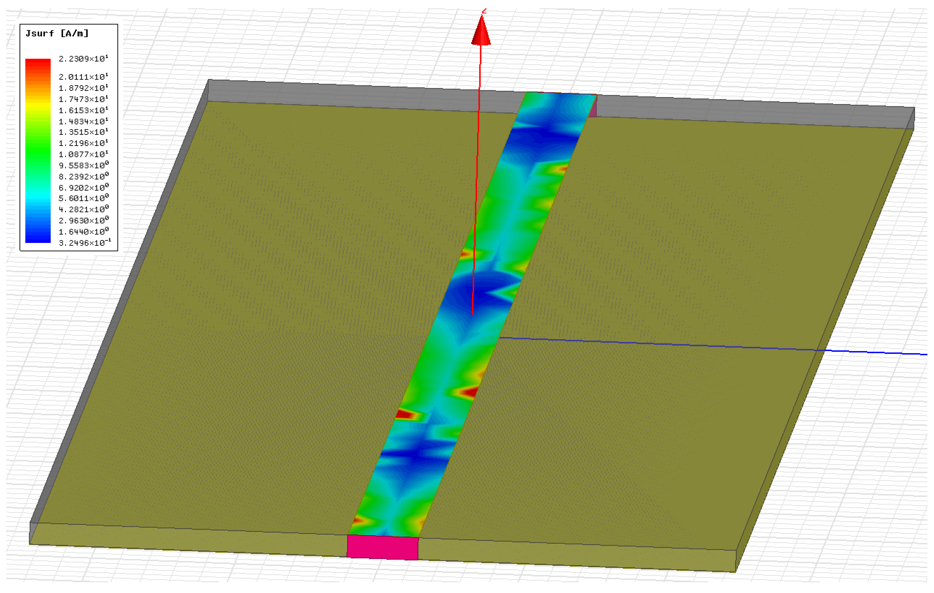
 ) FR-4 and (
 ) RT Duroid 5580.
 resistance) and imaginary (
 reactance) components of the antenna impedance.