Article

Preparation of Microlens Array Using Excimer Laser Motion Mask

School of Physics and Optoelectronic Engineering, Beijing University of Technology, Beijing 100124, China
*
Author to whom correspondence should be addressed.
Appl. Sci. 2025, 15(19), 10664; https://doi.org/10.3390/app151910664
Submission received: 30 April 2025 / Revised: 12 September 2025 / Accepted: 26 September 2025 / Published: 2 October 2025

Abstract

Featured Application

The high single-photon energy of excimer lasers can achieve cold laser processing of PMMA materials, which is beneficial for fine processing. This article analyzes the specific exposure mask and its preparation principle, which does not require the use of chemical reagents and is conducive to promotion and widespread use in the preparation of MLAs. A transient 3D model is established to simulate the preparation process of microlenses, and the visualization level of the preparation process is improved.

Abstract

In order to optimize the preparation process of microlens arrays, improve preparation efficiency, and reduce preparation costs, 248 nm KrF excimer laser direct writing is combined with a motion mask to prepare microlens arrays on PMMA substrates. Firstly, a specific exposure mask based on the contour characteristics of the microlens unit was designed, and the preparation principle was analyzed. Using COMSOL Multiphysics 6.3 simulation software, a microlens preparation model was built to intuitively describe the process of preparing microlenses by the motion mask method. Secondly, a preparation system was built, and the laser processing technology was optimized. Finally, microlens arrays were prepared based on the optimized process, and an optical microscope and white-light interferometer were used to observe their morphology. The experimental results show that this method can effectively prepare cylindrical and circular microlens arrays. The width of the cylindrical microlens array unit exceeded 90 μm, the height was 7.08 μm, and the roughness was 0.09 μm. The diameter of the circular microlens array unit was φ100 μm, the height was 4 μm, and the curvature radius was 230 μm. The geometric dimensions of the mask can be adjusted to obtain microlens units of the desired size, achieving personalized preparation of microlens arrays. The excimer laser motion mask method can prepare various types of microlens arrays, and the array units have a high consistency and high surface quality, which helps to improve the efficiency, flexibility, stability, and specificity of microlens array preparation.

1. Introduction

A microlens array (MLA) is a small-sized and highly integrated micro-optical device. Due to their special geometric features, MLAs can realize a variety of optical functions, such that they are widely used in optical imaging, optical sensing, beam shaping, artificial compound eyes, and other fields [1,2,3,4]. MLAs can be prepared on inorganic and organic materials such as silicon, quartz glass, liquid crystal, and polymethylmethacrylate (PMMA) [5]. With the rapid development of laser micro–nano processing technology, a major breakthrough in the non-contact preparation of MLA has been made, which greatly promotes the development of optical device preparation [6]. The excimer laser is a short wavelength ultraviolet laser with the advantages of easy absorption, low penetration depth, and high photon energy. It can directly sublime surface materials by breaking chemical bonds through photochemical reactions [7]. It has almost no thermal effect on the processed material and low internal damage, and it can achieve high-precision preparation of fine features [8,9]—playing an important role in the field of micro–nano manufacturing.
In recent years, extensive research on MLA fabrication technologies has been conducted by experts and scholars from various institutions. H. Ottevaere [10] provided a comprehensive overview of microlens fabrication techniques developed from the 1980s to the 2000s, which included thermal reflow or resist melting methods, direct writing of microlenses, deep lithography with protons (DLP), laser-ablated microlenses, and microjet printing. Dejian Kong [11] from Central South University developed a spatially modulated picosecond laser system that transformed a Gaussian beam into multifocal spots and a line-shaped beam. After multi-focal spot ablation and subsequent chemical treatment, the resulting micro-craters exhibited maximum diameters of 1.9 μm and depths of 22.1 μm. By combining femtosecond laser modification with an ion beam etching process [12], concave MLAs can be fabricated on superhard materials. Leveraging these two high-precision techniques, the focal lengths of the microlenses can reach 60–100 μm. Zixiao Zhang [13] from Harbin Institute of Technology fabricated quartz MLAs through rapid ablation and polishing using a CO2 laser, with optical performance remaining stable across a 200–400 μm range. Li Qiankun [14] from Tsinghua University achieved rapid fabrication of glass MLAs by integrating laser etching with high-temperature casting and transcription technology, offering a valuable reference for the rapid prototyping of micro–nano devices from hard materials. Abolfazl [15] demonstrated the replication and transfer of MLAs between PMMA and nickel substrates via electroforming, obtaining highly consistent PMMA MLAs. Jungho Yi [16] formed PDMS droplets through pores on PTFE films and cured them over several hours to produce MLAs with a diameter of 500 μm, a height of 100 μm, and an inter-lens interval of 1.4 mm. Although scholars have conducted numerical simulations on the thermal process [17,18,19] and process parameter exploration [20] of laser manufacturing, studies focusing on the formation mechanisms of specific morphologies remain limited.
In this study, a transient three-dimensional (3D) model of the microlens motion mask fabrication process was developed using COMSOL Multiphysics simulation software, and numerical simulations of the MLA preparation process were performed. Computational results reveal the morphological evolution from the initial substrate to the final microlens structure, clearly illustrating the fabrication dynamics and providing deeper insight into short-pulse laser motion etching. Furthermore, the model enables parametric analysis for systematic process optimization, thereby contributing to cost reduction and efficiency improvement. Experimentally, both cylindrical and circular MLAs were successfully fabricated. Surface characterization confirms the complete formation of the MLAs structures with excellent uniformity, demonstrating their suitability for large-scale production and replication.

2. Materials and Methods

2.1. Principle Model for the Preparation of Microlens Arrays

2.1.1. Principle Analysis Model of Excimer Laser Motion Mask Method

MLAs are fabricated on polymethylmethacrylate (PMMA) substrates. As shown in Figure 1, the pulsed excimer laser passes through a customized exposure mask with symmetrically distributed apertures, which are geometrically defined as the set difference between rectangular and semicircular shapes. When the PMMA substrate is irradiated by a single excimer laser pulse, the mask pattern is transferred onto the substrate via selective etching. Under multi-pulse excimer laser irradiation combined with a 3D motion system, discrete etched microstructures are generated on the substrate. During the stable phase of multi-pulse etching, the cumulative laser fluence on the PMMA substrate gradually decreases from the center to the edge along the direction perpendicular to the symmetry axis. Correspondingly, the material removal depth varies spatially, transitioning from greater etching at the center to lesser etching toward the periphery. Through this process of cumulative irradiation etching using a specifically designed mask, the two-dimensional (2D) pattern is successfully transformed into a 3D microlens configuration, enabling the fabrication of MLAs.
Upon completing irradiation scanning along direction 1, a set of cylindrical microlenses are etched onto the substrate surface. The cylindrical microlenses are a convex profile with raised central and lowered edges. The specific exposure mask is then rotated by 90°, and scanning is performed along direction 2, perpendicular to direction 1, thereby etching a second set of cylindrical microlenses with similar cross-sectional geometry. At the inter-sections of these two orthogonal sets of cylindrical structures, individual circular microlenses are formed. Thus, the MLA is fabricated by sequentially etching parallel cylindrical lens groups along direction 1 and direction 2. The working principle of the excimer laser motion mask method for MLA fabrication is illustrated in Figure 2, and the corresponding process flow is summarized in Figure 3.

2.1.2. Mathematical Model of Excimer Laser Motion Mask Method

The fabrication of MLA via the motion mask method necessitates stable laser energy delivery and a precise mask pose. The resulting MLA morphology is influenced by key process parameters including exposure size, pulse frequency, and scanning speed. Accordingly, a mathematical model is developed to systematically analyze the correlation between these parameters and microlens formation characteristics.
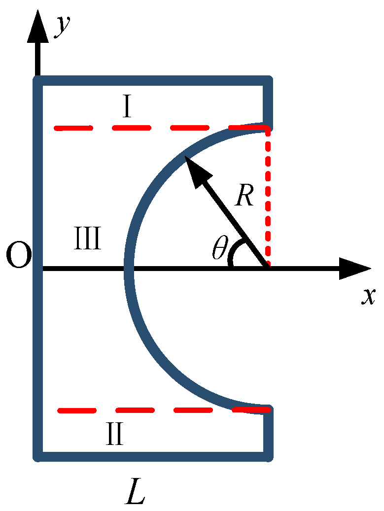
The geometric features of the exposure mask are extracted, and a coordinate system is established with the symmetrical axis of the features as the X-axis, as illustrated in Figure 4. The geometry is divided into three regions: I, II, and III. Key parameters include the arc radius R, the angle θ between radius and X-axis, and the length L. In addition, the excimer laser pulse frequency f and scanning speed v are defined. Based on these parameters, a mathematical model is formulated to describe the process.
Based on the physical model of multi-pulse etching, the fabrication of MLA via the motion mask method requires that the substrate be exposed at least twice within the length L. This implies that the laser frequency f and scanning speed v must satisfy the following condition:
L > v f
Within the length L, the total number of exposure pulses received by the substrate can be expressed as N1 for areas I and II, and N2 for area III, as in the following expressions:
N 1 = L v f
N 2 = L - R cos θ v f θ π 2 , π 2
Based on expressions (2) and (3), during the multi-pulse motion etching process, the cumulative exposure energy received by the substrate in areas I and II remains uniform along the y-direction. Consequently, the material removal depth induced by the excimer laser is also identical in these areas. In contrast, within area III, the cumulative exposure along the y-direction increases smoothly from the center toward the edge, resulting in a corresponding gradient in the material removal depth.
N 1 N 2 = L L - R cos θ θ π 2 , π 2
According to expression (4), the morphology of a cylindrical microlens produced by multi-pulse motion etching is determined by two key mask parameters: length L and radius R. The final cylindrical form is a direct consequence of the symmetrical material removal gradient, where the etch depth varies progressively with radial distance from the central axis.
Model analysis reveals that the parameters L and R of the specific exposure mask govern the spatial distribution of material removal. By controlling the laser pulse frequency and scanning speed to cumulatively modulate this distribution, a cylindrical convex microlens with a smooth height gradient from the symmetry axis to the periphery can be fabricated. Furthermore, a circular convex microlens can be achieved by combining orthogonal etching paths.

2.2. Numerical Calculation of Microlenses Prepared by Motion Mask Method

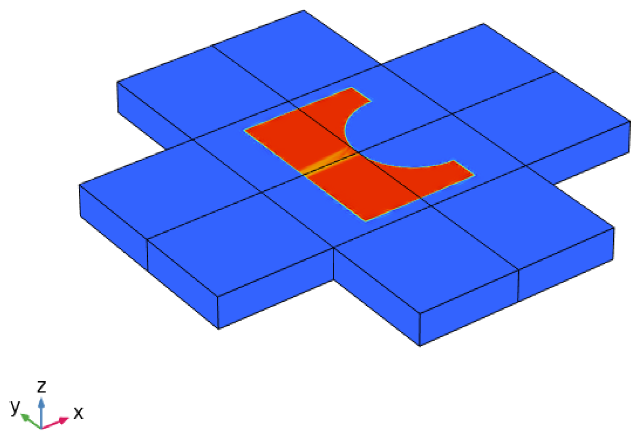
To provide a more intuitive visualization of the microlens fabrication process, a 3D transient model of the motion mask method was constructed using COMSOL Multiphysics simulation software. The model comprises two core components: PMMA material definition and multi-pulse nanosecond excimer laser irradiation configuration.
The properties of PMMA in the model are determined by density, heat capacity, and thermal conductivity, among which density ρ = 1190 kg/m3, heat capacity c = 1420 J/(kg·K), and thermal conductivity k = 0.2 W/(m·K). The pulsed excimer laser loading meets the requirements of pulse width τ = 30 nm, frequency f = 25 Hz, and scanning speed v = 0.02 mm/s. Table 1 lists information on the PMMA materials and Table 2 lists information on excimer laser loading. The energy distribution of the PMMA material irradiated by the excimer laser in numerical calculation is shown in Figure 5.
The numerical simulation results are presented in Figure 6. At t = 0.04 s, corresponding to the completion of the first pulse cycle, the characteristic etching profile of the mask is replicated onto the PMMA substrate. With continued scanning, the etch depth progressively increases. By t = 2 s, when the scanning length equals length L, the maximum etching depth in direction 1 is attained. A well-defined cylindrical etched morphology is formed by t = 4 s. Subsequent scanning in direction 2 selectively removes additional material from the cylindrical microstructure, ultimately generating a convex microlens profile characterized by a raised center and lowered periphery.
Figure 7 illustrates the evolution of the etching morphology on the y–z and x–z planes. At the initial stage (t = 0 s), both planes exhibit identical profiles. By t = 4.6 s, when etching along direction 1 is completed, a cylindrical morphology characterized by a raised center and depressed edges is observed in the y–z plane, while the x–z plane displays a uniform etching height throughout the processed region. Upon completion of etching in direction 2 at t = 9.28 s, both cross-sections exhibit convex microlens profiles with elevated centers and lowered peripheries, confirming the successful fabrication of the microlens structure.

2.3. Experimental System and Procedures

2.3.1. Experimental System

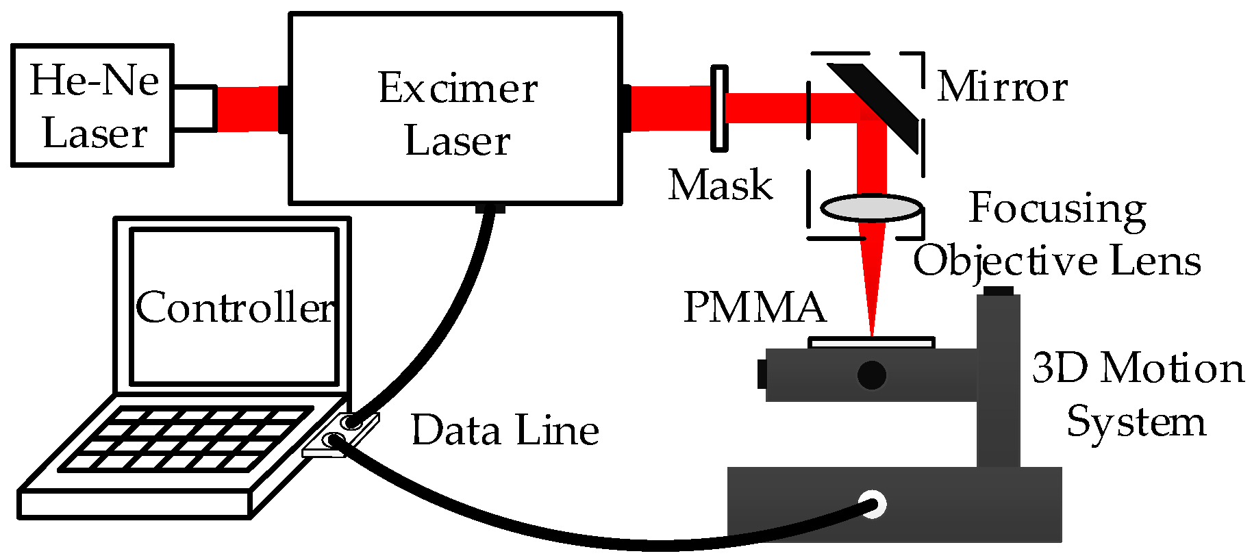
The experimental system for fabricating MLAs via the excimer laser motion mask method is illustrated in Figure 8. The system consists of a pulsed excimer laser, a coaxial He–Ne laser, specific exposure mask, a mirrors, a focusing objective lens (20:1), a 3D motion system, and a system controller. The He–Ne laser, aligned coaxially with the excimer laser, serves as a visual guide to trace the path of the invisible ultraviolet beam and assist in substrate positioning. The excimer laser beam passes through the exposure mask to generate a specific pattern, which is then reflected and focused onto the PMMA substrate for direct write etching. Both the excimer laser irradiation and the 3D motion system are synchronized under the control of a central controller.

2.3.2. Experimental Method

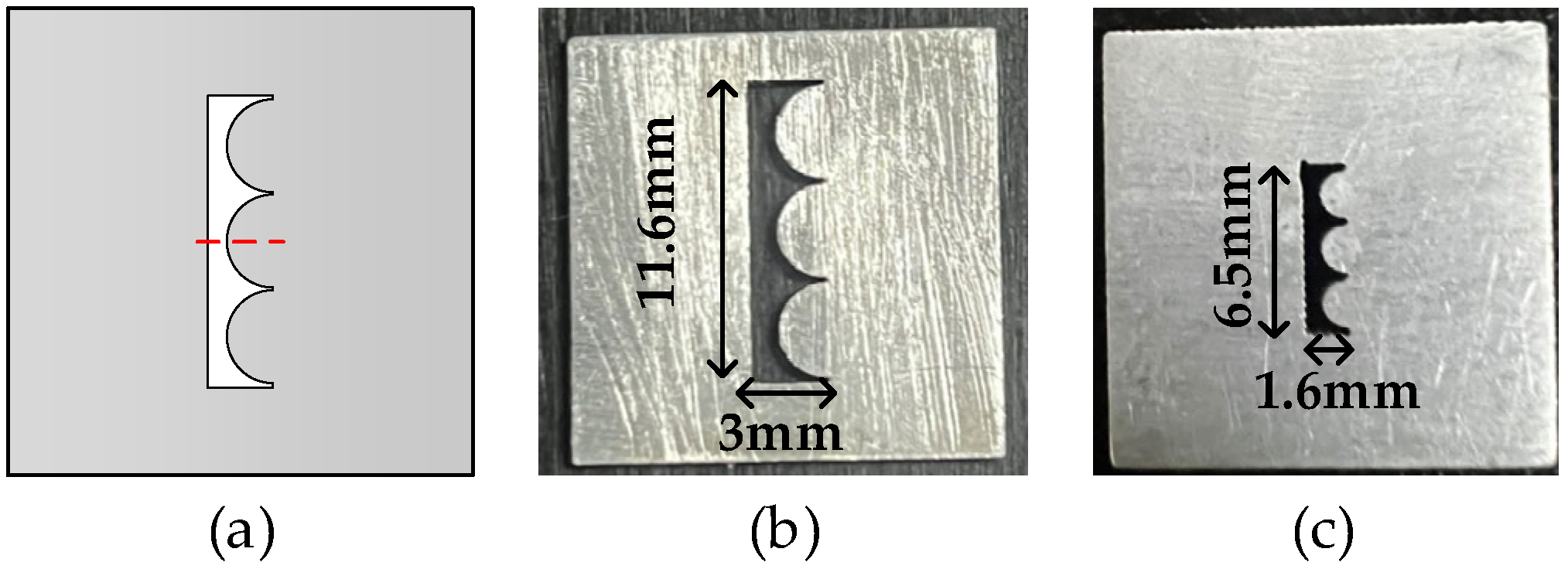
The PMMA substrate with dimensions of 100 mm × 100 mm × 3 mm was cleaned using an ultrasonic cleaner and subsequently air-dried. To improve the fabrication efficiency, a customized specific exposure mask was developed, as illustrated in Figure 9. This mask was fabricated from 0.3 mm thick stainless steel by laser cutting.
The excimer laser was operated with an output energy of approximately 720 mJ, pulse frequency f = 10 Hz, and scanning speed v = 0.04 mm/s. A focusing objective lens was employed to demagnify the mask pattern by a factor of approximately 19:1. As a result, the theoretical values of the optical transmission length L for mask-1 and mask-2 were calculated to be approximately 157 μm and 82 μm, respectively. These parameters satisfy the condition specified in the expression, thereby enabling the successful preparation of the MLAs.

3. Results and Discussion

3.1. Principle Verification

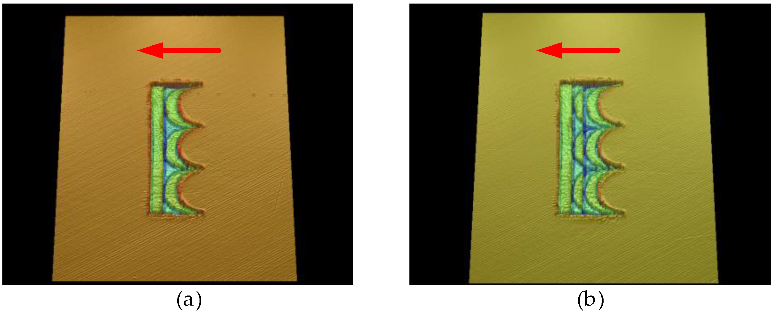
In accordance with the process outlined in Figure 3, single-pulse fixed-point etching and multi-pulse motion etching experiments were performed to validate the working principle of the motion mask method. The corresponding results, as characterized by white-light interferometry, are presented in Figure 10, wherein mask-1 was employed in these experiments.
Observing the etching result of single-pulse fixed-point under a 5× white-light interferometer, there is a well–defined morphology with sharp edges and the etching depth approximately 1.25 μm. The measured side lengths of the two characteristic segments are 605 μm and 158 μm, respectively, consistent with the designed dimensions. The exposure mask, magnification factor of the focusing objective, and dimensions of etching morphology are summarized in Table 3. The result confirm that the excimer laser is suitable for PMMA processing, thereby validating the feasibility of subsequent fabrication steps.
To elucidate the motion etching process more clearly, experiments with two-pulse and three-pulse etching were conducted allowing 50 μm between each pulse. The corresponding results are presented in Figure 11.
The measurement results show that during etching along the arrow direction, each subsequent pulse is superimposed onto the trace of the preceding pulse—resulting in repeated exposure of localized areas. The measured etching depths in the overlapping regions were approximately 2.63 μm for the two-pulse process and 5.11 μm for the three-pulse process. These results demonstrate that the etching depth increases progressively during the unstable etching phase, but subsequent pulses do not entirely erase the traces of earlier pulses. During the stable phase, this phenomenon still exists, but it is significantly improved.

3.2. Measurement of Cylindrical Microlens Morphology

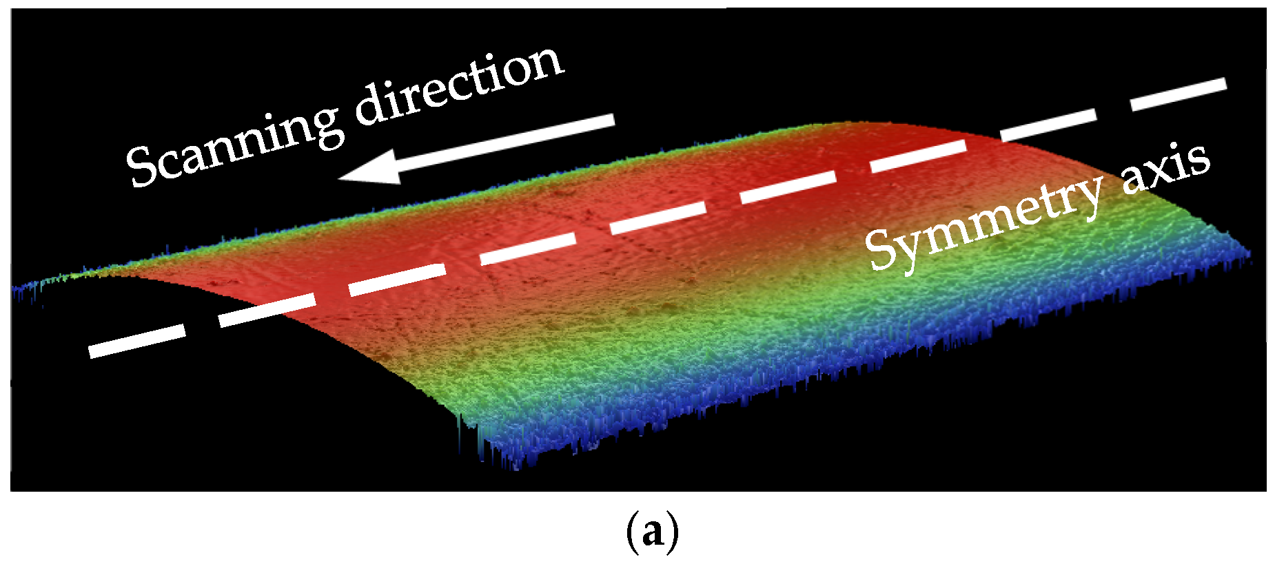
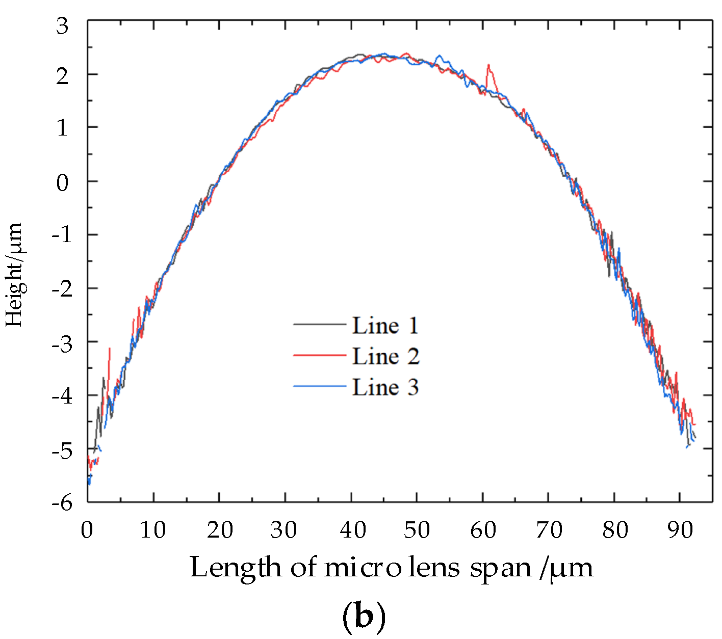
Figure 12 presents the measurement results of cylindrical microlens characterized using 50× white-light interferometer. The cylindrical microlens array was fabricated using mask-2. The microlens profiles exhibit symmetric geometry, characterized by an elevated center and a gradually descending edge. Surface profiles were extracted along three parallel lines oriented perpendicular to the symmetry axis for quantitative analysis. The measured profiles reveal a maximum height difference of approximately 7.08 μm and a tangential span exceeding 90 μm.
Cylindrical microlenses were successfully fabricated by this method. Surface profiles were acquired at three distinct positions, revealing highly consistent morphological characteristics with strong uniformity. The surface roughness values are approximately 70 nm along the x-direction and 100 nm along the y-direction. The surface texture can be attributed to the discrete nature of pulsed laser etching, where the temporal separation between successive pulses leads to non-uniform material removal. Furthermore, the overlapping of etching boundaries exacerbates this inhomogeneity. Future work may explore post-processing techniques such as laser polishing to reduce surface roughness and enhance optical performance.
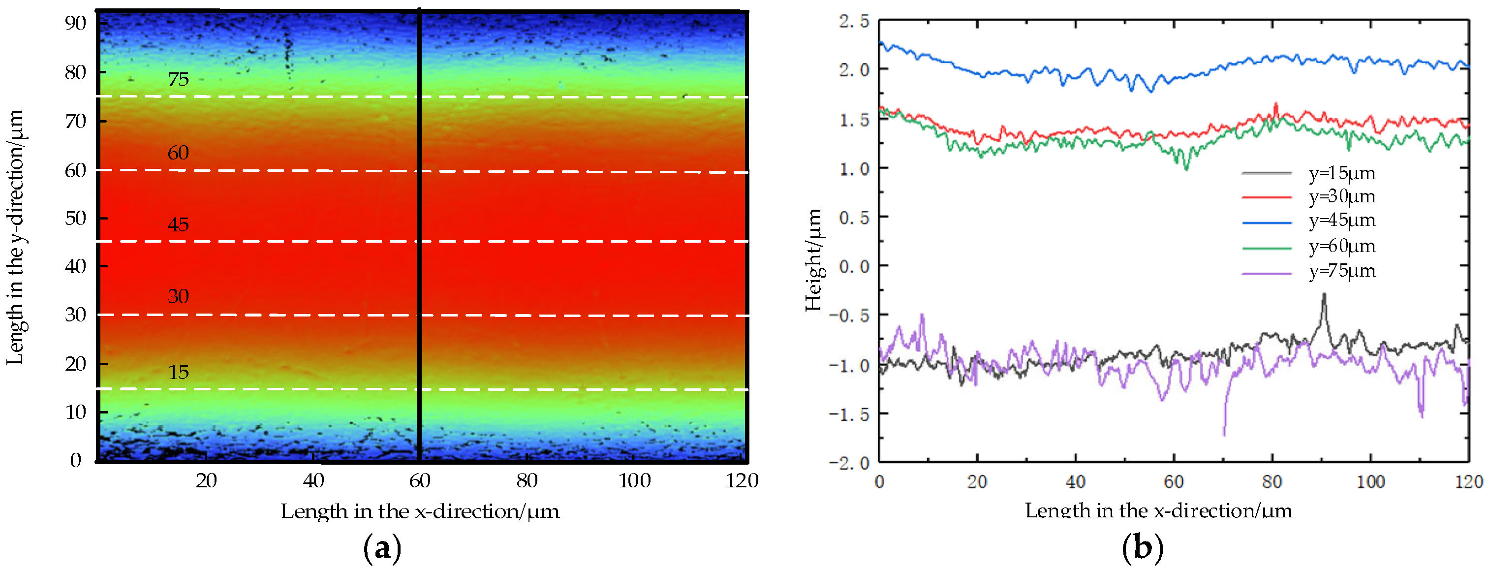
As shown in Figure 13, height profiles were extracted at x = 60 μm along five parallel lines corresponding to y = 15 μm, 30 μm, 45 μm, 60 μm, and 75 μm, respectively. The average heights of these profiles exhibit a symmetric distribution, with measured values of −0.89 μm, 1.41 μm, 2.02 μm, 1.30 μm, and −0.99 μm. The average surface roughness across the profiles is 90 nm, with individual standard deviations of 0.13, 0.08, 0.09, 0.10, and 0.14, respectively. These consistently low deviation values indicate that the fabricated cylindrical microlens possesses excellent surface flatness.

3.3. Measurement of Circular Microlens Morphology

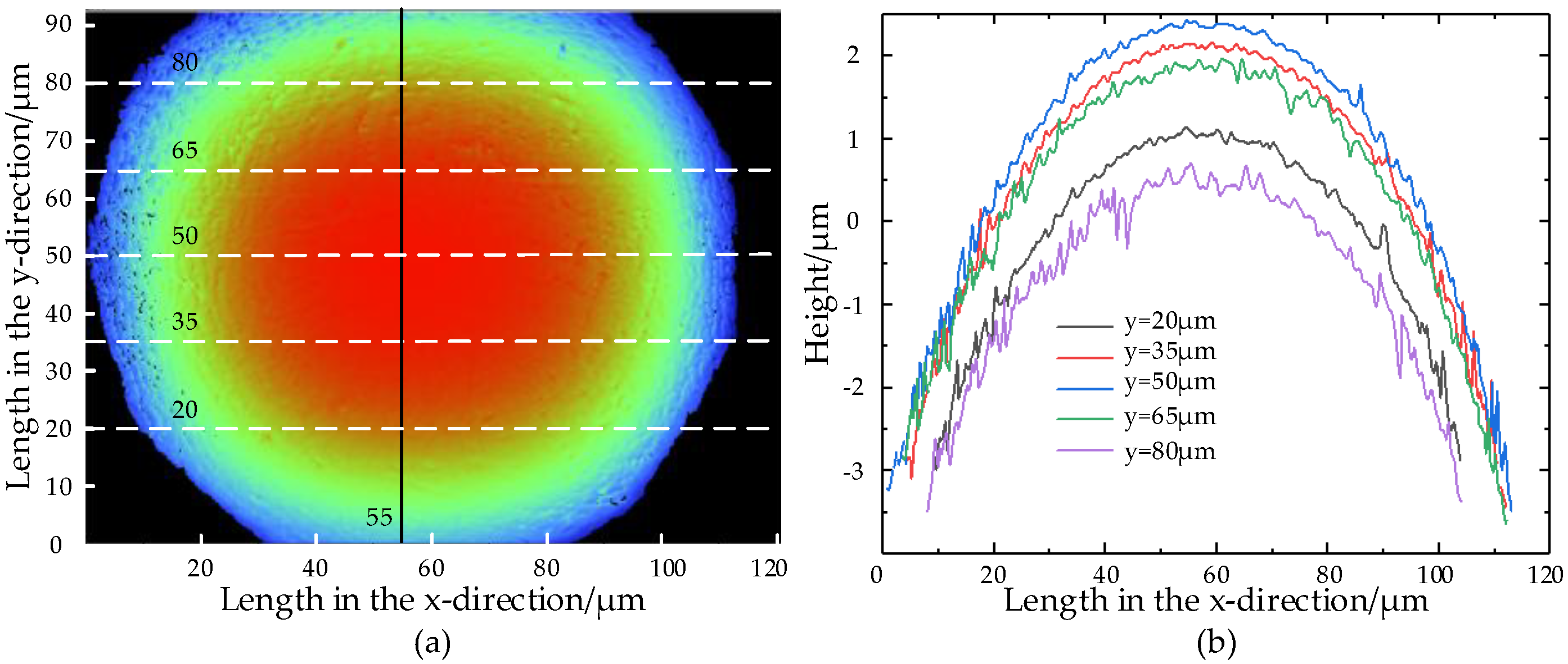
Figure 14 presents the surface topography of the microlens characterized using a 50× white-light interferometer. The diameter of this microlens is 100 μm approximately, and the height variation from the center to the edge is 4 μm approximately. The radius of curvature in this microlens is 230 μm.
As shown in Figure 15, height profiles were extracted at x = 55 μm along five parallel lines corresponding to y = 20 μm, 35 μm, 50 μm, 65 μm, and 80 μm, respectively. The measured height differences for these profiles are 2.96 μm, 3.90 μm, 5.23 μm, 3.92 μm, and 2.90 μm, exhibiting a clear symmetrical distribution. Both morphological characteristics and quantitative data confirm that the circular microlens possesses a well-defined structure. This method is feasible for preparing a circular microlens.
For the microlens presented in Figure 15, the measured radius of curvature in the x-direction and y-direction is 270 μm and 280 μm, respectively, demonstrating high geometrical consistency. The focal length calculation formula can be queried to calculate the focal length of the microlenses.
In the fabrication of MLAs, the shape of the mask aperture critically influences the resulting surface morphology of the microlenses. When a mask with predominantly parabolic boundaries is employed, the high linearity of such contours often results in inadequate curvature formation at the top region, as evidenced in Figure 16. Therefore, mask designs incorporating highly nonlinear boundary shapes are recommended to achieve improved lens topography.
In the fabrication of MLAs, the geometry of the exposure mask determines the morphology of the microlens directly. When employing a mask design with predominantly parabolic boundaries, the high linearity of these contours tends to generate sharp peaks rather than smooth curvatures at the lens apex, as demonstrated in Figure 16. Therefore, the white-light interferometer cannot characterize its surface profile fully. During the experimental process, progressively enhanced nonlinear boundary designs (mask-3 to mask-5) yield gradually improved curvature formation at the lens apex. Therefore, mask configurations incorporating highly nonlinear boundaries are recommended to achieve superior microlens topography.
The use of a parabolic mask in conjunction with motion etching enables the fabrication of microstructures with different heights between the center and edge. However, the resulting profiles typically exhibit non-smooth transitions, making them unsuitable for conventional MLA preparation. On the other hand, the parabolic mask design offers a valuable conceptual approach for developing a specialized microlens, thereby broadening the scope of custom optical components to suit diverse application requirements.

3.4. Morphology of MLA

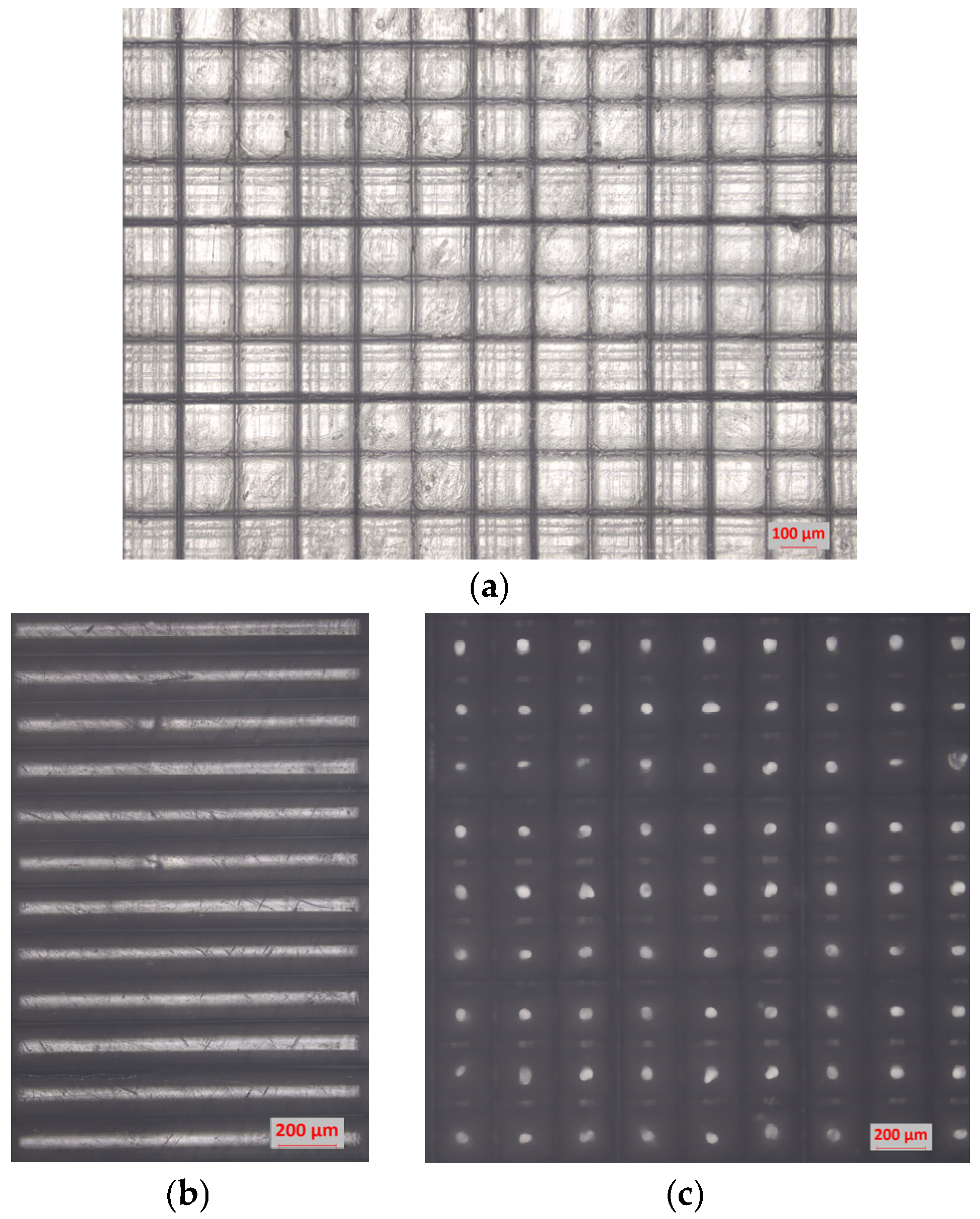
Figure 17 displays optical micrographs of circular MLAs and cylindrical MLAs under 5× magnification. A distinct variation in light transmittance is observed across the processed regions, with the central area of each microlens exhibiting noticeably stronger transmission relative to its periphery.
The measurement results in 2D and 3D show that the excimer laser motion mask method can be used to prepare MLAs.

4. Conclusions

This study demonstrates the use of the excimer laser motion mask method to fabricate MLAs on PMMA substrates. The working principle regarding a specific exposure motion mask was thoroughly analyzed, establishing that spatially varying cumulative exposure leads to corresponding differences in material removal depth.
A transient 3D model was established to simulate the dynamic process of microlens formation on PMMA via the excimer laser motion mask technique. This model effectively illustrates the morphological evolution from the initial substrate to the final microlens structure, providing enhanced visualization of the fabrication dynamics. The simulation framework enables systematic analysis of the manufacturing process, thereby facilitating process optimization and reducing experimental costs associated with parameter screening. Furthermore, the model can be extended to stress−strain analysis during fabrication, which contributes to the reduction in processing defects and improvement of product longevity.
Cylindrical and circular MLAs were fabricated successfully by motion mask etching experiments. Characterization results confirm the structure of these two types MLAs are integral. The height difference, span, and surface roughness are 7.08 μm, 90 μm, and 90 nm in these cylindrical convex MLAs. For circular convex MLAs, the arc height difference, diameter, and radius of curvature are 4.0 μm, 100 μm, and 230 μm. Laser polishing, as a non-contact polishing technology, could be used in subsequent studies to enhance the surface quality of MLAs.
The excimer laser motion mask method offers a straightforward and efficient process for MLA fabrication, eliminating the need for chemical reagents and demonstrating strong potential in applications with optical instruments. Furthermore, this technique can fabricate MLAs to achieve different applications by designing specific exposure masks, which provide considerable flexibility and adaptability in practice.

Author Contributions

Conceptualization, T.C.; methodology, T.C. and L.W.; validation, L.W.; formal analysis, L.W.; investigation, L.W.; resources, T.C.; data curation, L.W.; writing—original draft preparation, L.W.; writing—review and editing, T.C.; visualization, L.W.; supervision, T.C.; project administration, T.C.; funding acquisition, T.C. All authors have read and agreed to the published version of the manuscript.

Funding

This research was funded by Beijing Natural Science Foundation—Huairou Innovation Joint Fund Project, grant number L245012.

Data Availability Statement

Data will be made available on request.

Acknowledgments

Thanks to Excimer Laser Micro Technology Lab.

Conflicts of Interest

The authors declare no conflicts of interest.

Abbreviations

The following abbreviations are used in this manuscript:
MLAMicrolens Array
PMMAPolymethylmethacrylate
2DTwo-Dimensional
3DThree-Dimensional

References

  1. Gu, Z.X.; Zeng, L. Tunable Imaging and Simulation Based on Microlens Array. Acta Photonica Sin. 2025, 54, 0211003. [Google Scholar]
  2. Zhong, Y.; Yu, H.B. Novel Optofluidic Imaging System Integrated with Tunable Microlens Arrays. ACS Appl. Mater. Interfaces 2023, 15, 11994–12004. [Google Scholar] [CrossRef] [PubMed]
  3. Wu, G.X.; Ng, S.W.L. Dynamic nano-imaging via a microsphere compound lens integrated microfluidic device with a 10× objective lens. Lab. Chip 2023, 23, 3070–3079. [Google Scholar] [CrossRef] [PubMed]
  4. Zheng, Y.J.; Bian, Q. Technical Study of Microlens Arrays for Gaussian Beam Homogenization Shaping. Chin. J. Lasers 2025, 52, 0105002. [Google Scholar]
  5. Hou, Z.J.; Wang, X.D. Preparation and Performance of Integration Device between Si Microlens Array and Infrared Focal Plane Array (Invited). Acta Photonica Sinica 2024, 53, 0753304. [Google Scholar]
  6. Huang, S.Q.; Song, Z.Y. Rapid fabrication and characteristics analysis of high-filling-factor microlens array. Infrared Laser Eng. 2021, 50, 329–333. [Google Scholar]
  7. Shao, J.Z.; Liang, X. Excimer laser marking—A precise patterning technique for material surfaces. Opt. Laser Technol. 2024, 176, 110974. [Google Scholar] [CrossRef]
  8. Qin, D.; Guo, J. Surface Characterization and Tribology Behavior of PMMA Processed by Excimer Laser. Chin. J. Mech. Emg. 2023, 36, 60–76. [Google Scholar] [CrossRef]
  9. Kong, D.J.; Sun, X.Y. Superhydrophobic quasi-periodic concave microlens array on fused silica prepared by spatially modulated picosecond laser parallel processing. Ceram. Int. 2024, 50, 42922–42932. [Google Scholar] [CrossRef]
  10. Ottevaere, H.; Cox, R. Comparing glass and plastic refractive microlenses fabricated with different technologies. J. Opt. A Pure Appl. Op. 2006, 8, 407–429. [Google Scholar] [CrossRef]
  11. Liu, X.; Yu, L. Optical Nanofabrication of Concave Microlens Arrays. Laser Photonics Rev. 2019, 13, 1800272. [Google Scholar] [CrossRef]
  12. Zhang, Z.X.; Lei, H.Q. Fabrication of high-quality microlens arrays on fused silica based on combined rapid evaporative ablation and precision melting polishing of CO2 lasers. J. Mater. Res. Technol. 2024, 33, 3928–3943. [Google Scholar] [CrossRef]
  13. Li, Q.K.; Liu, X.Q. Fabrication of glass microlens arrays by laser-based technology. Laser Technol. 2021, 45, 131–136. [Google Scholar]
  14. Zolfaghari, A.; Zhang, L. Replication of plastic microlens arrays using electroforming and precision compression molding. Microelectron. Eng. 2021, 239–240, 111529. [Google Scholar] [CrossRef]
  15. Yi, J.H.; Baek, C.H. Fabrication of a light screen-aperture integrated flexible thin film micro-lens array for a biomimetic superposition compound eye. Opt. Express 2021, 29, 39214–39226. [Google Scholar] [CrossRef] [PubMed]
  16. An, H.; Qian, Y.F. Unveiling the effects of laser scanning direction and processing parameters on heat transfer and ablation behavior of CFRP. Compos. Part. B Eng. 2025, 298, 112407. [Google Scholar] [CrossRef]
  17. Xing, H.X.; Wang, S. Gold film suppresses ablation damage of CVD polycrystalline diamond by sub-nanosecond pulsed laser processing: Experimental and theoretical investigation. Diam. Relat. Mater. 2025, 153, 112100. [Google Scholar] [CrossRef]
  18. Zhao, J.G.; Han, X. Innovative multiscale simulation with experimental validation of ultrafast laser processing in silicon carbide (4H-SiC). J. Manuf. Process. 2025, 137, 252–262. [Google Scholar] [CrossRef]
  19. Liu, Y.; Ouyang, P.F. Multi-energy field simulation and experimental research on backside water assisted laser processing for thin-walled irregular metal micro-holes. Opt. Laser Technol. 2025, 187, 112790. [Google Scholar] [CrossRef]
  20. Lin, Z.J.; Ji, L.F. Surface defects state analysis of laser induced graphene from 4H-SiC. J. Mater. Res. Technol. 2020, 9, 5934–5941. [Google Scholar] [CrossRef]
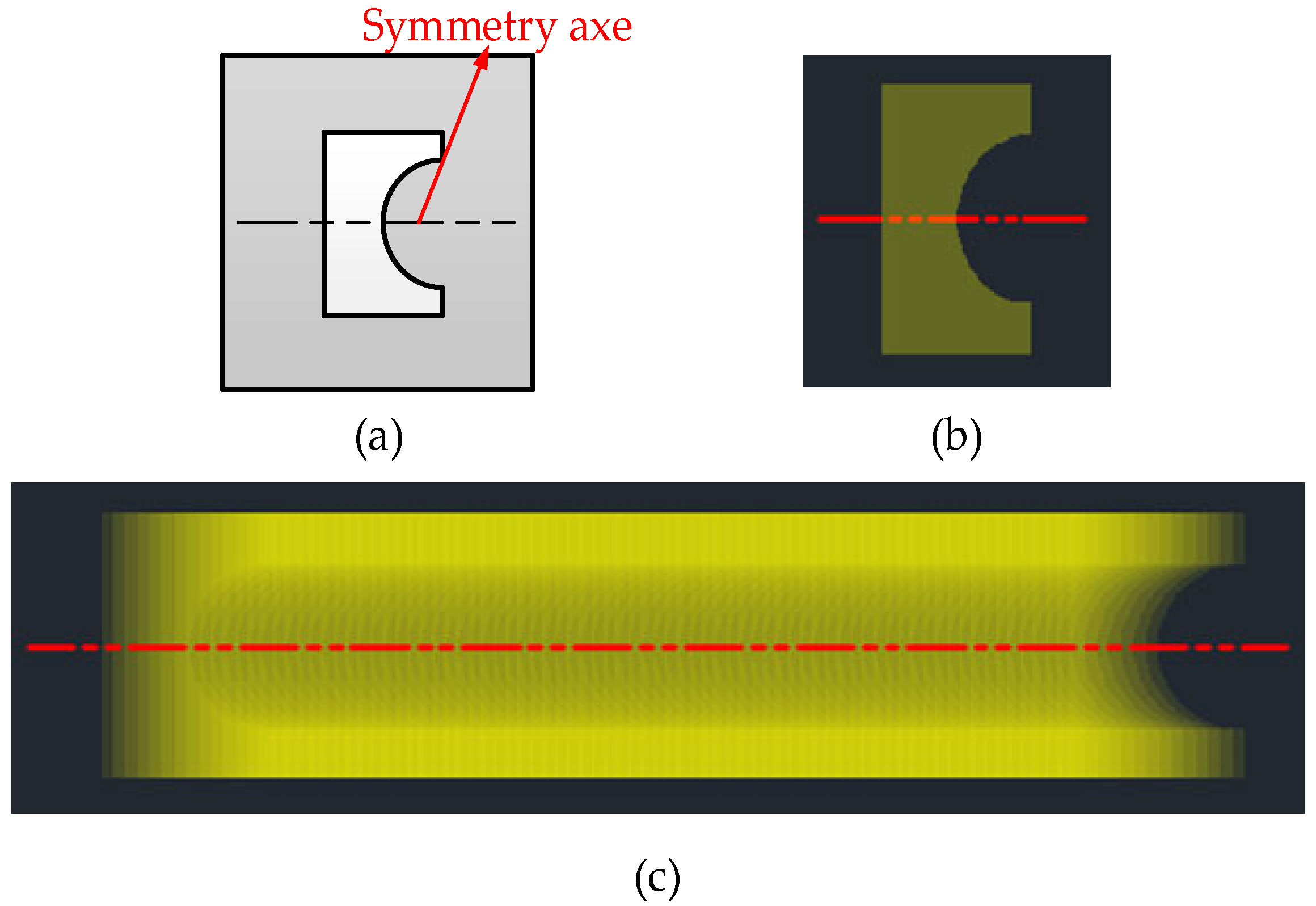
Figure 1. Specific exposure mask and etching. (a) The shape of specific exposure mask. (b) Etching of single pulse. (c) Etching of multi-pulse.
Applsci 15 10664 g001
Figure 2. The principle of preparation of MLA. (a) Scanning etching in direction 1. (b) Scanning etching in direction 2. (c) Model of MLA.
Applsci 15 10664 g002
Figure 3. Preparation process of MLA.
Applsci 15 10664 g003
Figure 4. Mathematical model of scanning etching.
Applsci 15 10664 g004
Figure 5. Energy distribution of laser’s specific irradiation.
Applsci 15 10664 g005
Figure 6. Results of numerical calculation.
Applsci 15 10664 g006
Figure 7. Etching morphology changes on plane y−z and x−z.
Applsci 15 10664 g007
Figure 8. Experimental system of preparing MLAs.
Applsci 15 10664 g008
Figure 9. Perfection of specific exposure mask. (a) Model of mask. (b) Entity of mask-1. (c) Entity of mask-2.
Applsci 15 10664 g009
Figure 10. Single-pulse fixed-point etching results.
Applsci 15 10664 g010
Figure 11. Multi-pulse motion etching. (a) Motion etching about two pulses. (b) Motion etching of three pulses.
Applsci 15 10664 g011
Figure 12. Measurement results of cylindrical microlens. (a) 3D of cylindrical microlenses. (b) Height variations at different positions on cylindrical microlens.
Applsci 15 10664 g012aApplsci 15 10664 g012b
Figure 13. Measurement results of cylindrical microlens. (a) Location of extracted data. (b) Curve of height data.
Applsci 15 10664 g013
Figure 14. Measurement results of circular microlens. (a) 3D of circular microlens. (b) Height difference in x-direction. (c) Height difference in y-direction.
Applsci 15 10664 g014
Figure 15. Measurement results of circular microlens. (a) Location of extracted data. (b) Curve of height data.
Applsci 15 10664 g015
Figure 16. The mask affects the forming morphology of the microlens. (a) Three types of parabolic masks. (b) Results of measurement.
Applsci 15 10664 g016
Figure 17. Morphologies of MLAs. (a) Circular MLAs by mask-1. (b) Cylindrical MLAs by mask-2. (c) Circular MLAs by mask-2.
Applsci 15 10664 g017
Table 1. Information on PMMA materials.
EntryMaterialAttribute
IndexPMMADensityHeat capacityThermal conductivity
Parameter(C5O2H8)n1190 kg/m31420 J/(kg·K)0.2 W/(m·K)
Table 2. Information on excimer laser loading.
EntryLaser Irradiation Parameters
IndexWavelengthEnergyPulse widthFrequencyScanning speed
Parameter248 nm720 mJ30 ns25 Hz0.02 mm/s
Table 3. Information of specific exposure mask and etching morphology.
TypeMaskFocusing Objective LensEtching Morphology
IndexLengthWidthMagnificationLengthWidth
Parameter11.6 mm3 mm0.053×605 μm158 μm
6.5 mm1.6 mm0.053×346 μm84 μm
Disclaimer/Publisher’s Note: The statements, opinions and data contained in all publications are solely those of the individual author(s) and contributor(s) and not of MDPI and/or the editor(s). MDPI and/or the editor(s) disclaim responsibility for any injury to people or property resulting from any ideas, methods, instructions or products referred to in the content.