Article

Influence of Bedding Angle on Mechanical Behavior and Grouting Reinforcement in Argillaceous Slate: Insights from Laboratory Tests and Field Experiments

1
Hunan Engineering Research Center of Structural Safety and Disaster Prevention for Urban Underground Infrastructure, Hunan City University, Yiyang 413000, China
2
School of Civil Engineering, Guizhou University, Guiyang 550025, China
3
School of Geosciences and Info-Physics, Central South University, Changsha 410083, China
*
Author to whom correspondence should be addressed.
Appl. Sci. 2025, 15(19), 10415; https://doi.org/10.3390/app151910415
Submission received: 25 July 2025 / Revised: 23 September 2025 / Accepted: 23 September 2025 / Published: 25 September 2025
(This article belongs to the Special Issue Advances in Slope Stability and Rock Fracture Mechanisms)

Abstract

Argillaceous slate (AS) is a typical metamorphic rock with well-developed bedding, widely distributed globally. Its bedding structure significantly impacts slope stability assessment, and the challenges associated with slope anchoring and support arising from bedding characteristics have become a focal point in the engineering field. In this study, with bedding dip angle as the key variable, mechanical tests such as uniaxial compression, triaxial compression, direct shear, and Brazilian splitting tests were conducted on AS. Additionally, field anchoring grouting diffusion tests on AS slopes were carried out. The aim is to investigate the basic mechanical properties of AS and the grout diffusion law under different bedding dip angles. The research results indicate that the bedding dip angle has a remarkable influence on the failure mode, stress–strain curve, and mechanical indices such as compressive strength and elastic modulus of AS specimens. The stress–strain curves in uniaxial and triaxial tests, as well as the stress-displacement curve in the Brazilian splitting test, all undergo four stages: crack closure, elastic deformation, crack propagation, and post-peak failure. As the bedding dip angle increases, the uniaxial and triaxial compressive strengths and elastic modulus first decrease and then increase, while the splitting tensile strength continuously decreases. The consistency of the bedding in AS causes the grout to diffuse in a near-circular pattern on the bedding plane centered around the borehole. Among the factors affecting the diffusion range of the grout, the bedding dip angle and grouting angle have a relatively minor impact, while the grouting pressure has a significant impact. A correct understanding and grasp of the anisotropic characteristics of AS and the anchoring grouting diffusion law are of great significance for slope stability assessment and anchoring design in AS areas.

1. Introduction

Argillaceous slate (AS), as a layered soft rock with significant anisotropy [1], is widely distributed in engineering geological environments worldwide and spans a large range of geological ages [2]. Given this characteristic, AS is also used as a marker for archeological excavations in archeological research [3]. China is one of the countries with the most extensive distribution of AS [4]. As a low-grade metamorphic rock, the mechanical behavior of AS is significantly influenced by its bedding structure [5,6]. Consequently, the field of structural geology has focused on the cleavage characteristics and formation mechanisms of slate [2,7]. Meanwhile, in the engineering field, AS has attracted considerable attention as a civil engineering material due to its platy cleavage properties [8,9,10]. For example, AS can be combined with other materials for use in building exterior walls and wall cladding [11].
However, due to its high content of clay minerals, AS exhibits characteristics such as poor water stability, susceptibility to weathering, softening, and disintegration, which give rise to a series of engineering problems. For instance, in the construction of tunnels, slopes, and other projects, the stability of AS has a direct impact on the safety and durability of the engineering works [12,13]. Particularly in the central and western regions of China, the complex geological conditions pose numerous challenges to AS engineering, including groundwater chemical erosion and high in situ stress [14]. For example, Zuo et al. [15,16] conducted research on the swelling characteristics of AS in water-rich environments, dividing its swelling process into three stages and confirming that microscale damage in AS drives the degradation of its macroscale mechanical properties. Additionally, studies on the mechanical properties of AS after water treatment have also demonstrated that changes in its pore structure lead to a significant decline in its physical and mechanical properties [17,18].
In recent years, with the continuous advancement of infrastructure construction, it is inevitable to encounter geological environments with AS during engineering projects. AS is generally classified as a low-grade metamorphic rock, formed through the metamorphism of muddy rocks such as shale. Existing research has confirmed that the bedding dip angle is one of the key factors influencing the mechanical properties of shale. Shale specimens with different bedding dip angles exhibit varying strength and deformation characteristics in uniaxial compression, triaxial compression, and other tests [19,20]. For example, when studying the bedding dip angle effects on layered hard rocks under triaxial stress paths, the influence of shale needs to be taken into account [21]. However, shale and argillaceous slate (AS) may demonstrate different characteristics in practical engineering scenarios [22,23]. In practical engineering scenarios, AS slopes are typically subjected to varying degrees of weathering due to the continuous impacts of construction activities and geological forces (such as tectonic stress and weathering). Among them, moderately and highly weathered AS slopes pose significant stability issues owing to the reduced rock mass integrity and weakened mechanical properties. Therefore, stability assessments and targeted engineering measures (e.g., anchoring and the installation of support structures) are required to ensure the long-term stability of these slopes. Furthermore, as a critical structural feature of layered rock masses, the bedding dip angle significantly alters the stress distribution and failure modes of rock masses. Zhang et al. [24] unveiled the nonlinear influence mechanism of bedding anisotropy on rock mass stability, demonstrating that the anisotropic strength characteristics resulting from bedding structures are the key factors triggering shaft instability. Consequently, systematically investigating the influence mechanism of the bedding dip angle on the mechanical behavior of moderately to highly weathered AS not only provides a theoretical basis for the quantitative stability assessment of geotechnical engineering projects but also offers crucial technical support for optimizing support structure parameters and formulating disaster prevention and control strategies, thereby possessing clear engineering application value and scientific significance.
In the fields of geotechnical engineering, such as slope engineering [25,26], tunnel excavation, and underground cavern construction, the presence of bedding planes often leads to significant anisotropic mechanical behavior in rock masses [27,28]. This behavior is specifically manifested by the pronounced directional dependence of mechanical parameters, including compressive strength, shear strength, and tensile strength, which can readily trigger geological disasters like landslides, rockfalls, or local instability [29]. In landslide research, AS plays a pivotal role. For instance, utilizing the extended Newmark sliding block model, studies can be conducted on the multi-sliding surface displacements of layered rock slopes under seismic action, encompassing rock masses such as phyllitic slate and shale [30]. Furthermore, the tectonic effects exert a non-negligible influence on the formation and characteristics of landslide dams. Particularly near fault zones, the presence of AS may affect the stability and evolutionary processes of landslide dams [31]. Therefore, an in-depth exploration of the failure characteristics of rocks under external forces holds particularly significant importance for the stability analysis of geotechnical engineering projects [32].
Grouting reinforcement, as a commonly used and effective technical approach in the field of geotechnical engineering [33], plays a pivotal role in improving the mechanical properties and enhancing the overall stability of AS [34,35]. Among them, grouted anchorage is a prevalent technique for improving the stability of layered rock masses [36]. However, the current diffusion pattern of grout within bedding planes and its interaction mechanism with bedding dip angles remain unclear, which, to some extent, restricts the optimization of grouting parameters. Additionally, factors such as the type of grouting material, grouting pressure, and grouting range all influence the reinforcement effect [37,38]. Cement-based grouting materials are widely applied in geotechnical reinforcement projects due to their excellent flowability and early strength development [39,40]. In practical engineering, the inherent structural characteristics of AS significantly constrain the grouting effect. For instance, the presence of bedding planes tends to induce non-uniform diffusion of grout along preferential pathways, thereby reducing the overall reinforcement efficiency [41,42]. To address this issue, this study focuses on moderately weathered AS as the research object and adopts a combined approach of laboratory and field experiments. Specifically, laboratory rock mechanical property tests are conducted on moderately weathered AS with varying bedding dip angles to clarify the influence patterns of bedding dip angle variations on the mechanical parameters and failure modes of AS. Furthermore, considering the bedding characteristics and the effect of high-pressure secondary grouting, the anchoring grout is forced into the interlayers of the AS, forming non-standard cylindrical irregular anchored solids together with the anchor bolts and surrounding rock. However, the diffusion pattern of grout within layered rock masses remains unclear at present.
To systematically investigate the impacts of slope rock dip angle, grouting pressure, and grouting angle on grout diffusion, this study carries out field borehole grouting tests based on a highway slope engineering project and performs statistical analyses on the diffusion range and reinforcement zone characteristics of the grout under specified conditions. Through the aforementioned research, this study delves into the influence mechanism of bedding dip angle on the mechanical behavior of AS and elucidates the diffusion pattern of grout within AS. The research findings provide theoretical foundations and technical support for slope reinforcement projects under similar geological conditions, thereby ensuring the safety and long-term stability of the engineering works.

2. Experimental Materials and Methods

2.1. Rock Specimens and Laboratory Testing Methods

The argillaceous slate (AS) used in the experiment was sourced from the construction site of Binjiang New City Project (Changsha, China). The AS exhibits a highly pronounced water-softening characteristic and is classified as a vulnerable rock mass, making it extremely challenging to drill natural AS samples with specific shapes. Therefore, cylindrical specimens were obtained by drilling cores with a diameter of 50 mm from the in situ rock at the project site at bedding dip angles of 0°, 30°, 60°, and 90°, as illustrated in Figure 1a. Subsequently, these cores were precisely machined into cylindrical specimens with a height of 100 mm through cutting and grinding processes, in accordance with the “Test Regulations for Rock in Water Resources and Hydropower Engineering” (Chinese standard SL/T 264-2020 [43]) and the standards recommended by the International Society for Rock Mechanics (ISRM). The finished cylindrical specimens are shown in Figure 1a. Disk specimens were prepared from the finished cylindrical specimens by cutting and grinding, following the method depicted in Figure 1b. Cylindrical disk specimens (50 mm in diameter × 25 mm in height) were prepared for Brazilian tensile strength tests and direct shear tests. The completed disk specimens are presented in Figure 1b. Mechanical property tests on specimens were all carried out under dry conditions.
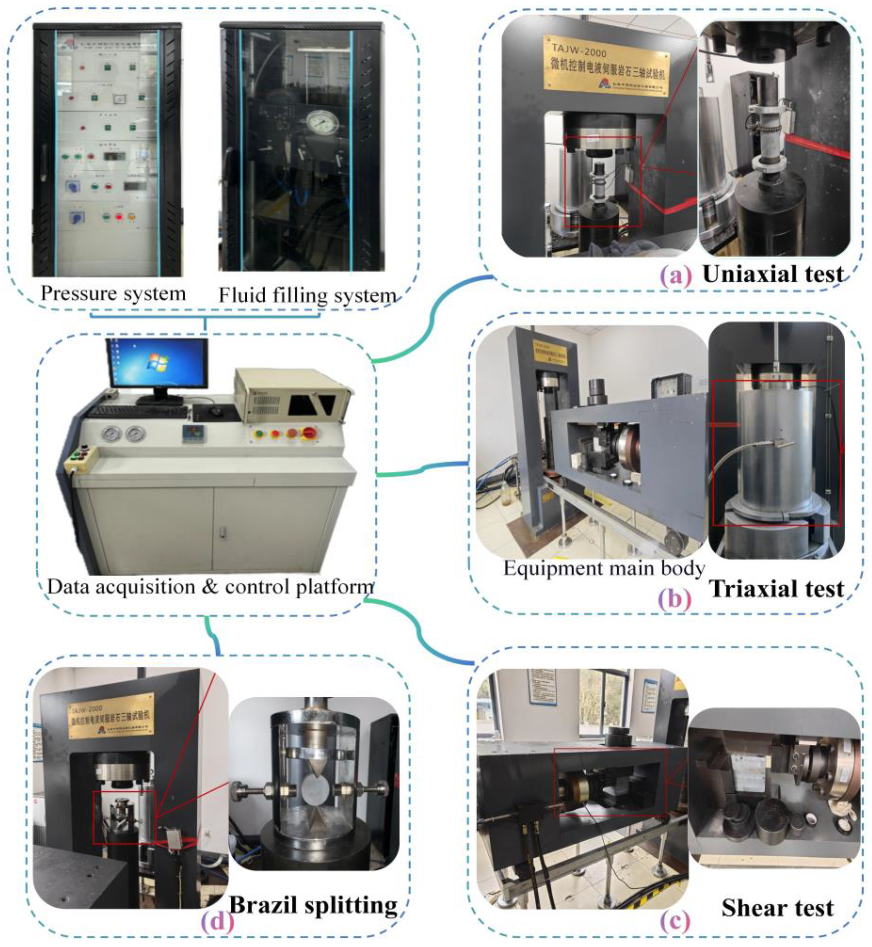
The TAJW-2000 microcomputer-controlled electro-hydraulic servo rock triaxial testing machine, manufactured by Changchun Chaoyang Experimental Instrument Company (Changchun, China), was employed in this study. The testing machine setup is illustrated in Figure 2. This apparatus was utilized to conduct uniaxial compression tests, triaxial compression tests, direct shear tests, and Brazilian splitting tests on rock specimens. For the uniaxial compression test, the uniaxial compression system of the testing machine (Figure 2a) was used. The loading process was controlled by displacement, with a loading rate of 0.2 mm/min. The triaxial compression test was carried out using the triaxial compression system of the testing machine (Figure 2b). The confining pressures were set at 0 MPa, 5 MPa, and 10 MPa, respectively, with a confining pressure loading rate of 2 MPa/min. The axial load in the triaxial test was also displacement-controlled, with a loading rate of 0.02 mm/min. The uniaxial and triaxial compression test methods were carried out in accordance with the procedures and requirements of ASTM D7012-14 [44]. During the direct shear test, the normal load must be maintained at a constant level. The shear load is applied in 10 to 12 stages. After each stage of load application, the shear displacement and normal displacement are recorded immediately, and then measured again after 5 min. When a significant increase in shear displacement is observed, the load increment between stages should be appropriately reduced. It is essential to ensure that at least 10 stages of shear loads are applied before reaching the peak value. The weakly weathered muddy slate rock samples collected in this study exhibit relatively high uniaxial and triaxial compressive strengths. Therefore, in accordance with the rock testing code, the preset normal stress in the direct shear test starts from 0.5 MPa and is increased in increments of 0.5 MPa up to a maximum of 3 MPa. The tensile strength test of the rock was performed through Brazilian splitting tests in compliance with ASTM D3967-16 [45]. The axial compression system of the testing machine was used for this test. The axial load was displacement-controlled, with a loading rate of 0.02 mm/min. The loading process of the rock specimen during the test is shown in Figure 2d.

2.2. Field Grouting Trial: Materials and Experimental Protocol

To clarify the impacts of factors such as rock stratum dip angle, grouting pressure, and grouting angle on the diffusion of grout in the study area, a field investigation of the project was first carried out. An argillaceous slate slope with well-developed bedding planes and significant fluctuations in rock stratum dip angles was selected as the test site. Field drilling and grouting tests were conducted on this AS slope, and the diffusion range and reinforcement area of the grout under specified conditions were statistically analyzed. The cement used in the tests was commercial cement (produced by Hunan Yiyang Shaofeng Cement Co., Ltd., China). The type and strength grade of the cement were P.O 42.5, and the water-solid ratio of the cement grout was 0.5. During the tests, down-the-hole drilling was employed for hole formation, and a grouting pump with adjustable pressure was used for grouting. After grouting was completed, the grout was allowed to solidify, and then the crushed stones were excavated and removed to facilitate the measurement of the grout diffusion range. The specific test procedure is shown in Figure 3.
In engineering experimental research, complex interactions among multiple factors with multiple levels are commonly encountered. Given the constraints of on-site experimental conditions, this study adopts the orthogonal experimental design method. Statistical analysis of the experimental results is conducted using methods such as range analysis and analysis of variance. The experiment takes into account the influence of the bedding dip angle of AS, grouting pressure, and borehole dip angle (grouting angle) on grout diffusion. Based on the on-site geological conditions and the Slope Anchorage Code (GB 50330-2013 [46], a Chinese standard), four levels are selected for each factor: 0°, 6°, 16°, and 30° for the bedding dip angle; 0.5 MPa, 1.0 MPa, 1.5 MPa, and 2.0 MPa for the grouting pressure; and 15°, 25°, 35°, and 45° for the borehole dip angle. An orthogonal experiment is designed accordingly, and the factor-level table is presented in Table 1. When there are three factors, each with four levels, the L16 (45) orthogonal table is typically employed. Since this experiment involves only three factors, this table can be utilized, with the remaining two columns regarded as blank columns. Surveying and staking-out are carried out according to the actual on-site situation. The positions of each borehole are arranged with a horizontal spacing of 1.5 m and a vertical height of 1.5 m in compliance with the requirements of the orthogonal experiment.

3. Results and Discussion

3.1. Uniaxial Compression Test Results and Analysis

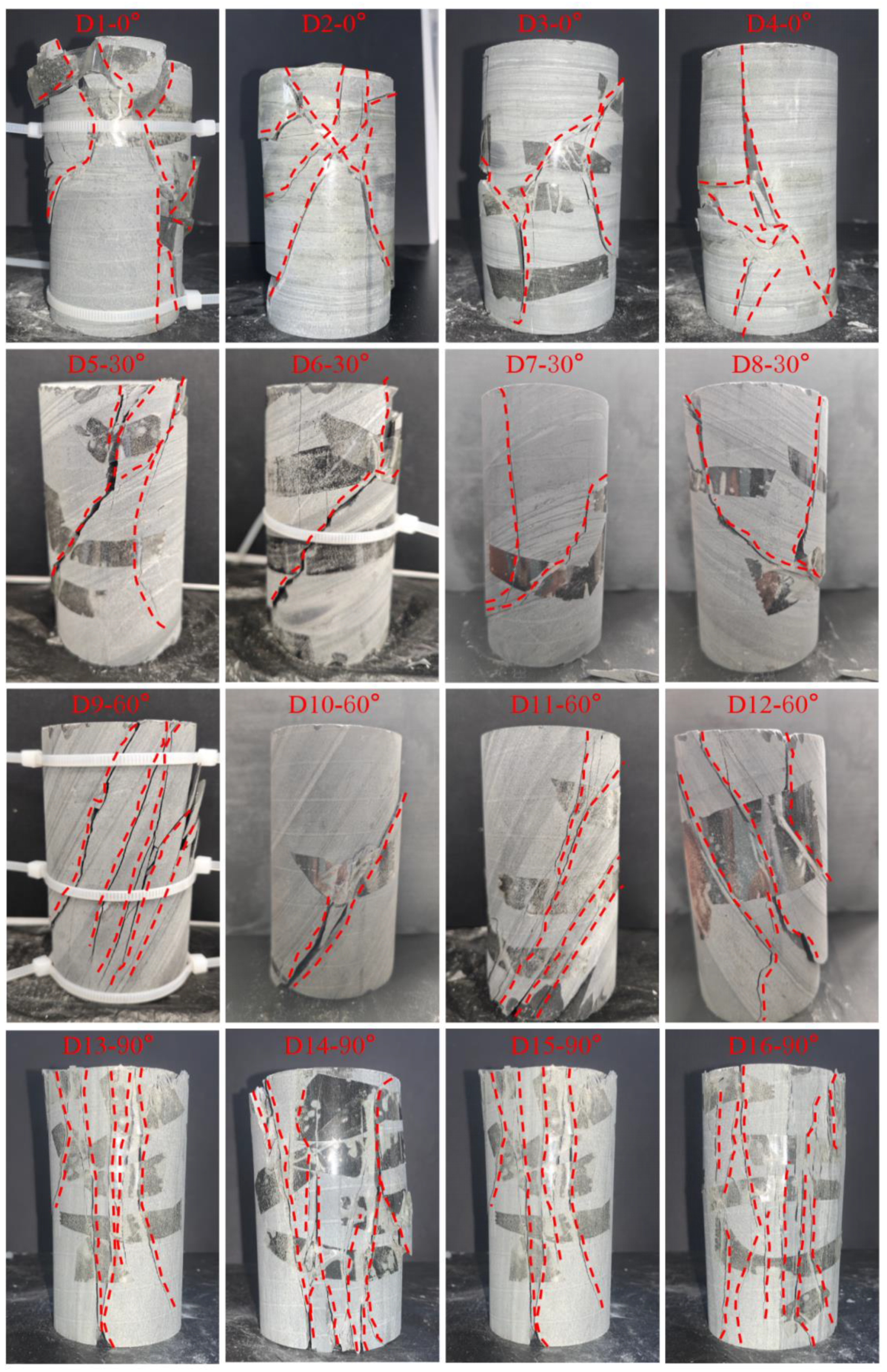
Uniaxial compression tests can be employed to observe the failure characteristics of AS. For each bedding dip angle (0°, 30°, 60°, and 90°), repetitive tests on four specimens are conducted. The failure characteristics of AS specimens under uniaxial compression tests for each bedding dip angle are presented in Figure 4. The rock failure modes mainly manifest as splitting tensile failure, shear-slip failure, ductile failure, and compound failure, among others. The specific failure mode is primarily influenced by the internal structure, fractures, and bedding characteristics of the rock. As shown in Figure 4, the rock specimens with bedding dip angles of 0° and 30° mainly undergo splitting tensile failure that traverses the bedding planes, accompanied by local shear failure. The specimens with a bedding dip angle of 60° predominantly exhibit shear-slip failure, while those with a bedding dip angle of 90° mainly experience splitting tensile failure. Moreover, the failure structural planes in both cases basically occur along the bedding planes, indicating that bedding has a significant impact on the failure mode of AS.
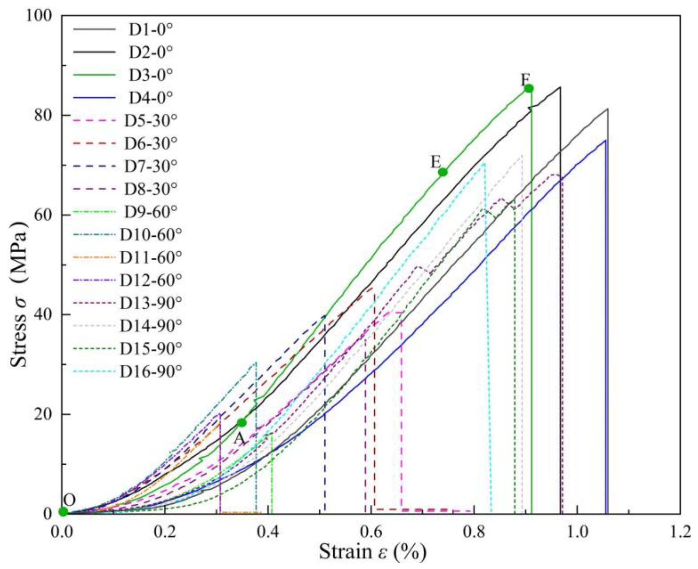
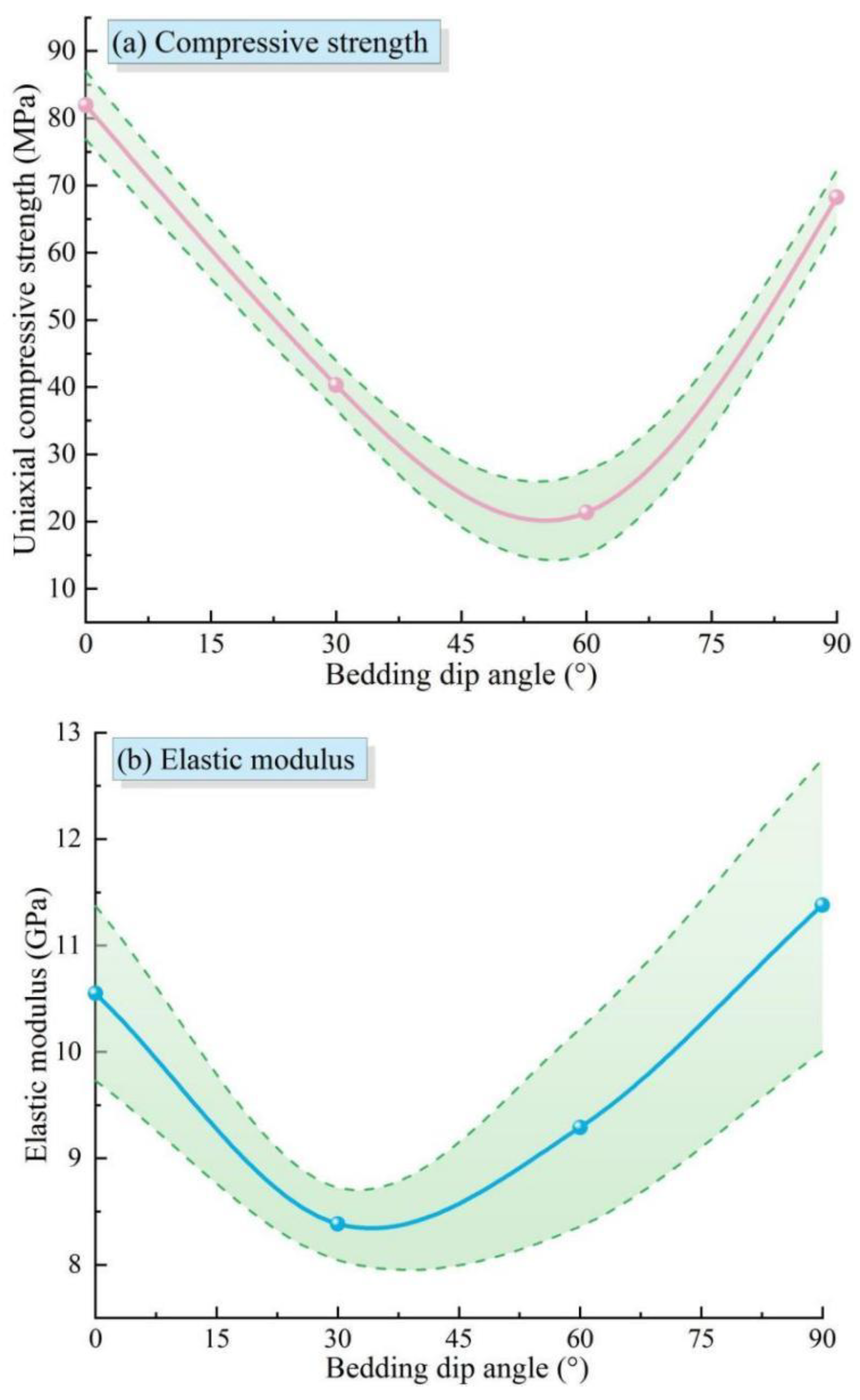
Based on uniaxial compression tests, by measuring the longitudinal and circumferential dimensional changes of rock specimens, the uniaxial compression stress–strain curves of AS at different bedding dip angles can be obtained (as shown in Figure 5). Combining these curves with the failure loads, key mechanical parameters such as the uniaxial compressive strength and elastic modulus of the AS can be calculated. The average values of these results are then plotted to illustrate the variation patterns of the uniaxial compressive strength and elastic modulus of AS with respect to the bedding dip angle, as depicted in Figure 6, where error bands are also provided.
Figure 5 reveals that the stress–strain curves of rock specimens in each group can be categorized into four typical stages: the crack-closure stage, the elastic-deformation stage, the crack-propagation stage, and the post-peak failure stage. Taking the uniaxial compression stress–strain curve of argillaceous slate with a bedding dip angle of 0° (D3-0°) as an example, during the initial loading phase from the origin Point O) to Point A, the OA segment exhibits rapid strain increase with relatively slow stress growth, showing an upward concave trend. This is attributed to the closure of internal defects, bedding planes, and micro-fissures under external forces, a stage commonly termed the crack closure or cumulative compaction phase. As the load continues to increase, the mechanical response curve transitions into the AE segment, developing an approximately linear morphology. This indicates that under load, micro-cracks and defects in the AS have been compressed and closed, leading the rock to behave as a near-dense medium. In this phase, stress and strain follow Hooke’s law, known as the elastic deformation stage. With sustained loading, the mechanical response curve in the EF segment exhibits convex linear development, where coupled elastic-plastic deformation occurs as the rock’s deformation exceeds its elastic limit, resulting in plastic deformation. During this phase, internal micro-cracks begin to propagate and new cracks may form, leading to non-recoverable deformation upon unloading. Thus, the EF segment represents the elasto-plastic deformation stage, also called the crack propagation stage. After reaching the peak stress, the rock fails, and the curve shows stress drop and oscillation beyond Point F, where the stress at F corresponds to the uniaxial compressive strength of the rock. Beyond Point F, the stress rapidly decreases while the strain remains nearly constant, referred to as the post-peak failure stage. The stress–strain curve also reveals that the peak stress of argillaceous slate initially decreases and then increases with increasing bedding dip angle. The minimum peak stress occurs at a dip angle of 60°, while the maximum is observed at 0°, demonstrating distinct anisotropic characteristics in the peak stress of argillaceous slate.
As shown in Figure 6, the overall uniaxial compressive strength and elastic modulus of the rock specimens change accordingly with different bedding dip angles. The uniaxial compressive strength reaches its maximum value when the bedding dip angle is 0° and its minimum value at 60° (Figure 6a). The elastic modulus is the highest when the bedding dip angle is 90° and the lowest at 30° (Figure 6b). The experimental results reveal the anisotropic variation pattern of the strength of AS along the bedding dip angle. Specifically, the strength of AS shows a U-shaped variation trend with the change in the bedding angle, reaching its maximum values at 0°or 90° and being the lowest in the range of 45–75°.

3.2. Triaxial Compression Test Results and Analysis

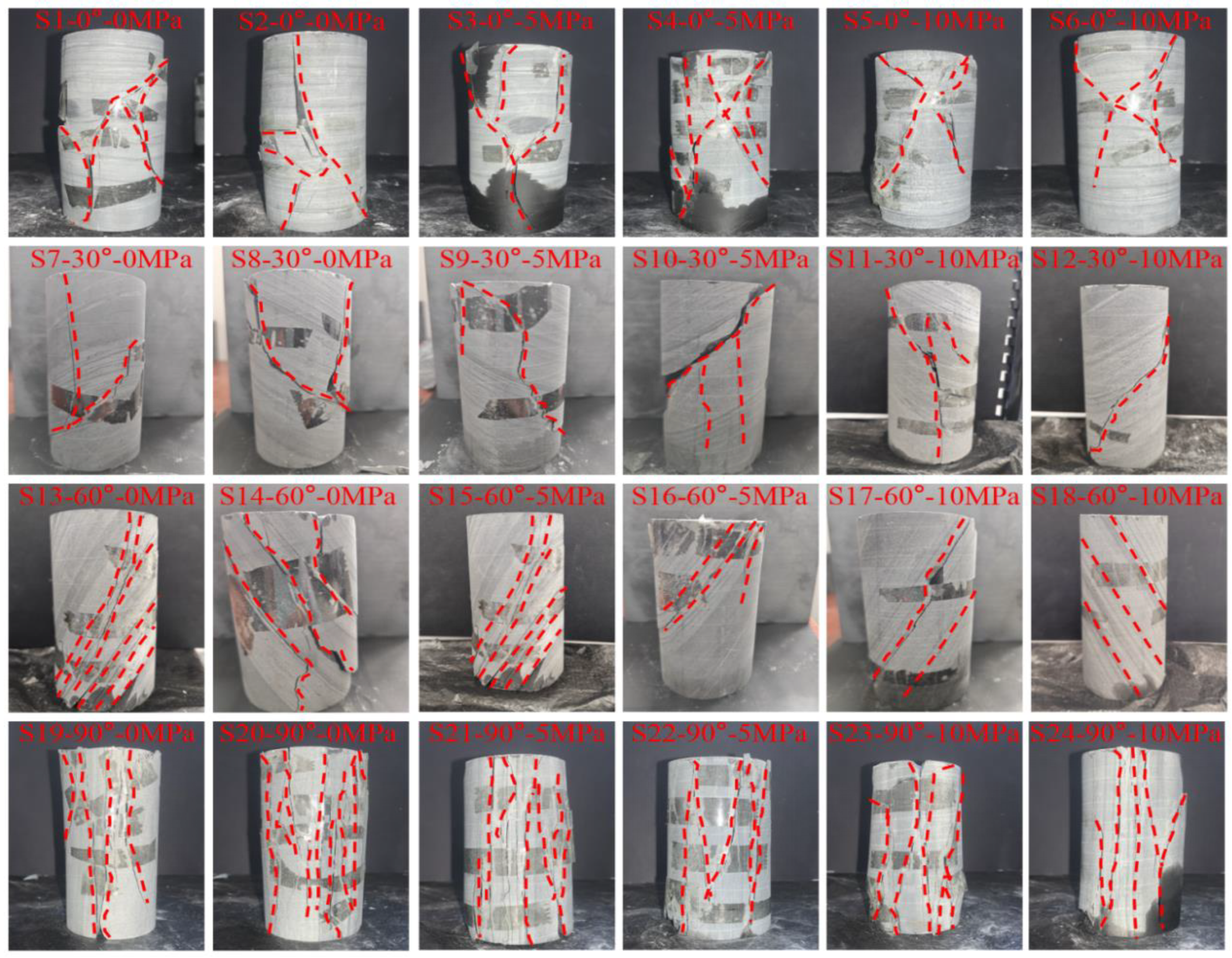
Triaxial compression tests were conducted on AS specimens under confining pressures of 0 MPa, 5 MPa, and 10 MPa. For each confining pressure level, two parallel tests were carried out. The failure and fracture characteristics of the rock specimens under triaxial compression at different bedding dip angles were obtained (Figure 7).
As shown in Figure 7, when the confining pressure increases, the failure mode of rock specimens with bedding dip angles of 0° and 30° transforms from a single splitting-tensile failure to a compound failure mode combining splitting-tensile and shear-slip failures. This change in failure is attributed to the fact that under low-angle bedding dip conditions, the load is mainly carried by the rock matrix and the normal direction of the bedding planes, resulting in relatively low tangential stresses and triggering a compaction-densification effect on the bedding planes, which subsequently induces crushing failure in local areas of the specimens. As the confining pressure further increases, cracks initiate at both ends of the specimens. These cracks gradually propagate and converge at the bedding planes, eventually extending towards the center of the specimens and running through them entirely. For specimens with a bedding dip angle of 60°, shear-slip failure still occurs under the influence of confining pressure, and the failure structural planes generally develop along the bedding planes. This is because, in this case, the load is mainly concentrated on the bedding planes of the rock. When the tangential stress on the bedding planes exceeds their interlayer shear strength, shear-slip failure occurs along the bedding planes. At this time, the uniaxial compressive strength of the rock is primarily determined by the bedding strength, which also leads to the specimens exhibiting the minimum uniaxial and triaxial compressive strengths at a bedding dip angle of 60°. As the confining pressure increases, the failure mode of specimens with a bedding dip angle of 90° changes from a single splitting-tensile failure to a compound failure mode combining splitting-tensile and shear-slip failures. This change is due to the fact that the bedding planes, as internal discontinuities, are parallel to the loading direction, facilitating the propagation of vertical tensile cracks along the bedding planes. In addition, even though the dip angle of the shear plane in specimens with a bedding dip angle of 90° is close to that of the bedding planes, their uniaxial compressive strength is significantly higher than that of specimens with a dip angle of 60°. This is because the rock columns formed after the bedding planes crack still provide effective compressive support, maintaining a relatively high overall strength. This further indicates that the failure mode and strength of bedded AS are mainly determined by the rock bedding planes.
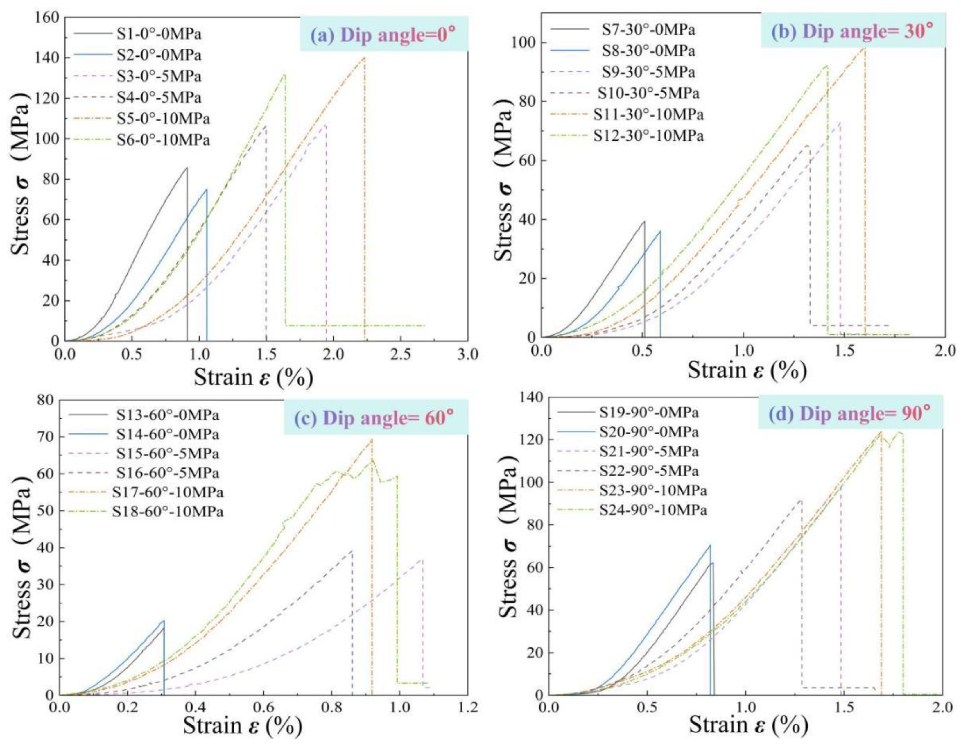
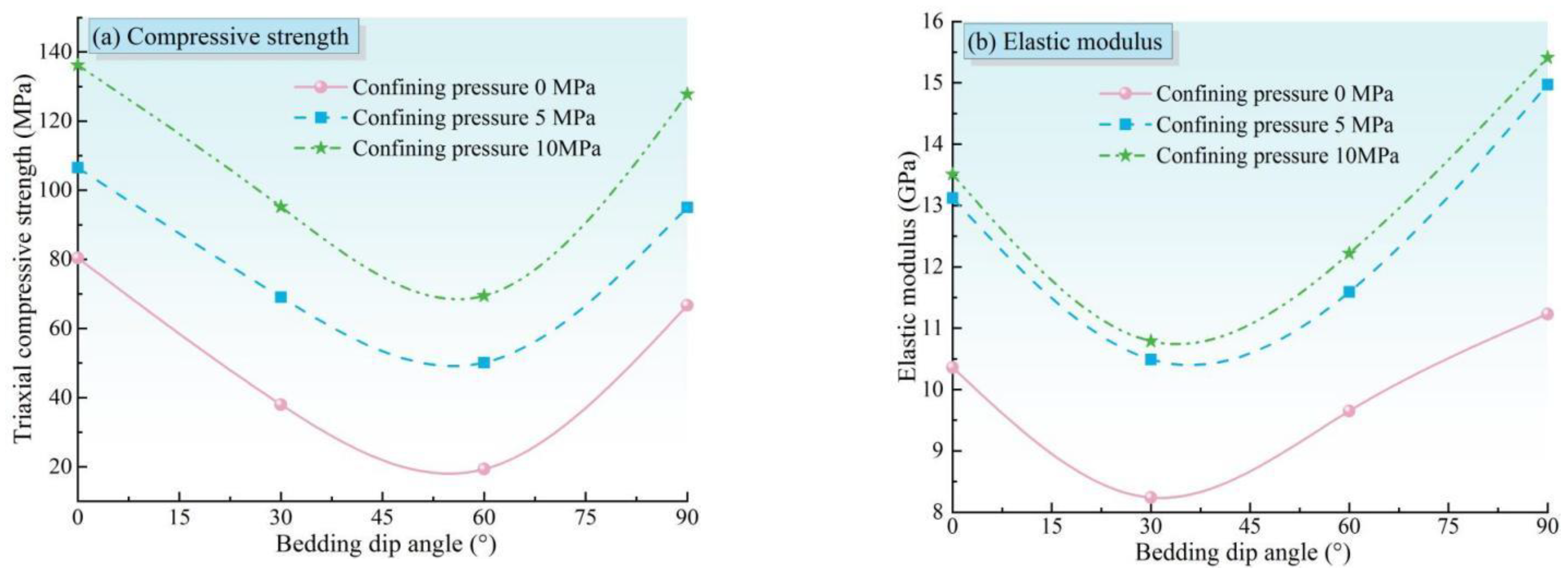
The triaxial compression test stress–strain curves of AS under different bedding dip angles were obtained from the triaxial compression tests (Figure 8). Based on Figure 8, the following observations can be summarized: The compaction stage of the rock specimens is relatively long. The crack closure stage shortens as the confining pressure increases, while the crack propagation stage is not prominent, and the plastic deformation in the pre-peak region is relatively small. The rock specimens undergo a relatively long linear elastic deformation stage before reaching the peak stress, with very little plastic deformation. This indicates that there is minimal internal damage in the specimens before failure, and most of the external forces are converted into elastic energy and stored within them. At the peak stress point, the stress–strain curve of the specimens drops sharply, and there is almost no plastic flow characteristic in the post-peak region, indicating that the specimens undergo typical brittle failure. During failure, the internal elastic potential energy is rapidly released, causing a cliff-like drop in stress. The confining pressure significantly affects the peak stress of the specimens. As the confining pressure increases, the failure stress rises. This is mainly attributed to the fact that the confining pressure enhances the compaction effect on the bedding planes, increases the normal stress on the bedding planes when bearing loads, leads to the rapid closure of cracks and fissures within the rock structure, and increases the sliding friction between cracks and fissures, thereby improving the peak strength of the rock. As the dip angle changes, the overall variation patterns of the compressive strength and elastic modulus of the specimens under triaxial compression tests are consistent with those under uniaxial compression tests (Figure 9).

3.3. Direct Shear Test Results and Analysis

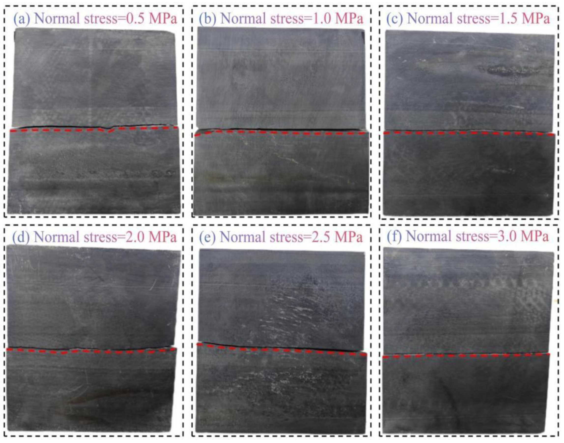
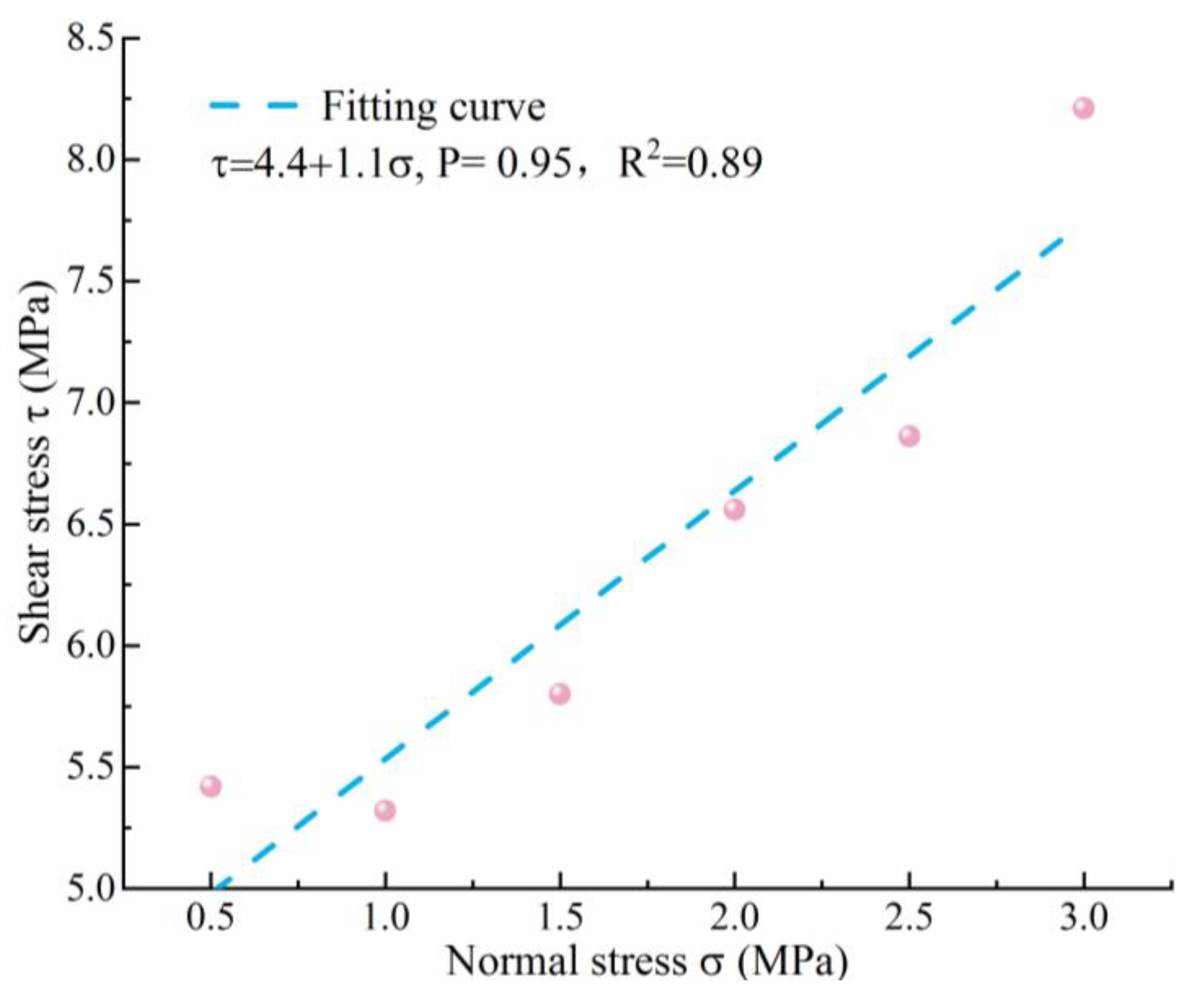
AS exhibits well-developed bedding, and the shear strength parameters of its bedding planes directly reflect the inherent strength and stability of the rock mass bedding planes. Rock specimens with developed bedding were selected for direct shear tests. Figure 10 shows the failure characteristics of each specimen under normal stresses ranging from 0.5 MPa to 3 MPa. Figure 10 indicates that the shear failure of the specimens mainly occurs on the bedding planes parallel to the loading direction, and the failure surfaces are relatively smooth. This phenomenon is attributed to the fact that bedding planes, as internal weak planes in the rock, are prone to sliding and shear failure under external forces. By organizing and analyzing the results of the direct shear tests, the relationship curve between the shear stress and normal stress of the specimens was obtained, as shown in Figure 11. The results show that the shear strength relationship of the rock can be linearly fitted as τ = 4.4 + 1.1σ, with a linear correlation coefficient p = 0.94.

3.4. Tensile Strength Analysis via Brazilian Splitting Test

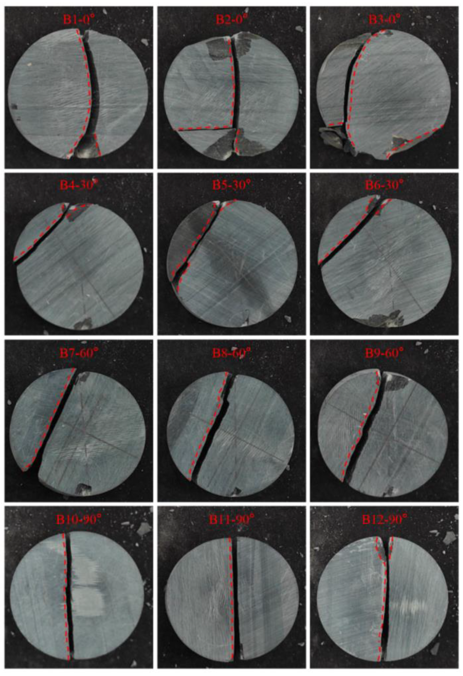
For rock materials, the tensile strength test is of paramount importance because rock masses are frequently subjected to tensile forces in their natural state, and their tensile properties play a crucial role in the stability of engineering structures such as slopes and tunnels. The tensile strength was determined through the Brazilian splitting test, with three sets of parallel tests conducted for each bedding dip angle. The failure characteristics of the AS specimens in the Brazilian splitting tests are shown in Figure 12.
Figure 12 reveals that under indirect tension, AS specimens predominantly exhibit simple crack patterns, typically featuring only one main crack with localized shear fracturing commonly observed at both ends. The splitting failure of AS specimens can be classified into three types: arc-shaped cracks, central cracks, and bedding plane cracks. When the bedding dip angle is 0°, the splitting failure modes of the specimens mainly manifest as arc-shaped crack failure modes traversing the specimens or central crack failure modes. This is because, at this angle, the loading direction is perpendicular to the bedding planes, resulting in the compaction of the bedding planes and an enhancement of the overall strength of the specimens. Consequently, their tensile strength is higher than that of specimens with other dip angles and can be regarded as the tensile strength of the AS matrix. When the bedding dip angles are 30° and 60°, the specimens typically undergo shear failure or partial-path shear failure along the bedding planes, causing the fracture paths to deviate from the vertical centerline of the specimens. At relatively small bedding dip angles, cracks propagate along the bedding planes for a certain distance before deflecting into the rock matrix. As the bedding dip angle increases, cracks tend to propagate directly along the bedding planes. In addition, specimens with bedding dip angles of 60° and 90° usually experience bedding plane crack failure. This is because the load direction applied by the testing apparatus is very close to the orientation of the bedding planes, and the strength of the bedding planes is much lower than that of the rock matrix, making the specimens prone to splitting along the bedding planes. Meanwhile, for specimens with a 90° bedding dip angle, the splitting failure direction starts from the bedding plane at one end, progresses along the bedding plane, and ultimately reaches the other end. Their tensile strength can be approximately considered as the inter-bedding plane tensile strength of the AS.
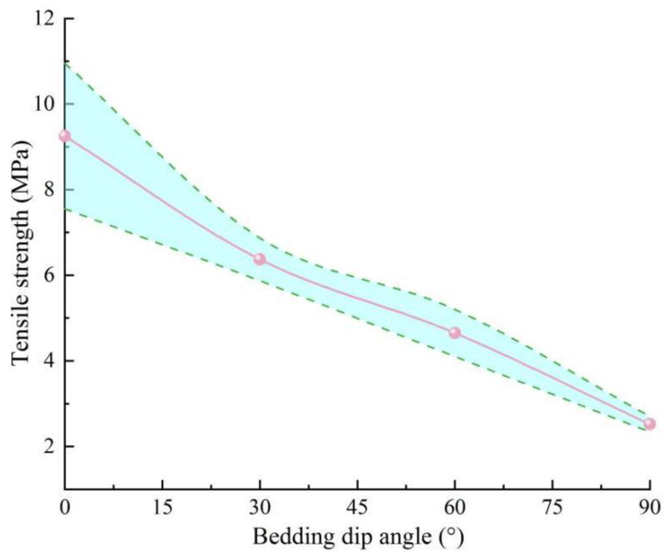
The results of the splitting tests on AS, showing the stress-displacement curves for AS with different bedding dip angles, are presented in Figure 13. The stress-displacement curves exhibit three main stages: First is the crack closure stage, where the stress increases slowly with the rise in vertical displacement. Second is the linear elastic deformation stage, during which the stress shows a linear increase. Finally, there is the failure stage, where the stress drops rapidly after reaching the peak value, and the pre-peak yield stage is not prominent. When the axial load reaches its peak, the stress drops almost vertically, parallel to the stress axis, and some specimens experience ejection, indicating that AS exhibits typical failure characteristics of quasi-brittle materials. As the bedding dip angle increases, the displacement of the specimens gradually decreases, while the tensile strength significantly weakens. This shows that the bedding dip angle has a significant impact on the Brazilian splitting failure characteristics, further demonstrating the strong anisotropy of AS. The mean values and standard deviations of the tensile strength under different bedding dip angles were calculated, and the results are shown in Figure 14. Clearly, AS exhibits significant anisotropic characteristics, with the tensile strength gradually decreasing as the bedding dip angle increases from 0° to 90°. This is because an increase in the bedding dip angle causes the bedding planes to change from being perpendicular to parallel to the loading direction. Since the strength of the bedding planes is much lower than that of the rock matrix, the tensile strength of the rock decreases accordingly.

3.5. Field Grouting Test Results and Analysis

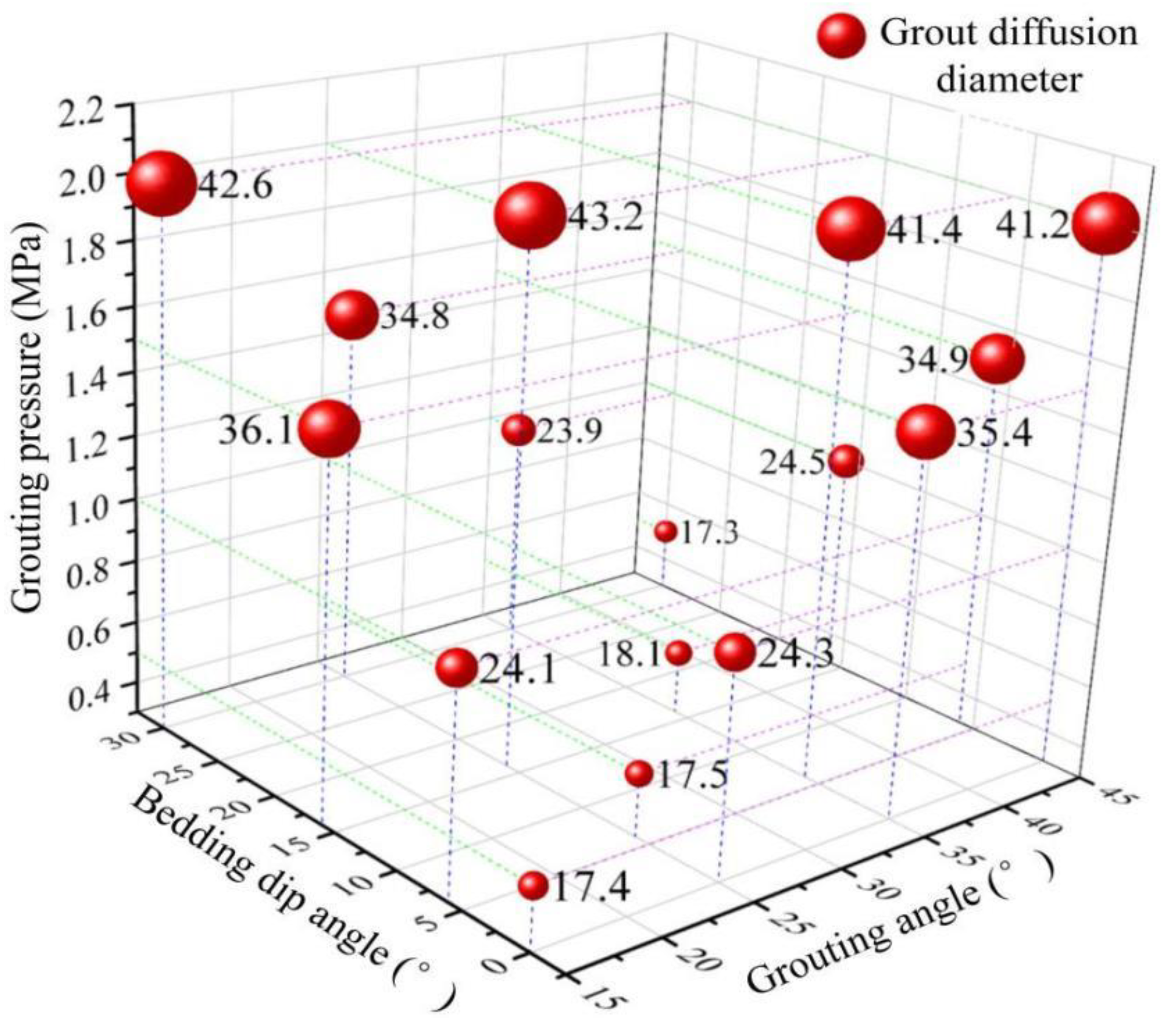
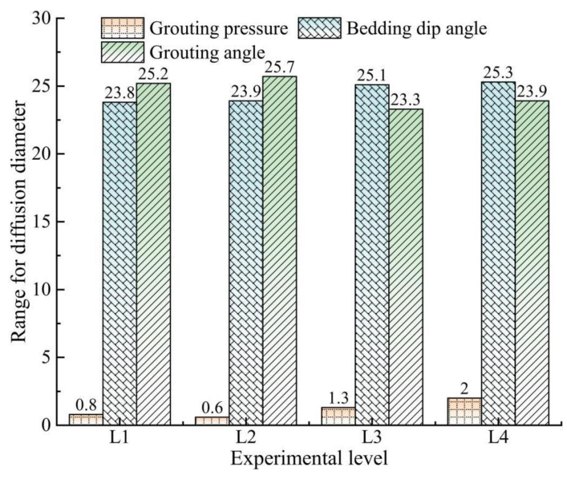
The results of the field grouting tests indicate that, due to the generally consistent degree of bedding development in the AS of the slope, the diffusion of the grout exhibits a regular pattern. The grout mainly diffuses in a nearly circular area centered around the borehole and along the bedding planes (as shown in Figure 3). Through excavation and measurement, the mean values of the grout diffusion diameters under different test conditions in the orthogonal design were obtained (as shown in Figure 15), along with the range analysis under different test levels (as shown in Figure 16). Among the factors influencing the diffusion range of the grout, the bedding dip angle of the rock strata and the borehole dip angle have relatively minor impacts, while the grouting pressure has a more significant effect. The diffusion of the grout is mainly concentrated within a range with a diameter of 17.3–43.2 cm centered around the borehole.
Figure 16 demonstrates that when the grouting pressure is fixed at 0.5 MPa, 1.0 MPa, 1.5 MPa, and 2.0 MPa, respectively, the ranges of the grout diffusion diameters, which are caused by differences in the bedding dip angle and the grouting angle, are 0.8 cm, 0.6 cm, 1.3 cm, and 2.0 cm, respectively. When the bedding dip angle is fixed at 0°, 6°, 16°, and 30°, respectively, the ranges of the grout diffusion diameters, resulting from differences in the grouting pressure and the grouting angle, are 23.8 cm, 23.9 cm, 25.1 cm, and 25.3 cm, respectively. When the grouting angle is fixed at 15°, 25°, 35°, and 45°, respectively, the ranges of the grout diffusion diameters, caused by differences in the bedding dip angle and the grouting pressure, are 25.2 cm, 25.7 cm, 23.3 cm, and 23.9 cm, respectively.
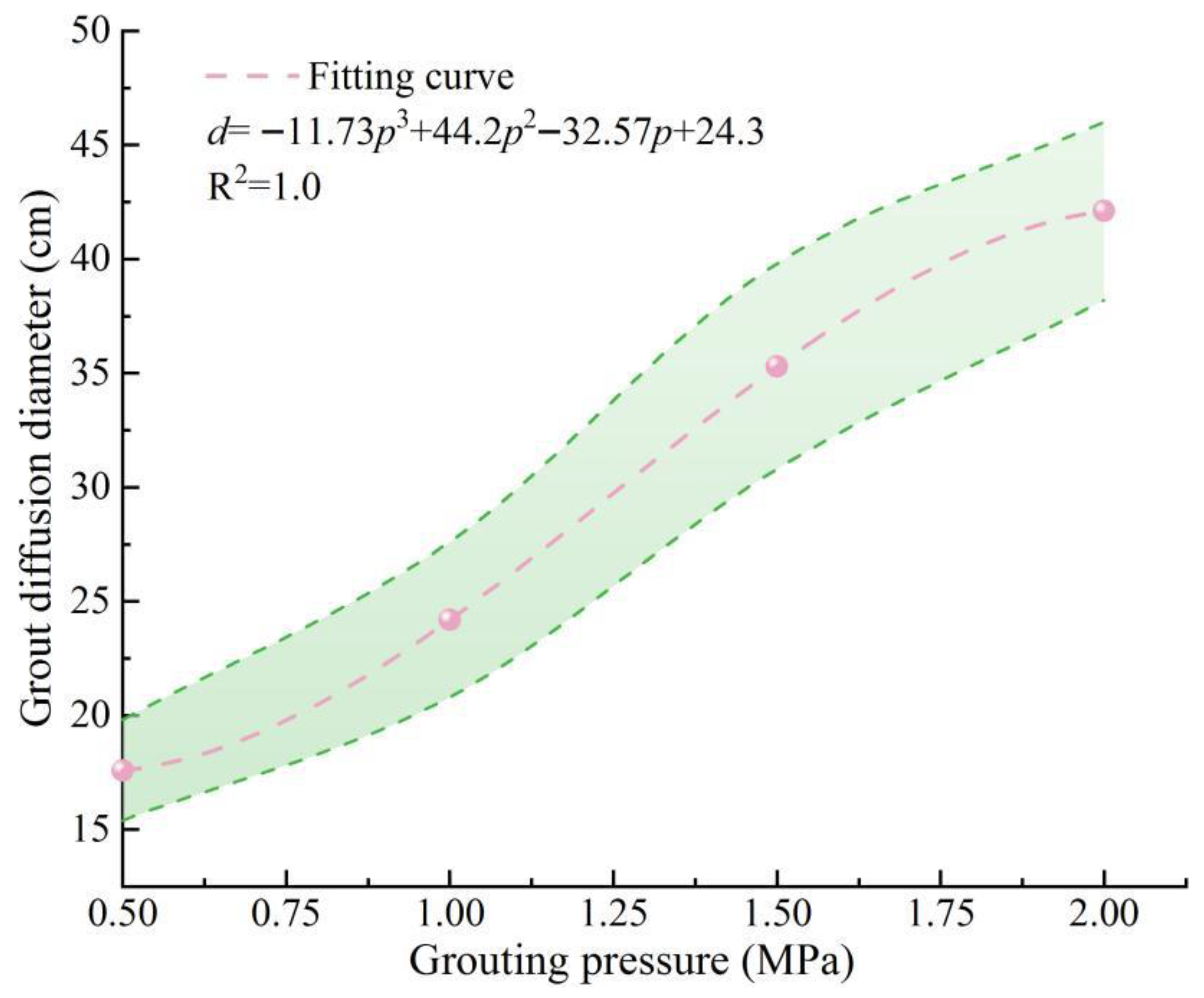
Based on the grout diffusion tests in AS under different grouting pressures, the average values of the grout diffusion diameters (from three sets of parallel tests) and their error bands as a function of the grouting pressure were obtained, as shown in Figure 17. Under certain geological conditions, during the anchorage grouting process of the AS slope at this site, the diffusion effect of the grout in the bedding planes is less influenced by other factors and mainly affected by the grouting pressure. The relationship between the diffusion diameter d and the grouting pressure p can be characterized by a cubic polynomial d = −11.73p3 + 44.2p2 − 32.57p + 24.3, with R2 = 1.0. This allows for accurate prediction of the trend of the diffusion effect in subsequent grouting processes. In the initial stage, a higher grouting pressure leads to a larger diffusion range of the grout. After reaching 1.5 MPa, as the grouting pressure increases, the growth rate of the diffusion range slows down. Unlike free diffusion in rock fractures [47], it is speculated that the diffusion mechanism of the grout in the bedding planes is mainly influenced by two key factors. First, the vibration from the drilling machine may weaken the cementation strength of the bedding planes, providing pathways for the diffusion of the grout. Second, the grouting pressure may cause splitting of the bedding planes, facilitating the diffusion of the grout along them. However, as the diffusion range of the grout increases, the frictional resistance from the rock mass also increases. Especially in areas far from the borehole, the cementation strength of the rock bedding planes does not significantly decrease due to the limited influence of vibration, increasing the resistance to the long-distance diffusion of the grout and thus limiting its diffusion range. Therefore, although the grouting pressure plays a crucial role in promoting the diffusion of the grout in the initial stage, as the diffusion range increases, the frictional resistance of the rock mass and the relatively high cementation strength restrict the further diffusion of the grout, resulting in a limited diffusion range. This process indicates that the diffusion of the grout in the bedding planes is a complex process influenced by multiple factors, and it is necessary to comprehensively consider factors such as vibration effects, grouting pressure, rock mass frictional resistance, and cementation strength.
In summary, the anisotropy in the failure modes of AS is by no means a mere theoretical phenomenon; it directly dictates the determination of rock mass strength values, prediction of failure modes, and the design of reinforcement measures. For geotechnical engineering projects such as slopes, it is essential to clearly ascertain the bedding attitudes before implementing reinforcement construction. During the construction process, it is crucial to dynamically adjust grouting parameters and support schemes based on the actual geological conditions encountered, thereby achieving effective resolution of engineering challenges and an optimal balance between safety and cost-efficiency. The results of this study indicate that in the grouting engineering of argillaceous slate, the grouting pressure is the core factor that predominantly governs the diffusion range, while the influences of bedding dip angle and grouting angle are relatively limited. Based on this finding, we propose an optimization strategy for dynamically regulating grouting pressure through a “stepped pressure increase” mode.

4. Conclusions

With bedding dip angle as the key variable, a series of mechanical tests were conducted on argillaceous slate (AS) in the Changsha area of Hunan Province. Additionally, field grouting tests were carried out on AS slopes, focusing on rock stratum dip angle, grouting pressure, and grouting angle. The following main conclusions were drawn:
(1)
The bedding dip angle significantly influences the failure mode of AS. Rock specimens with bedding dip angles of 0° and 30° primarily experience splitting tensile failure across bedding planes and partial shear failure; those with a 60° dip angle mainly undergo shear-slip failure, while specimens with a 90° dip angle predominantly exhibit splitting tensile failure. An increase in confining pressure causes the failure mode of rock specimens to transition from splitting tension to more complex shear-slip or compound failure, and a greater bedding dip angle leads to a change in the failure mode of rock specimens in splitting tests from arc-shaped and central cracks to cracks along bedding planes.
(2)
In the compression tests on AS, the stress–strain curves, along with the stress-displacement curves in splitting tests, mainly undergo four stages: crack closure, elastic deformation, crack propagation, and post-peak failure. As the bedding dip angle increases, the ultimate strain and peak stress in compression tests exhibit a trend of initially decreasing and then increasing, whereas they continuously decline in splitting tests.
(3)
The bedding dip angle significantly affects mechanical parameters of AS, such as compressive strength and elastic modulus. As the bedding dip angle varies from 0° to 90°, both the compressive strength and shear strength initially decrease and then increase, reaching their maximum at 0° and minimum at 60°. The shear strength of the rock bedding planes is notably lower than that of the matrix. Additionally, the tensile strength of the rock exhibits a declining trend with an increase in the bedding dip angle.
(4)
The high consistency of bedding in AS facilitates the regular diffusion of grout, which predominantly forms a near-circular diffusion zone centered around the borehole on the bedding plane.
(5)
Among the factors influencing the diffusion range of the grout, the bedding dip angle and grouting angle have relatively minor impacts, while the grouting pressure exerts a significant influence. A higher grouting pressure leads to a larger diffusion range; when the pressure exceeds 1.5 MPa, the increase in the diffusion range diminishes, and the diffusion is mainly concentrated within a region with a diameter ranging from 17.3 to 43.2 cm.
Future research will focus on four primary directions: (1) multi-scale influence mechanisms of weathering on argillaceous slate slope stability; (2) long-term coupling characteristics between groundwater and grouting materials; (3) fatigue damage evolution of reinforced structures under cyclic loading; and (4) multi-field coupling assessment of long-term stability. Considering the significant impact of high-temperature environments on structural integrity [48], the mechanical behavior of AS under elevated temperatures is also prioritized. These studies aim to elucidate the long-term performance evolution of grouted AS under combined weathering-groundwater-mechanical loading-high temperature conditions, providing a scientific basis for maintaining long-term stability in rock engineering projects.

Author Contributions

Conceptualization, X.Z., C.D. and Q.Y.; methodology and testing, X.Z., C.D., Y.C., Q.Y., W.Y. and Y.Z.; formal analysis, X.Z., Y.C. and W.Y.; data curation, X.Z., Y.C., C.D. and W.Y. and Q.Y.; writing—original draft preparation, X.Z. and Y.C.; writing—review and editing, C.D., Q.Y. and J.R.; project administration, C.D., Q.Y., J.R. and Y.Z.; funding acquisition, J.R., Y.Z., Q.Y. and C.D. All authors have read and agreed to the published version of the manuscript.

Funding

This study was supported by the National Natural Science Foundation of China (Grant No. 51968010), the Hunan Provincial Natural Science Foundation of China (Grant No. 2025JJ70382), the Excellent Youth Funding of Hunan Provincial Education Department (Grant No. 24B0724 and 22B0790), the Key Youth Project of Yiyang City Philosophy and Social Science Project (Grant No. 2023YS014), the Fundamental Research Funds for the Central Universities of Central South University (Grant No. 2024ZZTS0364), the Project under the Hunan College Students’ Innovation and Entrepreneurship Training Program (Grant No. S20241152702 and S202511527004).

Institutional Review Board Statement

Not applicable.

Informed Consent Statement

Not applicable.

Data Availability Statement

The data used in this study are available from the corresponding author upon reasonable request.

Conflicts of Interest

The authors declare no conflicts of interest.

References

  1. Zuo, Q.J.; Li, Z.M.; Zhang, Z.J.; Tang, L.S.; Li, P.; Han, B.X.; Li, X.Y. Anisotropy of argillaceous slate swelling evolution in water-rich environment. Chin. J. Rock Mech. Eng. 2022, 44, 2210–2224. [Google Scholar] [CrossRef]
  2. Wenk, H.R.; Yu, R.; Cardenes, V.; Lopez-Sanchez, M.A.; Sintubin, M. Fabric and anisotropy of slates: From classical studies to new results. J. Struct. Geol. 2020, 138, 104066. [Google Scholar] [CrossRef]
  3. Squitieri, A.; Amicone, S.; Dinckal, A.; Altaweel, M.; Gur-Arieh, S.; Rohde, J.; Herr, J.J.; Pietsch, S.; Miller, C. A multi-method study of a chalcolithic kiln in the bora plain (Iraqi Kurdistan): The evidence from excavation, micromorphological and pyrotechnological analyses. Open Archaeol. 2022, 8, 853–872. [Google Scholar] [CrossRef]
  4. Han, K.Y.; Zhang, H.; Ding, X.Z.; Ren, L.D.; Shi, C.L.; Pang, J.F. Zircon U-Pb ages and Lu-Hf isotope of the Dongchuan Group in central Yunnan, China, and their geological significance. Acta Geol. Sin. 2020, 94, 1093–1116. [Google Scholar] [CrossRef]
  5. Li, E.; Wei, Y.; Chen, Z.; Zhang, L. Experimental and numerical investigations of fracture behavior for transversely isotropic slate using semi-circular bend method. Appl. Sci. 2023, 13, 2418. [Google Scholar] [CrossRef]
  6. Li, H.; Zhu, K.; Chen, Y.; Chen, B.G.; Zeng, B.W.; Zhang, Z.Q. Formulation and implementation of elastoplastic constitutive model for carbonaceous slate. Bull. Eng. Geol. Environ. 2023, 82, 93. [Google Scholar] [CrossRef]
  7. Ho, N.C.; van der Pluijm, B.A.; Peacor, D.R. Static recrystallization and preferred orientation of phyllosilicates: Michigamme Formation, northern Michigan, USA. J. Struct. Geol. 2001, 23, 887–893. [Google Scholar] [CrossRef]
  8. Price, W.R.; Ronck, C.L. Quarrying for world heritage designation: Slate tourism in North Wales. Geoheritage 2019, 11, 1839–1854. [Google Scholar] [CrossRef]
  9. Cardenes, V.; de León, M.P.; Rodríguez, X.A.; Rubio-Ordonez, X.A.; Rubio-Ordoñez, A. Roofing slate industry in Spain: History, geology, and geoheritage. Geoheritage 2019, 11, 19–34. [Google Scholar] [CrossRef]
  10. Hu, P.; Guo, W.; Wei, L. Applicability study on modified argillaceous slate as subgrade filling for high-speed railway. Appl. Sci. 2022, 12, 2227. [Google Scholar] [CrossRef]
  11. Abenojar, J.; López de Armentia, S.; Martínez, M.A. Slate–cork laminate enhanced with silicone for habitat industry application. Fire 2024, 7, 166. [Google Scholar] [CrossRef]
  12. Zhou, Y.Y.; Feng, X.T.; Xu, D.P.; Fan, Q.X. Experimental investigation of the mechanical behavior of bedded rocks and its implication for high sidewall caverns. Rock Mech. Rock Eng. 2016, 49, 3643–3669. [Google Scholar] [CrossRef]
  13. Kulatilake, P.H.S.W.; Wang, L.; Tang, H.; Liang, Y. Evaluation of rock slope stability for Yujian River dam site by kinematic and block theory analyses. Comput. Geotech. 2011, 38, 846–860. [Google Scholar] [CrossRef]
  14. Zeng, W.; Chen, Z.; Xie, Y.; Chen, Q. Investigation of damage and creep for bedding’s carbonaceous slate with chemical erosion effect. Materials 2023, 16, 5163. [Google Scholar] [CrossRef]
  15. Zuo, Q.; He, X.F.; Wu, Y.Y.; Yi, Q.L.; Zhu, S.; Liu, Y.L.; Jiang, J. Swelling evolution mechanism for argillaceous slate in a hydrochemical environment. Q. J. Eng. Geol. Hydrogeol. 2024, 57, qjegh2023114. [Google Scholar] [CrossRef]
  16. Zuo, Q.J.; Li, P.; Li, X.Y.; Chen, F.B. Swelling damage evolution of argillaceous slate in a water-rich environment. Q. J. Eng. Geol. Hydrogeol. 2023, 56, qjegh2022128. [Google Scholar] [CrossRef]
  17. Tang, S.B.; Li, J.M.; Ding, S.; Zhang, L.T. The influence of water-stress loading sequences on the creep behavior of granite. Bull. Eng. Geol. Environ. 2022, 81, 482. [Google Scholar] [CrossRef]
  18. Zhao, Z.H.; Liu, H.; Gao, X.J.; Feng, Y.H. Meso–macro damage deterioration of weakly cemented red sandstone under the coupling effect of high-humidity and uniaxial loading. Eng. Fail. Anal. 2023, 143, 106911. [Google Scholar] [CrossRef]
  19. Liu, M.; Luo, X.; Bi, R.; Zhou, J.; Du, K. Impacts of bedding angle and cementation type of bedding planes on mechanical behavior of thin-layer structured bedded rocks under uniaxial compression. Geomech. Energy Environ. 2023, 35, 100473. [Google Scholar] [CrossRef]
  20. Yang, X.; Li, J.; Zhang, Y.; Lei, J.; Li, X.; Huang, X.; Xu, C. Experimental study on mechanical properties of anisotropic slate under different water contents. Appl. Sci. 2024, 14, 1473. [Google Scholar] [CrossRef]
  21. Wang, Z.; Feng, G.; Liu, X.; Zhou, Y. An experimental investigation on the foliation strike-angle effect of layered hard rock under engineering triaxial stress path. Materials 2023, 16, 5987. [Google Scholar] [CrossRef]
  22. Deng, X.; Shi, J.; Li, X.; Wang, R.; Zhang, J.; Yang, X. The secondary development and application of the improved nishihara creep model in soft rock tunnels. Buildings 2023, 13, 2082. [Google Scholar] [CrossRef]
  23. Li, L.; Yu, W.; Zhang, X.; Ming, R.; Wang, Q.; Lv, X. Comparative analysis of fracture characteristics and mechanical properties of shale and slate based on triaxial compression test. Chem. Technol. Fuels Oils 2021, 57, 813–817. [Google Scholar] [CrossRef]
  24. Zhang, J.; Liu, X.; Jia, H.; Du, X.; Wang, Z.; Pan, G.; Zhang, M. Fitting of anisotropic strength parameters of laminated shale and its influence on wellbore instability. Geomech. Geophys. Geo-Energy Geo-Resour. 2025, 11, 43. [Google Scholar] [CrossRef]
  25. Steiakakis, E.; Xiroudakis, G.; Lazos, I.; Vavadakis, D.; Bazdanis, G. Stability Analysis of a Multi-Layered Slope in an Open Pit Mine. Geosciences 2023, 13, 359. [Google Scholar] [CrossRef]
  26. Ren, S.; Tao, Z.; He, M.; Pang, S.; Li, M.; Xu, H. Stability analysis of open-pit gold mine slopes and optimization of mining scheme in Inner Mongolia, China. J. Mt. Sci. 2020, 17, 2997–3011. [Google Scholar] [CrossRef]
  27. He, M.C. Latest progress of soft rock mechanics and engineering in China. J. Rock Mech. Geotech. Eng. 2014, 6, 165–179. [Google Scholar] [CrossRef]
  28. Peng, Y.X.; Wu, L.; Peng, H.H.; Hao, Y.; An, Y.L. Theoretical and experimental study on rock resistance coefficient of soft rock tunnel considering creep effect. Arab. J. Sci. Eng. 2020, 45, 4333–4342. [Google Scholar] [CrossRef]
  29. Kien, D.V.; Anh, D.N.; Thai, D.N. Numerical simulation of the stability of rock mass around large underground cavern. Civ. Eng. J. 2022, 8, 81–91. [Google Scholar] [CrossRef]
  30. Song, J.; Lu, Z.; Pan, Y.; Ji, J.; Gao, Y. Investigation of seismic displacements in bedding rock slopes by an extended Newmark sliding block model. Landslides 2023, 21, 461–477. [Google Scholar] [CrossRef]
  31. Chen, G.; Jin, J.; Meng, X.; Qi, T.; Shi, W.; Chong, Y.; Yang, Y.; Bian, S. Influence of tectonic effects on the formation and characteristics of landslide dams on the NE Tibetan Plateau: A case study in the Bailong River Basin, China. Landslides 2024, 21, 2135–2153. [Google Scholar] [CrossRef]
  32. Zhang, J.F.; Zhang, W.Z.; Lu, K.P.; Yang, G.L. Study on failure mechanism and numerical simulation of argillaceous slate in southeastern Guizhou. ACS Omega 2023, 8, 33444–33451. [Google Scholar] [CrossRef]
  33. Kharichkin, A.I.; Babich, D.D.; Galimov, I.M.; Chernyatin, D.V. Influence of load parameters during landslide slope reinforcement with soil nails based on self-drilling hollow steel bars on their bearing capacity and strength properties. Bull. Sci. Res. Cent. Constr. 2024, 40, 70–79. [Google Scholar] [CrossRef]
  34. Deng, C.; Li, L.; Hu, H.; Xu, Z.; Zhou, Y.; Yin, Q.; Chen, J. Effect of magnetized water on the fundamental grouting properties of cement grout under varying magnetization conditions. Sci. Rep. 2025, 15, 700. [Google Scholar] [CrossRef]
  35. Liu, L.P.; Wang, X.G.; Pi, J.; Cao, R.L.; Duan, Q.W.; Zhang, Q. Rock mass behavior during high pressure grouting: An in-situ experimental investigation. Rock Mech. Rock Eng. 2025, 28, 2531–2547. [Google Scholar] [CrossRef]
  36. Li, J.; Zhang, X.; Li, G. Research on the Self-Drilling Anchor Pull-Out Test Model and the Stability of an Anchored Slope. Appl. Sci. 2025, 15, 5132. [Google Scholar] [CrossRef]
  37. Zhang, S.; Shang, D.; Jiang, Y.; Zhang, J.; Chen, H.; Jiang, T. Shear behavior of bolt–grout interfaces under constant normal stiffness: Influence of grout strength and thickness. Deep. Undergr. Sci. Eng. 2025, 1–14. [Google Scholar] [CrossRef]
  38. Li, L.; Deng, C.; Chen, Y.; Xu, Z.; Yan, W.; Zhou, Y. Experimental analysis of the slurry diffusion behavior characteristics of point source grouting and perforated pipe grouting in sandy soil. Buildings 2025, 15, 1133. [Google Scholar] [CrossRef]
  39. Yan, W.Q.; Deng, C.; Cai, Y.H.; Chu, A.K.; Shen, S.F.; Wu, X.Y. The optimization study of karst-filling clay-cement grout based on orthogonal experiment and regression analysis. Materials 2025, 18, 1943. [Google Scholar] [CrossRef] [PubMed]
  40. Li, L.; Deng, C.; Zhou, Y.; Tan, Q.; Yan, W.; Zhou, D.; Zhou, Y. Stability and rheological properties of grouts with waste glass powder as cement replacement: Influences of content and alkali activator. Materials 2025, 18, 353. [Google Scholar] [CrossRef] [PubMed]
  41. Sang, H.; Liu, B.; Liu, Q.; Kang, Y.; Lu, C. Study of Grouting Reinforcement Mechanism in Fractured Rock Mass and Its Engineering Application. Int. J. Geomech. 2024, 24, 04024057. [Google Scholar] [CrossRef]
  42. Zhang, G.S.; Xiao, M.L.; Zhang, Y.D.; Liu, H.Z.; Zhuo, L.; Xie, H.Q.; He, J.D. Experimental and numerical study on the mechanical properties of compressively precracked sandstone repaired by grouting. Constr. Build. Mater. 2022, 350, 128816. [Google Scholar] [CrossRef]
  43. SL/T 264—2020; Test Regulations for Rock in Water Resources and Hydropower Engineering. China Water & Power Press: Beijing, China, 2020.
  44. ASTM D7012-14; Standard Test Methods for Compressive Strength and Elastic Moduli of Intact Rock Core Specimens Under Varying States of Stress and Temperatures. ASTM International: West Conshohocken, PA, USA, 2014.
  45. ASTM D3967-16; Standard Test Method for Splitting Tensile Strength of Intact Rock Core Specimens. ASTM International: West Conshohocken, PA, USA, 2016.
  46. GB 50330-2013; Technical Code for Building Slope Engineering. Standards Press of China: Beijing, China, 2013.
  47. Mu, W.; Li, L.; Liu, H.; Ren, B.; Chen, J.; Wang, X. An experimental study on fracturing response and slurry flow of high-pressure grouting in fractured rock. Rock Mech. Rock Eng. 2024, 57, 4533–4558. [Google Scholar] [CrossRef]
  48. Bolina, F.L.; München, R.M.; Lago, B.D.; Kodur, V. A comparative study between ultra-high-performance concrete structures and normal strength concrete structures exposed to fire. Structures 2024, 68, 107197. [Google Scholar] [CrossRef]
Figure 1. Anisotropic mechanical test samples at different bedding angles ((a) Core preparation for varying bedding angles; (b) Disk specimen preparation for varying bedding angles).
Applsci 15 10415 g001
Figure 2. TAJW-2000 microcomputer controlled electro-hydraulic servo rock testing machine ((a) Uniaxial compression testing apparatus; (b) Triaxial compression testing apparatus; (c) Direct shear testing apparatus; (d) Brazilian splitting testing apparatus).
Applsci 15 10415 g002
Figure 3. Flowchart of grouting test procedure.
Applsci 15 10415 g003
Figure 4. Failure characteristics of AS rock sample in uniaxial compression test.
Applsci 15 10415 g004
Figure 5. Uniaxial compression stress–strain curve of AS under different bedding dip angles.
Applsci 15 10415 g005
Figure 6. The variation law of uniaxial compressive strength and elastic modulus of AS with bedding dip angle.
Applsci 15 10415 g006
Figure 7. Failure characteristics of AS rock sample in triaxial compression test.
Applsci 15 10415 g007
Figure 8. Triaxial compression stress–strain curves of AS under different dip angles.
Applsci 15 10415 g008
Figure 9. The variation law of triaxial compressive strength and elastic modulus of AS with bedding dip angle.
Applsci 15 10415 g009
Figure 10. Failure characteristics of argillaceous slate rock sample in direct shear test.
Applsci 15 10415 g010
Figure 11. Shear stress and normal stress relationship curve.
Applsci 15 10415 g011
Figure 12. Failure characteristics of AS rock sample in Brazilian splitting test.
Applsci 15 10415 g012
Figure 13. Brazilian splitting stress-displacement curve of argillaceous slate under different bedding dip angles.
Applsci 15 10415 g013
Figure 14. Variation in Brazilian tensile splitting strength with bedding dip angle.
Applsci 15 10415 g014
Figure 15. Diffusion diameter of grout under orthogonal experimental conditions.
Applsci 15 10415 g015
Figure 16. Grout diffusion diameter range under different test levels.
Applsci 15 10415 g016
Figure 17. The variation characteristics of diffusion diameter with grouting pressure.
Applsci 15 10415 g017
Table 1. Test factors and level.
Test LevelInfluencing Factor
Bedding Dip Angle (°)Grouting Pressure (MPa)Injection Angle (°)
L100.515
L261.025
L3161.535
L4302.045
Disclaimer/Publisher’s Note: The statements, opinions and data contained in all publications are solely those of the individual author(s) and contributor(s) and not of MDPI and/or the editor(s). MDPI and/or the editor(s) disclaim responsibility for any injury to people or property resulting from any ideas, methods, instructions or products referred to in the content.