Article

Integrating Finite Element Data with Neural Networks for Fatigue Prediction in Titanium Dental Implants: A Proof-of-Concept Study

by
Tomás Gandía-Sastre
1 and
María Prados-Privado
1,2,3,*
1
Modelling, Simulation and Data Analysis Group for Engineering Industrial, UNIE Universidad, Calle Arapiles 14, 28015 Madrid, Spain
2
Escuela Superior de Ingeniería y Tecnología, Universidad Internacional de La Rioja (UNIR), Avenida de la Paz, 137, 26006 Logroño, Spain
3
Faculty of Digital Business, Technology and Law, UTAMED (Universidad Tecnológica Atlántico Mediterráneo), C. de Marie Curie, 1, Campanillas, 29590 Málaga, Spain
*
Author to whom correspondence should be addressed.
Appl. Sci. 2025, 15(19), 10362; https://doi.org/10.3390/app151910362
Submission received: 13 August 2025 / Revised: 11 September 2025 / Accepted: 23 September 2025 / Published: 24 September 2025
(This article belongs to the Special Issue Deep Learning Applied in Dentistry: Challenges and Prospects)

Abstract

Background: Titanium dental implants are widely used, but their long-term mechanical reliability under fatigue loading remains a key concern. Traditional finite element analysis is accurate but computationally intensive. This study explores the integration of finite element analysis data with neural networks to predict fatigue-related responses efficiently. Methods: A dataset of 200 finite element analysis simulations was generated, varying load intensity, load angle, and implant size. Each simulation provided three outputs: maximum von Mises stress, maximum displacement, and fatigue safety factor. A feedforward neural network with two hidden layers (64 neurons each, ReLU activation) was trained using 160 simulations, with 40 reserved for testing. Results: The neural network achieved high accuracy across all outputs, with R2 values of 0.97 for stress, 0.95 for deformation, and 0.92 for the fatigue safety factor. Mean errors across the test set were below 5%, indicating strong predictive performance under diverse conditions. Conclusions: The findings demonstrate that neural networks can reliably replicate finite element analysis outcomes with significantly reduced computational time. This approach offers a promising tool for accelerating implant assessment and supports the growing role of AI in biomechanical design and analysis.

1. Introduction

Modern titanium dental implants have proven remarkably successful for replacing missing teeth, consistently demonstrating longevity rates exceeding 95% for many years [1]. Still, mechanical failures—specifically those caused by structural wear and tear over time—remain a problem, especially when implants experience repetitive chewing forces for lengthy periods [2]. Titanium and its alloys stay the materials of choice for dental implants owing to their superb blend of resilience, resistance to degradation, and compatibility with human biology [3]. That being said, titanium alloys (with an elasticity modulus approximately 110 GPa) and human bone (ranging from 3 to 10 GPa for trabecular bone and to 15 to 30 GPa for cortical bone) differ noticeably in stiffness, which can lead to stress shielding, peri-implant bone resorption, and ultimately implant failure [4].
These biomechanical challenges really highlight how crucial it is to conduct thorough analyses when designing and evaluating implants. Finite element analysis (FEA) has emerged as a vital computational tool in dental biomechanics. It enables researchers to explore stress distributions, anticipate where failures might occur, and simulate various clinical scenarios that would be tough, expensive, or even unethical to test in real life [5].
For instance, Van Staden et al. [6] provided an early review highlighting FEA’s role in advancing implant design. More recently, Ziaie and Khalili [7] employed FEA to predict abutment screw fatigue under cyclic loading, identifying probable failure after approximately 3·105 cycles. Meanwhile, Zieliński et al. [8] took it a step further by combining FEA with physical fatigue testing, uncovering critical areas where cracks might start, all influenced by different loading angles.
Even though finite element analysis is incredibly powerful, it does have its drawbacks when it comes to being used in iterative design or clinical decision-making processes. Creating high-fidelity, patient-specific simulations often involves complex geometry preparation, meshing, and tuning the solver, which can take anywhere from hours to days of computational time. This really limits its usefulness in fast-paced clinical settings. To address this issue, surrogate modeling techniques that leverage machine learning (ML) have started to show great promise. Liang et al. implemented a deep learning model that predicts aortic wall stress distributions based on input geometries, achieving less than 1% error compared to traditional FEA results [9]. Similarly, Lu et al. created a neural network to estimate cartilage stress in the knee during multibody dynamics, significantly cutting down computation time [10]. These examples highlight how artificial neural networks (ANNs) can deliver FEA results with impressive accuracy and speed.
In the field of dental implant biomechanics, researchers are diving into the use of neural networks for various applications, including design optimization, stress prediction, and estimating fatigue life. Griggs introduced a framework based on artificial neural networks (ANN) aimed at optimizing implant geometry to enhance fatigue resistance, taking into account multiaxial loading and material properties [11]. Additionally, physics-informed neural networks are becoming increasingly popular because they can integrate fundamental physical equations into the learning process, which boosts the model’s generalizability and interpretability.
This study showcases a proof-of-concept that combines FEA data with neural networks to predict three crucial biomechanical indicators related to dental implant fatigue behavior: von Mises stress, deformation, and the fatigue safety factor. By focusing on a Grade 4 titanium implant system, the present study explores various geometric and loading scenarios to train and validate an ANN that can accurately estimate FEA results. Therefore, the goal is to speed up the implant development process, lessen the reliance on repetitive simulations, and establish a foundation for real-time, AI-driven biomechanical assessments in clinical environments.

2. Materials and Methods

2.1. Finite Element Analysis Data Generation

A comprehensive numerical analysis was carried out through generating a database of 200 finite element simulations to investigate the stress distribution and fatigue response of dental implants under various loading scenarios and geometric configurations. First, a computer-aided 3D model of a titanium dental implant was designed utilizing SolidWorks® 2024 software before being imported into the ANSYS® Workbench R1 2024 simulation platform for further evaluation.
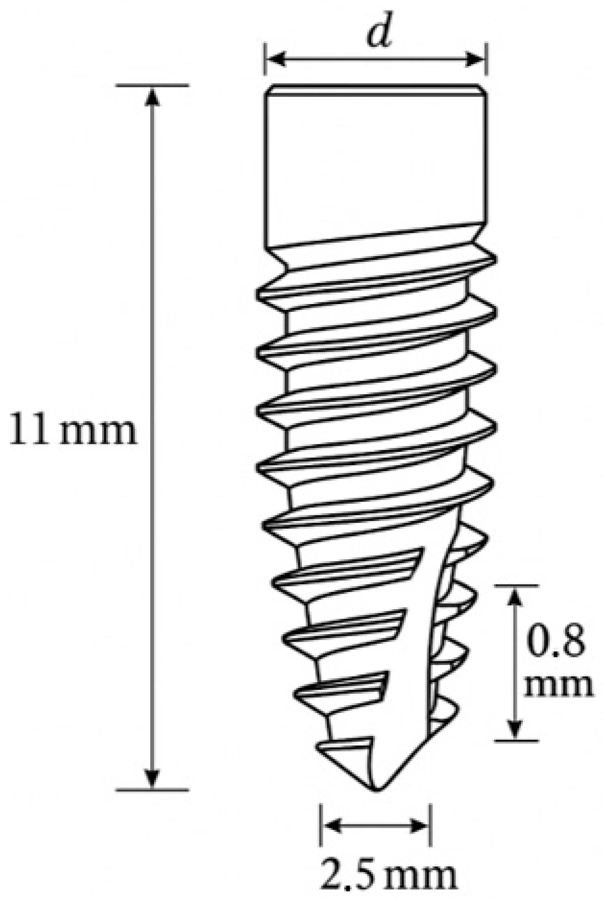
A 3D model of a generic titanium dental implant was designed using SolidWorks®. The implant featured a cylindrical screw-type geometry with a tapered apical end, a standard V-thread profile, and rounded thread edges. The implant’s diameter was parametrically varied between 3.0 and 5.0 mm across simulations, while other dimensions remained fixed (Figure 1). The overall length was 11 mm, thread pitch was 0.8 mm, and core diameter was 2.5 mm. The surrounding jawbone was not explicitly defined; instead, the implant was presumed to have achieved full osseointegration, with rigid fixation at the bone–implant interface, representing a conservative boundary condition for stress evaluation [12]. This virtual implant prototype was then composed within the program using the recognized mechanical attributes of Grade 4 titanium (Young’s modulus = 105 GPa, Poisson’s ratio = 0.34) and fatigue S-N curve parameters [13]. 200 cases were executed for static structural FEA calculations, where each case was defined by a unique combination of:
  • Axial Force (F): 100–800 N (simulating bite forces).
  • Load Angle (A): 0° (pure axial) to 45° (off-axis) in the buccal-lingual dimension, simulating different angles of mastication.
  • Implant Diameter (D): 3.0–5.0 mm (narrow- to wide-platform implants).
The 200 simulation cases were generated using a full-factorial sampling strategy, systematically combining values of the three input variables. Specifically, axial force (F) was varied at 5 levels between 100 N and 800 N, load angle (A) at 5 levels from 0° to 45°, and implant diameter (D) at 8 levels from 3.0 mm to 5.0 mm. This resulted in 5 × 5 × 8 = 200 distinct configurations. This sampling ensured that the model was trained across the entire relevant design space, minimizing interpolation bias.
A distributed load on the occlusal area subjected all experimental conditions to the force exerted on the crown of the implant, following angle A, relative to the long axis of the implant. The lower implant region was fixed in all degrees of freedom to simulate a fully integrated implant in bone. The boundary conditions are represented in Figure 2.
For each simulation, three outcome metrics were calculated to evaluate mechanical performance:
  • Maximum von Mises Stress (σ_VM): scalar values that are used to determine the level of stress and are often used as an indicator of yielding and crack initiation of materials.
  • Maximum Deformation (δ_max): defined as the peak magnitude of nodal displacement within the implant under loading, reported in millimeters (mm).
  • Fatigue Safety Factor (FSF): the ratio between the material’s fatigue endurance limit and the equivalent alternating stress amplitude at critical locations, given the fatigue life target of 5·106 cycles (run-out threshold). The Goodman criterion was employed to calculate FSF, based on the extracted von Mises stress and literature-derived fatigue strength. FSF values greater than 1 implies infinite fatigue life for cyclic loading, whereas FSF values smaller than 1 implies that there is a high possibility of failure occurring before the desired cycle limit.

2.2. Artificial Neural Network Development

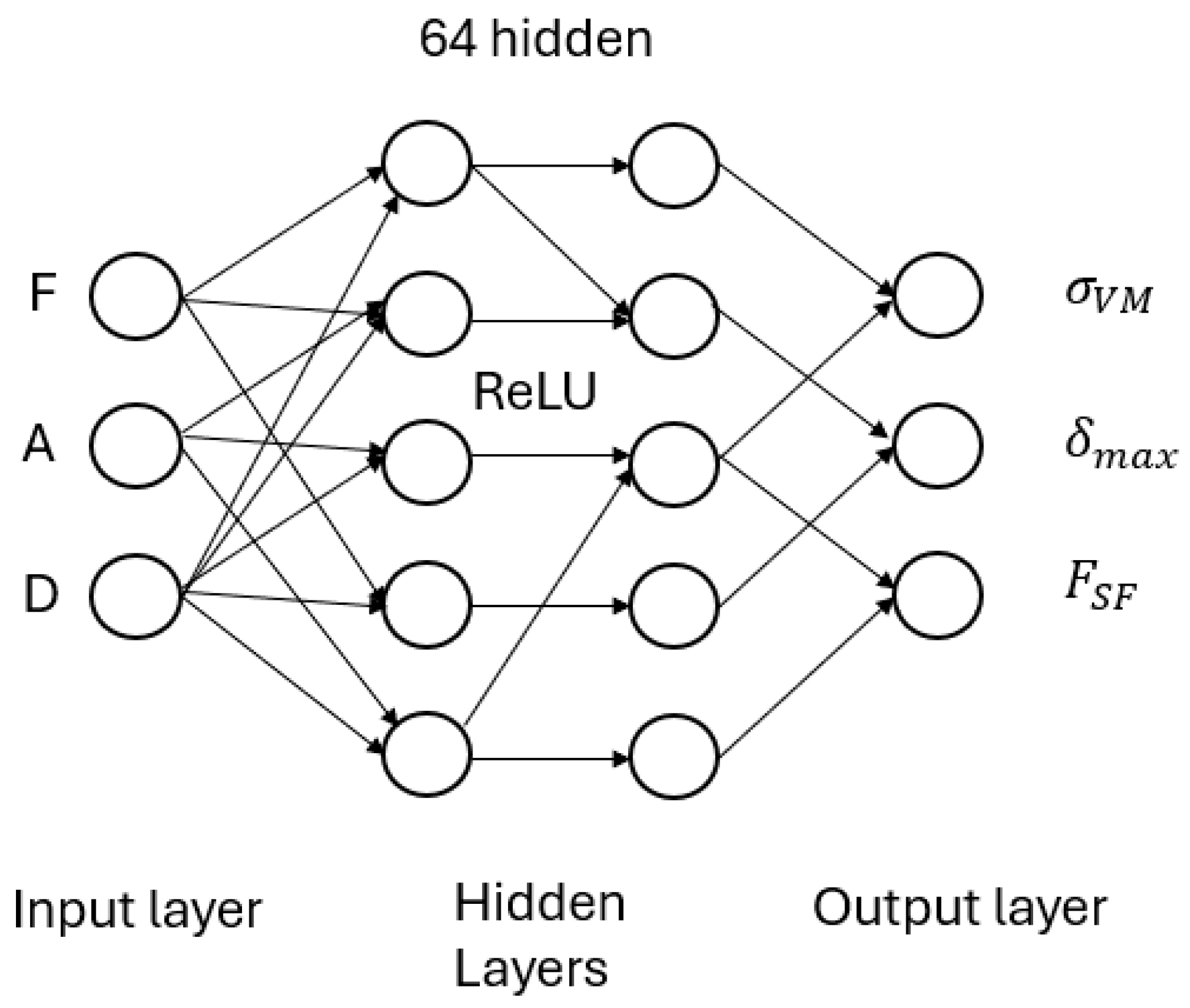
A feed-forward artificial neural network was developed with an uncomplicated and effective architecture for regression (prediction of continuous outputs) with three neurons associated with the normalized values of force (F), angle (A), and diameter (D) in the input layer. We completed feature normalization (zero-mean, unit-variance), so that all inputs were within similar scale values which help with quicker convergence on training.
All FEA models were meshed using ANSYS Workbench’s automatic meshing tools, applying quadratic tetrahedral elements (SOLID187). A global element size of 0.15 mm was used throughout the implant body, while curvature-based refinement with a local element size of 0.05 mm was applied in high-gradient regions such as the implant threads and neck. The mesh typically consisted of ~150,000 to 200,000 elements per model. Mesh convergence studies showed that this resolution resulted in <2% variation in peak von Mises stress, indicating sufficient accuracy for surrogate training.
A mesh convergence study was conducted on a representative implant model under 800 N axial loading at 0° to evaluate sensitivity of the output metrics to mesh refinement. Three meshes were compared, using global element sizes of 0.3 mm, 0.2 mm, and 0.15 mm, with consistent local refinement (0.05 mm) at thread and neck regions. The peak von Mises stress varied by less than 1.9% between the two finest meshes, while displacement showed <1% variation. Based on this, the 0.15 mm mesh was selected for all simulations to ensure numerical stability and convergence of the computed mechanical parameters. The network’s hidden layers were configured as follows: two hidden layers with 64 neurons each, using the Rectified Linear Unit (ReLU) activation function. This architecture was chosen for its balance between complexity and generalization given a relatively small dataset (200 samples). Similar hidden layer sizes have been effectively used in FEA surrogate models with good accuracy. A dropout regularization (rate = 0.1) was applied to each hidden layer during training to mitigate overfitting, considering the limited sample size.
The output layer had three linear neurons producing the predicted σ V M , δ m a x and FSF for a given input F, A and D. No activation function was used in the output layer (identity activation), as this is standard for regression tasks. The network thus represents a function:
f θ F , A , D ( σ V M , δ m a x , F S F )
with trainable parameters θ (weights and biases). Figure 3 represents de ANN architecture.
The model was developed in Python 3.13 with TensorFlow/Keras. The total number of trainable parameters was just under 4500. The authors made the network size small in order to capture the main nonlinear relationships between the inputs and outputs but do so with a chance of overfitting minimized. It also allows rapid execution: a single prediction from the trained network takes milliseconds to execute on a typical CPU; much faster than running a new FEA simulation (which can take minutes per case even for simplified models).

2.3. Training Procedure

The 200 FEA examples were divided into a test set (20%, n = 40) and a training set (80%, n = 160) by random sampling. We randomly partitioned the test set, so it spanned the range of each input to provide an unbiased test of interpolation capabilities. The training employed the Adam optimizer (adaptive moment estimation) with an initial learning rate of 0.001. The loss function was the mean squared error (MSE) averaged across the three outputs:
L θ = 1 3 σ v M σ ^ v M 2 + δ v M δ ^ v M 2 + F S F F ^ S F 2
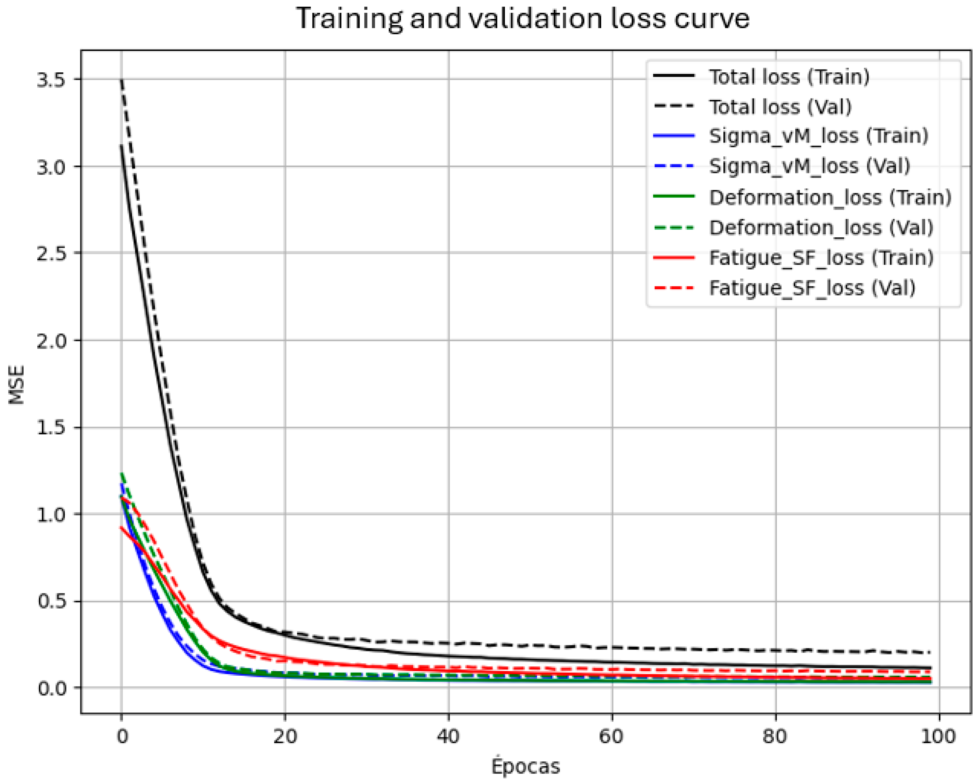
During training, a smoothly decrease loss was observed, with no major spikes, indicating the learning was stable, as Figure 4 shows. The plot highlights consistent reduction across all metrics, with validation loss stabilizing after ~40 epochs. The last training loss (MSE) was on the order of 10−3 (in normalized units), while the validation loss remained slightly higher (≈2 × 10⁻³), reflecting that mild overfitting occurred but was not excessive. The retention of dropout layers combined with L2 weight regularization (λ = 1 × 10⁻⁵) contributed to enhanced generalization.

2.4. Evaluation Metrics

The model’s performance on the independent test set was assessed using several key evaluation metrics. First, the Coefficient of Determination (R2) was calculated for each output variable to measure how much of the variance in the FEA results was captured by the model. An R2 value close to 1 is indicative of strong predictive accuracy and reliability.
In addition to R2, the Mean Absolute Error (MAE) was used to provide an intuitive measure of the model’s average prediction error. MAE was expressed in physical units relevant to each output: megapascals (MPa) for stress, millimeters (mm) for deformation, and unitless for the fatigue safety factor (FSF). To complement this, the mean percentage error was also computed for each output, offering a normalized view of prediction accuracy. This was especially important for FSF predictions, where even small absolute errors could be meaningful due to the values typically being close to 1.
Scatter plots of predicted vs. actual values was examined in order to visually evaluate performance and calculated the Pearson correlation coefficient (which will be in agreement with R2) of each output.

3. Results

3.1. FEA Simulation Outcomes

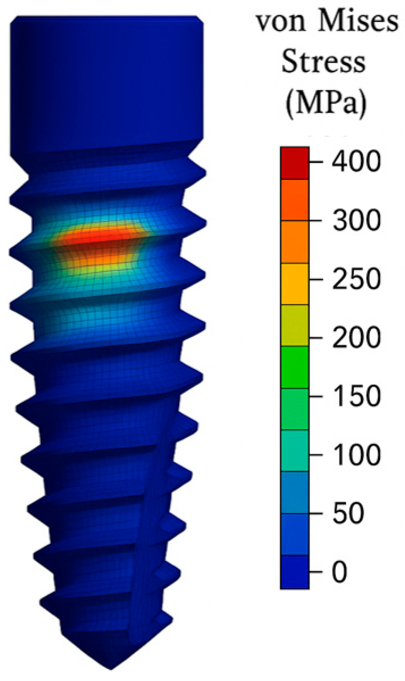
Before presenting the artificial neural network predictions, a careful analysis of the finite element analysis dataset—consisting of 200 test cases—was made in an effort to determine significant mechanical trends. The range of von Mises stress ( σ V M ) throughout the tests varied from a value about 250 MPa, seen with the lowest loads and greatest implant diameters, to those over 820 MPa under an 800 N oblique loading at an applied angle of 45° on the lowest implant diameter. Of particular significance, a high percentage of cases had σ V M values greater than the commercially pure Grade 4 titanium yield strength of approximately 600 MPa and thus the point where plastic deformation began. The most stressed regions were consistently found at either the implant’s neck (specifically near the first threads) or the abutment screw, consistent with clinically identified failure sites. Figure 5 details stress concentrations are located near the implant neck and thread roots, with no isolated spikes. The smooth distribution confirms mesh convergence and numerical stability.
) seen during computer simulation were quite small, generally falling in the range of 5 to 50 μm, in keeping with the high rigidity of titanium. These displacements correlated well with the magnitude of the applied force and inversely with implant size—thickest implants had lower deflection. Maximum values of δ m a x occurred when the specimens were subjected to oblique loading at 45°, where effects of bending were greatest.
The fatigue safety factor (FSF) had a broad spread, ranging from about 0.5—corresponding to high-load, oblique load conditions expected to lead to failure before 106 cycles—through to values in excess of 1.5, characteristic of low-load or larger-diameter implant conditions, demonstrating a high margin of safety. About 30% of the simulated test cases had values of FSF < 1.0, suggesting a finite fatigue life and increased risk of mechanical failure. This broad spread of mechanical response yields a good and representative dataset to train the ANN to separate safe from failure-inducing fatigue conditions.
The FEA results exhibited consistent and expected trends. Increases in axial force and off-axis loading led to higher values of von Mises stress (σ_vM) and maximum deformation (δ_max). Conversely, implants with larger diameters showed reduced stress levels, attributable to their increased cross-sectional area. Notably, several simulations revealed localized stress concentrations at the implant–abutment junction and around the first thread, which are well-documented regions of mechanical vulnerability. Furthermore, an increase in the load angle (A) markedly reduced the fatigue safety factor (FSF), highlighting the detrimental effect of oblique forces on fatigue performance due to elevated bending moments. These mechanical patterns provided a realistic and diverse dataset suitable for training the neural network model.

3.2. Neural Network Prediction Performance

The ANN’s predictive accuracy was tested on a held-out test set of 40 cases not employed in the training process. In prediction of the Von Mises stress, the ANN output closely agreed with reference FEA results, as seen in Figure 6a. In predicting stress, the coefficient of determination (R2) was 0.97, reflecting that the model captured 97% of variance in maximum stresses. Mean absolute error (MAE) was 20.5 MPa, equivalent to an average percent error of 3.2% compared to the mean σVM of about 640 MPa in the test set. Discrepancies were greatest in two test cases where extreme 45° loading occurred, and the model under-predicted stress by some 50 MPa (7% error). These discrepancies result from the sharp rise in bending stresses towards the upper edge of the design space. However, the model accurately identified such cases as high-stress cases, with predicted values over 700 MPa.
At maximum displacement, the ANN had an R2 of 0.95, and a mean absolute error of 1.8 μm, or about 4.5% of the mean deformation (around 40 µm). The model had especially good accuracy in test cases where the magnitude of the force and implant diameters were in the middle range. Minor underestimates occurred in cases with maximum deformations, typically small-diameter implants subjected to high obliques—here the error went up to 5–6 µm. Most importantly, all predicted values of δmax fell well within a ±10% range of their ground-truth values.
Prediction of the fatigue safety factor (FSF) posed a greater challenge due to its inverse relationship with stress and the bounded nature of its values. The ANN achieved an R2 of 0.92 for FSF prediction, with a mean absolute error of 0.06 (unitless) and an average percent error of approximately 4.8%. In most cases, predicted FSF values deviated by less than 0.05 from the FEA-calculated values. A few borderline cases exhibited minor over-predictions—for instance, a true FSF of 0.95 was predicted as 1.02—which could lead to a misclassification of a failing case as safe. However, no false negatives were observed (i.e., the model never predicted failure for a case that was actually safe), which is a favorable outcome in the context of conservative design principles.
Figure 6 below illustrates the correlation between ANN predictions and FEA results for each output. A 45° line is shown for reference. All points lie close to this ideal line, confirming strong agreement.
In addition to numerical accuracy, the ANN offers dramatic computational speed-ups. While our FEA simulations took ~45 s per case, the trained ANN computes all three outputs in under 0.01 s All simulations were performed on a workstation equipped with an AMD Ryzen 9 5900X processor (AMD, Sunnyvale, CA, USA), 32 GB of RAM, and an NVIDIA GeForce RTX 4060 Ti GPU (NVIDIA, Santa Clara, CA, USA) with 16 GB of VRAM. This makes it feasible to perform real-time what-if analyses or optimize implant designs via brute force evaluation of many scenarios–tasks impractical with direct FEA for each iteration.

4. Discussion

The primary goal of the current work is to develop and validate an artificial neural network model able to predict with precision important biomechanical parameters such as von Mises stress, deformation, and fatigue safety factor from data derived from finite element analysis (FEA) with the ultimate goal to optimize dental implant design.
Outcomes corroborate the viability of using neural networks as surrogates to bridge FEA data to predict dental implant fatigue behavior. High R2 (≥0.92) values in all outputs confirm that even a relatively straightforward feed-forward ANN is capable of modeling complex biomechanical correlations in the dataset. This matches the trend in the literature where ANNs have effectively extracted patterns from FEA or experimental data in biomechanical contexts [14,15]. In the current work, the three input parameters (Force, Angle, Diameter) were adequate to account for the majority variance in outcomes, as these were the main variables under variation. Further input parameters (e.g., implant length, thread characteristics, or material properties) can be added in the future to encompass wider implant design spaces.
The data integration strategy applied in this study is particularly noteworthy. Instead of approaching the task purely as a black-box machine learning problem, domain knowledge was incorporated into the development of both the FEA dataset and the ANN architecture. For example, the inclusion of the loading angle as an input variable was based on its established influence on implant stress distribution. By training the model on FEA outputs, the ANN inherently reflects the physical principles embedded in those simulations, at least within the bounds of the training data. Once trained, the ANN functions as a rapid physics-based predictor [16,17].
This approach has promising applications in both implant design and clinical settings. During the design process, engineers can quickly assess the fatigue implications of different implant geometries under varying loads. The ANN enables rapid screening of design options before refinement with detailed FEA. This process is comparable to an optimization loop, where the ANN acts as an estimator of the objective function. Previous studies have proposed the use of neural networks for implant optimization, aiming to enhance fatigue life and reduce undesirable stress shielding. The findings presented here provide concrete validation that such a surrogate modeling approach can be both practical and accurate [18].
Clinically, while the ultimate decision will be not depend solely on stress, the availability of an in-real-time predictive tool whether or not an existing implant (of known diameter) in a particular patient context (estimated biting force and inclination) is in risk of failure due to mechanics would be beneficial. It might, for instance, warn the clinician that an existing 3.3 mm implant under high inclination in a bruxism patient has relatively low fatigue margin, leading to consideration of an implant with higher diameter or the option to opt for an alternative treatment. Incorporation into treatment planning software could further add value to risk assessment on an individual basis. This is part of the overall trend towards personalized medicine and the application of computational tools to surgical planning.
The performance outside of the precise training distribution was also quantified. For instance, a test scenario where the load angle is 60°—just beyond the 45° maximum encountered during training—was considered. The model extrapolated to give large σvM (~900 MPa) and low FSF (~0.4) for an 800 N, 4.0 mm diameter implant for this loading case. This outcome is qualitatively reasonable, since larger angle tends to induce more bending stress.
The surrogate is valid within a constrained domain: Grade 4 titanium, 3.0–5.0 mm implant diameter, 100–800 N static loads at 0–45°, and rigid fixation. Extrapolation (e.g., dynamic loading, other materials, partial osseointegration) requires retraining, validation, and uncertainty quantification. The 60° example is illustrative and not evidence of generalization.
However, such extensions are made cautiously, for even the accuracy for those values outside the training span cannot be guaranteed. The model remains strong within the constraints of the original dataset. The performance suffers slightly for very high-stress and low-FSF values. This limitation can be mitigated through augmentation using additional training examples for that region or through adding physical constraints, e.g., specifying the yield stress that is empirically known to be an upper bound [19,20].
The network learned well the force, angle, and diameter interactions. For instance, keeping force constant, the model captures well more stress and deflection for larger values of angle (due to effects of bending increasing stress). And it captures larger diameter reducing stress nonlinearly, though with diminishing returns for very large diameters.
One such restriction we encountered was handling categorical variation in failure modes–for some simulations, where position of max stress differed (e.g., between abutment and thread). While our own results (=max values) do not offer location, a next-generation version of our model could potentially encompass failure location classification. This information our current ANN does not provide, since it was intended for regression.
Another factor is the absence of bone in our FEA analyses. Practically, bone presence would alter stress distribution differently and could incur results such as bone microstrain or implant-bone interface failure. Our ANN, modeled for in-air simulations of the implant, would need to be reconnected or undergo transfer learning if mechanics for bone were incorporated [5,21].
Our proof of concept utilized a simplified scenario (single implant, no bone, static loading) and subsequent models could potentially include bone and perhaps dynamic loading patterns mimicking actual chewing cycles. The fatigue safety factor which we computed using high-cycle fatigue theory’s Goodman criterion is a simplification and one could favor a more superior one to account for low-cycle fatigue, different failure criteria (e.g., Soderberg, Gerber, etc.) or even directly output cycles to failure. Such models could be trained through data derived from FEA supplemented with fatigue solvers or actual physical fatigue tests corresponding to simulation results [22].
Expanding the surrogate’s scope requires integrating orthotropic bone domains, contact-based osseointegration, and fatigue under multi-axial loading. These additions will be phased through a roadmap combining high-fidelity FEA, ANN retraining with calibrated UQ, and eventual clinical integration—bridging static implant modeling with real-world complexity.
Also, even though our focus was regression, classification models could predict categorical variables (fail or no fail for selected cycles) that might be more clinically interpretable for chosen cases. A third alternative, physics-informed neural networks (PINNs) offer a way for inclusion of known physical constraints (like stress equilibrium or S-N curves) during learning. For example, a PINN could be designed to impose Basquin’s fatigue equation automatically during data fitting and enhance reliability in extrapolations [23,24].
Another potential future direction is expanding the input parameter space. In addition to geometry and loading, one could include surface treatment (roughness), material choices (titanium versus new alloys or PEEK), and even bone quality (D1 dense versus D4 soft bone) and others. Each would necessitate more data, but active learning methods might be able to reduce needed FEA simulations through recognition of most informative cases.
The idea of replacing traditional finite element analysis with machine learning is no longer a speculative detour—it is becoming a credible alternative in computational biomechanics. A striking illustration comes from the work of Liang et al., who demonstrated that a deep neural network could predict full-field aortic wall stresses with less than 1% error [9]. Their approach, fueled by imaging-based geometry and leveraging a sophisticated convolutional neural network (CNN), tackled a problem of considerable anatomical and computational complexity.
In contrast, our study deals with a more structured input-output relationship, where a simpler artificial neural network was not only sufficient but remarkably effective. This simplicity, however, does not diminish the significance of the task. It underscores the importance of architectural alignment between model complexity and problem structure.
Lu et al. previously explored the synergy between multibody dynamics and ANN for estimating cartilage stress in the knee joint. While their results indicated improved computational speed and acceptable accuracy, a closer reading suggests they focused on predicting stress at discrete locations rather than global maxima—an important distinction in biomechanical applications [10].
Liang et al. developed a framework for full-field stress prediction using convolutional neural networks (CNNs) trained on geometry encodings derived from medical imaging. Their method optimizes pixel- or voxel-wise loss functions to replicate the spatial distribution of stress, enabling detailed field-level outputs. However, this approach typically demands larger model capacity and substantially more data to capture fine-grained patterns across spatial domains [10].
In contrast, our problem formulation is inherently low-dimensional, with inputs comprising only force magnitude (F), insertion angle (A), and implant diameter (D), and outputs limited to scalar quantities—namely, von Mises stress (σᵥᴹ), maximum displacement (δₘₐₓ), and the failure safety factor (FSF). Given this structure, a compact multilayer perceptron (MLP) is more appropriate, prioritizing computational efficiency and data economy over spatial resolution.
A middle-ground approach is presented by Lu et al. [10], whose ANN functions as an emulator within a multibody dynamics framework, predicting location-specific cartilage stresses based on system-level kinematic inputs. This represents an intermediate level of model complexity—balancing local specificity with broader system interactions.
Our model, by contrast, is designed to directly map (F, A, D) to global stress extrema and FSF, enabling rapid, interactive “what-if” analyses during implant design or planning. Collectively, these comparisons illustrate a general design principle: the choice of model architecture should align with the nature of the prediction target (full-field vs. localized vs. global scalar), the dimensionality of the input data, and latency or data availability constraints.
To our knowledge, this is among the first studies to apply an ANN to FEA-derived data from dental implants, specifically targeting fatigue-related outputs. In doing so, it offers not only a proof of concept but a practical pathway toward AI-driven design methodologies. Our work aligns closely with the vision articulated by Griggs [11], who proposed AI as a transformative tool in implant design. Here, we provide a tangible step in that direction: a functioning model that could be readily adapted for generative or optimization-based tasks in future implant development.
Although our current dataset of 200 finite element analysis (FEA) simulations suffices to demonstrate the feasibility of the proposed surrogate model, the development of a more robust and generalizable surrogate will benefit from the incorporation of a larger and more diverse dataset. Expanding the dataset will help reduce variance, improve generalization, and stabilize predictions—particularly near the boundaries of the design domain.
As part of our future work, we aim to extend the design space by adopting space-filling sampling techniques, such as Latin hypercube designs, alongside adaptive or active sampling strategies guided by model uncertainty or prediction error. This will enable targeted enrichment of the training dataset in regions where the surrogate model exhibits reduced predictive reliability or higher output sensitivity (e.g., under conditions of extreme obliquity or reduced geometrical dimensions). While we currently report point estimates derived from a held-out test set to provide clarity in performance metrics, small and structured datasets—such as ours—are better served by resampling-based validation strategies that more accurately reflect generalization performance. In future work, we intend to adopt K-fold cross-validation (e.g., K = 5) and repeated hold-out validation to quantify variability induced by data partitioning. Performance will be summarized using robust statistics, such as the median and interquartile ranges (IQRs) of R2, mean absolute error (MAE), and root mean squared error (RMSE) across folds.
Ultimately, if artificial neural networks (ANNs) are to inform safety-critical decisions, their reliability must be validated with the same rigor traditionally reserved for established engineering methods. We advocate for a hybrid approach: leveraging ANN predictions for rapid insights and early-stage design filtering, then applying targeted FEA simulations to the most critical or ambiguous cases for final verification. This strategy preserves the high standards of decision trustworthiness while capitalizing on the speed and efficiency that AI offers.
Looking ahead, the potential for continuous improvement is clear. As more data become available—including real-world clinical outcomes—the ANN can be iteratively retrained, gradually refining its accuracy and broadening its ability to capture patient- and design-specific variability.
Even at this preliminary stage, the ANN has performed exceptionally well within its defined scope: predicting key FEA outcomes for dental implants based on load and geometric parameters. It is, we believe, a promising first step toward integrating AI not as a replacement, but as a powerful partner in biomechanical design and evaluation.
The surrogate can be deployed as a REST API or SDK, embedded in clinical CAD platforms, accepting DICOM/CBCT and mesh inputs and returning FSF/σᵥᴹ/δₘₐₓ predictions with uncertainty and safety checks. Regulatory compliance requires alignment with IEC 62304, ISO 14971, IEC 62366, and GDPR [25,26,27,28]. Deployment includes model versioning, real-world validation, and drift monitoring to support reliable clinician use.

5. Conclusions

This study proposes a novel yet grounded integration of finite element analysis data with a feed-forward neural network, aimed at predicting fatigue-related mechanical responses in titanium dental implants. The approach reflects a growing paradigm in computational biomechanics—where artificial intelligence does not replace physics, but rather accelerates its practical application.
The neural network was trained on a triplet of input variables—applied force, angulation, and implant diameter—to estimate three biomechanical outputs derived from FEA: von Mises stress, total deformation, and the fatigue safety factor. Across all predicted variables, the model achieved a coefficient of determination (R2) exceeding 0.90, with average errors hovering around 5%. In other words, the network learned not just to interpolate data, but to approximate a highly nonlinear mechanical process with remarkable fidelity.
The advantage is not merely predictive accuracy, but speed. Traditional FEA, though robust, is computationally expensive—often prohibitively so for iterative design or real-time scenarios. In stark contrast, the trained network delivers near-instantaneous results, enabling large-scale parametric sweeps and unlocking new possibilities in clinical decision-making and design optimization workflows.
A crucial pillar of this framework lies in the thoughtful incorporation of domain knowledge: from the generation of simulation datasets to the careful selection of inputs. The fidelity of the results underscores the importance of interdisciplinary synergy—where engineering expertise informs machine learning, and vice versa. This foundation also allows for scalability: the methodology is readily extendable to more complex scenarios, including bone–implant interactions, time-dependent loading, or even physics-informed neural networks for enhanced generalizability.
This study presents several limitations that must be acknowledged before any clinical or industrial application. First, all simulations were performed under static loading conditions, without incorporating the dynamic, cyclic forces typical of mastication. This significantly limits the model’s applicability to real-world fatigue scenarios. Although the fatigue safety factor was estimated using the Goodman criterion, more comprehensive fatigue life predictions (e.g., number of cycles to failure) were not included. From a geometric perspective, only the implant diameter was varied, while other critical features such as implant length, thread profile, and neck geometry remained fixed. This reduces the surrogate model’s ability to generalize across a wider range of implant designs. Furthermore, the ANN was trained within a constrained input domain—loads from 100 to 800 N, angles from 0° to 45°, and diameters from 3.0 to 5.0 mm—which limits its reliability outside this region unless retraining and validation are performed. Another important limitation is that the network only predicts global output values (maximum stress, deformation, and FSF) without providing spatial information or localizing stress concentrations. As such, it does not distinguish whether critical stress points occur at the implant neck, abutment screw, or thread roots—locations clinically relevant for failure prediction and design optimization. Finally, the model assumes full osseointegration and excludes any representation of surrounding bone or patient-specific anatomy. Consequently, factors such as bone density, bruxism, and anatomical variability are not yet captured. These limitations should be carefully considered when interpreting the results, and future work must address them by incorporating dynamic fatigue models, expanding the geometric and clinical parameter space, and validating predictions with real patient data to ensure translational relevance.
In conclusion, this convergence between finite element modeling and artificial intelligence marks a significant step forward in implant biomechanics. By uniting the precision of traditional simulation with the speed and adaptability of AI, researchers are now better equipped to explore broader design spaces, anticipate mechanical failures, and ultimately improve clinical outcomes in dental implantology.
Author Contributions

Conceptualization, M.P.-P.; methodology, M.P.-P. and T.G.-S.; validation, M.P.-P.; formal analysis, M.P.-P. and T.G.-S.; data curation, T.G.-S.; writing—original draft preparation, M.P.-P.; writing—review and editing, M.P.-P. and T.G.-S.; visualization, M.P.-P. and T.G.-S.; supervision, M.P.-P. All authors have read and agreed to the published version of the manuscript.

Funding

This research received no external funding.

Institutional Review Board Statement

Not applicable.

Informed Consent Statement

Not applicable.

Data Availability Statement

The original contributions presented in this study are included in the article. Further inquiries can be directed to the corresponding author.

Conflicts of Interest

The authors declare no conflicts of interest.

Abbreviations

The following abbreviations are used in this manuscript:
ANNArtificial Neural Network
FEAFinite Element Analysis
PINNPhysics-Informed Neural Networks
ReLURectified Linear Unit
MAEMean Absolute Error

References

  1. Pjetursson, B.E.; Thoma, D.; Jung, R.; Zwahlen, M.; Zembic, A. A systematic review of the survival and complication rates of implant-supported fixed dental prostheses (FDPs) after a mean observation period of at least 5 years. Clin. Oral Implant. Res. 2012, 23, 22–38. [Google Scholar] [CrossRef]
  2. Albrektsson, T.; Zarb, G.; Worthington, P.; Eriksson, A.R. The long-term efficacy of currently used dental implants: A review and proposed criteria of success. Int. J. Oral Maxillofac. Implant. 1986, 1, 11–25. [Google Scholar]
  3. Elias, C.N.; Lima, J.H.C.; Valiev, R.; Meyers, M.A. Biomedical Applications of Titanium and its Alloys. J. Miner. Met. Mater. Soc. March. 2008, 60, 46–49. [Google Scholar] [CrossRef]
  4. Gasik, M.; Lambert, F.; Bacevic, M. Biomechanical Properties of Bone and Mucosa for Design and Application of Dental Implants. Materials 2021, 14, 2845. [Google Scholar] [CrossRef]
  5. Geng, J.P.; Tan, K.B.; Liu, G.R. Application of finite element analysis in implant dentistry: A review of the literature. J. Prosthet. Dent. 2001, 85, 585–598. [Google Scholar] [CrossRef] [PubMed]
  6. Van Staden, R.C.; Guan, H.; Loo, Y.C. Application of the finite element method in dental implant research. Comput. Methods Biomech. Biomed. Eng. 2006, 9, 257–270. [Google Scholar] [CrossRef] [PubMed]
  7. Ziaie, B.; Khalili, S.M.R. Evaluation of Fatigue Life for Dental Implants Using FEM Analysis. Prosthesis 2021, 3, 300–313. [Google Scholar] [CrossRef]
  8. Zieliński, R.; Lipa, S.; Piechaczek, M.; Sowiński, J.; Kołkowska, A.; Simka, W. Finite Element Analysis and Fatigue Test of INTEGRA Dental Implant System. Materials 2024, 17, 1213. [Google Scholar] [CrossRef]
  9. Liang, L.; Liu, M.; Martin, C.; Sun, W. A deep learning approach to estimate stress distribution: A fast and accurate surrogate of finite-element analysis. J. R. Soc. Interface 2018, 15, 20170844. [Google Scholar] [CrossRef]
  10. Lu, Y.; Pulasani, P.R.; Derakhshani, R.; Guess, T.M. Application of neural networks for the prediction of cartilage stress in a musculoskeletal system. Biomed. Signal Process. Control. 2013, 8, 475–482. [Google Scholar] [CrossRef]
  11. Griggs, J.A. Artificial Neural Networks for the Design Optimization of Implants. In Artificial Intelligence in Dentistry; Springer International Publishing: Berlin/Heidelberg, Germany, 2023; pp. 83–96. [Google Scholar] [CrossRef]
  12. Chou, H.-Y.; Müftü, S.; Bozkaya, D. Combined effects of implant insertion depth and alveolar bone quality on periimplant bone strain induced by a wide-diameter, short implant and a narrow-diameter, long implant. J. Prosthet. Dent. 2010, 104, 293–300. [Google Scholar] [CrossRef]
  13. Boyer, H.E. Atlas of Fatigue Curves; ASM International: Almere, The Netherlands, 2006. [Google Scholar]
  14. Choudhury, S.; Rana, M.; Chakraborty, A.; Majumder, S.; Roy, S.; RoyChowdhury, A.; Datta, S. Design of patient specific basal dental implant using Finite Element method and Artificial Neural Network technique. Proc. Inst. Mech. Eng. Part H J. Eng. Med. 2022, 236, 1375–1387. [Google Scholar] [CrossRef]
  15. Roy, S.; Dey, S.; Khutia, N.; Roy Chowdhury, A.; Datta, S. Design of patient specific dental implant using FE analysis and computational intelligence techniques. Appl. Soft Comput. 2018, 65, 272–279. [Google Scholar] [CrossRef]
  16. Watanabe, F.; Hata, Y.; Komatsu, S.; Ramos, T.C.; Fukuda, H. Finite element analysis of the influence of implant inclination, loading position, and load direction on stress distribution. Odontology 2003, 91, 31–36. [Google Scholar] [CrossRef]
  17. Zhang, P.; Tang, K.; Wang, A.; Wu, H.; Zhong, Z. Neural network integrated with symbolic regression for multiaxial fatigue life prediction. Int. J. Fatigue 2024, 188, 108535. [Google Scholar] [CrossRef]
  18. Marković, E.; Marohnić, T.; Basan, R. A Surrogate Artificial Neural Network Model for Estimating the Fatigue Life of Steel Components Based on Finite Element Simulations. Materials 2025, 18, 2756. [Google Scholar] [CrossRef]
  19. Lacki, P.; Derlatka, A.; Kasza, P.; Gao, S. Numerical study of steel–concrete composite beam with composite dowels connectors. Comput. Struct. 2021, 255, 106618. [Google Scholar] [CrossRef]
  20. Sun, Y.; Veysset, D.; Nelson, K.A.; Schuh, C.A. The Transition from Rebound to Bonding in High-Velocity Metallic Microparticle Impacts: Jetting-Associated Power-Law Divergence. J. Appl. Mech. 2020, 87, 091002. [Google Scholar] [CrossRef]
  21. Papavasiliou, G.; Kamposiora, P.; Bayne, S.C.; Felton, D.A. Three-dimensional finite element analysis of stress-distribution around single tooth implants as a function of bony support, prosthesis type, and loading during function. J. Prosthet. Dent. 1996, 76, 633–640. [Google Scholar] [CrossRef]
  22. Martinez-Mondragon, M.; Urriolagoitia-Sosa, G.; Romero-Ángeles, B.; García-Laguna, M.A.; Laguna-Canales, A.S.; Pérez-Partida, J.C.; Mireles-Hernández, J.; Carrasco-Hernández, F.; Urriolagoitia-Calderón, G.M. Biomechanical Fatigue Behavior of a Dental Implant Due to Chewing Forces: A Finite Element Analysis. Materials 2024, 17, 1669. [Google Scholar] [CrossRef] [PubMed]
  23. Raissi, M.; Perdikaris, P.; Karniadakis, G.E. Physics-informed neural networks: A deep learning framework for solving forward and inverse problems involving nonlinear partial differential equations. J. Comput. Phys. 2019, 378, 686–707. [Google Scholar] [CrossRef]
  24. Zhang, X.-C.; Gong, J.-G.; Xuan, F.-Z. A physics-informed neural network for creep-fatigue life prediction of components at elevated temperatures. Eng. Fract. Mech. 2021, 258, 108130. [Google Scholar] [CrossRef]
  25. UNE-EN 62304:2007/A1:2016; Medical Device Software—Software life-Cycle Processes. Spanish Association for Standardization: Madrid, Spain, 2016.
  26. UNE-EN ISO 14971:2020; Medical Devices—Application of Risk Management to Medical Devices. ISO: Geneva, Switzerland, 2020.
  27. UNE-EN 62366-1:2015; Medical Devices—Part 1: Application of Usability Engineering to Medical Devices (Endorsed by AENOR in June of 2015). Spanish Association for Standardization: Madrid, Spain, 2015.
  28. GDPR 2016/679; Reglamento General de Protección de Datos (RGPD) o Reglamento (UE). European Comission: Brussels, Belgium, 2016.
Figure 1. Geometric schematic of the dental implant used in simulations. The model has a cylindrical screw-type profile with a tapered apex, total length of 11 mm, coronal diameter (d between 3.0 and 5.0 mm, core diameter 2.5 mm, and thread pitch of 0.8 mm.
Applsci 15 10362 g001
Figure 2. Schematic representation of boundary conditions used in FEA.
Applsci 15 10362 g002
Figure 3. Artificial neural network architecture for multivariable regression based on normalized input parameters (F, A, D).
Applsci 15 10362 g003
Figure 4. Evolution of the mean squared error (MSE) during training and validation for total and component losses.
Applsci 15 10362 g004
Figure 5. Representative von Mises stress distribution in the dental implant for a high-load, oblique case (150 N, 45°, 3.0 mm diameter). Maximum displacement ( δ m a x
Applsci 15 10362 g005
Figure 6. Predicted vs. FEA true values for (a) von Mises stress; (b) fatigue safety factor on the test dataset (40 cases). The neural network predictions closely track the FEA results (R2 > 0.90 for all outputs).
Applsci 15 10362 g006
Disclaimer/Publisher’s Note: The statements, opinions and data contained in all publications are solely those of the individual author(s) and contributor(s) and not of MDPI and/or the editor(s). MDPI and/or the editor(s) disclaim responsibility for any injury to people or property resulting from any ideas, methods, instructions or products referred to in the content.