Article

Evaluation of Dental Trauma Splints in Early Permanent Dentition Through Finite Element Analysis

by
Sevde Berfu Zaim
1,* and
Firdevs Kahvecioğlu
2
1
Nuh Çimento Industry Foundation Oral and Dental Health Center, Kocaeli 41000, Türkiye
2
Department of Pedodontics, Faculty of Dentistry, Selçuk University, Konya 42075, Türkiye
*
Author to whom correspondence should be addressed.
Appl. Sci. 2025, 15(19), 10307; https://doi.org/10.3390/app151910307
Submission received: 6 July 2025 / Revised: 15 September 2025 / Accepted: 17 September 2025 / Published: 23 September 2025
(This article belongs to the Special Issue Recent Advances in Pediatric Orthodontics and Pediatric Dentistry)

Abstract

Background: This study aims to evaluate the stress accumulation and distribution created by three different splint types and lengths in the early permanent dentition teeth, using finite element analysis. Methods: A total of 10 simulations were performed using three different splint materials, three different splint lengths, and a control group. Using finite element analysis, a vertical and an oblique force with 150 N was applied to the teeth. von Mises stress and its amounts occurring in enamel, dentin, and pulp as a result of the applied forces were evaluated. Results: In the control and operating models, it was determined that the highest von Mises stress values under vertical and oblique forces occurred at the points where the forces were applied. It was determined that the highest von Mises stress value in splint materials under vertical and oblique forces was in the composite orthodontic wire splint group. It was observed that the most negative results in terms of rigidity were observed in the composite orthodontic wire splint, and the most positive results were observed in the nylon fishing line splint. Conclusions: Within the limitations of this study, the results demonstrate that different splint materials and splint lengths showed varying stress distribution patterns. These findings provide useful insight into the biomechanical behavior of dental trauma splints and may help in selecting appropriate splinting approaches. Further studies on this subject are needed to better understand the effects of these materials on enamel, dentin, and pulp.

1. Introduction

Traumatic dental injuries are a significant oral health issue in children, ranking second only to dental caries, and they can have long-lasting psychological effects. The ongoing development of motor skills during growth contributes to the higher rate of dental trauma in children compared to adults. When trauma changes the position of a tooth, treatment begins with quick repositioning into the socket, followed by stabilization to restore normal function and promote periodontal healing. In cases where teeth are displaced from their usual position in the dental arch, accurate repositioning is essential before proceeding with further treatment. The splint must be applied carefully to prevent additional pulpal or periodontal damage, as this is crucial for the tooth’s long-term survival. Splinting remains one of the most vital steps in managing traumatized teeth, aiding both the healing process and the recovery of surrounding tissues [1].
In the healing process, both the duration of splinting and the flexibility of the splint are crucial. Prolonged splinting with a rigid material, especially for more than 14 days, has been linked to increased stress buildup, which may cause complications such as ankylosis, greater root resorption, and pulp canal obliteration [2]. A wire thickness of 0.4 mm has been identified as the limit for maintaining flexibility in splints; when this threshold is exceeded, the splint becomes rigid and acts as a rigid fixation [3].
Two key factors are vital for effective treatment: applying light force to the healing tissues and controlling the movement of teeth within the traumatized socket, usually around 50 μm [4]. Splinting changes the direction of forces on the teeth, turning potentially harmful lateral forces into vertical ones, which are less damaging to the supporting structures [5]. Finite element analysis has shown that static and dynamic forces on models can range from 100 N to 2000 N. In one study, Poiate et al. [6] identified 100 N as the applied force level, with normal chewing forces averaging 500 N. Forces around 800 N were considered parafunctional or traumatic.
A variety of splints have been developed and utilized over time. Common options include composite orthodontic wire splints, nylon fishing line splints, titanium trauma splints, and fiber splints [7]. Composite orthodontic wire splints made with metallic wires of 0.45 mm, or more are generally classified as rigid fixation devices, while nylon fishing line and titanium trauma splints are seen as flexible alternatives [8]. Despite their widespread use, there is limited evidence regarding the performance of these materials during the early permanent dentition stage.
The performance of splint designs is most often evaluated through in vitro studies. For this purpose, various techniques have been employed, including the photoelastic stress analysis method, the strain gauge analysis method, the brittle lacquer technique, the holographic interferometer (laser light) method, and finite element analysis. While each of these approaches has specific advantages and limitations, finite element stress analysis provides the ability to quantify localization, stress type, and distribution with greater detail, as mathematical values can be obtained from the models [9]. Finite element analysis has been widely used to study the biomechanical behavior of complex structures. It is therefore considered a suitable and reliable method for assessing splint performance [10].
This study aims to assess stress accumulation and distribution related to three different splint types and material lengths on teeth and surrounding tissues during the early permanent dentition period using finite element analysis. The null hypothesis was that finite element analysis would show no differences between splint types or material lengths in stress accumulation and distribution within the enamel, dentin, and pulp.

2. Materials and Methods

In this study, dental tomography images from an 11-year-old female patient in the early permanent dentition stage were used. The patient’s previously acquired tomography scans, taken for orthodontic evaluation and diagnostic purposes, were reviewed. Computed tomography images were captured with an Orthopantomograph OP300 (Instrumentarium Dental, Tuusula, Finland) unit in the Department of Oral and Maxillofacial Radiology at Selçuk University Faculty of Dentistry. The images, originally obtained for diagnostic pposes, were retrospectively analyzed in DICOM format. The cross-sectional slice thickness was set at 0.2 mm. During scanning, 601 slices were acquired over a 40 s exposure at 120 kVp and 3.8 mA. The maxillary incisor, first premolar, and first molar designated for splinting were intact, with no impaction or absence, and all showed closed root apices in the selected images (Figure 1).
To refine the three-dimensional network structure and ensure homogeneity, 3D solid models were generated, and finite element analysis was performed. The workflow included 3D scanning with an Activity 880 optical scanner (Smart Optics Sensortechnik GmbH, Bochum, Germany), modeling in Rhinoceros 4.0 (Seattle, WA, USA), mesh editing in VRMesh Studio (VirtualGrid Inc., Bellevue, WA, USA), and analysis in Algor Fempro (ALGOR, Inc., Pittsburgh, PA, USA).
To obtain realistic results, the number of elements and nodes (Table 1) in the mathematical models was determined with consideration of the dimensions of the selected jawbone and teeth model (Figure 2).
After the models were geometrically generated in VRMesh software (Version 11 (V11)), they were exported in STL format to Algor Fempro (ALGOR, Inc., USA) for analysis. The model represented the upper jaw, and the physical properties of each dental structure, including elastic modulus and Poisson’s ratio (Table 2), were assigned in the software. The solid bodies were defined as linear elastic, homogeneous, and isotropic.
To accurately simulate dentoalveolar trauma, a minimum of five materials, including enamel, dentin, pulp, periodontal ligament, trabecular bone, and cortical bone, must be included in the model [17]. In the present study, alveolar bone was also modeled together with these materials. The average periodontal ligament thickness was set at 0.2 mm [18] and the average cortical bone thickness at 1.5 mm [19]. Because direct modeling from tomographic images was not feasible, and the thickness of these tissues is neither constant nor uniform across regions, average values reported in the literature were used [17]. The cementum layer was excluded from the model because it was too thin, and its physical properties were similar to those of dentin [6]. In pediatric patients, the periodontal ligament is wider, the cementum is thinner and less calcified, the lamina dura appears more distinct and thinner, and the alveolar bone has a more cancellous structure [20]. To maintain standardization in the current study, average values were applied.
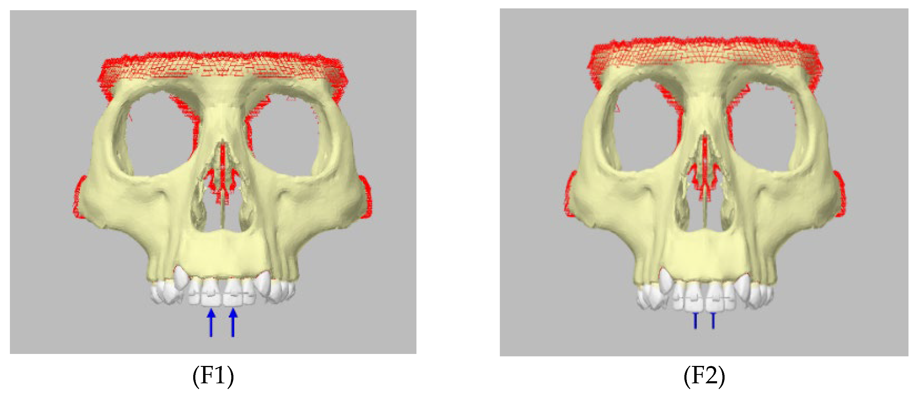
As the maximum occlusal load on incisors has been reported to range between 40 and 200 N [21], a concentrated load of 150 N was considered within physiologic limits and was applied vertically or obliquely in the simulations (Figure 3).
In the present study, four groups with different splinting extensions were created, including a control group. The control group consisted of teeth simulated without splinting (Figure 4).
Model 1: Composite Orthodontic Wire Splinted Tooth Model (M1)
Model 2: Titanium Trauma Splinted Tooth Model (M2)
Model 3: Nylon Fishing Line Applied Tooth Model (M3)
In cases where objects undergo multiaxial loading, the von Mises equivalent stress is commonly used to determine if plastic deformation occurs in the material. In this study, the regions and magnitudes of the highest stress and deformation in the teeth and supporting tissues were evaluated under vertical and oblique forces applied to upper jaw models with different splinting extensions and materials. Stress distribution and stress values were analyzed based on the von Mises stress criterion.
Only relative stress values could be obtained from the simulation software, and therefore absolute stress values were not available for presentation. While this limits comparison with other studies, relative values still allow for reliable intra-model comparison of different splint materials and lengths.

3. Results

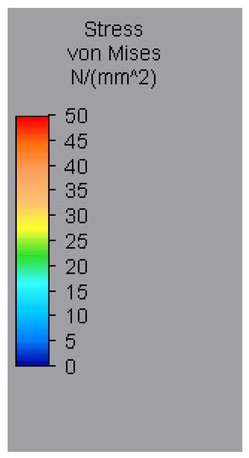
In the present study, the maximum von Mises stress values generated in the dental tissues under forces applied to the models at two different angles, designed to simulate masticatory loading, are shown in the following figures and graphs. The same loading conditions were applied at identical points to the tooth model, which served as the control group (Figure 5). In the figures, the color gradient from blue to red indicates (Figure 6) increasing von Mises stress values.

3.1. Von Mises Stress Values Formed in Models with Vertical Force Application

3.1.1. Enamel

A force of 150 N, parallel to the long axis of the tooth, was applied to the predetermined incisal points on the models. The maximum von Mises stress values in the enamel, dentin, and pulp (Figure 7) were assessed when vertical loading was applied to the composite orthodontic wire splinted tooth model (M1), the titanium trauma splinted tooth model (M2), and the nylon fishing line splinted tooth model (M3), each with different splinting extensions (lateral–lateral, first premolar–first premolar, first molar–first molar) (Figure 8, Figure 9 and Figure 10).
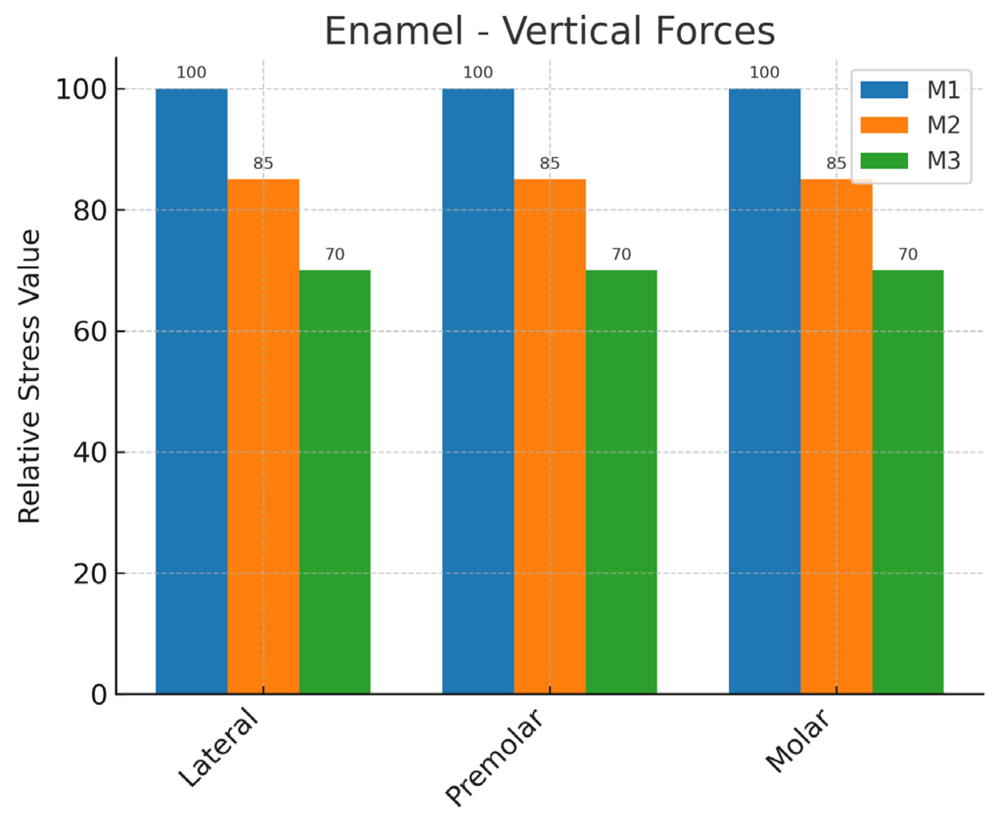
The highest stress in the enamel was observed in all the groups at the point where the force was applied. The stress amounts were measured as M1 > M2 > M3. Increasing the splint extension created extra stress in M1 and M2. M3 gave the closest result to the stress in the control group (Figure 11).

3.1.2. Dentin

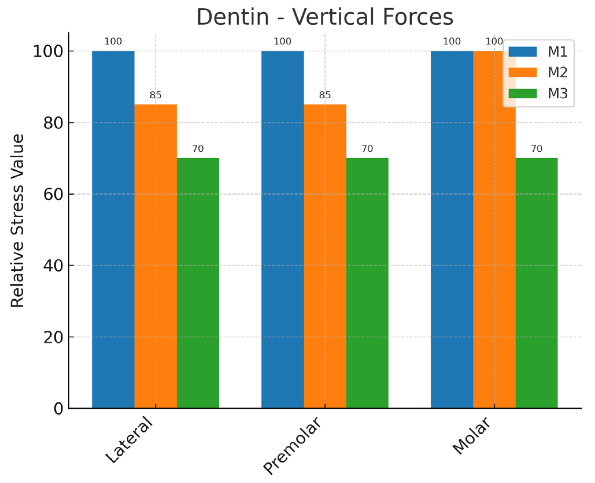
In dentin, the highest relative stress values were consistently seen in M1 across all splinting extensions, followed by M2 and M3 (Figure 12, Figure 13 and Figure 14). Extending the splint length did not significantly change the order of the models but caused a slight increase in stress for M1 and M2. M3 had the lowest stress values, staying closer to natural levels (Figure 15).

3.1.3. Pulp

When the stress distributions in the pulp as a result of the vertical force applied in all the groups were examined (Figure 16, Figure 17 and Figure 18), the highest stress was observed on the surfaces of the pulp facing the dentin. Similar results were obtained for the pulp in all splint models compared with the control model. When the splinting extension was increased, it was observed to be at a clinically acceptable value (Figure 19).
To simulate the bite force, a load of 150 N was applied to the predetermined palatal points on the models at a 45° angle to the long axis of the tooth (Figure 20). The maximum von Mises stress values in the enamel, dentin, and pulp were examined when oblique loading was applied to M1, M2, and M3, each with different splinting extensions (lateral to lateral, first premolar to first premolar, and first molar to first molar).

3.2. Von Mises Stress Values Formed in Models with Oblique Force Application

3.2.1. Enamel

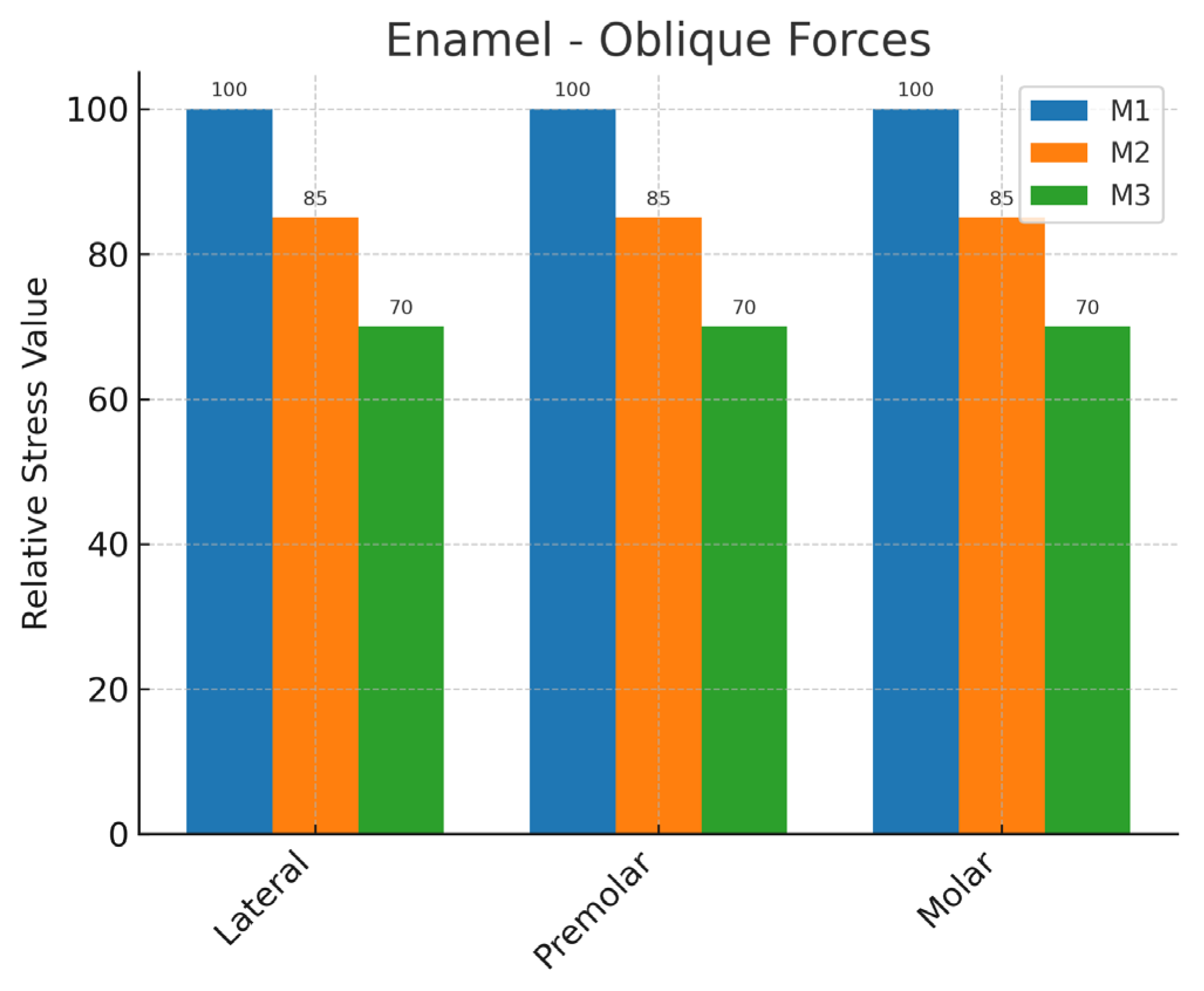
When the stress distributions in the enamel under oblique loading were examined across all groups, stress concentration was observed primarily in the cervical region. The stress magnitudes followed the order M1 ≥ M2 > M3 (Figure 21, Figure 22 and Figure 23). Among the models, M3 consistently demonstrated the lowest stress values, remaining closer to physiological conditions (Figure 24).

3.2.2. Dentin

When the stress distributions in the dentin under oblique loading were examined across all groups, the stress magnitude followed the order M1 ≥ M2 > M3 (Figure 25, Figure 26 and Figure 27). Increasing the splinting extension resulted in additional stress in the first molar region for M1 and M2, whereas no notable stress concentration was observed in M3 (Figure 28).

3.2.3. Pulp

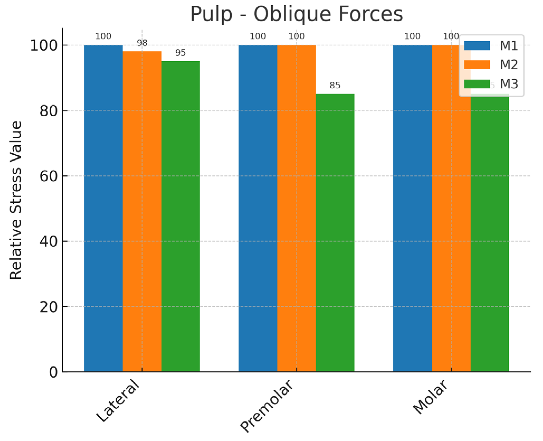
When the stress distributions in the pulp under oblique loading were examined in the lateral group, similar stress values were observed across the splint models. In the first premolar–first premolar and first molar–first molar groups, the stress magnitudes followed the order M1 ≥ M2 > M3 (Figure 29, Figure 30 and Figure 31). Increasing the splinting extension resulted in additional stress in M1 and M2 for the first premolar and first molar teeth, while no notable stress concentration was detected in M3 (Figure 32).

4. Discussion

Dental trauma is one of the most common problems in the pediatric population, second only to dental caries [22]. Incisors are affected in approximately 97% of cases, with reported trauma rates of 34% for the maxillary central incisors, 6% for the maxillary lateral incisors, 6% for the mandibular central incisors, and 3% for the mandibular lateral incisors [23]. In the present study, maxillary incisors were selected because they are the teeth most frequently exposed to trauma in their anatomical region. This selection also allowed for comparison with previous research findings. Given that the root apices were closed, endodontic treatment is often clinically indicated for such teeth. In these cases, the removal of pulp tissue and the presence, type, and spatial distribution of root canal filling materials, such as gutta-percha and sealer, may influence stress distribution. Although these factors were not included in the present finite element analysis, they may be incorporated into future modeling to provide a more comprehensive biomechanical assessment.
The incidence of complications increases significantly when dental trauma is not managed promptly. As the condition progresses, treatment becomes more complex and costly [24]. Successful management depends on the clinician’s experience and the correct selection and application of materials for an appropriate method and duration. Splints play a critical role in the treatment of dental trauma; however, prolonged splinting and the use of rigid materials may result in adverse outcomes such as external root resorption, replacement resorption (ankylosis), and eventual tooth loss [25]. Controlled tooth mobility within the traumatized socket is essential to facilitate periodontal healing, with movements in the range of approximately 10 to 100 µm considered safe and beneficial during splinting [26].
The materials used for splinting have evolved considerably over the years. Traditionally, rigid and long-term splinting methods using arch bars and ligature wires, initially developed for jaw fracture management, were also employed in the stabilization of traumatized teeth [27]. With the advancement of adhesive techniques, these approaches have been adapted for dental splinting, resulting in materials and methods that permit physiological tooth movement without compromising stability [28].
In line with these developments, recent research has increasingly focused on evaluating the clinical and biomechanical performance of modern splinting systems compared with traditional approaches. Dental trauma splints have been extensively studied. In their comparative study on splint materials, Sobczak-Zagalska and Emerich [29] evaluated titanium trauma splints, wire composite splints, and power chain composite splints. The most favorable outcome was achieved with the power chain composite splint, followed by the titanium trauma splint.
In the present study, both modern and traditional splint types currently used in clinical practice were evaluated for their ability to stabilize teeth and promote healing following dental trauma. The stress distributions generated by titanium trauma splints (TTS) and nylon fishing line splints—both favored in recent years—were compared with those produced by traditionally used wire composite splints. The analysis focused on the teeth and surrounding supporting tissues under simulated masticatory forces using the finite element method.
The finite element analysis (FEA) method offers several advantages, including the ability to model objects with complex geometry, represent their mechanical and physical properties with high accuracy, generate multiple models incorporating different materials in a computer environment, measure stress distributions and displacements precisely, and readily modify applied forces or geometric parameters [30]. The reliability of results obtained from FEA depends heavily on the accurate definition of material properties; incorrect or imprecise input data will inevitably lead to inaccurate outcomes. Given the complexity of the anatomy and mechanical behavior of human tissues, modeling them is challenging, and the validity of the conclusions also depends on the expertise of the individual interpreting the results [31]. Moreover, a major limitation of FEA is the oversimplification of biological tissues, which are commonly assumed to be homogeneous, isotropic, and linearly elastic. The periodontal ligament exhibits nonlinear and viscoelastic behavior, and alveolar bone presents anisotropic characteristics, as highlighted in previous biomechanical studies. These simplifications may have influenced the stress distribution patterns in the present study and should be considered when interpreting the findings.
Liu et al. [31] evaluated splint materials using FEA with a loading force of 100 N. Poiate et al. [6] examined the effects of masticatory, parafunctional, and traumatic forces on periodontal tissues using three-dimensional FEA, identifying 150 N as the chewing force, 500 N as the parafunctional force, and 1000 N as the traumatic force. In accordance with the literature, the present study applied a 150 N load vertically and obliquely. As described in the Methods, a 150 N load was applied vertically and obliquely to simulate physiologic masticatory forces. Under these conditions, the nylon fishing line splint produced stress distributions closer to natural physiology, while the composite orthodontic wire splint exhibited higher stress accumulation.
The creation of four different splinting groups, including a control group, enabled direct comparison between traditional and modern splint types. This design revealed that nylon fishing line splints demonstrated more favorable biomechanical behavior compared to composite orthodontic wire splints.
In the study by Fidancıoğlu [32] evaluating splint materials with FEA, composite splints, composite orthodontic wire splints, titanium trauma splints, and fiber splints were compared. Under both vertical and oblique loading, the composite splint yielded the least favorable results across all tissues, followed by the composite orthodontic wire splint. The most favorable outcomes were achieved with the fiber splint and the titanium trauma splint. In contrast, in the present study, the nylon fishing line splint (M3) produced the most favorable results under both vertical and oblique loading, whereas the composite orthodontic wire splint (M1) was the least successful.
Vilela et al. [33] used FEA to investigate nylon fishing line splints and composite orthodontic wire splints with varying splinting extensions. They reported that increasing the splint extension in the nylon fishing line splint did not affect tooth mobility, while in composite orthodontic wire splints, greater splint extension reduced tooth mobility but increased stress on the teeth. Consistent with these findings, the present study observed that increasing splint extension did not influence tooth stress in the nylon fishing line splint (M3), whereas additional stress was generated in the composite orthodontic wire splint (M1) and the titanium trauma splint (M2).
One limitation of the present study is the omission of the fiber splint, which is among the contemporary splint materials currently in use. Furthermore, the effect of the bonding material on traumatized and splinted teeth warrants investigation in future research. Based on the findings of this study, the H0 hypothesis was rejected. Both the splint material and the splint length were found to influence stress accumulation in the tooth and surrounding supporting tissues. The periodontal ligament (PDL) and alveolar bone were included in the finite element model; however, their results were not analyzed in detail, as the focus of the study was on the stress distribution in the splinted teeth. This simplification may affect the accuracy of stress distribution and restricts the direct extrapolation of the findings to clinical conditions. Also, the control group results could not be graphically presented due to software and data export restrictions. Although this prevented visual comparison, the control group was used as the baseline reference during analysis and considered in the interpretation of the findings.
This study contributes to the existing body of knowledge by comparing modern and traditional splinting materials using a finite element approach under clinically relevant loads in the early permanent dentition stage. The results show that splint flexibility and extension greatly affect stress distribution in the tooth and supporting tissues, with nylon fishing line splints exhibiting biomechanical behavior closer to natural conditions compared to more rigid options. Although excluding fiber splints is a limitation, the findings emphasize the importance of choosing the right material and splint design to improve healing after dental trauma. Future studies, including various splint types, bonding materials, and patient-specific models, will help refine clinical trauma management protocols.
This study has some limitations. The relatively small sample size restricts the generalizability of the findings. Additionally, the research was conducted under controlled experimental conditions, which may not accurately reflect real clinical situations. Furthermore, the long-term outcomes of the splints were not evaluated. Therefore, further studies with larger sample sizes, different clinical settings, and extended follow-up periods are needed to validate and expand upon these findings.

5. Conclusions

The finite element analysis demonstrated that both splint type and splint length have a significant impact on stress distribution in early permanent dentition. As only relative stress values were obtainable, our findings are limited to intra-model comparisons rather than absolute values. Nonetheless, this approach reliably demonstrated differences among splint materials under comparable conditions.
Among the evaluated models, the nylon fishing line splint exhibited biomechanical behavior closer to physiological conditions, generating lower stress values in the tooth and supporting tissues compared with more rigid alternatives. These findings may help clinicians select splinting strategies that optimize periodontal healing and reduce the risk of complications in pediatric dental trauma cases.

Author Contributions

Conceptualization: S.B.Z.; Methodology: S.B.Z. and F.K.; Software: S.B.Z.; Validation: S.B.Z.; Investigation: S.B.Z. and F.K.; Resources: S.B.Z.; Data curation: S.B.Z. and F.K.; Writing—original draft preparation: S.B.Z. and F.K.; Writing—review and editing: S.B.Z. and F.K.; Visualization: S.B.Z. All authors have read and agreed to the published version of the manuscript.

Funding

This study was supported by the Selcuk University Scientific Research Projects Unit Türkiye, grant Number 23132021.

Institutional Review Board Statement

Ethical approval for the study protocol was obtained from the Selcuk University ethics committee (approval no: 2023/39). The study was carried out in accordance with the Declaration of Helsinki guidelines. Ethical approval was obtained from the Selcuk University Health Sciences Non-Interventional Clinical Research Ethics Committee with the decision numbered 2023/39. This study was conducted in collaboration between the Faculty of Dentistry at Selcuk University and Ay Tasarım Limited Company. It investigated the stress accumulation and distribution associated with three different splint types and material lengths in the teeth and surrounding tissues during the mixed dentition period. Static linear analysis was performed using the three-dimensional finite element stress analysis method. Dental tomography images from an 11-year-old female patient in the mixed dentition stage were utilized. No additional imaging was requested for the purposes of this study. Instead, previously acquired tomography scans, originally taken for orthodontic evaluation and diagnostic purposes, were reviewed. The patient’s computed tomography images, stored in DICOM format, had been obtained at the Department of Oral, Dental, and Maxillofacial Radiology, Faculty of Dentistry, Selcuk University, using an Orthopantomograph OP300 (Instrumentarium) unit. Care was taken to ensure that the maxillary incisor, first premolar, and first molar designated for splinting were intact, without impaction or absence, in the selected images.

Informed Consent Statement

Written informed consent was obtained from the patient’s legal guardian, as the patient was under the age of 18, for the publication of this article.

Data Availability Statement

The datasets and materials used or analyzed during the current study are available from the corresponding author upon reasonable request.

Acknowledgments

The authors would like to thank Ay Tasarım Limited Company for their valuable support during the finite element analysis.

Conflicts of Interest

The authors declare no competing interests.

Abbreviations

The following abbreviations are used in this manuscript:
FEAFinite Element Analysis
DICOMDigital Imaging and Communications in Medicine
EEnamel
DDentin
PPulp
CGControl Group
M1Model 1
M2Model 2
M3Model 3
M1Composite Orthodontic Wire Splinted Tooth Model
M2Titanium Trauma Splinted Tooth Model
M3Nylon Wire Splinted Tooth Model

References

  1. Glendor, U.L.F. Epidemiology of traumatic dental injuries—A 12-year review of the literature. Dent. Traumatol. 2008, 24, 603–611. [Google Scholar] [CrossRef]
  2. Kahler, B.; Hu, J.Y.; Marriot-Smith, C.S.; Heithersay, G.S. Splinting of teeth following trauma: A review and a new splinting recommendation. Aust. Dent. J. 2016, 61, 59–73. [Google Scholar] [CrossRef]
  3. Trope, M. Avulsion of permanent teeth: Theory to practice. Dent. Traumatol. 2011, 27, 281–294. [Google Scholar] [CrossRef]
  4. Andersson, L. Traumatic dental injuries. In Oral and Maxillofacial Surgery; John Wiley & Sons: New York, NY, USA, 2025; pp. 751–771. [Google Scholar]
  5. Burcak Cengiz, S.; Stephan Atac, A.; Cehreli, Z.C. Biomechanical effects of splint types on traumatized tooth: A photoelastic stress analysis. Dent. Traumatol. 2006, 22, 133–138. [Google Scholar] [CrossRef]
  6. Poiate, I.A.V.P.; De Vasconcellos, A.B.; De Santana, R.B.; Poiate, E., Jr. Three-dimensional stress distribution in the human periodontal ligament in masticatory, parafunctional, and trauma loads: Finite element analysis. J. Periodontol. 2009, 80, 1859–1867. [Google Scholar] [CrossRef]
  7. Belevcikli, M.; Altan, H.; Altan, A. Surgical extrusion of anterior teeth with intrusion traumatic injury: A report of two cases. Eur. Endod. J. 2020, 5, 295. [Google Scholar] [CrossRef]
  8. Kwan, S.C.; Johnson, J.D.; Cohenca, N. The effect of splint material and thickness on tooth mobility after extraction and replantation using a human cadaveric model. Dent. Traumatol. 2012, 28, 277–281. [Google Scholar] [CrossRef]
  9. Güngör, M.A.; Artunc, C.; Sonugelen, M.; Toparli, M. The evaluation of the removal forces on the conus crowned telescopic prostheses with the finite element analysis (FEA). J. Oral Rehabil. 2002, 29, 1069–1075. [Google Scholar] [CrossRef] [PubMed]
  10. Vilela, A.B.; Soares, P.B.; Almeida, G.A.; Veríssimo, C.; Rodrigues, M.P.; Versluis, A.; Soares, C.J. Three-dimensional finite element stress analysis of teeth adjacent to a traumatized incisor. Dent. Traumatol. 2019, 35, 128–134. [Google Scholar] [CrossRef] [PubMed]
  11. Huang, H.M.; Ou, K.L.; Wang, W.N.; Chiu, W.T.; Lin, C.T.; Lee, S.Y. Dynamic finite element analysis of the human maxillary incisor under impact loading in various directions. J. Endod. 2005, 31, 723–727. [Google Scholar] [CrossRef] [PubMed]
  12. Giesen, E.B.; Ding, M.; Dalstra, M.; van Eijden, T.M. Mechanical properties of cancellous bone in human mandibular condyle are anisotropic. J. Biomech. 2001, 34, 799–803. [Google Scholar] [CrossRef]
  13. Lettry, S.; Seedhom, B.B.; Berry, E.; Cuppone, M. Quality assessment of the cortical bone of the human mandible. Bone 2003, 32, 35–44. [Google Scholar] [CrossRef]
  14. Gurbuz, T.; Sengul, F.; Altun, C. Finite element stress analysis of short-post core and over restorations prepared with different restorative materials. Dent. Mater. J. 2008, 27, 499–507. [Google Scholar] [CrossRef]
  15. Sumanariu, C.A.; Amza, C.G.; Baciu, F.; Vasile, M.I.; Nicoara, A.I. Comparative Analysis of Mechanical Properties: Conventional vs. Additive Manufacturing for Stainless Steel 316L. Materials 2024, 17, 4808. [Google Scholar] [CrossRef]
  16. Elias, C.N.; Lima, J.H.C.; Valiev, R.; Meyers, M.A. Biomedical applications of titanium and its alloys. JOM 2008, 60, 46–49. [Google Scholar] [CrossRef]
  17. Da Silva, L.A.B.; Nelson-Filho, P.; da Silva, R.A.B.; Flores, D.S.H.; Heilborn, C.; Johnson, J.D.; Cohenca, N. Revascularization and periapical repair after endodontic treatment using apical negative pressure irrigation versus conventional irrigation plus triantibiotic intracanal dressing in dogs’ teeth with apical periodontitis. Oral Surg. Oral Med. Oral Pathol. Oral Radiol. Endodontology 2010, 109, 779–787. [Google Scholar] [CrossRef]
  18. Gupta, M.; Madhok, K.; Kulshrestha, R.; Chain, S.; Kaur, H.; Yadav, A. Determination of stress distribution on periodontal ligament and alveolar bone by various tooth movements—A 3D FEM study. J. Oral Biol. Craniofacial Res. 2020, 10, 758–763. [Google Scholar] [CrossRef] [PubMed]
  19. Aykaç, V.; Ulusoy, Ç.; Türköz, Ç. Effects of a newly designed orthodontic miniplate platform for elevating the miniplate over the gingiva: A 3-dimensional finite element analysis. Am. J. Orthod. Dentofac. Orthop. 2015, 148, 110–122. [Google Scholar] [CrossRef]
  20. Pari, A.; Ilango, P.; Subbareddy, V.; Katamreddy, V.; Parthasarthy, H. Gingival diseases in childhood—A review. J. Clin. Diagn. Res. JCDR 2014, 8, ZE01. [Google Scholar] [CrossRef]
  21. Hellsing, G. On the Regulation of Interincisor Bite Force in Man. J. Oral Rehabil. 1980, 7, 403–411. [Google Scholar] [CrossRef] [PubMed]
  22. Saikiran, K.V.; Gurunathan, D.; Nuvvula, S.; Jadadoddi, R.K.; Kumar, R.H.; Birapu, U.C. Prevalence of Dental Trauma and Their Relationship to Risk Factors among 8–15-Year-Old School Children. Int. J. Dent. 2022, 2022, 3343827. [Google Scholar] [CrossRef]
  23. Skaare, A.B.; Jacobsen, I. Dental injuries in Norwegians aged 7–18 years. Dent. Traumatol. 2003, 19, 67–71. [Google Scholar] [CrossRef] [PubMed]
  24. Altun, C.; Cehreli, Z.C.; Güven, G.; Acikel, C. Traumatic intrusion of primary teeth and its effects on the permanent successors: A clinical follow-up study. Oral Surg. Oral Med. Oral Pathol. Oral Radiol. Endodontology 2009, 107, 493–498. [Google Scholar] [CrossRef] [PubMed]
  25. de Andrade Veras, S.R.; Bem, J.S.P.; de Almeida, E.C.B.; Lins, A. Dental splints: Types and time of immobilization post tooth avulsion. J. Istanb. Univ. Fac. Dent. 2017, 51 (Suppl. 1), S69–S75. [Google Scholar] [CrossRef]
  26. Boldt, J.; Knapp, W.; Proff, P.; Rottner, K.; Richter, E.J. Measurement of tooth and implant mobility under physiological loading conditions. Ann. Anat.-Anat. Anz. 2012, 194, 185–189. [Google Scholar] [CrossRef] [PubMed]
  27. Kehoe, J.C. Splinting and replantation after traumatic avulsion. J. Am. Dent. Assoc. 1986, 112, 224–230. [Google Scholar] [CrossRef]
  28. Berthold, C.; Thaler, A.; Petschelt, A. Rigidity of commonly used dental trauma splints. Dent. Traumatol. 2009, 25, 248–255. [Google Scholar] [CrossRef]
  29. Sobczak-Zagalska, H.; Emerich, K. Assessment of a power chain as a new dental trauma splint and its comparison with two commonly used splinting materials. Appl. Sci. 2020, 10, 8398. [Google Scholar] [CrossRef]
  30. Rieger, M.R.; Mayberry, M.; Brose, M.O. Finite element analysis of six endosseous implants. J. Prosthet. Dent. 1990, 63, 671–676. [Google Scholar] [CrossRef]
  31. Liu, Y.; Fang, M.; Zhao, R.; Liu, H.; Tian, M.; Zhong, S.; Bai, S. Effects of periodontal splints on biomechanical behaviors in compromised periodontal tissues and cement layer: 3D finite element analysis. Polymers 2022, 14, 2835. [Google Scholar] [CrossRef]
  32. Fidancıoğlu, Y.D. Evaluation of Stress Distributions Created by Different Splint Types Applied to Traumatized Teeth Using Finite Element Analysis. Ph.D. Thesis, Necmettin Erbakan University, Konya, Turkey, 2020. [Google Scholar]
  33. Vilela, A.B.F.; Soares, P.B.F.; Versluis, A.; Soares, C.J. Dental trauma splints for the mixed dentition–a finite element analysis of splint material, splint extension, missing teeth, and PDL representation. Dent. Traumatol. 2022, 38, 495–504. [Google Scholar] [CrossRef] [PubMed]
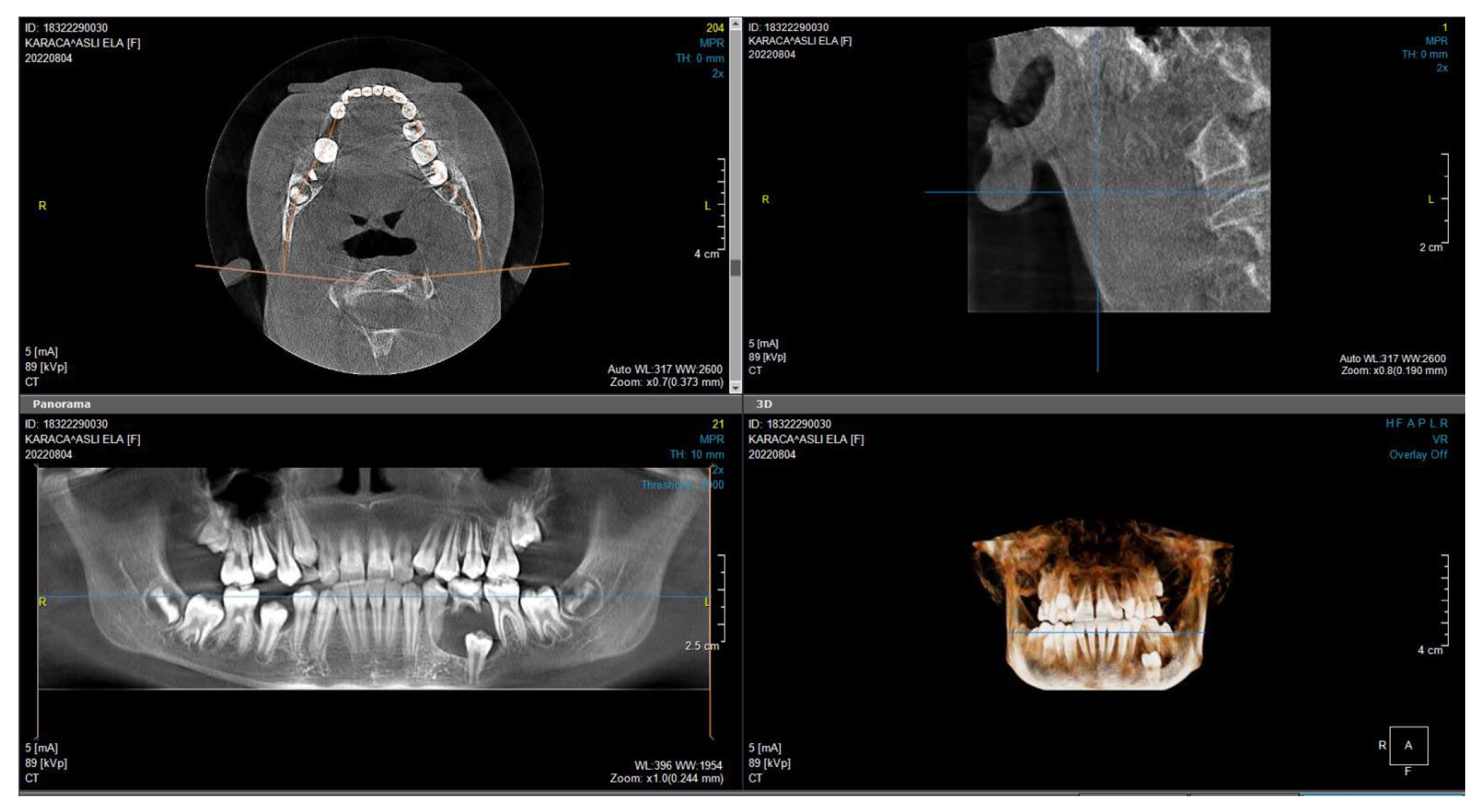
Figure 1. Computed tomography image used as the basis for model construction.
Applsci 15 10307 g001
Figure 2. Three-dimensional solid model of the maxilla (M) and teeth (T) generated from computed tomography images through meshing.
Applsci 15 10307 g002
Figure 3. Vertical force direction (F1) applied at a 90° angle from the middle of the incisal edge, and oblique force direction (F2) applied at a 45° angle to the long axis of the tooth.
Applsci 15 10307 g003
Figure 4. Meshed models M1, M2, M3.
Applsci 15 10307 g004
Figure 5. Control Group (M1) Enamel, (M2) Dentin and (M3) Pulp.
Applsci 15 10307 g005
Figure 6. Color and value scale.
Applsci 15 10307 g006
Figure 7. Distributions of von Mises stresses in the enamel (E), dentin (D), and pulp (P) of the CG model under vertical forces.
Applsci 15 10307 g007
Figure 8. Distributions of von Mises stresses occurring in enamel in the lateral-lateral group under vertical forces in M1, M2 and M3.
Applsci 15 10307 g008
Figure 9. Distributions of von Mises stresses occurring in enamel in the 1st premolar-1st premolar group under vertical forces in M1, M2 and M3.
Applsci 15 10307 g009
Figure 10. Distributions of von Mises stresses occurring in enamel in the 1st molar-1st molar group under vertical forces in M1, M2 and M3.
Applsci 15 10307 g010
Figure 11. The graphical analysis of the data, allowing a comparative evaluation of the measured stress distributions across the different groups (lateral, premolar, and molar).
Applsci 15 10307 g011
Figure 12. Distributions of von Mises stresses occurring in dentin in the lateral-lateral group under vertical forces in M1, M2, and M3.
Applsci 15 10307 g012
Figure 13. Distributions of von Mises stresses occurring in dentin in the 1st premolar-1st premolar group under vertical forces in M1, M2, and M3.
Applsci 15 10307 g013
Figure 14. Distributions of von Mises stresses occurring in dentin in the 1st molar-1st molar group under vertical forces in M1, M2, and M3.
Applsci 15 10307 g014
Figure 15. The graphical analysis of the data, allowing a comparative evaluation of the measured stress distributions across the different groups (lateral, premolar, and molar).
Applsci 15 10307 g015
Figure 16. Distributions of von Mises stresses occurring in pulp in the lateral-lateral group under vertical forces in M1, M2, and M3.
Applsci 15 10307 g016
Figure 17. Distributions of von Mises stresses occurring in pulp in the 1st premolar-1st premolar group under vertical forces in M1, M2, and M3.
Applsci 15 10307 g017
Figure 18. Distributions of von Mises stresses occurring in pulp in the 1st molar-1st molar group under vertical forces in M1, M2, and M3.
Applsci 15 10307 g018
Figure 19. The graphical analysis of the data, allowing a comparative evaluation of the measured stress distributions across the different groups (lateral, premolar, and molar).
Applsci 15 10307 g019
Figure 20. Distributions of von Mises stresses in E, D, and P of the CG model under oblique forces.
Applsci 15 10307 g020
Figure 21. Distributions of von Mises stresses occurring in enamel in the lateral-lateral group under oblique forces in M1, M2, and M3.
Applsci 15 10307 g021
Figure 22. Distributions of von Mises stresses occurring in enamel in the first premolar-first premolar group under oblique forces in M1, M2, and M3.
Applsci 15 10307 g022
Figure 23. Distributions of von Mises stresses occurring in enamel in the first molar-first molar group under oblique forces in M1, M2, and M3.
Applsci 15 10307 g023
Figure 24. The graphical analysis of the data, allowing a comparative evaluation of the measured stress distributions across the different groups (lateral, premolar, and molar).
Applsci 15 10307 g024
Figure 25. Distributions of von Mises stresses occurring in dentin in the lateral-lateral group under oblique forces in M1, M2, and M3.
Applsci 15 10307 g025
Figure 26. Distributions of von Mises stresses occurring in dentin in the first premolar-first premolar group under oblique forces in M1, M2, and M3.
Applsci 15 10307 g026
Figure 27. Distributions of von Mises stresses occurring in dentin in the first molar-first molar group under oblique forces in M1, M2, and M3.
Applsci 15 10307 g027
Figure 28. The graphical analysis of the data, allowing a comparative evaluation of the measured stress distributions across the different groups (lateral, premolar, and molar).
Applsci 15 10307 g028
Figure 29. Distributions of von Mises stresses occurring in pulp in the lateral-lateral group under oblique forces in M1, M2, and M3.
Applsci 15 10307 g029
Figure 30. Distributions of von Mises stresses occurring in pulp in the first premolar-first premolar group under oblique forces in M1, M2, and M3.
Applsci 15 10307 g030
Figure 31. Distributions of von Mises stresses occurring in pulp in the first molar-first molar group under oblique forces in M1, M2, and M3.
Applsci 15 10307 g031
Figure 32. Figure 29, Figure 30 and Figure 31 present the graphical analysis of the data, allowing a comparative evaluation of the measured stress distributions across the different groups.
Applsci 15 10307 g032
Table 1. Number of elements and nodes in the models used in the present study.
ElementsNodes
Control Group2,677,417494,570
Lateral2,685,356496,873
First Premolar2,688,950498,172
First Molar499,799500,799
Table 2. Elastic modulus and Poisson’s ratios of dental tissues, supporting structures, and splint materials.
MaterialsElastic Modulus (MPa)Poisson’s Ratio (µ)Reference
Enamel77,9000.33[11]
Dentin16,6000.41[11]
Pulp6.990.45[11]
PDL500.45[11]
Trabecular Bone4310.30[12]
Cortical Bone11,5000.30[13]
Composite10,0000.24[14]
Stainless Steel Wire200,0000.30[15]
Titanium110,0000.34[16]
Nylon Fishing Line27000.3[14]
Disclaimer/Publisher’s Note: The statements, opinions and data contained in all publications are solely those of the individual author(s) and contributor(s) and not of MDPI and/or the editor(s). MDPI and/or the editor(s) disclaim responsibility for any injury to people or property resulting from any ideas, methods, instructions or products referred to in the content.