Abstract
This work evaluates a hydrogen-fueled planar micro-combustor featuring three triply periodic minimal surface (TPMS) structures, namely, gyroid, lidinoid, and Neovius matrix lattices, aiming to advance heat transfer processes and enhance system efficiency in micro-thermophotovoltaic (MTPV) applications. Through three-dimensional numerical investigations, a series of simulations are conducted under varying TPMS lengths, inlet volume flow rate, and inlet equivalence ratios to optimize the design and operating conditions. The outcomes reveal that increasing the length of the TPMS structures is an effective means of improving heat transfer from the combustion zone to the walls, as indicated by significant increases in both mean wall temperature and radiation efficiency. However, longer internal structures reduce the uniformity of wall temperature and slightly increase entropy generation. Of the three topologies, the Neovius lattice demonstrates superior performance in all length scales, exhibiting a marginal improvement over the gyroid and a substantially greater advantage over the lidinoid structure. Increasing the inlet volume flow rate enhances wall temperature and its uniformity; however, the performance parameters decrease for all structures, indicating a limitation of the micro-combustor in benefiting from higher input power. Notably, the gyroid structure shows a lower rate of performance degradation at higher velocities, making it a potentially ideal design under such conditions. Finally, varying the equivalence ratio identifies the stoichiometric condition as optimal, yielding superior performance metrics compared to both lean and rich mixtures.
1. Introduction
Recently, micro-electro-mechanical systems (MEMSs) have been extensively investigated for their role in developing miniaturized and intelligent technologies, with applications spanning power generation, biomedicine, and other sectors [1,2]. Within this domain of micro-scale applications, micro-thermophotovoltaic (MTPV) technology, which is based on micro-combustion, serves as an energy supply unit by converting chemical energy into electrical power. The main component of an MTPV system is the micro-combustor, which is characterized by its small size, simple structure, and high energy density [3,4]. However, the compact design of the micro-combustor leads to unstable combustion due to short dwell time and a high heat-loss-to-generation ratio [5,6,7].
Notable efforts have been made by researchers to address these challenges by implementing various combustion approaches, such as non-premixed combustion [8,9] and dilution combustion [10]. Furthermore, over the past few years, the proposal of new design configurations has become an active research field to improve the key thermal and performance characteristics of micro-combustors. For example, Yao et al. [11] investigated the effects of a hydrogen-fueled micro-combustor with a sinusoidal wall geometry on flame stability and thermal performance. The results indicated that incorporating a sinusoidal wall geometry generates a flow return structure, thereby enhancing flame anchoring effects. As highlighted, the aspect ratio of 5π/7 demonstrates the best thermal performance, extending the blowout limit by a factor of two compared with the 5π/3 configuration. Sun et al. [12] examined the effects of a micro-combustor with an opposed-flow inlet on thermal and emission parameters. The findings revealed that the opposed-inlet design deflects the incoming flow by 90°, creating a stagnation plane that stabilizes the flame and restricts its propagation toward the outlet. Compared with the traditional design, this configuration improves the mean wall temperature, mean wall temperature uniformity, and radiation efficiency by 125.4 K, 12%, and 5.4%, respectively. In addition to these investigations, many other proposed designs for micro-combustors can be found in the literature such as [13,14,15,16,17].
The key pillar for achieving further improvements in the overall efficiency of MTPV systems lies in enhancing the heat transfer mechanisms within the micro-combustor, particularly the transfer of thermal energy released during combustion to the external walls, to ensure greater radiative energy emission toward the PV cell, thereby generating more electricity. In recent years, the literature has been enriched with numerous new structural designs in heat exchanger applications, contributing to the rapid development of this field. One concept that has proven effective in improving heat transfer in heat exchangers is the triply periodic minimal surface (TPMS), which refers to surfaces that repeat periodically in all three spatial dimensions and exhibit zero mean curvature. TPMS lattices are characterized by high surface area, improved thermal management, scalability, and exceptional mechanical properties [18,19]. These advantages suggest that incorporating TPMS configurations into micro-combustors could support continued advancement of MTPV systems. For instance, integrating TPMS topologies into micro-combustors increases surface area and, consequently, residence time, enabling the external walls to absorb more thermal energy. There are common TPMS geometries, including the gyroid, lidinoid, and Neovius structures.
Various investigations have been conducted to reveal the impacts of gyroid structures on the heat transfer process in heat exchanger applications. Dixit et al. [20] investigated the thermal characteristics of a liquid–liquid micro-architected heat exchanger featuring a gyroid lattice. The authors reported that the gyroid structure increased the heat exchanger’s effectiveness by 55%, with an overall heat transfer coefficient ranging from 120−160 W/m2·K. Kus et al. [21] performed both experimental and numerical analyses to evaluate the impact of inserting a gyroid configuration in a heat exchanger. The results revealed that the gyroid heat exchanger achieves a 10.5% higher number of transfer units and approximately 5% greater temperature effectiveness than a plate heat exchanger 30% larger in size. Barakat et al. [22] numerically investigated the convective heat transfer performance of gyroid and diamond design configurations embedded within a heat exchanger. The study showed that the gyroid and diamond geometries enhance the heat transfer mechanism by 33% and 3.4%, respectively, and increase the Nusselt number by 23.7% and 10.4%. Kerme et al. [23] experimentally examined the impacts of porosity and cell size on the thermal performance of gyroid-based heat exchangers. The findings revealed that all gyroid structures, regardless of cell size and porosity, produce a more uniform temperature distribution, which disrupts the thermal boundary layer and thereby improves the transfer of thermal energy. However, minimizing the cell size in gyroid lattice yields a 51.5% greater coefficient of convective heat transfer in comparison with the other test cases.
In addition to the gyroid design, the lidinoid lattice structure is considered a promising alternative to conventional heat exchanger designs. Gado et al. [24] examined the impact of incorporating various TPMS-based configurations on the performance of adsorption cooling systems. Their study reported that the lidinoid design effectively increases the specific cooling power by 17.5% compared to a traditional fin-based structure. Padrão et al. [25] examined the effects of implementing surface-based lattices on fluid flow and conjugate heat transfer. Their findings indicated that the lidinoid structure at relatively low volume fractions achieves the highest volumetric heat transfer coefficients from 7.25 × 10⁴ W m−3 K−1 to 19.6 × 10⁴ W m−3 K−1. Furthermore, another investigation highlighted that the lidinoid design is conducive to improving the heat transfer process and Nusselt number compared to those of gyroid and diamond at the expense of a high pressure drop [26].
On the other hand, the Neovius lattice has attracted attention from researchers for its potential to enhance key thermal parameters. Wang et al. [27] examined the performance of heat exchangers incorporating different surface-based heat transfer channels at various volume fractions. The study found that using the Neovius lattice improves convective heat transfer due to enhanced secondary flow and velocity periodicity. Compared to other TPMS designs, the Neovius configuration demonstrates notable improvements in fluid mixing and flow routing, a moderate enhancement in heat transfer performance, and a relatively high friction factor [22,28,29].
The investigations outlined above, combined with numerous other studies [30,31,32,33,34], have demonstrated the potential of TPMS-based topologies to improve key thermal performance metrics due to their ability to increase surface area and enhance flow characteristics. Based on this, the integration of such structures into micro-combustors offers a promising solution to challenges such as short flow residence time, thereby contributing significantly to advancements in miniaturization and power generation technologies. It is important to note that the compact characteristic length of micro-combustors presents a barrier to the integration of TPMS configurations using conventional manufacturing methods. However, three-dimensional additive manufacturing techniques have demonstrated the capability to fabricate such complex geometries at the micro-scale [35]. To the best of the author’s knowledge, there is a lack of research in the existing literature on the influence of TPMS structures on the output energy of micro-combustors. Therefore, this numerical study aims to assess key thermal parameters, system efficiencies, and flow dynamics of three TPMS configurations—namely, gyroid, lidinoid, and Neovius matrix lattices—embedded within a hydrogen-fueled micro-combustor. In addition, this paper intends to optimize the system efficiency of the micro-combustor by means of conducting a parametric study, including the length of TPMS structures, inlet volume flow rate, and equivalence ratio. Section 2 introduces the physical model, governing equations, and boundary conditions employed in this study. A mesh sensitivity analysis and numerical model validation are also provided. Section 3 discusses the effects of the gyroid, lidinoid, and Neovius structures on thermal and performance parameters under varying the length of TPMS configurations, inlet velocities, and equivalence ratios. Section 4 summarizes the main outcomes of the work.
2. Numerical Methodology
2.1. Geometric Model
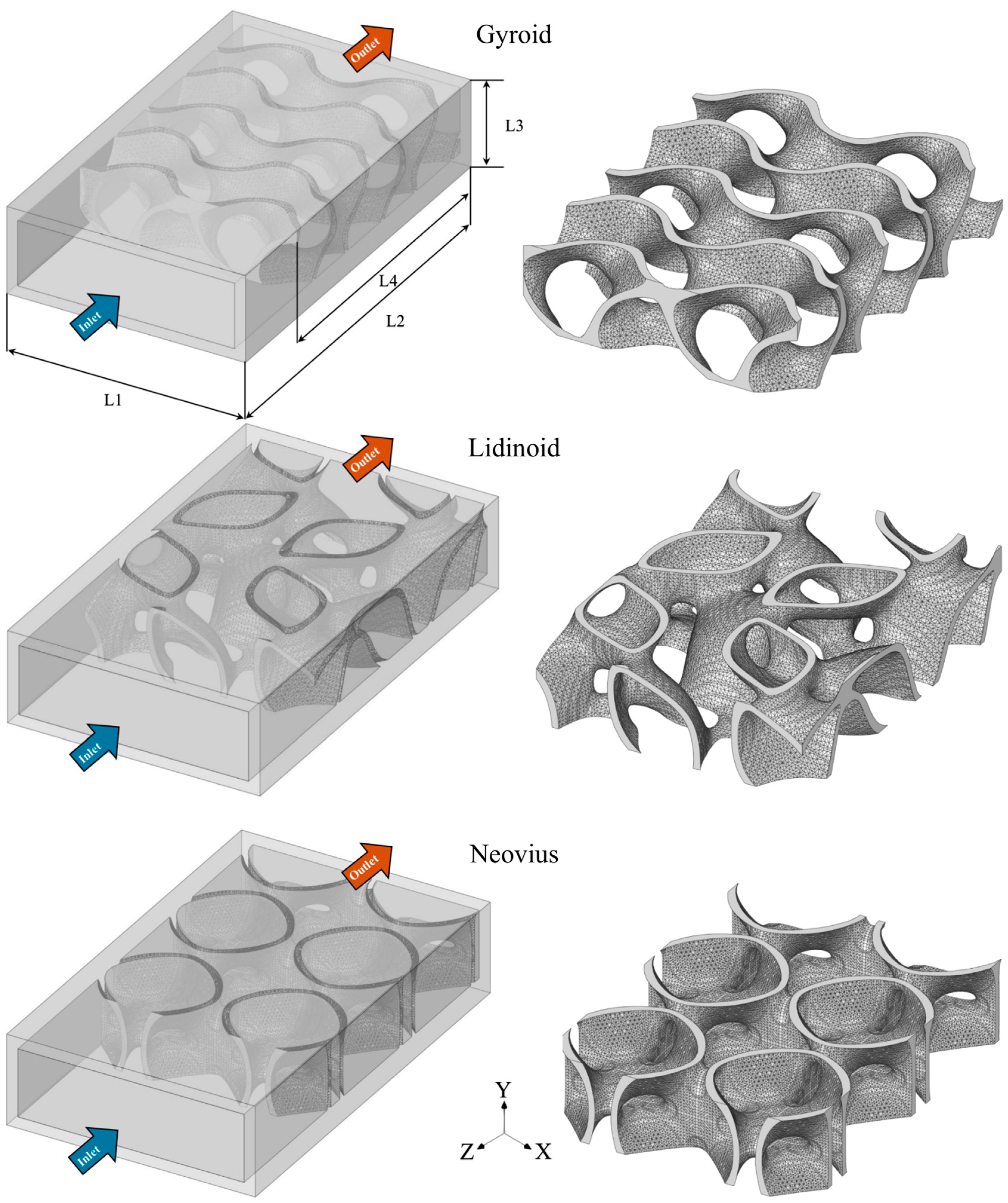
The micro-combustors featuring gyroid, lidinoid, and Neovius configurations, as illustrated in Figure 1, are modeled using ANSYS SpaceClaim R2 2023. The dimensions, surface areas, and porosity of all structures are listed in Table 1. In all cases, the micro-combustor has a width (L1) of 11 mm, a length (L2) of 18 mm, and a height (L3) of 4 mm, with an external wall thickness of 0.5 mm. The TPMS geometry dimensions are 10 mm in the x-direction and 3 mm in the y-direction, while three different lengths (L4)—5 mm, 9 mm, and 13 mm—are used in the z-direction to study the impacts of geometry length on performance and thermal parameters. The thickness of TPMS topologies is 0.25 mm. In general, each TPMS type is identified by its own mathematical formula that characterizes its structure. The implicit mathematical expressions of TPMS designs used in this study are as follows [28,36]:
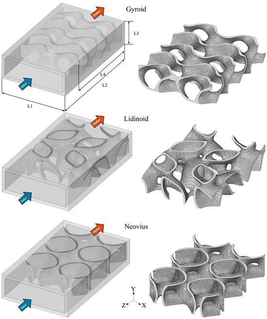
Figure 1.
The layout of the gyroid, lidinoid, and Neovius configurations embedded within the micro-combustor. L stands for length.

Table 1.
Dimensions of all test cases of this investigation. * The values represent the surface area and porosity of TPMS structures.
Gyroid:
Lidinoid:
Neovius:
2.2. Governing Equations
This numerical work is conducted with the aid of ANSYS Fluent R2 2023 [37]. Due to the low Mach number and a Reynolds number below 500, the flow is assumed to be incompressible and laminar, respectively [38,39]. In addition, the surface reactions, gravity, and Dufour effect are not accounted for in the simulations due to their negligible effects [40]. Furthermore, the effects of gas radiation are disregarded due to the compact size of the domain [12,41,42]. Therefore, the governing equations employed to produce the results are as follows:
Mass:
Momentum:
where
Energy:
Species:
where denotes the density, denotes the velocity vector, denotes the Reynolds stress, denotes the viscous stress, denotes the molecular viscosity, denotes the total energy of the fluid, denotes the temperature, denotes the enthalpy source term of fluid, denotes the diffusion flux of species , denotes the local mass fraction of species , denotes the reaction net rate of production of specie , denotes the static pressure, denotes the unit tensor, denotes the effective conductivity, denotes the diffusion flux of species , and denotes the enthalpy of species .
2.3. Numerical Setup and Boundary Conditions
The finite-rate model, along with a stiff chemistry solver, is applied to model the chemical reactions using a hydrogen mechanism consisting of 9 species and 19 chemical reactions [43]. The simulations employ the SIMPLE algorithm to couple velocity and pressure, the ideal gas mixing law to compute viscosity and thermal conductivity, a second-order upwind scheme to discretize the transport equations, the incompressible gas law to predict density, a mixing law to evaluate specific heat, and kinetic theory to compute mass diffusivity. A convergence criterion of 10−6 is set for all residuals.
The initial inlet temperature of the premixed gas mixture is set at 300 K. A velocity inlet is applied as the inlet boundary condition, while a pressure outlet is applied as the outlet boundary condition. Species diffusive fluxes are set to zero, and interior surfaces are treated with no-slip boundary conditions. An area-weighted averaging technique is employed to evaluate all parameters in this study.
The total heat loss from the outer walls of combustor is evaluated as follows [44,45]:
and stand for the heat losses by convection and radiation, respectively, stands for the emissivity of the solid surface (0.85) [46,47], and stands for the natural convection heat transfer coefficient (20 W/m2·K). denotes the surface area of the external wall, denotes the Stephan–Boltzmann constant (5.67 × 10⁻⁸ W/m2·K4), denotes the temperature of external wall, and the ambient temperature (300 K).
The pressure loss , which results from the heating and friction effects, is calculated as follows [48]:
where and stand for the pressure at the inlet and outlet, respectively.
The Peclet number (Pe) is evaluated as follows:
where denotes the density, denotes the hydraulic diameter, denotes the velocity, denotes the thermal conductivity, and denotes the specific heat.
The diffusion , conduction , chemical , and total entropy generations [41,49] are calculated as follows:
where
where represents the gas constant, represents the mole fraction of species i, represents the mass diffusivity of species i, represents the chemical potential of species i, represents the mass fraction of species I, represents the production rate of species i, represents the reference enthalpy of species i, represents the mixture thermal conductivity, represents the reference entropy of species i, and represents the atmospheric pressure.
The second law of thermodynamics is used to evaluate the exergy efficiency [50,51,52]. The inlet exergy and total exergy losses are calculated as follows:
and
where represents the mass flow rate of fuel, represents the exergy loss, represents the lower heating value of hydrogen (119.962 MJ/kg) [53], represents the specific heat capacity at the combustor outlet, represents the mass flow rate of inlet flow, and represents the exhaust gas temperature.
The exergy balance is used to compute the uncounted exergy destruction as follows:
The exergy efficiency is computed as follows:
The radiation efficiency is evaluated as follows:
The wall temperature is evaluated as follows [54]:
The wall temperature uniformity is calculated as follows:
2.4. Mesh Sensitivity Analysis and Model Validation
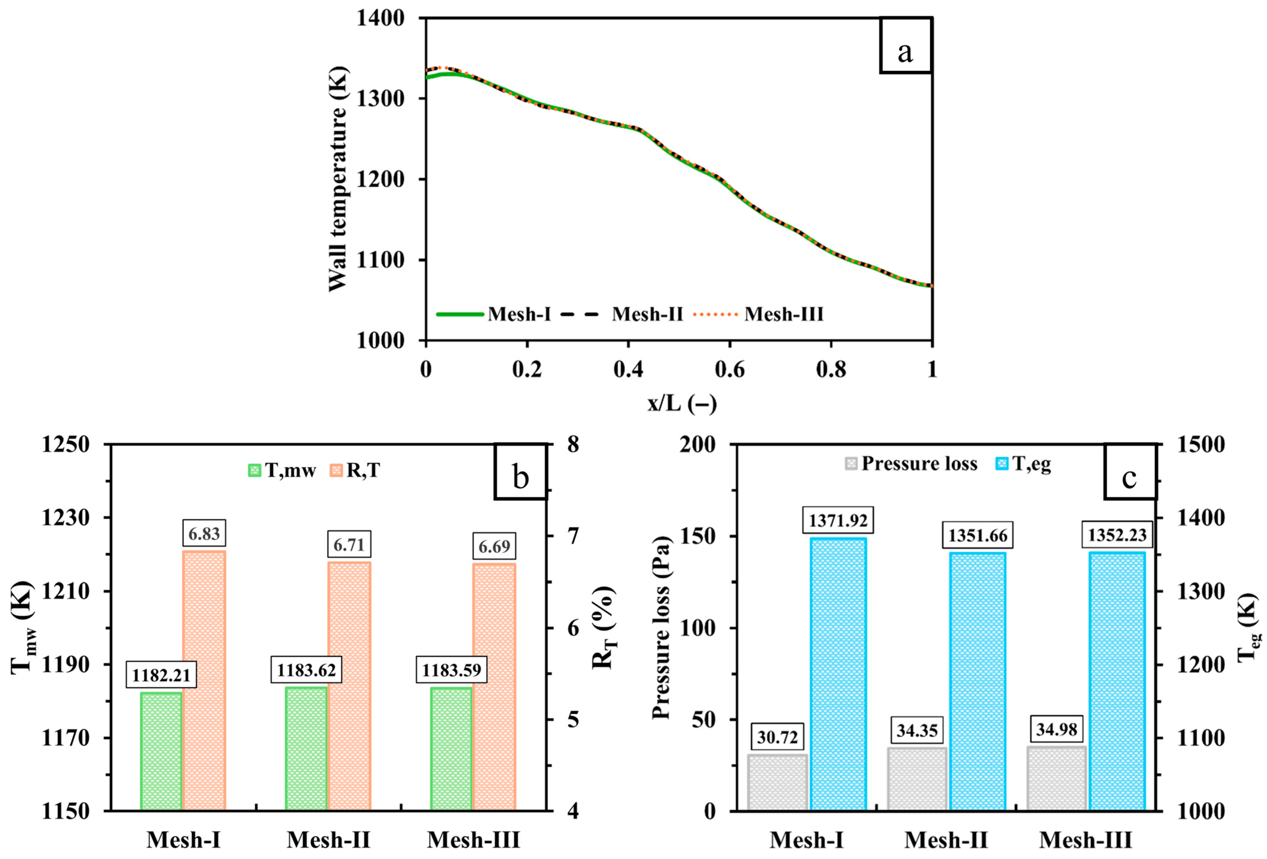
A grid independence test is conducted in this work to confirm accurate prediction of findings while maintaining a reasonable computational cost. As an example, the wall temperature, , , pressure loss, and of a gyroid design configuration integrated into a micro-combustor at an inlet volume flow rate and equivalence ratio of 600 mL/min and 1, respectively, is shown in Figure 2 for three different mesh resolutions with cell numbers of 461,619 (Mesh-I), 988,449 (Mesh-II), and 1,334,940 (Mesh-III). Figure 2a demonstrates that the wall temperature profiles for Mesh-II and Mesh-III are highly similar, whereas Mesh-I underpredicts the wall temperature in the inlet region. The results of and illustrated in Figure 2b support this observation as the discrepancies between Mesh-I and Mesh-III are 1.38 K and 0.14%, respectively, while those between Mesh-II and -III are only 0.03 K and 0.02%. In addition, Figure 2c shows that Mesh-I, compared to Mesh-III, shows a lower prediction of pressure loss by 4.26 Pa and a higher prediction of by 19.69 K. However, the pressure loss and values obtained with the medium mesh resolution (Mesh-II) are roughly the same as those of the high mesh resolution (Mesh-III). Therefore, Mesh-II provides a good balance between accuracy and computational efficiency and is selected for all simulations.
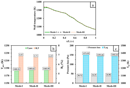
Figure 2.
A comparison of (a) the wall temperature, (b) and , and (c) pressure loss and of a micro-combustor employing a gyroid design configuration with three different mesh densities. x stands for the distance from the inlet, and L stands for the distance from the inlet and outlet.
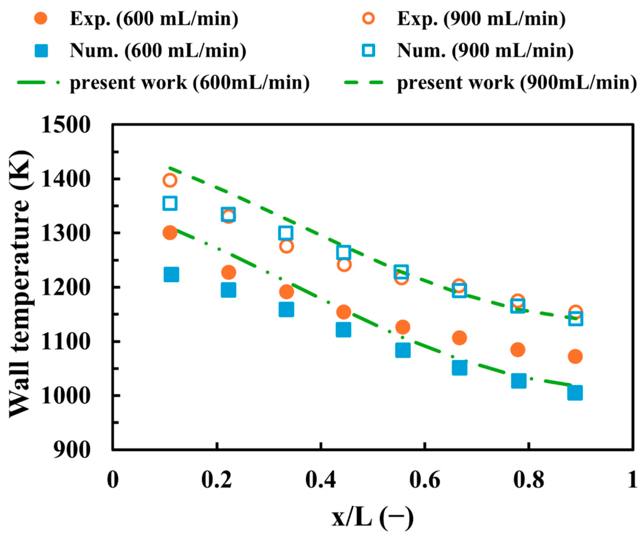
To confirm the reliability of the numerical setup, Figure 3 shows the validation of the modeling approaches used in this work against experimental [55] and numerical [56] findings at an inlet equivalence ratio of unity and velocities of 600 mL/min and 900 mL/min. Similar to the investigations outlined above, Figure 3 illustrates that the wall temperature in this work decreases with the flame’s progression from the inlet to the outlet at different velocities. For the 600 mL/min case, the maximum discrepancies between the results of this work and the experimental and numerical data are 5.1% and 7.03%, respectively, while for an inlet volume flow rate of 900 mL/min, the discrepancies are 3.92% and 4.82%, respectively. These discrepancies from the experimental work could be attributed to uncertainties in temperature measurement, limitations in data acquisition systems, or human errors during experimentation, whereas the numerical errors could result from mesh resolution or the use of different modeling or sub-modeling approaches. In general, the results of this work show high consistency and acceptable levels of deviation, indicating the reliability of the numerical method used in the current investigation.
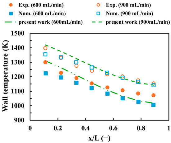
Figure 3.
A model validation.
3. Results and Discussion
3.1. Effects of TPMS Topologies and Inner Structure Lengths
This subsection discusses the effects of employing different TPMS designs, namely, gyroid, lidinoid, and Neovius, in micro-combustors, focusing on key thermal and performance metrics. Additionally, three lengths of these configurations (5 mm, 9 mm, and 13 mm) are investigated to assess design parameters for optimization. All simulations presented in this study are conducted with an inlet volume flow rate of 600 mL/min and an equivalence ratio of 1.
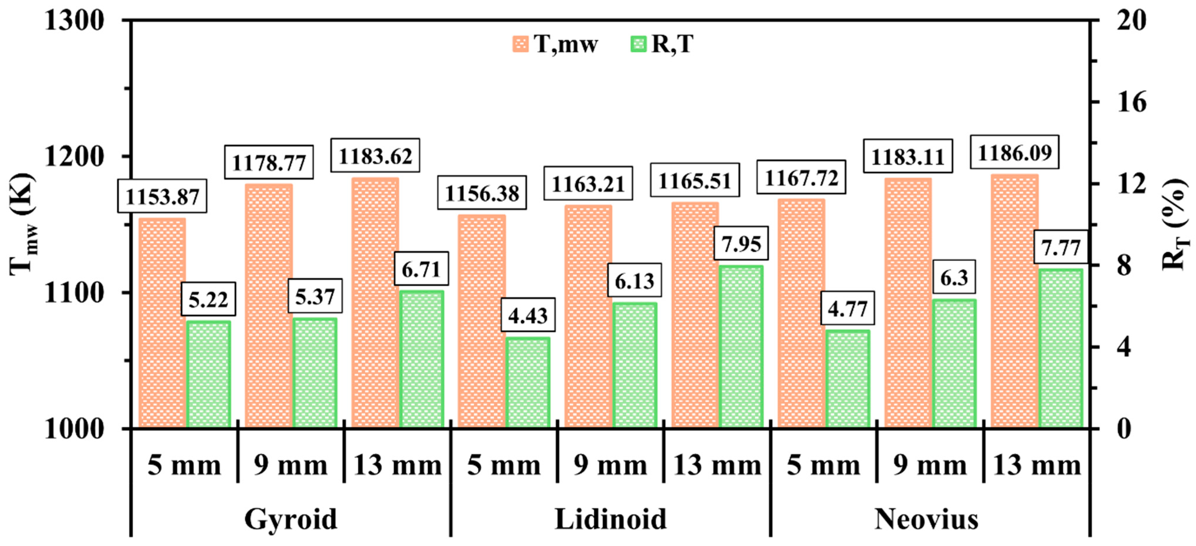
Figure 4 illustrates the impact of the gyroid, lidinoid, and Neovius configurations on and with different internal structure lengths. As seen in Figure 4, transitioning the length from 5 mm to 13 mm exhibits an effective means of gradually enhancing for all structures. This improvement is attributed to the increased surface area, which enhances the heat transfer process from the combustion to the outer walls. Moreover, shorter structures exhibit better wall temperature uniformity across all cases. This is because the 13 mm configurations tend to suppress the free propagation of the hydrogen flame farther downstream from the inlet region. In comparison with other designs, the gyroid structure shows the poorest performance in terms of both and at the 5 mm length. Nonetheless, the proportionally higher porosity of gyroid at the 13 mm length results in a superior performance. Meanwhile, the Neovius design consistently delivers the highest thermal energy to the walls, confirming its potential to enhance heat absorption in the micro-combustor walls.
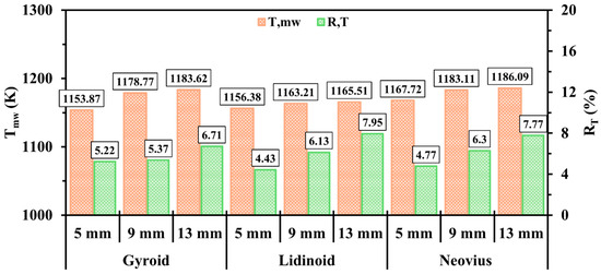
Figure 4.
The effects of gyroid, lidinoid, and Neovius along with their inner structure lengths on and .
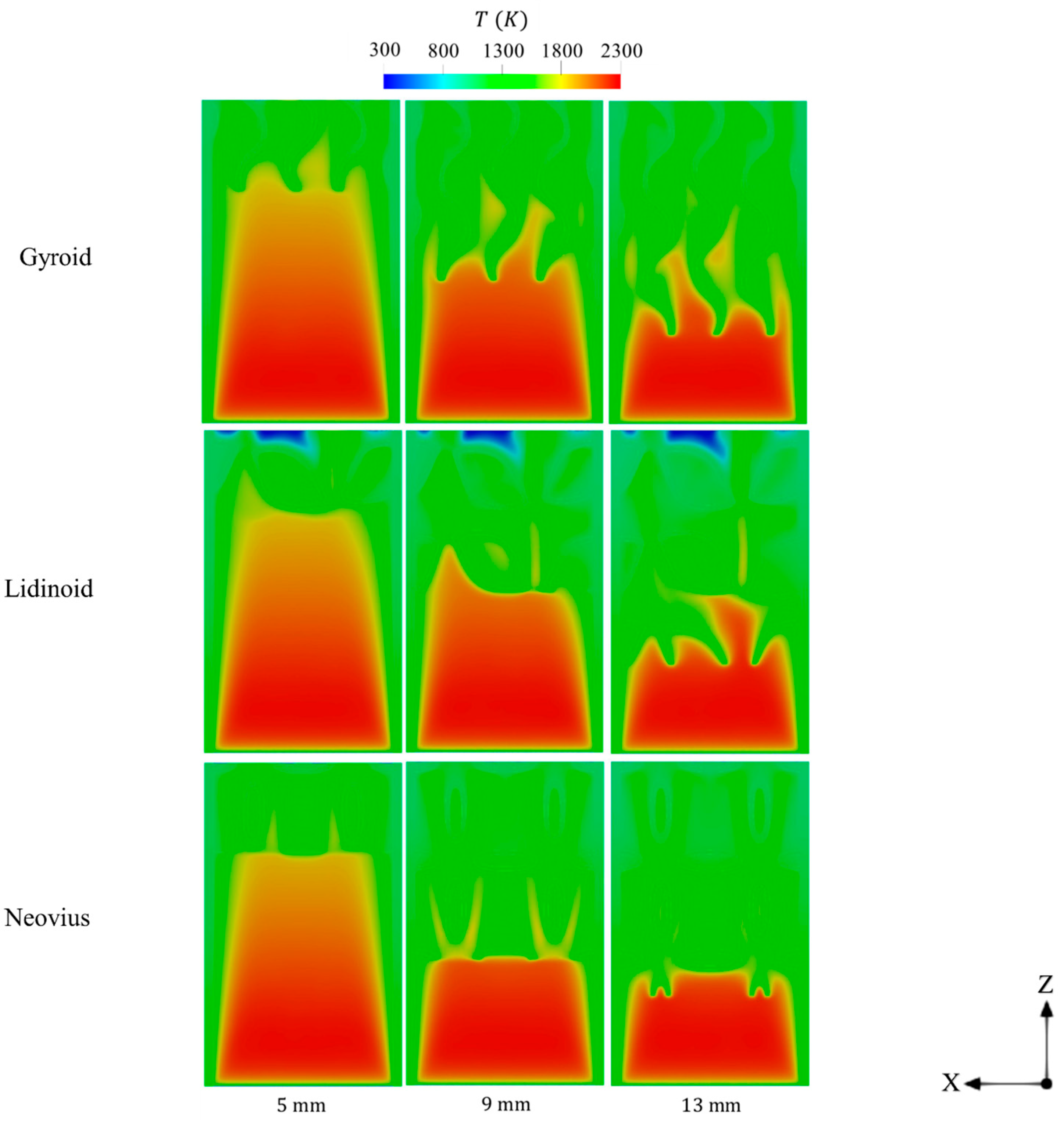
Figure 5 displays the effects of embedding various lengths of internal structures of gyroid, lidinoid, and Neovius on the spatial distribution of in-combustor temperature. As observed, the shorter-length configurations allow the high-temperature flame to propagate more freely throughout a larger volume, which contributes to better wall temperature uniformity as also shown in Figure 4. However, increasing the length of the internal structures helps to retain the flame with high thermal energy within the combustor, thereby extending the flow residence time and enabling the walls to absorb more heat. This observation aligns with the gradual increase in seen with longer structures in Figure 4. It is worth noting that some regions within the lidinoid structure exhibit low temperature variations near the outlet. This could be attributed to the high geometrical complexity of the lidinoid configuration, which may obstruct flame propagation into certain areas. Therefore, it is important to take into account spatial condensations when designing lidinoid geometries to avoid such performance drawbacks. In contrast, Figure 5 shows that the relative lower porosity of the Neovius structure confines the high-temperature flame to narrower regions in the medium- and long-length cases, resulting in less uniform wall temperatures compared to the other designs.
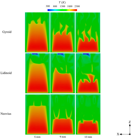
Figure 5.
Temperature contours of different lengths of gyroid, lidinoid, and Neovius structures.
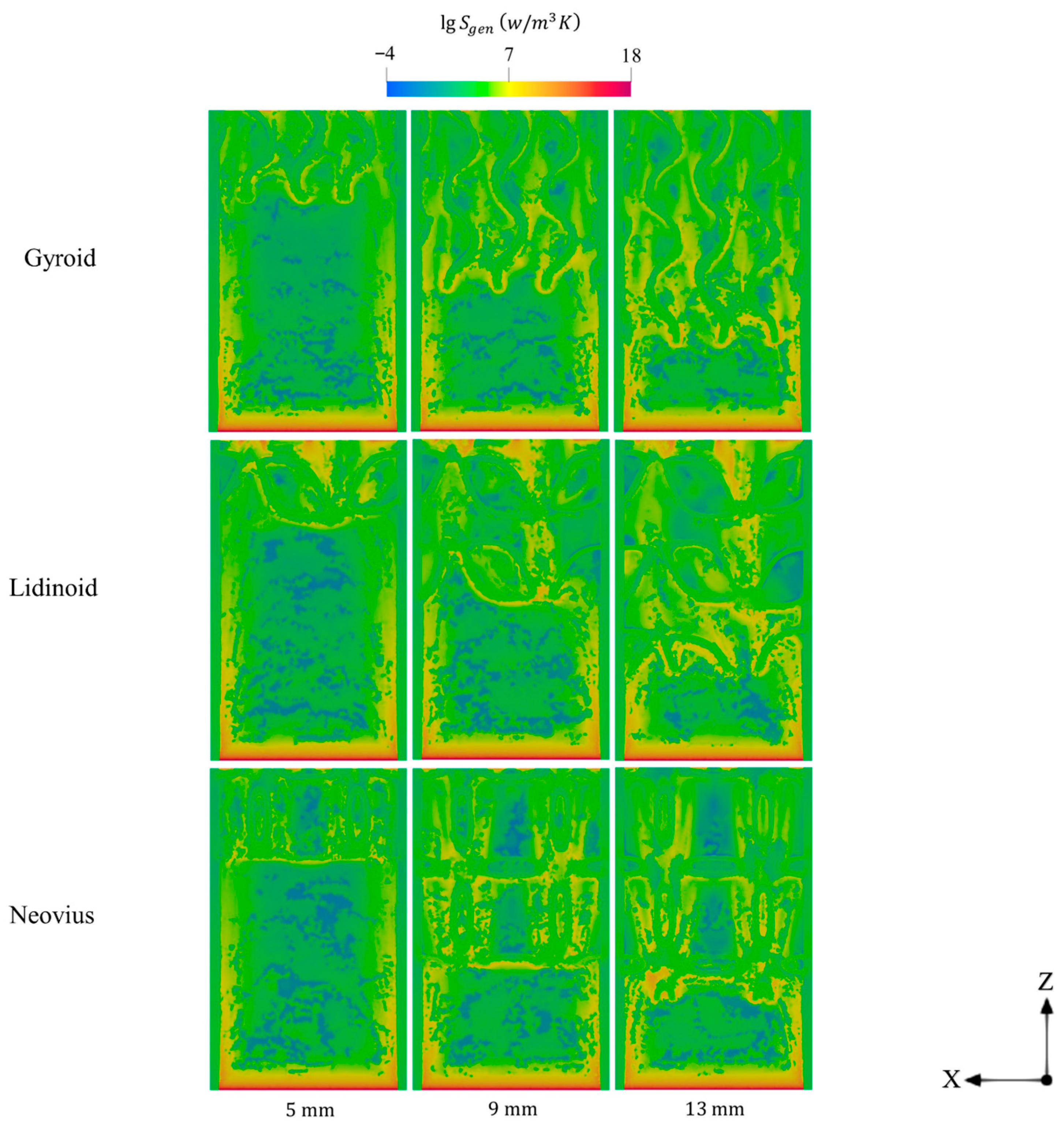
Figure 6 presents the contours of entropy generation over different lengths of the gyroid, lidinoid, and Neovius configurations. In the combustion onset region, high temperatures, intense chemical reactions, and elevated species production and consumption rates significantly enhance the mechanisms incorporated to account for entropy generations. As a result, all configurations exhibit high entropy production in this region regardless of internal geometry length. Extending the length of the internal structures increases the surface area, thereby enhancing the contact between hot gases and solid surfaces. This intensifies entropy generation via heat conduction, driven by the temperature gradient between the high-energy gas flow and the internal structures. Consequently, as shown in Figure 6, entropy generation becomes more widespread throughout the micro-combustor with increasing TPMS structure length.
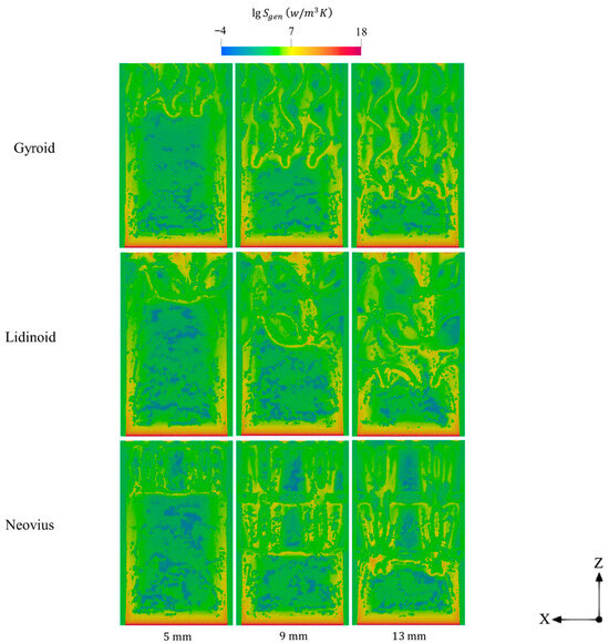
Figure 6.
Spatial variations of entropy generations for various lengths gyroid, lidinoid, and Neovius structures.
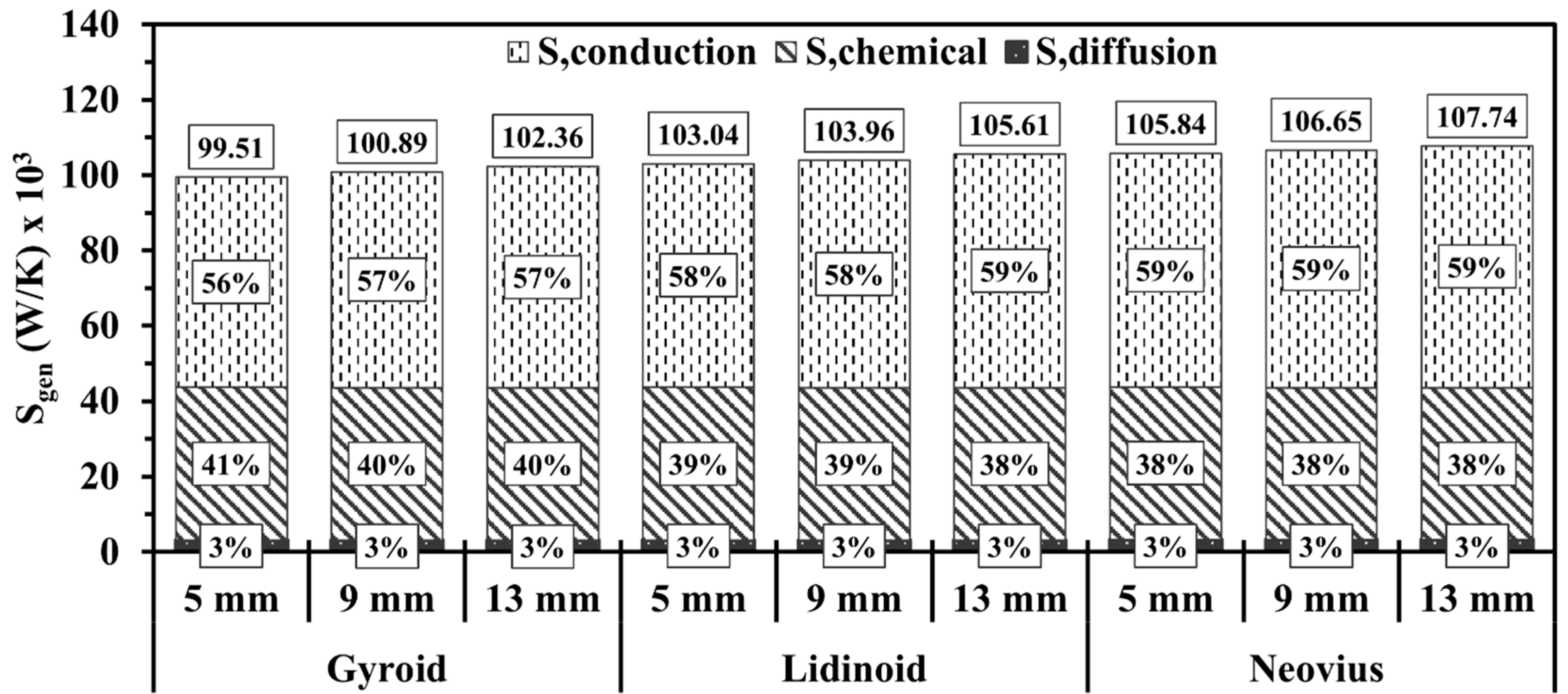
Figure 7 illustrates the variations in total entropy generation and the contribution percentages of conduction, chemical reaction, and diffusion mechanisms for the gyroid, lidinoid, and Neovius structures at different lengths. Increasing the length of the internal configurations results in a slight but consistent increase in total entropy generation in all cases. As can be seen in Figure 7, heat conduction is the dominant mechanism contributing to entropy generation, and its relative share increases as the structure length increases. In comparison with lidinoid and Neovius, the gyroid structure exhibits the lowest total entropy generation attributed to its higher porosity. In contrast, the Neovius structure, owing to its lower porosity, produces the highest entropy magnitude due to increased flow resistance and more intensive heat transfer interactions.
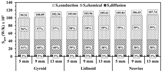
Figure 7.
Volume integrals of total entropy generations for gyroid, lidinoid, and Neovius structures with different lengths.
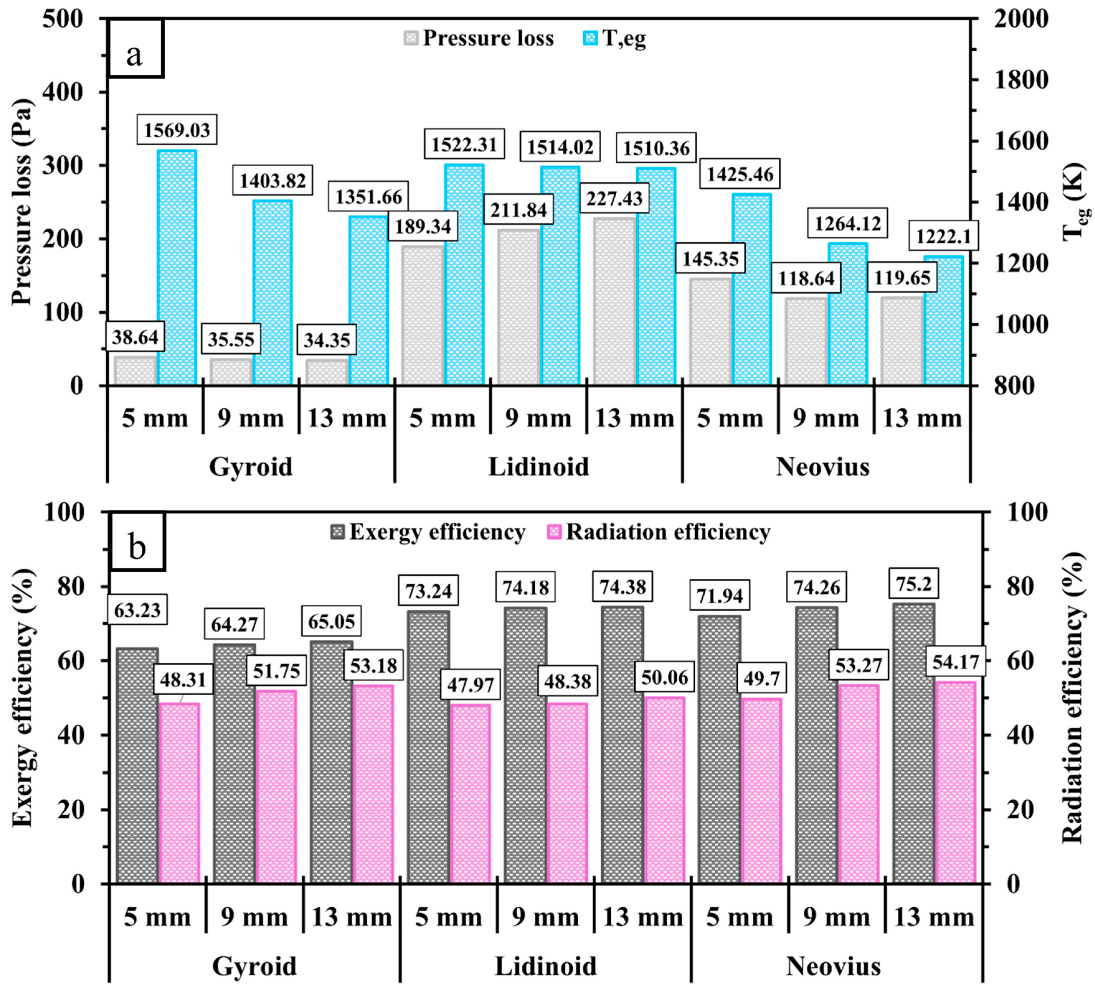
Figure 8 compares the pressure loss, , and the exergy and radiation efficiencies of gyroid, lidinoid, and Neovius configurations with different lengths. Figure 8a shows that increasing the length of the internal structure reduces pressure loss in the gyroid and Neovius configurations. However, the lidinoid structure exhibits an increasing trend in pressure loss with length due to its higher geometrical complexity. Among all designs, lidinoid consistently shows the highest pressure loss, while gyroid exhibits the lowest, attributed to its more open pore structure. As expected, increasing the length of the inner structures enhances surface area and thus improves heat transfer. This results in a gradual decrease in in all cases. Consequently, both exergy and radiation efficiencies increase with length, as can be seen in Figure 8b. Overall, the Neovius configuration demonstrates the best performance, achieving the highest radiation efficiency and the lowest , making it the optimal design in comparison with the other TPMS-based structures. This domination can be attributed to the flow field characteristics of the Neovius structure, which generate effective recirculation zones, leading to improved convective heat transfer between the high-thermal-energy flow and the walls.
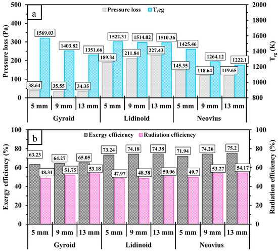
Figure 8.
Comparisons of (a) pressure loss, , (b) exergy and radiation efficiencies between gyroid, lidinoid, and Neovius configurations with different lengths.
3.2. Effects of Inlet Velocity
To evaluate the performance of TPMS-based structures housed in micro-combustor applications under different operating conditions, this section examines the effects of increasing the inlet velocity by means of varying the inlet volume flow rate from 600 mL/min to 900 mL/min on key thermal and performance parameters at an equivalence ratio of 1 using the 13 mm TPMS structures.
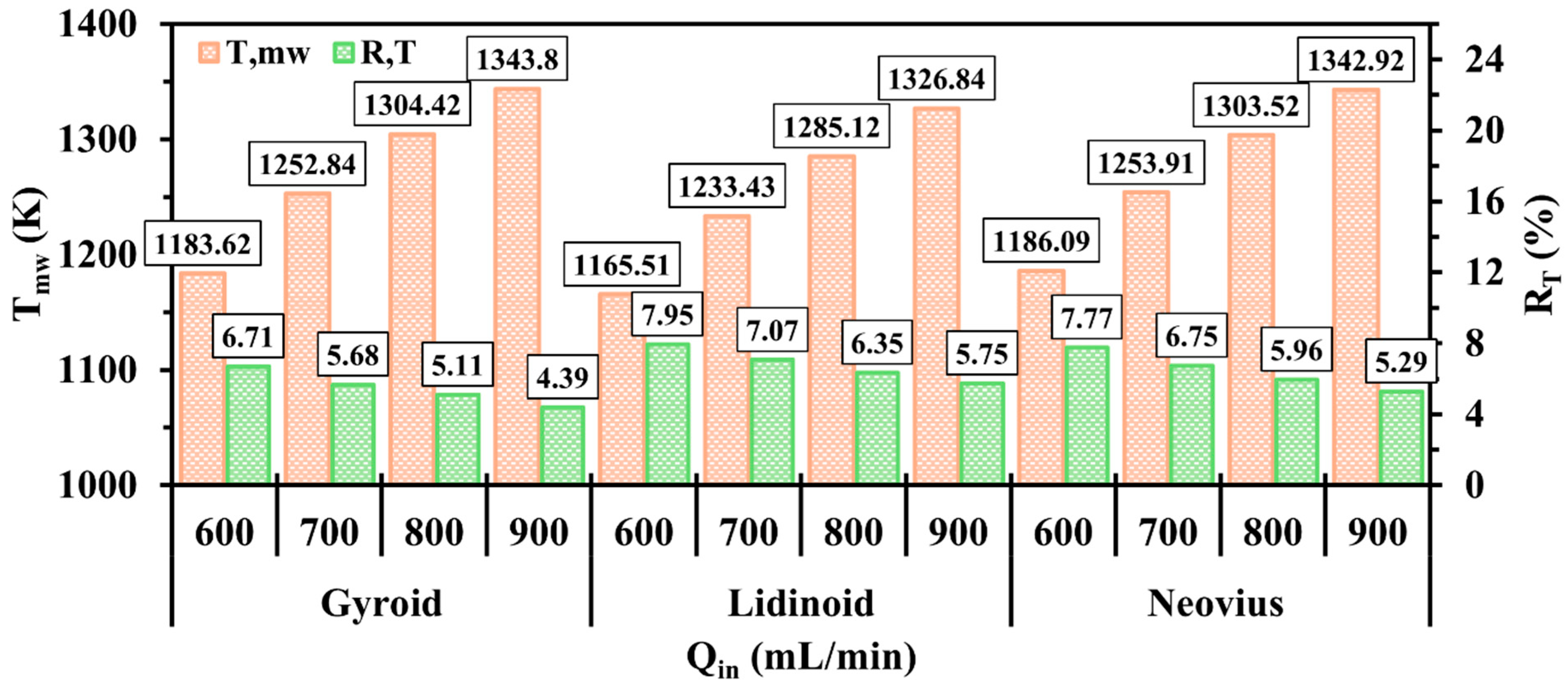
Figure 9 shows and of micro-combustors incorporating gyroid, lidinoid, and Neovius configurations under various conditions of . Overall, increasing effectively raises for all configurations as the system is supplied with a higher amount of input energy. In addition, the TPMS designs exhibit more uniform wall temperatures as approaches 900 mL/min primarily due to the extended propagation of the hydrogen flame. As shown in Figure 9, the lidinoid structure consistently demonstrates the lowest performance compared to gyroid and Neovius. In contrast, the gyroid configuration achieves both the highest mean wall temperature and uniformity wall temperature as its improvement rates at higher surpass those of Neovius. These results suggest that the gyroid structure is better suited to transferring thermal energy from combustion to the external walls, particularly when the system is operated at higher fuel input rates.
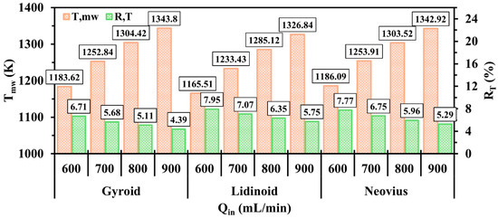
Figure 9.
The effects of different on , and in micro-combustors integrating gyroid, lidinoid, and Neovius structures.
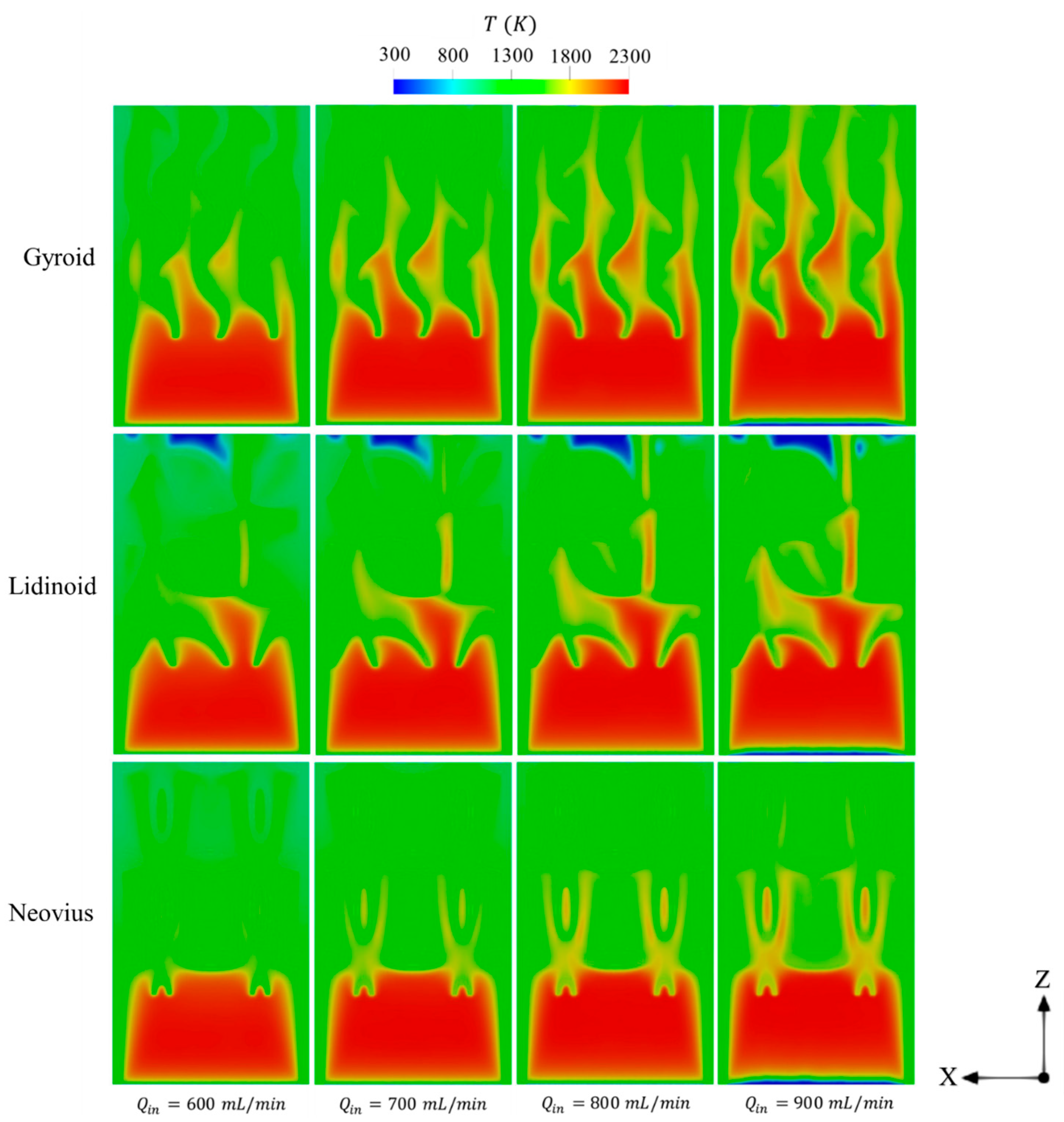
Figure 10 displays the spatial temperature distributions in different TPMS designs under varying . As increases, the high-temperature flame occupies a larger volumetric region within the combustor, driven by the enhanced combustion rate resulting from the increased energy input. In particular, the gyroid configuration allows the high-temperature flame to extend farther downstream, nearly reaching the outlet region, at higher . This broader flame propagation promotes more even heat distribution over the outer surfaces and enables a larger area of the external walls to absorb thermal energy, thereby increasing . These observations explain the superior performance of the gyroid structure as reflected by its highest and lowest temperature uniformity ratio compared to the other configurations as shown in Figure 9.
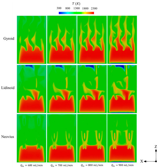
Figure 10.
The distributions of temperature in gyroid, lidinoid, and Neovius structures under different .
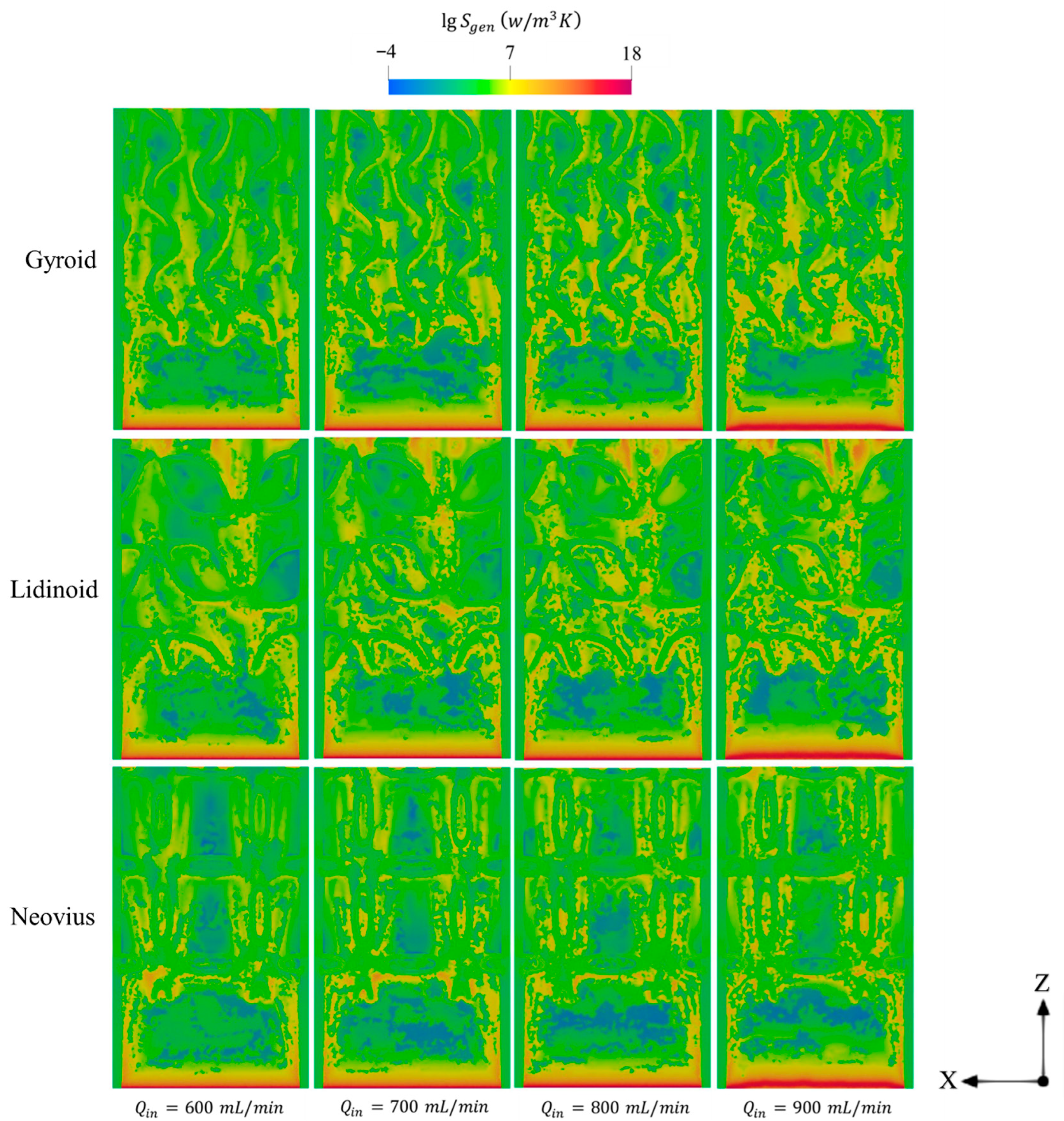
Figure 11 illustrates the effects of employing TPMS structures in micro-combustors on entropy generation. Supplying the system with higher amounts of fuel results in more intense combustion, which increases entropy generation through chemical reaction and diffusion mechanisms, which are caused by elevated reaction rates and species consumption, respectively. As shown in Figure 11, the regions of peak entropy generation near the inlet (where combustion is initiated) tend to expand with increasing across all geometries. Furthermore, higher lead to more chaotic entropy distribution throughout the combustor domain, indicating greater overall entropy generation under these conditions.
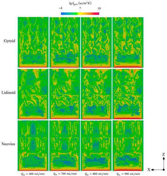
Figure 11.
Spatial variations of total entropy generations in gyroid, lidinoid, and Neovius structures at various .
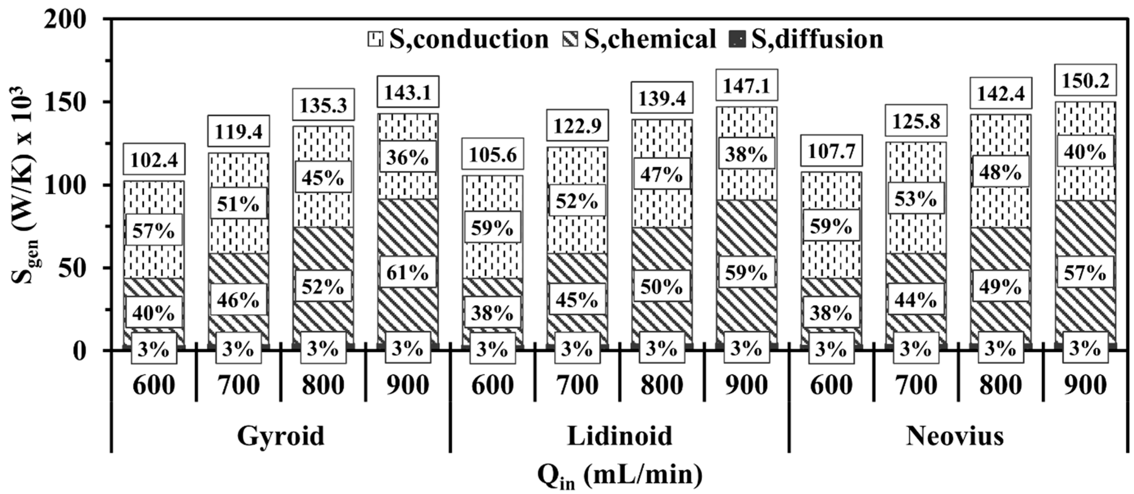
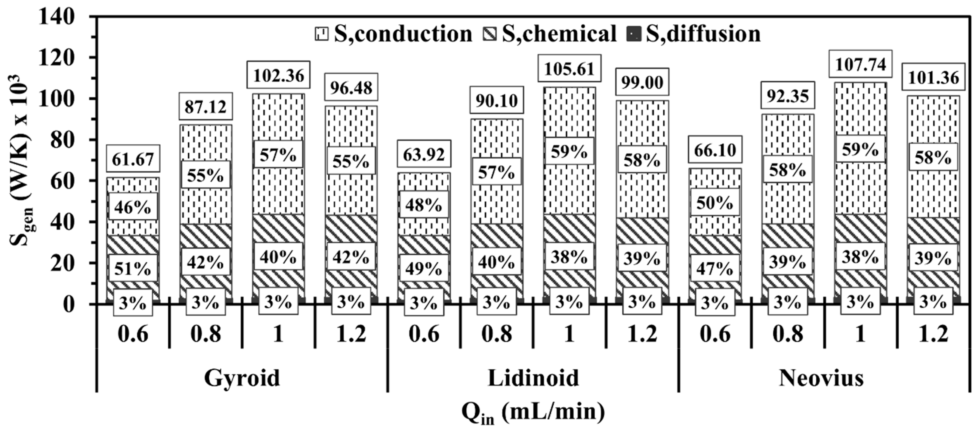
Figure 12 presents the volume-integrated total entropy generation and the contribution percentages of the three entropy generation mechanisms, namely conduction, chemical reaction, and diffusion, for the gyroid, lidinoid, and Neovius structures under different . For all test cases, increasing results in a rise in the total entropy generation rate. A key observation from Figure 12 is that the increased entropy generation at higher primarily results from the chemical reaction mechanism, which becomes the dominant contributor under such conditions. Since the entropy generated by chemical reactions is governed by the reaction rate, as described in Equation (13), this suggests that supplying more fuel enhances species consumption and production rates, thereby intensifying the combustion process. In comparison with other configurations, the Neovius structure consistently exhibits the highest total entropy generation under different conditions of , followed by the lidinoid and then the gyroid, which maintains the lowest entropy levels due to its proportional higher porosity and more favorable flow characteristics.
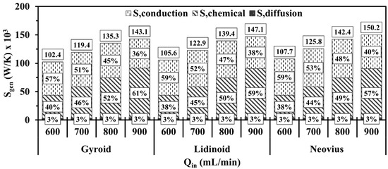
Figure 12.
Volume integral of total entropy generations of different TPMS structures at various .
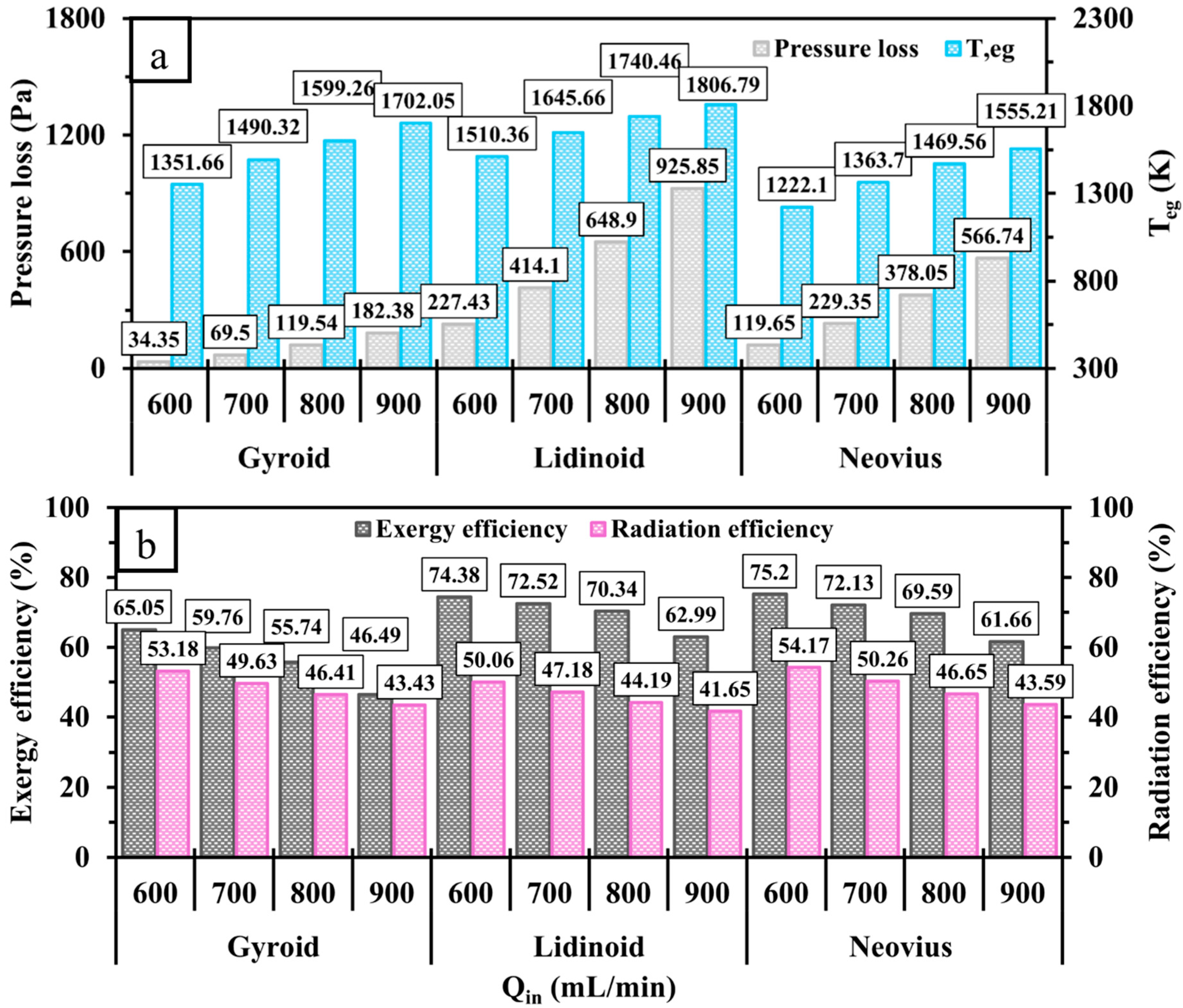
Figure 13 illustrates the effects of incorporating TPMS structures on pressure loss, , exergy efficiency, and radiation efficiency. As shown in Figure 13a, pressure loss increases significantly at higher due to the increased collision frequency between the incoming flow and the internal walls. In contrast to the other configurations, the lidinoid structure, owing to its complex geometry, experiences the highest pressure loss, while the gyroid design consistently shows the lowest due to its relatively high porosity. Injecting a higher flow rate of hydrogen into the system leads to a notable rise in , indicating that the micro-combustor’s small scale may limit its ability to accommodate high-power inputs effectively. As a result, both exergy and radiation efficiencies decline with increasing , as depicted in Figure 13b. Under the tested conditions, the Neovius structure demonstrates the highest overall efficiency. However, its radiation efficiency declines more sharply with increased compared to the gyroid design. This suggests that, while Neovius performs best at lower , the gyroid configuration may be more suitable for higher-velocity operating conditions.
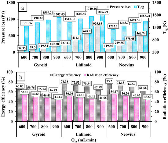
Figure 13.
A comparison of (a) pressure loss, , (b) exergy and radiation efficiencies for gyroid, lidinoid, and Neovius designs at various .
3.3. Effects of Inlet Equivalence Ratio
To optimize the operating conditions, this subsection compares the performance of the proposed TPMS configurations with respect to various equivalence ratios between 0.6 and 1.2 to investigate the effects of fuel-lean and fuel-rich conditions on micro-combustor performance. Based on the findings of the previous subsection, an inlet volume flow rate of 600 mL/min is identified as the optimal condition. Therefore, this inlet volume flow rate is used for all subsequent simulations in this subsection.
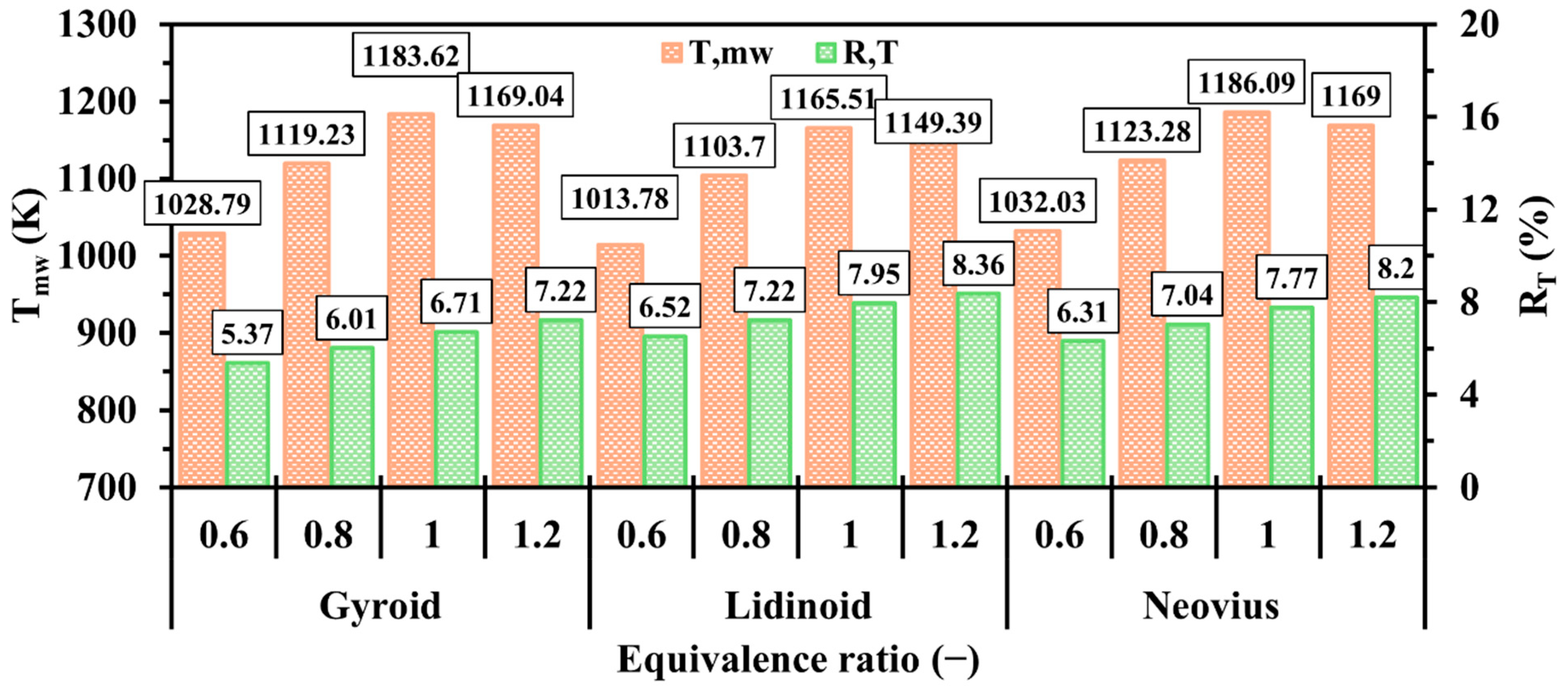
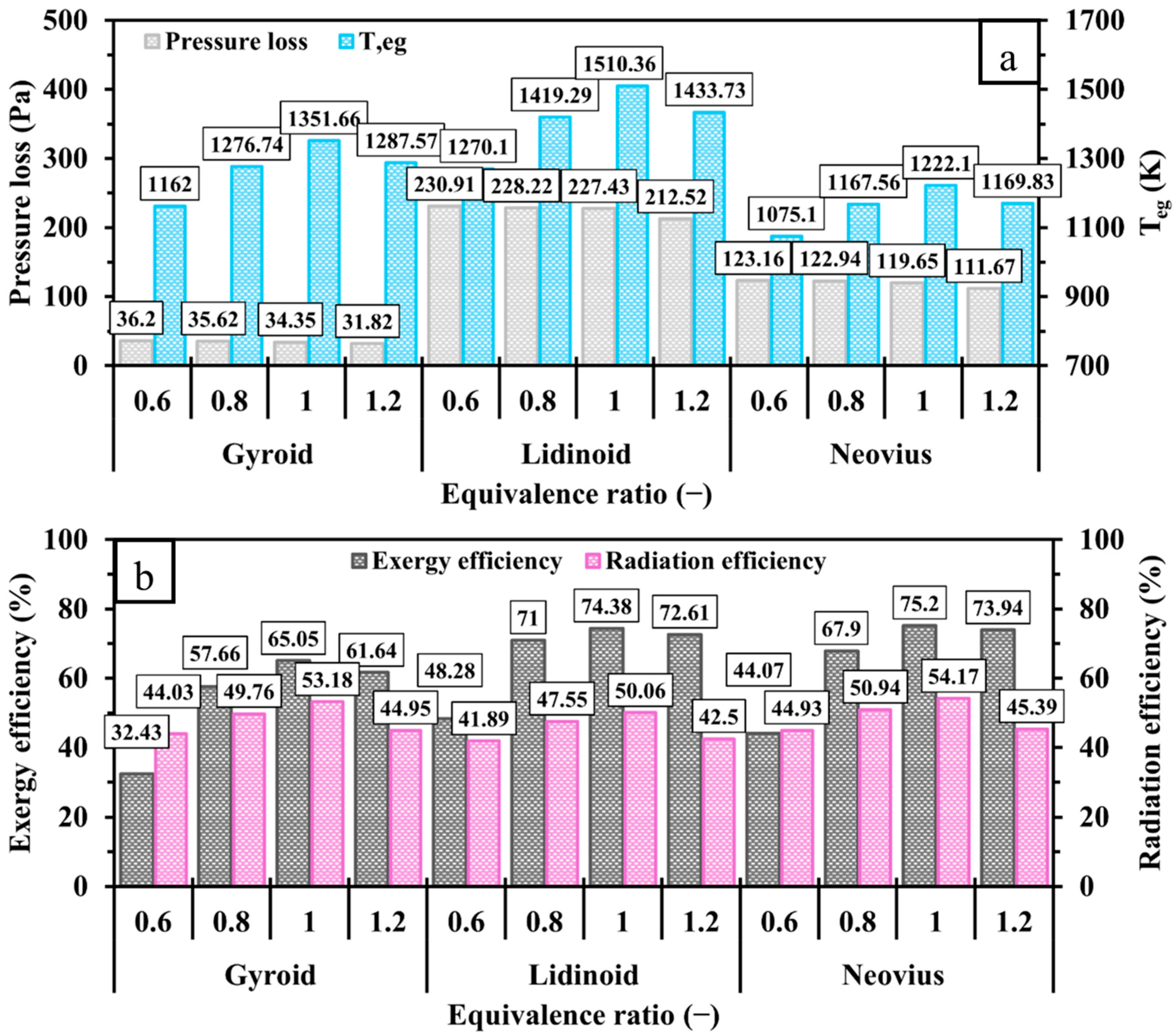
Figure 14 shows the effects of varying on the tested TPMS structures with respect to and . Increasing from 0.6 to 1 leads to a significant rise in for all configurations as more fuel is supplied to the system, reaching optimal combustion at the stoichiometric condition . However, as increases further toward the fuel-rich condition , begins to decline, indicating insufficient oxygen for complete hydrogen combustion. Despite the initial improvement in , all configurations exhibit reduced wall temperature uniformity as increases from 0.6 to 1.2. Among the TPMS designs, the lidinoid structure consistently shows the lowest and under all equivalence ratios. In contrast, the Neovius configuration achieves higher and than gyroid under lean to stoichiometric conditions. However, under rich conditions , the gyroid structure demonstrates superior performance, reaching the highest (1169 K) while maintaining better temperature uniformity (gyroid: 7.22%; Neovius: 8.2%). This suggests that the gyroid design is more ideal for fuel-rich operating regimes.
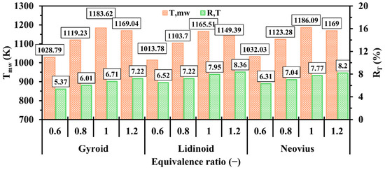
Figure 14.
A comparison of and at various between gyroid, lidinoid, and Neovius designs.
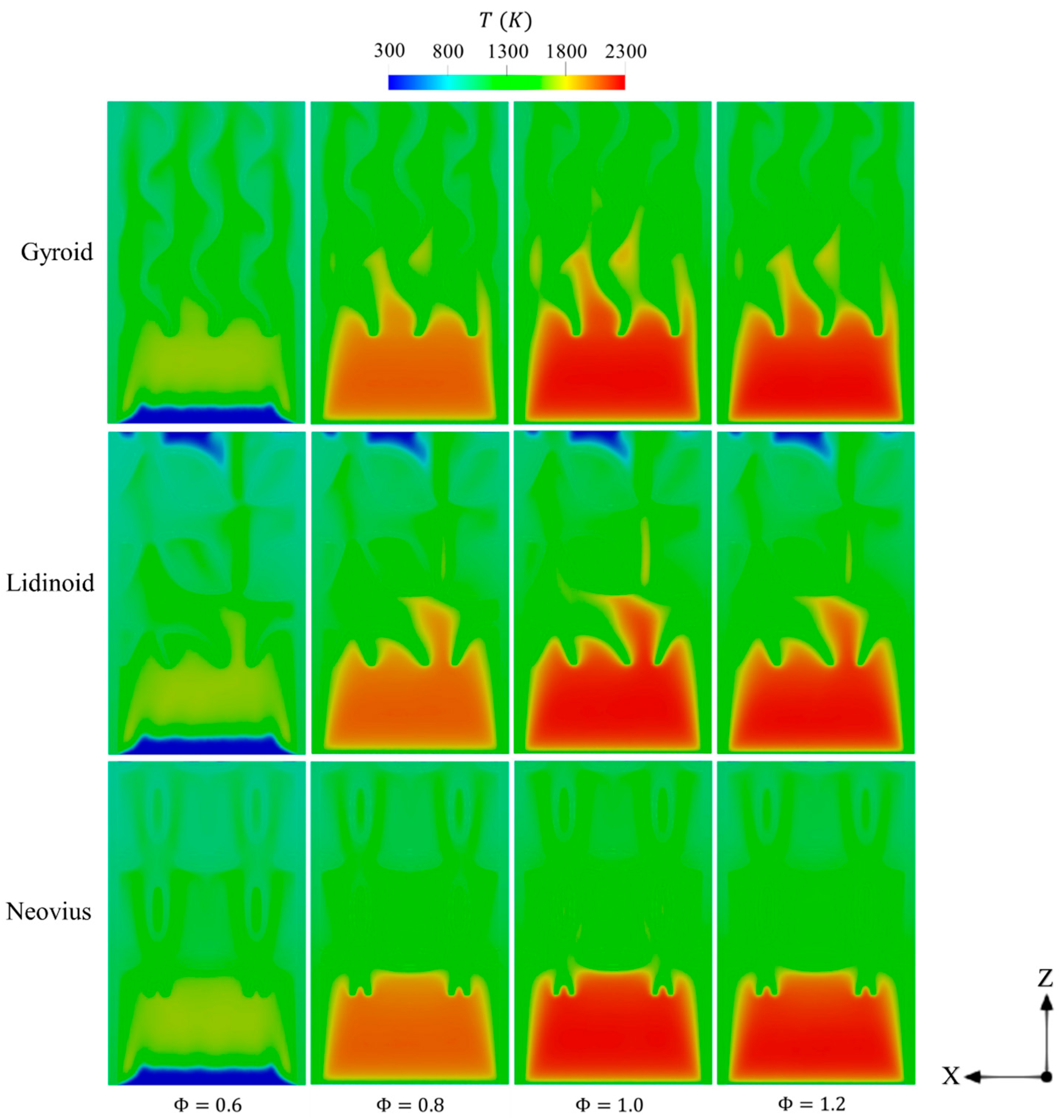
The effects of variations on the temperature distribution within the TPMS configurations are illustrated in Figure 15. Compared to the stoichiometric case , lean conditions result in the onset of combustion occurring farther downstream from the inlet and exhibit reduced combustion intensity due to the limited hydrogen supply. Conversely, under rich conditions , the lower availability of oxygen reduces the hydrogen consumption rate, also leading to a less vigorous combustion process. These observations highlight that the stoichiometric condition offers the most balanced fuel–oxidizer ratio, which enhances chemical reactivity and leads to more effective and intense combustion throughout the combustor.
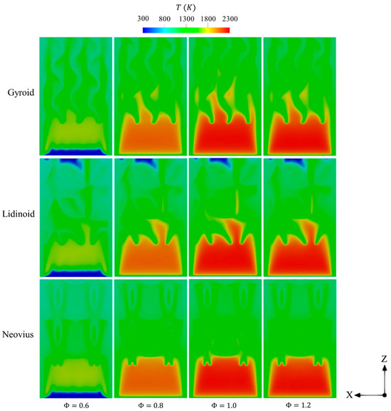
Figure 15.
Spatial variations of temperature of gyroid, lidinoid, and Neovius designs under different conditions of .
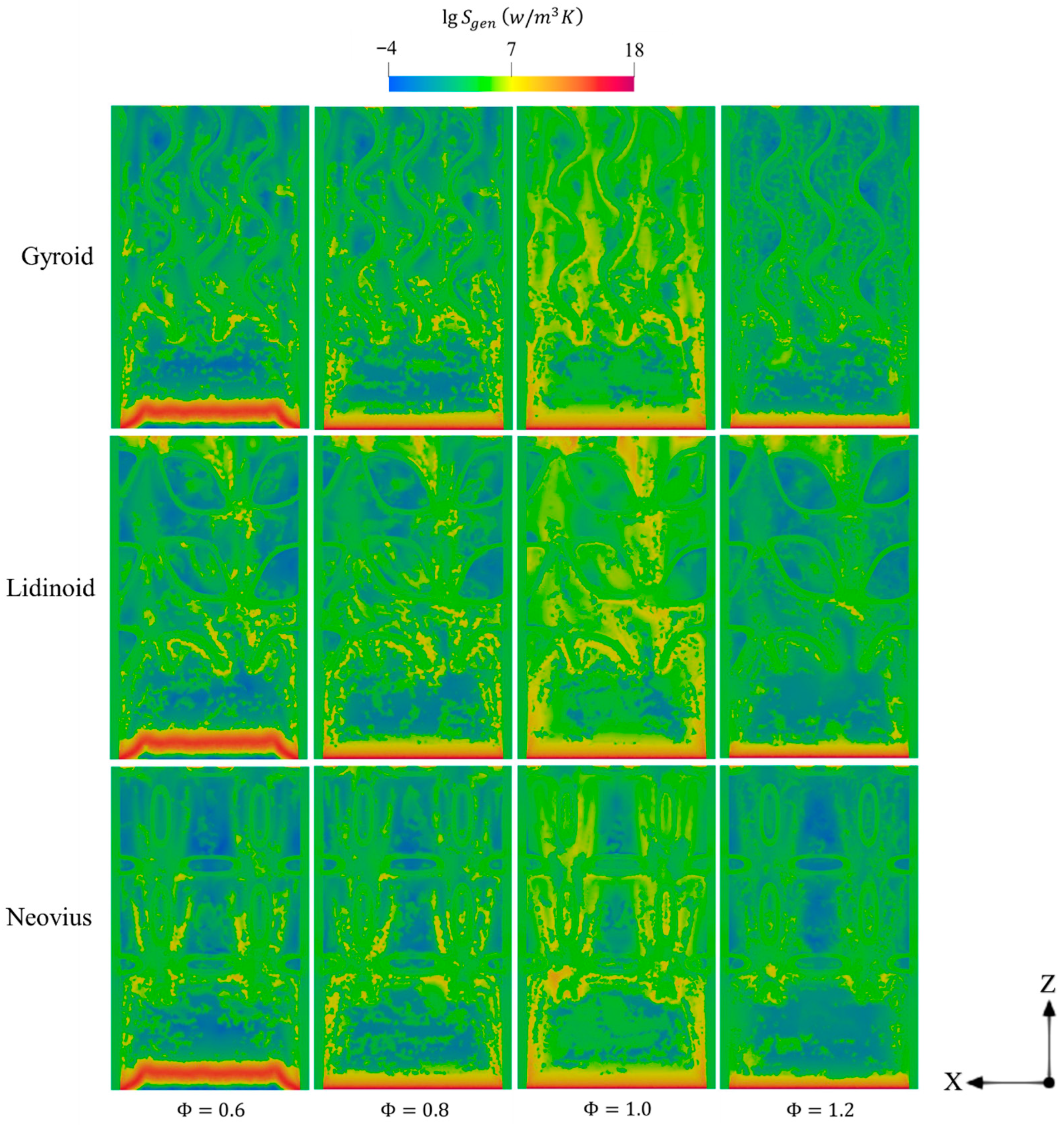
Figure 16 illustrates the impact of variations on entropy generation in the gyroid, lidinoid, and Neovius designs. As shown, increasing from 0.6 to 1 significantly broadens the spatial extent of entropy generation within the micro-combustor. This indicates that enriching the premixed charge with more fuel enhances the combustion rate, thereby intensifying the mechanisms considered to account for entropy. However, under rich conditions , the reduced oxygen availability limits hydrogen consumption, leading to lower thermal output and, consequently, a decrease in overall entropy generation compared to the stoichiometric case.
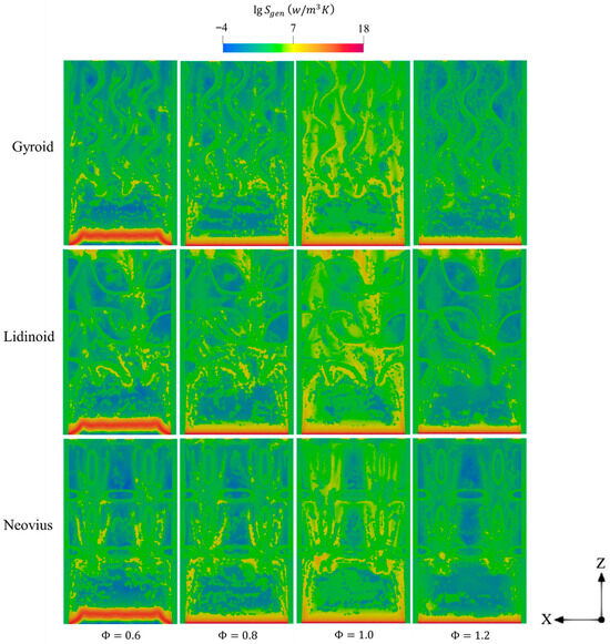
Figure 16.
The distribution of total entropy generation throughout the domain of gyroid, lidinoid, and Neovius designs with respect to different .
Figure 17 shows the variations in total entropy production for the gyroid, lidinoid, and Neovius structures across a range of . For all configurations, increasing from lean to stoichiometric conditions results in a rise in entropy generation, followed by a decline as moves toward fuel-rich conditions. This trend closely aligns with the behavior of the heat conduction contribution, suggesting that temperature gradients are the dominant factor in overall entropy generation. The observed peak at of 1 can be attributed to the optimal fuel–air ratio, which maximizes the heat release rate and, consequently, the thermal gradients within the combustor. Under different cases, the gyroid structure consistently exhibits the lowest total entropy generation, whereas the Neovius structure shows the highest. This reinforces previous findings regarding the influence of geometry characteristics and relative higher porosity on entropy-related performance.
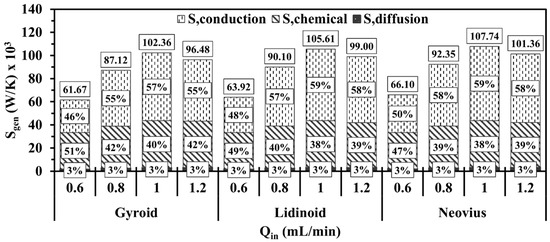
Figure 17.
Volume integral of total entropy generations in terms of different Φ for gyroid, lidinoid, and Neovius designs.
Figure 18 compares the effects of the gyroid, lidinoid, and Neovius structures on pressure loss, , exergy efficiency, and radiation efficiency at different values. As shown in Figure 18a, shifting Φ toward fuel-rich conditions results in a slight decrease in pressure loss across all TPMS-based structures, suggesting that less pumping power is required for mixtures with higher fuel content. However, increases significantly under stoichiometric conditions, indicating greater thermal energy losses. Figure 18b shows that both exergy and radiation efficiencies improve as increases from 0.6 to 1 but then decline when reaches 1.2. Although rich conditions supply more energy to the combustor, the 0.8– case achieves higher exergy and radiation efficiencies than the 1.2 case. This is due to the increased entropy generation and elevated exhaust temperatures associated with rich combustion. Overall, the evaluated performance parameters suggest that varying tends not to substantially alter the relative performance ranking among the TPMS structures due to the alignments of trends observed in the previous subsections.
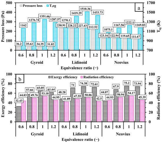
Figure 18.
Variations in (a) pressure loss, ; (b) exergy and radiation efficiencies at a range of for different TPMS configurations.
4. Conclusions
This work investigates the integration of triply periodic minimal surface (TPMS) configurations, namely gyroid, lidinoid, and Neovius, into a hydrogen-fueled micro-combustor and evaluates their effects on flow dynamics, flame stabilization, and thermal performance. Comprehensive computational fluid dynamics simulations are conducted, employing a finite-rate model with a stiff chemistry solver to predict the chemical reactions and a laminar flow model to describe the flow field. The study examines the impacts of varying TPMS length, inlet volume flow rate , and equivalence ratio (), aiming at optimizing both design and operating conditions. The main findings are summarized as follows:
- Increasing the length of all examined geometries significantly enhances , indicating improved heat transfer due to the increased surface area within the combustor domain. Consequently, all structures demonstrate decreasing trends in and increasing trends in total entropy generation, as well as improved exergy and radiation efficiencies when transitioning from short (5 mm) to long (13 mm) internal geometries. However, approaching the longest length suppresses hydrogen flame propagation, leading to reduced wall temperature uniformity. Compared to other configurations, Neovius achieves the highest performance metrics but exhibits slightly less uniform wall temperature than the gyroid.
- Elevating leads to improvements in both and as more energy is supplied to the system. However, higher also results in significantly greater entropy generation due to more vigorous combustion. These conditions also cause increased pressure loss and along with reduced exergy and radiation efficiencies, suggesting that the small scale of the micro-combustor limits its ability to fully utilize higher power inputs. Notably, the gyroid structure exhibits the smallest reduction in efficiency at higher velocities, implying better suitability for high-power operating conditions.
- As increases from lean to stoichiometric and then to rich conditions, all structures show a corresponding rise and then fall in , pressure loss, entropy generation, and both exergy and radiation efficiencies, with optimal performance occurring at the stoichiometric point. This confirms that provides the best balance between fuel and oxidizer for maximizing combustion efficiency, despite resulting in the highest . The heat conduction component of entropy generation, driven by temperature gradients, also follows this trend, peaking at Φ = 1. Across all values, the Neovius structure generally outperforms the gyroid and lidinoid configurations in terms of thermal and performance metrics.
Overall, the outcome indicates that employing the TPMS configurations can potentially serve as efficient and compact heat sources for thermophotovoltaic systems. Integrating such structures into the micro-combustor can accelerate the development of portable power supplies and micro-scale renewable energy devices where efficiency, stability, and low emissions are critical. For this, it is important to focus on experimental validation in future work on integrating these combustors into practical thermophotovoltaic technologies.
Funding
This work was supported by the Deanship of Scientific Research, King Faisal University, Saudi Arabia [Grant No.: KFU253278].
Data Availability Statement
The data presented in the study are included in the article, and further inquiries can be directed to the corresponding author.
Acknowledgments
The author gratefully acknowledges the Deanship of Scientific Research at King Faisal University (Saudi Arabia) for supporting this research as part of the Research Grants Program [Raed Grant No.: KFU253278]. The author also would like to gratefully acknowledgment King Abdullah University of Science and Technology (KAUST) for their support in permitting the use of the high computing facilities to conduct the numerical investigations.
Conflicts of Interest
The author declares that he has no known competing financial interests or personal relationships that could have appeared to influence the work reported in this paper.
Abbreviations
| MEMS | Micro-electro-mechanical system |
| MTPV | Micro-thermophotovoltaic |
| TPMS | Triply periodic minimal surface |
| Unit tensor, | |
| Inlet volume flow rate, | |
| Vector velocity, | |
| Peclet number, | |
| Total energy of the fluid, | |
| Effective thermal conductivity, | |
| Reaction net rate of production of species i | |
| Specific enthalpy of species j, | |
| Surface area of the outer wall, | |
| Outer wall area of cell i, 2 | |
| Diffusion flux of species , | |
| Total entropy generation, | |
| Entropy generation as a result of chemical reaction, | |
| Entropy generation as a result of heat conduction, | |
| Entropy generation as a result of mass diffusion, | |
| Mixture thermal conductivity, | |
| Reference enthalpy of species i, | |
| Reference entropy of species i, | |
| Inlet exergy, | |
| Total exergy losses, | |
| Uncounted exergy destruction, | |
| Energy loss from the combustion exhaust gas, | |
| Natural convection heat transfer coefficient, | |
| Exhaust gas temperature, | |
| Temperature of external wall, | |
| Area-weighted-mean wall temperature, | |
| Outer wall temperature of cell i, | |
| Ambient temperature, | |
| Mass diffusivity of species i, | |
| Mass flow rate of inlet flow, | |
| Mass flow rate of fuel, | |
| Velocity, | |
| Specific heat capacity, | |
| Gas constant, | |
| Lower heating value, | |
| Pressure, | |
| Pressure loss, | |
| Inlet pressure, | |
| Outlet pressure, | |
| Atmospheric pressure, | |
| Hydraulic diameter, | |
| Local mass fraction of species i, | |
| Wall temperature uniformity, | |
| Heat losses due to radiation, | |
| Heat losses due to convection, | |
| Source term of enthalpy, | |
| Greek letters | |
| Mixture gas density, | |
| Mole fraction of species i, | |
| Viscous stress, | |
| Reynolds stress, | |
| Molecular viscosity, | |
| Chemical potential of species i, | |
| Mass fraction of species i, | |
| Stephan–Boltzmann constant, | |
| Equivalence ratio, | |
| Thermal conductivity, | |
| Solid surface emissivity, | |
| Exergy efficiency, | |
| Radiation efficiency, | |
| Production rate of species i, |
References
- Fontana, É.; Battiston, L.; Oliveira, R.G.A.; Capeletto, C.A.; Luz, L.F.L. Beyond the Combustion Chamber: Heat Transfer and Its Impact on Micro-Thermophotovoltaic Systems Performance. Energy 2022, 239, 122184. [Google Scholar] [CrossRef]
- Hosseini, S.E.; Wahid, M. Investigation of Bluff-Body Micro-Flameless Combustion. Energy Convers. Manag. 2014, 88, 120–128. [Google Scholar] [CrossRef]
- Banerjee, A.; Paul, D. Developments and Applications of Porous Medium Combustion: A Recent Review. Energy 2021, 221, 119868. [Google Scholar] [CrossRef]
- Ju, Y.; Maruta, K. Microscale Combustion: Technology Development and Fundamental Research. Prog. Energy Combust. Sci. 2011, 37, 669–715. [Google Scholar] [CrossRef]
- Wan, J.; Fan, A. Recent Progress in Flame Stabilization Technologies for Combustion-Based Micro Energy and Power Systems. Fuel 2021, 286, 119391. [Google Scholar] [CrossRef]
- Kang, X.; Veeraragavan, A. Experimental Demonstration of a Novel Approach to Increase Power Conversion Potential of a Hydrocarbon Fuelled, Portable, Thermophotovoltaic System. Energy Convers. Manag. 2017, 133, 127–137. [Google Scholar] [CrossRef]
- Walther, D.C.; Ahn, J. Advances and Challenges in the Development of Power-Generation Systems at Small Scales. Prog. Energy Combust. Sci. 2011, 37, 583–610. [Google Scholar] [CrossRef]
- Zhang, Y.; Xiao, S.; Lu, Q.; Chen, W.; Quaye, E.K.; Pan, J. Numerical Study on Non-Premixed Combustion Characteristics of NH3/O2 in Multi-Inlet Micro Combustor. Appl. Therm. Eng. 2023, 224, 120091. [Google Scholar] [CrossRef]
- Zhang, Y.; Lu, Q.; Fan, B.; Quaye, E.K.; Weng, J.; Xiao, S.; Pan, J. Effect of Intake Method on Ammonia/Oxygen Non-Premixed Combustion in the Micro Combustor with Dual-Inlet. Fuel 2022, 317, 123504. [Google Scholar] [CrossRef]
- Sun, Y.; Zhao, D.; Cai, T. Dilution Effect on Thermal Performances and NOx Emission Characteristics of an Ammonia-Oxygen Micro-Thermophotovoltaic System. Therm. Sci. Eng. Prog. 2022, 34, 101401. [Google Scholar] [CrossRef]
- Yao, Z.; Liu, J.; Zhang, P.; Li, S.; Sun, Y.; He, M. Effect of Sinusoidal Wall Geometry on Flame Stability and Thermal Performance in Hydrogen-Air Premixed Micro-Combustors. Appl. Therm. Eng. 2025, 279, 127719. [Google Scholar] [CrossRef]
- Sun, Y.; Li, L.; Huang, X. Thermal Performance and NOx Emission Study of an Ammonia-Oxygen Enriched Opposed-Flow Inlet Micro-Combustor for Zero-Carbon Thermophotovoltaic Applications. Appl. Therm. Eng. 2025, 278, 127395. [Google Scholar] [CrossRef]
- Raghavan, K.A.S.; Rao, S.S.; Raju, V.R.K. Numerical Investigation of the Effect of Slit-Width on the Combustion Characteristics of a Micro-Combustor with a Centrally Slotted Bluff Body. Int. J. Hydrogen Energy 2023, 48, 5696–5707. [Google Scholar] [CrossRef]
- Wan, J.; Fan, A.; Maruta, K.; Yao, H.; Liu, W. Experimental and Numerical Investigation on Combustion Characteristics of Premixed Hydrogen/Air Flame in a Micro-Combustor with a Bluff Body. Int. J. Hydrogen Energy 2012, 37, 19190–19197. [Google Scholar] [CrossRef]
- Zuo, W.; Li, D.; E, J.; Xia, Y.; Li, Q.; Quan, Y.; Zhang, G. Parametric Study of Cavity on the Performance of a Hydrogen-Fueled Micro Planar Combustor for Thermophotovoltaic Applications. Energy 2023, 263, 126028. [Google Scholar] [CrossRef]
- Rong, H.; Zhao, D. Thermodynamic and Entropy Generation Analyses of Telsa-Valve Structured Meso-Scale Combustors Fuelled with Hydrogen for Thermophotovoltaic Applications. Energy 2024, 307, 132788. [Google Scholar] [CrossRef]
- Zhang, Y.; Lu, Q.; Fan, B.; Chen, W.; Jiang, C.; Pan, J.; Jia, R. Study on the Non-Premixed Combustion Characteristics and Exergy Analysis of H2/Air in Vase-Shaped Micro Combustor. Appl. Therm. Eng. 2023, 233, 121104. [Google Scholar] [CrossRef]
- Al-Ketan, O.; Rowshan, R.; Abu Al-Rub, R.K. Topology-Mechanical Property Relationship of 3D Printed Strut, Skeletal, and Sheet Based Periodic Metallic Cellular Materials. Addit. Manuf. 2018, 19, 167–183. [Google Scholar] [CrossRef]
- Parittothok, P.; Poolwech, C.; Tanteng, T.; Wongwiwat, J. Performance Improvement of Glass Microfiber Based Thermal Transpiration Pump Using TPMS. Micromachines 2022, 13, 1632. [Google Scholar] [CrossRef]
- Dixit, T.; Al-Hajri, E.; Paul, M.C.; Nithiarasu, P.; Kumar, S. High Performance, Microarchitected, Compact Heat Exchanger Enabled by 3D Printing. Appl. Therm. Eng. 2022, 210, 118339. [Google Scholar] [CrossRef]
- Kus, K.; Wójcik, M.; Malecha, Z.; Rogala, Z. Numerical and Experimental Investigation of the Gyroid Heat Exchanger. Int. J. Heat Mass Transf. 2024, 231, 125882. [Google Scholar] [CrossRef]
- Barakat, A.; Sun, B. Controlling TPMS Lattice Deformation for Enhanced Convective Heat Transfer: A Comparative Study of Diamond and Gyroid Structures. Int. Commun. Heat Mass Transf. 2024, 154, 107443. [Google Scholar] [CrossRef]
- Dube Kerme, E.; Hajialibabei, M.; Ziad Saghir, M.; El-Ketan, O. Experimental Investigation of Porous Gyroid Structure: Effect of Cell Size and Porosity on Performance. Therm. Sci. Eng. Prog. 2024, 53, 102728. [Google Scholar] [CrossRef]
- Gado, M.G.; Ookawara, S.; Hassan, H. Utilization of Triply Periodic Minimal Surfaces for Performance Enhancement of Adsorption Cooling Systems: Computational Fluid Dynamics Analysis. Energy Convers. Manag. 2023, 277, 116657. [Google Scholar] [CrossRef]
- Padrão, D.; Hancock, D.; Paterson, J.; Schoofs, F.; Tuck, C.; Maskery, I. New Structure-Performance Relationships for Surface-Based Lattice Heat Sinks. Appl. Therm. Eng. 2024, 236, 121572. [Google Scholar] [CrossRef]
- Piatti, C. Assessment of Thermal-Hydraulic Performance of Circular Pipes Equipped with Triply Periodic Minimal Surfaces. Bachelor’s Thesis, Politecnico di Torino, Turino, Italy, 2023. [Google Scholar]
- Wang, J.; Chen, K.; Zeng, M.; Ma, T.; Wang, Q.; Cheng, Z. Investigation on Flow and Heat Transfer in Various Channels Based on Triply Periodic Minimal Surfaces (TPMS). Energy Convers. Manag. 2023, 283, 116955. [Google Scholar] [CrossRef]
- Xu, H.; Yu, W.; Zhang, Y.; Ma, S.; Wu, Z.; Liu, X. Flow and Heat Transfer Performance of Bionic Heat Transfer Structures with Hybrid Triply Periodic Minimal Surfaces. Appl. Energy 2023, 351, 121847. [Google Scholar] [CrossRef]
- Iwaniszyn, M.; Sindera, K.; Maszybrocka, J.; Jodłowski, P.J. 3D-Printed Triply Periodic Minimal Surface (TPMS) Structures as Catalyst Carriers. Chem. Eng. Res. Des. 2024, 209, 37–51. [Google Scholar] [CrossRef]
- Beer, M.; Rybár, R. Optimisation of Heat Exchanger Performance Using Modified Gyroid-Based TPMS Structures. Processes 2024, 12, 2943. [Google Scholar] [CrossRef]
- Su, X.; Zhang, Y.; Rao, Y.; Yeranee, K.; Wang, X. Experimental and Numerical Study on Flow and Heat Transfer Characteristics of Additively Manufactured Triply Periodic Minimal Surface (TPMS) Heat Exchangers for Micro Gas Turbine. Aerospace 2025, 12, 416. [Google Scholar] [CrossRef]
- Kilic, G.A. Performance Evaluation of Triply Periodic Minimal Surface Heat Exchangers Using Nanofluids at High Flow Rates for Enhanced Energy Efficiency. Appl. Sci. 2025, 15, 4140. [Google Scholar] [CrossRef]
- Tang, W.; Zhou, H.; Zeng, Y.; Yan, M.; Jiang, C.; Yang, P.; Li, Q.; Li, Z.; Fu, J.; Huang, Y.; et al. Analysis on the Convective Heat Transfer Process and Performance Evaluation of Triply Periodic Minimal Surface (TPMS) Based on Diamond, Gyroid and Iwp. Int. J. Heat Mass Transf. 2023, 201, 123642. [Google Scholar] [CrossRef]
- Renon, C.; Jeanningros, X. A Numerical Investigation of Heat Transfer and Pressure Drop Correlations in Gyroid and Diamond TPMS-Based Heat Exchanger Channels. Int. J. Heat Mass Transf. 2025, 239, 126599. [Google Scholar] [CrossRef]
- du Plessis, A.; Razavi, N.; Benedetti, M.; Murchio, S.; Leary, M.; Watson, M.; Bhate, D.; Berto, F. Properties and Applications of Additively Manufactured Metallic Cellular Materials: A Review. Prog. Mater. Sci. 2022, 125, 100918. [Google Scholar] [CrossRef]
- Feng, J.; Fu, J.; Yao, X.; He, Y. Triply Periodic Minimal Surface (TPMS) Porous Structures: From Multi-Scale Design, Precise Additive Manufacturing to Multidisciplinary Applications. Int. J. Extrem. Manuf. 2022, 4, 022001. [Google Scholar] [CrossRef]
- ANSYS Fluent User’s Guide, Release 23.2; ANSYS, Inc.: Canonsburg, PA, USA, 2023.
- Yang, X.; Yu, B.; Peng, X.; Zhou, H. Investigation of Thermal Performance and Energy Conversion in a Novel Planar Micro-Combustor with Four-Corner Entrances for Thermo-Photovoltaic Power Generators. J. Power Sources 2021, 515, 230625. [Google Scholar] [CrossRef]
- Sun, Y.; Cai, T.; Zhao, D. Thermal Performance and NOx Emission Characteristics Studies on a Premixed Methane-Ammonia-Fueled Micro-Planar Combustor. Fuel 2021, 291, 120190. [Google Scholar] [CrossRef]
- Ni, S.; Zhao, D.; Sellier, M.; Li, J.; Chen, X.; Li, X.; Cao, F.; Li, W. Thermal Performances and Emitter Efficiency Improvement Studies on Premixed Micro-Combustors with Different Geometric Shapes for Thermophotovoltaics Applications. Energy 2021, 226, 120298. [Google Scholar] [CrossRef]
- Ni, S.; Zhao, D.; Zhu, X. Heat Transfer and Entropy Production Evaluation on Premixed Hydrogen/Air-Fuelled Micro-Combustors with Internal Threads. Fuel 2021, 303, 121325. [Google Scholar] [CrossRef]
- Dai, C.; Zuo, W.; Li, Q.; Zhou, K.; Huang, Y.; Zhang, G.; E, J. Energy Conversion Efficiency Improvement Studies on the Hydrogen-Fueled Micro Planar Combustor with Multi-Baffles for Thermophotovoltaic Applications. Energy 2024, 313, 134099. [Google Scholar] [CrossRef]
- Yang, W.M.; Chua, K.J.; Pan, J.F.; Jiang, D.Y.; An, H. Development of Micro-Thermophotovoltaic Power Generator with Heat Recuperation. Energy Convers. Manag. 2014, 78, 81–87. [Google Scholar] [CrossRef]
- Cai, T.; Zhao, D. Effects of Fuel Composition and Wall Thermal Conductivity on Thermal and NOx Emission Performances of an Ammonia/Hydrogen-Oxygen Micro-Power System. Fuel Process. Technol. 2020, 209, 106527. [Google Scholar] [CrossRef]
- Li, J.; Huang, J.; Chen, X.; Zhao, D.; Shi, B.; Wei, Z.; Wang, N. Effects of Heat Recirculation on Combustion Characteristics of N-Heptane in Micro Combustors. Appl. Therm. Eng. 2016, 109, 697–708. [Google Scholar] [CrossRef]
- Li, J.; Chou, S.K.; Li, Z.W.; Yang, W.M. Characterization of Wall Temperature and Radiation Power through Cylindrical Dump Micro-Combustors. Combust. Flame 2009, 156, 1587–1593. [Google Scholar] [CrossRef]
- Peng, Q.; E, J.; Chen, J.; Zuo, W.; Zhao, X.; Zhang, Z. Investigation on the Effects of Wall Thickness and Porous Media on the Thermal Performance of a Non-Premixed Hydrogen Fueled Cylindrical Micro Combustor. Energy Convers. Manag. 2018, 155, 276–286. [Google Scholar] [CrossRef]
- He, Z.; Yan, Y.; Zhao, T.; Feng, S.; Li, X.; Zhang, L.; Zhang, Z. Heat Transfer Enhancement and Exergy Efficiency Improvement of a Micro Combustor with Internal Spiral Fins for Thermophotovoltaic Systems. Appl. Therm. Eng. 2021, 189, 116723. [Google Scholar] [CrossRef]
- Sun, Y.; Zhao, D.; Ni, S.; David, T.; Zhang, Y. Entropy and Flame Transfer Function Analysis of a Hydrogen-Fueled Diffusion Flame in a Longitudinal Combustor. Energy 2020, 194, 116870. [Google Scholar] [CrossRef]
- Sahoo, B.B.; Saha, U.K.; Sahoo, N. Diagnosing the Effects of Pilot Fuel Quality on Exergy Terms in a Biogas Run Dual Fuel Diesel Engine. Int. J. Exergy 2012, 10, 77–93. [Google Scholar] [CrossRef]
- Stepanov, V.S. Chemical Energies and Exergies of Fuels. Energy 1995, 20, 235–242. [Google Scholar] [CrossRef]
- Tong, J.; Cai, T. Enhancing Thermal Performance, Exergy and Thermodynamics Efficiency of Premixed Methane/Air Micro-Planar Combustor in Micro-Thermophotovoltaic Systems. Energies 2023, 16, 118. [Google Scholar] [CrossRef]
- Xue, Z.; Yan, Y.; He, Z.; Shen, K.; Zhang, C. Comprehensive Numerical Insight the Thermal Performance Improvement of the Micro Combustors with Internal Bionic Y-Shaped Fins for Micro-Thermal Voltaic System Applications. Fuel 2022, 318, 123610. [Google Scholar] [CrossRef]
- Peng, Q.; Yang, W.; E, J.; Li, Z.; Xu, H.; Fu, G.; Li, S. Investigation on H2/Air Combustion with C3H8 Addition in the Combustor with Part/Full Porous Medium. Energy Convers. Manag. 2021, 228, 113652. [Google Scholar] [CrossRef]
- Tang, A.; Pan, J.; Yang, W.; Xu, Y.; Hou, Z. Numerical Study of Premixed Hydrogen/Air Combustion in a Micro Planar Combustor with Parallel Separating Plates. Int. J. Hydrogen Energy 2015, 40, 2396–2403. [Google Scholar] [CrossRef]
- Rong, H.; Zhao, D.; Cai, T.; Becker, S. Enhancing Thermal and Exergy Performances in a CO2-Free Micro-Combustor with Reverse Flow Double-Channel Outlet Structure. Appl. Therm. Eng. 2023, 233, 121180. [Google Scholar] [CrossRef]
Disclaimer/Publisher’s Note: The statements, opinions and data contained in all publications are solely those of the individual author(s) and contributor(s) and not of MDPI and/or the editor(s). MDPI and/or the editor(s) disclaim responsibility for any injury to people or property resulting from any ideas, methods, instructions or products referred to in the content. |
© 2025 by the author. Licensee MDPI, Basel, Switzerland. This article is an open access article distributed under the terms and conditions of the Creative Commons Attribution (CC BY) license (https://creativecommons.org/licenses/by/4.0/).

