Article

Effect of Neighboring Hole Impacts on Inter-Hole Dynamic Presplitting Process with Consideration of Crack Width Variations

1
State Key Laboratory of Water Resources Engineering and Management, Wuhan University, Wuhan 430072, China
2
Key Laboratory of Rock Mechanics in Hydraulic Structural Engineering, Ministry of Education, Wuhan University, Wuhan 430072, China
*
Author to whom correspondence should be addressed.
Appl. Sci. 2025, 15(18), 10036; https://doi.org/10.3390/app151810036
Submission received: 15 August 2025 / Revised: 7 September 2025 / Accepted: 11 September 2025 / Published: 14 September 2025
(This article belongs to the Special Issue Advanced Blasting Technology for Mining)

Abstract

To analyze the effect of neighboring hole impacts on the inter-hole presplitting process, the dynamic cracking behavior under explosive load and ground stress is theoretically investigated by developing an inter-hole cracking model. Considering the variations in crack width, the influence mechanisms of stress waves from both in-hole and adjacent holes on the dynamic cracking process of presplitting blasting are examined through numerical simulations. Meanwhile, explosion tests under different detonation conditions were carried out to verify and further elucidate the dynamic effects of inter-hole presplitting blasting. The results indicate that the opening of presplitting holes can be restricted, reduced, or even closed during the cracking formation process due to the stress wave from adjacent holes when detonated simultaneously. Furthermore, there is a tendency for inter-hole cracks to be constrained in the large-angle direction, limiting crack propagation. And millisecond detonation timing can reduce the dynamic stress superposition effect between pre-cracked holes, thereby mitigating the damage to the surrounding rock. This finding is particularly applicable to presplitting blasting technology.

1. Introduction

With the large-scale construction of large underground power plants in China, there is an increasing need for refined control over plant safety and quality, particularly concerning the vibration and damage of surrounding rock [1,2,3]. In the process of blasting excavation, the propagation and evolution of blast stress waves play an important role in the rock fracture and fragmentation [4,5,6]. These directly influence the vibration response strength and damage area. As shown in Figure 1, the primary objective of blast fracturing is to use inter-hole blast action to promote the crack expansion in zones I, II, and III, which means a greater crushing effect.
Currently, the most widely used mechanism for inter-hole blasting crack formation is based on traditional blasting theory, which focuses on the combined effects of blast stress waves and explosive gas pressure [7,8,9,10]. For example, Hino [11] proposed a shock wave tensile failure theory based on dynamic fracture tests of rocks, suggesting that stress waves induce reflected tensile failure at free surfaces. Sazid and Singh [12] investigated the dynamic blast energy evolution for elastoplastic rock cracking through numerical simulation, emphasizing the important role of stress wave loading for blast cracking. Langefors [13,14] proposed the theory of explosive gas expansion failure, suggesting that the high-temperature, high-pressure gas products generated by detonation expand and perform work within the rock after detonation, leading to rock failure. Kutter and Fairhurst [15] described the quasi-static pressure effects of explosive gases, noting that explosive gases can form a “quasi-static pressure field” within rock or exhibit an “explosive gas wedge effect [16]”. Dally et al. [17] concluded from experimental results that the work carried out by expanding blast gases in coupled charges can increase stress wave-induced fractures by 2 to 6 times. Larocque and Favreau [18] analyzed fracture distributions near boreholes through field and laboratory tests, explicitly proposing three stages of blasting fragmentation: a. radial fissures caused by stress waves; b. flaking induced by reflected waves; and c. expansion and ejection stages driven by blast gases. Daehnke et al. [19,20], based on PMMA explosion-induced fracturing experiments, concluded that blasting fractures result primarily from stress wave action (8%) and detonation gas action (92%).
Regarding the inter-hole crushing mechanism, Duvall and Petkof [21] proposed that the superposition of borehole stress waves promotes crack initiation at the midpoint between boreholes, which then propagates toward the boreholes. Yi et al. [22] discovered that the superposition of stress waves produced by adjacent blastholes contributed to the promotion of inter-hole rock fragmentation, while an increase in detonation delay decreased the quality of inter-hole fragmentation, that is, focusing on zones II and III in Figure 1. Ding et al. [23] investigated the evolution of the stress component of the double-hole blast wave with simultaneous detonation and found that the improper stress wave superposition will lessen the likelihood of crack initiation between holes. The influence of detonation delay on blasting, crushing, and vibration control was studied by blasting experiments and numerical simulations [24,25], and they both indicated the complexity of blasting processes and effects under low-delay conditions.
In contrast to inter-hole crushing, inter-hole pre-cracking blasting primarily aims to enhance the penetration of cracks along the inter-hole line (zone I) while mitigating crack propagation and minimizing damage in the retained rock mass (zones II and III), especially under complex high in situ stress conditions. He et al. [26] discovered that reflected and bypassed stress waves play an important role in crack extension by the high-speed photographic method (Digital Image Correlation, DIC), and lateral cracks are more likely to be influenced by the loading direction. Yang et al. [27] developed five crack test models based on the phenomenon that cracks between adjacent holes tend to avoid each other when they are close together. Pu et al. [28] explored the effect of crack extension behavior under two-hole blasting through numerical simulation and pointed out that the hole spacing, time delay, and pilot-hole type all have a significant effect on the inter-hole crack penetration. Xu et al. [29] pointed out that two cracks facing each other between the holes exhibit a penetration pattern of repulsion followed by attraction by digital dynamic caustic experiments and numerical simulation.
Additionally, several researchers [30,31,32] have highlighted the significant influence of the stress redistribution field, particularly in the directions of the major principal stresses, in inducing crack extension. Yang et al. [33] investigated the influence of in situ stress on presplitting blasting through blast experiments. Their results showed that when the direction of uniaxial compression is aligned with the blasthole layout, the crack path tends to be relatively straight. Furthermore, when confining pressure is uneven, it is recommended that the orientation of the maximum principal stress be as closely aligned as possible with the direction of the blasthole connecting line [34]. And as a result, presplitting blasting into cracks under high stress conditions was generally improved through stress adjustment of the principal stress-induced effect. For example, the lower part of an underground powerhouse is frequently excavated through the central slotting to reduce the stress concentration of the sidewall presplitting, making the local horizontal principal stress direction along the connection line of blastholes [35]. For an ultra-deep shaft, it is excavated first through the middle guide hole to achieve the stress relief of pre-cracking blasting at outer contours [36,37].
The previous research addressed the engineering requirements of crack expansion for presplitting blasting and highlighted the limited studies on the dynamic expansion process of cracks between holes. Therefore, to better understand the dynamic cracking process of inter-hole blast formation, a theoretical analysis of the cracking process in a double-hole configuration was first conducted. Subsequently, numerical simulations and explosion tests of multi-hole blasting were performed to illustrate the dynamic cracking process and demonstrate the effects of millisecond blasting between holes. The findings on the dynamic cracking process can provide valuable insights for optimizing the design of presplitting blasting.

2. Mechanism Analysis of Inter-Hole Dynamic Cracking Formation

2.1. Dynamic Cracking Tendency Under Different Loads

Figure 2a shows a double-hole blasting action model. For an explosion, taking the cylindrical charge structure as an example, the pressure–time curve (Figure 2b) will be applied to the blasthole wall. The stress–time curves of blasting load were obtained from the Laplace transform [22] and the Dubner method [38]. The detailed solution process is omitted here. Notably, the blast-induced hoop stress initially experiences compression and then rapidly transitions into a state of significant tensile stress (Figure 3b), which may be the main cause of rock tensile damage.
For the effect of initial stress, under the primary stress condition of a uniform stress field, the analysis focuses on the influence of in-plane stress on crack propagation, temporarily disregarding the effects of complex stress fields caused by lateral pressure coefficients and localized damage. In Figure 2, the initial stress field of the double hole appears as a stress concentration at the blasthole and is affected by the adjacent hole’s stress field. An example is given in Figure 3 (hole diameter 90 mm, hole distance 0.6 m, and in situ stress 10 MPa). The specific calculation is omitted here. Near the hole, the hoop stress generates a stress concentration, which progressively decreases to the far-field stress as the distance from the blast increases.
For deep rock, the initial stress field and explosive load together influence the surrounding rock’s cracking process. Taking into account the delay time of multiple blasting holes, when considering the effect of stress waves from the closest adjacent hole on one side, the stress state at any point of rock can be expressed as follows:
σ r r , t = σ r s r + σ r b 1 r , t + σ r b 2 r , t Δ t σ φ r , t = σ φ s r + σ φ b 1 r , t + σ φ b 2 r , t Δ t
where σ r r , t and σ φ r , t are dynamic radial stress and dynamic hoop stress under the coupling action of double-hole blasting, respectively; σ r s r and σ φ s r is the initial radial stress and hoop stress of double-hole blasting, respectively; σ r b 1 r , t and σ φ b 1 r , t are the dynamic radial stress and dynamic hoop stress excited by the first-hole explosion load, respectively, while σ r b 2 r , t Δ t and σ φ b 2 r , t Δ t are those excited by the second-hole explosion load, respectively; and Δ t is the delay time between inter-hole blasting.

2.2. Inter-Hole Crack Dynamic Driving Model Based on Explosion Load and Ground Stress Transient Unloading

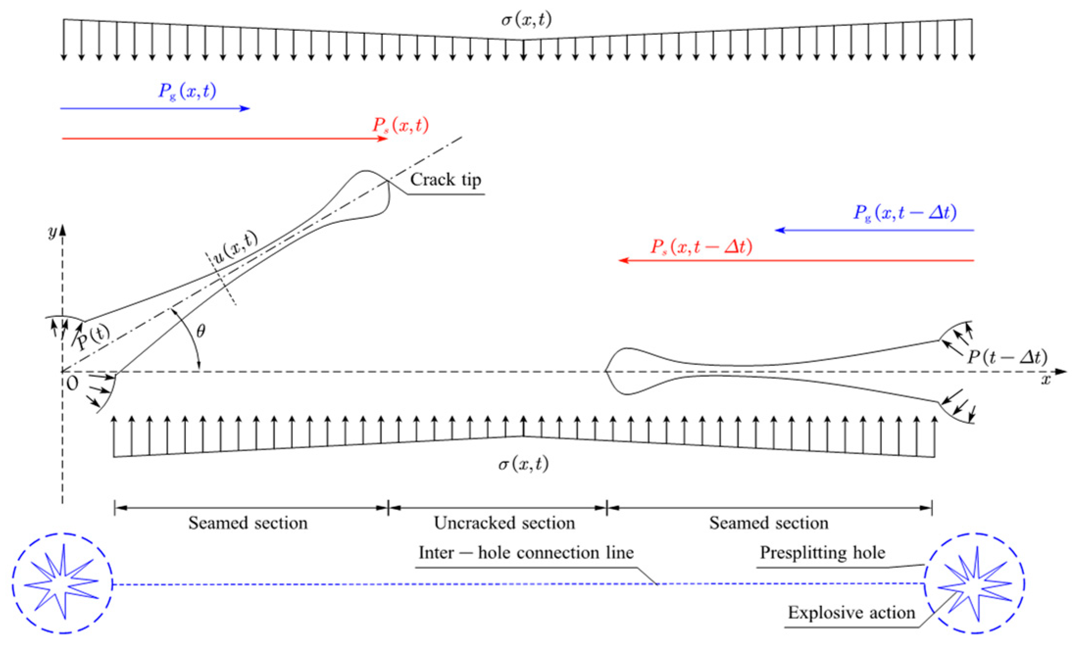
As theoretical calculations are not applicable in the event of discrete cracking of rocks, the present work firstly offers an equation for the description of cracking in type I tensile fractures between pre-cracked holes, as illustrated in Figure 4. It depicts a dynamic seaming model for presplitting blasting that takes the effect of inter-hole blasting into consideration. This analysis is based on elastic assumptions, primarily examining the crack propagation trend of type I tensile cracks in conjunction with the previously analyzed elastic stress fields (explosion shock and in situ stress). It also investigates the influence of adjacent explosion stress fields on existing cracks, without yet addressing elastoplastic behavior or complex crack failure mechanisms.
The dynamic stress intensity factor K I dyn t is employed to quantify the magnitude of the stress field near the crack tip under conditions where r → 0. It can be expressed by the following relation:
K I dyn t = lim r 0 2 π r σ y y r , 0 , t K I dyn t K I d
Here, K I d denotes the dynamic fracture toughness of the material. For crack initiation under explosive tensile loading in the presence of an initial stress field, the crack propagation driven by stress wave must overcome the closure effect caused by the initial stress, as described by the following criterion:
K dyn t = K s dyn t K s dyn t Δ t K σ dyn t K dyn t K I d
Here, K s dyn t represents the dynamic stress intensity factor at the crack tip induced solely by the stress wave, while K s dyn t Δ t denotes the component caused specifically by the stress wave from an adjacent blasthole. K σ dyn t is the contribution due to the in situ stress, and K dyn t corresponds to the resultant dynamic stress intensity factor after superposition of all components.
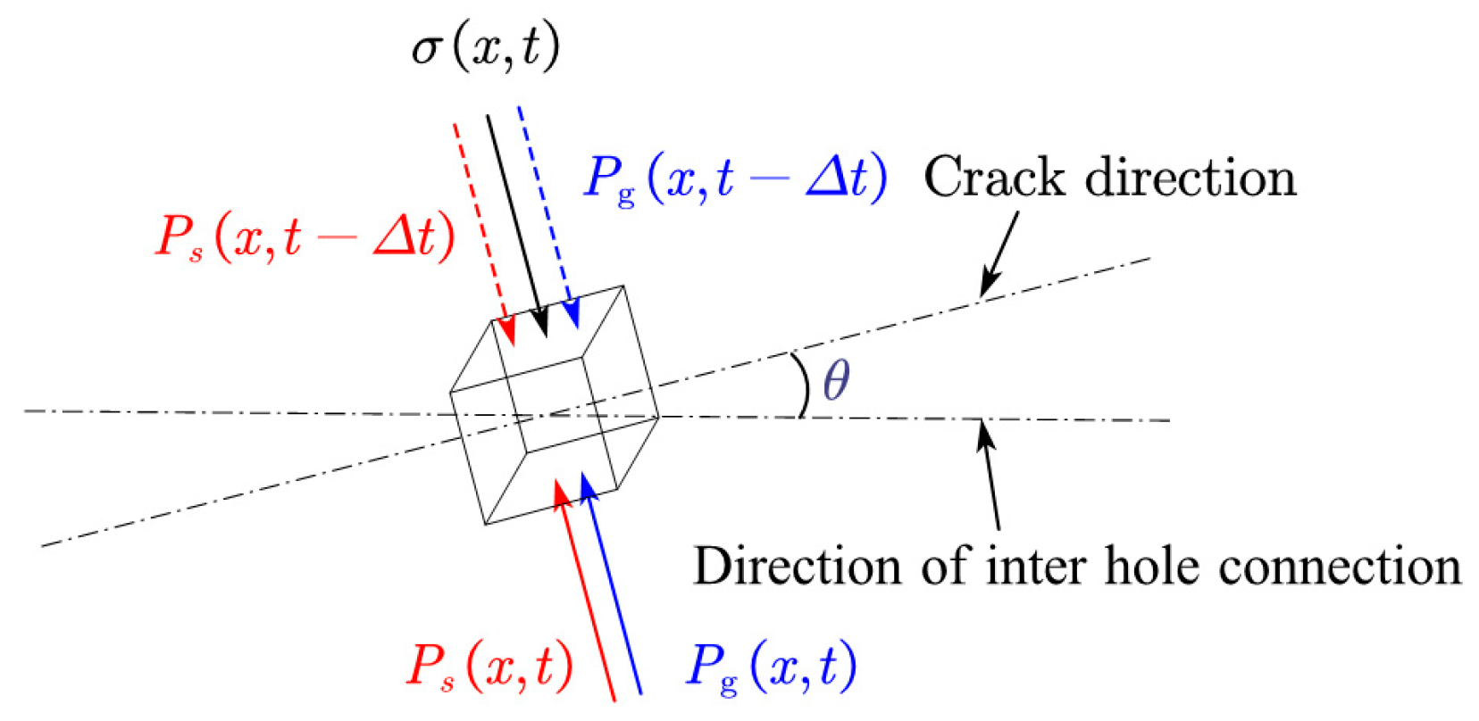
Owing to the distinctly earlier initiation of the blast-induced shock wave compared to the expansion of the gaseous products, a significant temporal phase shift exists between these two loading mechanisms. Moreover, the in situ stress field remains active throughout the processes of rock fracture and crack propagation. Consequently, the relative magnitude and timing of these three factors lead to variations in the dynamic crack propagation behavior. Figure 5 presents a stress analysis performed on a rock mass element at the crack surface, in the direction normal to the crack plane following crack initiation.
For the fractured section, variations in crack opening displacement can significantly influence the transmission and efficiency of explosive energy. The evolution of the crack aperture is governed by the stress conditions—specifically, the dynamic in situ stress σ x , t and the blast-induced loading P t —as well as the rock deformation characteristics. The blast loading applied to the surface rock mass element comprises two components: the residual hoop stress P s x , t resulting from the explosive stress wave and the hoop stress P g x , t due to the detonation gases’ pressure. The mechanical response of the rock unit on the fracture surface can be characterized by an equation that incorporates the effects of stress waves originating from adjacent blastholes.
σ x , t + P g x , t + P g x , t Δ t + P s x , t + P s x , t Δ t = f x , t
With reference to the unit acceleration analysis,
m a t / s = f x , t T d
The acceleration of the rock unit on the crack surface can be determined at any given time, from which its circumferential velocity and displacement may be derived, thereby capturing the complex evolution of crack opening.
As indicated by the foregoing analysis, during the formation of inter-hole cracks via presplitting blasting, the propagation of initial radially oriented cracks—induced by the blast—governs the inter-hole fracture process. Subsequent crack evolution occurs under the combined influence of the explosive stress wave, the pressure of detonation gases, and the dynamic in situ stress field. The mechanical model describing the dynamic crack process is represented by the following expression:
K s dyn t K s dyn t Δ t K σ dyn t K I d Crack tip ; σ x , t + P g x , t + P g x , t Δ t + P s x , t + P s x , t Δ t = f x , t Fractured section ;
Specifically, for the fracture extension of zone II3 and zone III in Figure 1, the neighboring hole blasting stress wave will clearly affect the dynamic crack expansion, which is more similar to the free-surface transmissive effect as the angle θ becomes closer to 90 degrees in Figure 5. Nevertheless, analytical solutions are only feasible for a limited number of idealized scenarios. In most practical cases, it is necessary to resort to numerical methods. Accordingly, this study utilizes a finite element approach to simulate the dynamic rock fracturing process under in situ stress conditions, investigate the law of dynamic crack propagation, and validate the theoretical model previously proposed.

3. Numerical Simulation

3.1. Numerical Model

The dynamic cracking process induced by inter-hole presplitting blasting was studied. To this end, a calculation model based on ANSYS/LS-DYNA for inter-hole presplitting blasting was established (see Figure 6). The model’s dimensions are 2.5 m × 1.5 m × 0.005 m (length × width × thickness). The model features two presplitting holes that are symmetrical in the medial plane, accompanied by a radial uncoupled charging structure. The spacing between holes was measured to be 0.8 m, with a diameter of 76 mm for each hole. The charge diameter was determined to be 32 mm. The rock type was identified as granite, and the explosive material used was emulsion explosive. The rock is designated as a Lagrange unit, while the explosive and air are classified as ALE units. The total number of mesh grids is approximately 163,000. For the purpose of facilitating the simulation, the initial damage to the rock caused by drilling is not taken into account in this calculation.

3.2. Parameter Selection and Verification

The precise parameters for the model are associated with granite rock, which is categorized as brittle rock. As demonstrated in Table 1, the material identity and parameters [36] are considered excellent for the purpose of characterizing the excavation disturbance dynamic behavior of hard, brittle rock.
To simulate explosive events, the Fluid Structure Coupling algorithm of LS-DYNA was employed to model the dynamic impact of explosives. The fundamental principle underlying this methodology is to facilitate the movement of materials within the grid. This enables the management of substantial deformation issues, including fluid flow and explosion impact, thereby ensuring the effective resolution of complex structural challenges. The material constitutive model MAT_HIGH_EXPLOSIVE_BURN and the Jones–Wilkins–Lee (JWL) equation are utilized to characterize the relationship between pressure and volume during explosive detonation. The equation is as follows [39]:
p = A HE 1 ω R 1 V e R 1 V + B HE 1 ω R 2 V e R 2 V + ω E V
where p is the pressure, V refers to the relative volume, and the parameters include AHE, BHE, R1, R2, and ω. The empirical constant of a certain type of explosive is determined by experiments. The parameters selected in this paper are shown in Table 2 below [40,41].
Owing to the decoupled charge configuration in presplitting blasting, the *MAT_NULL material model is employed to represent the air-filled interval. This model characterizes the pressure evolution in the air medium using a multilinear equation, given by
P = C 0 + C 1 μ + C 2 μ 2 + C 3 μ 3 + C 4 + C 5 μ + C 6 μ 2 E
where P is the air pressure, C 0 = C 1 = C 2 = C 3 = C 6 = 0 , C 4 = C 5 = 0.4 , μ = ρ / ρ 0 , ρ 0 and ρ are the initial density and current density of air, respectively, and the relevant parameters are shown in Table 3. PC is the pressure step truncation coefficient, MU is the dynamic viscosity coefficient, and C1~C6 are the polynomial equation coefficients.
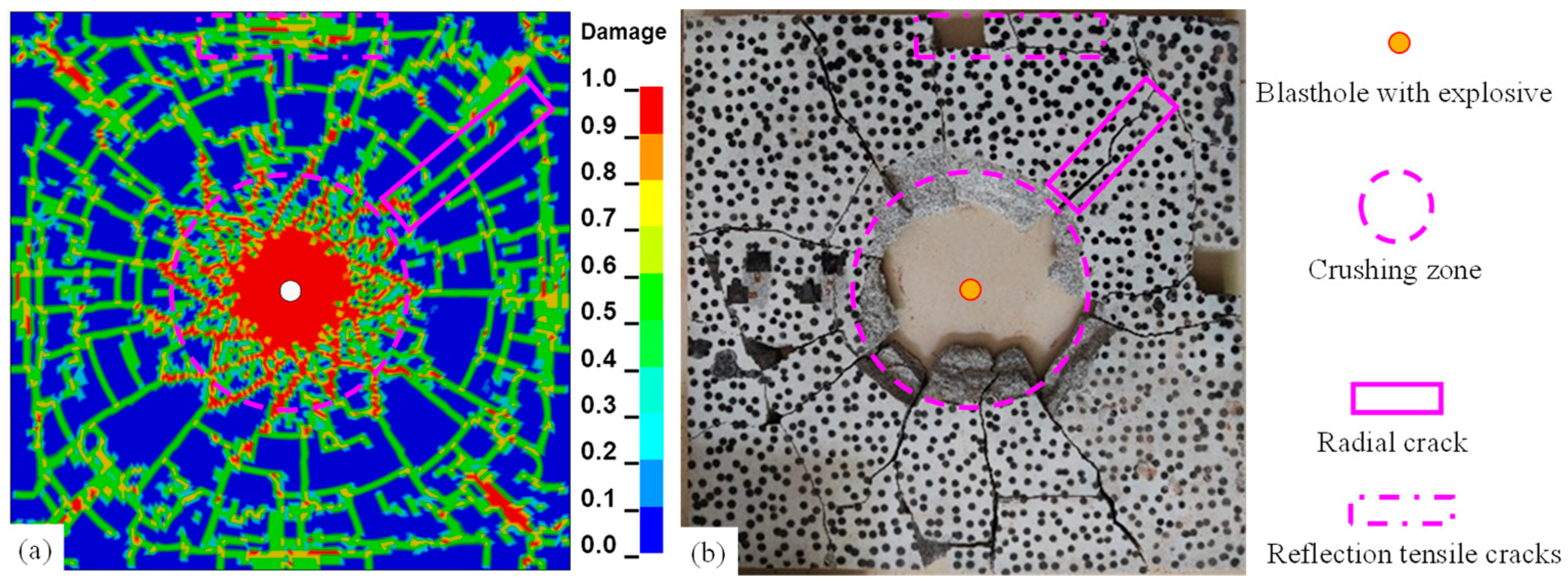
Additionally, blast damage testing was employed to confirm the validity of granite parameters. A granite slab measuring 40 cm × 40 cm × 2 cm was used for the test. A hole of 15 mm in diameter was drilled in the center of the slab, and it was then filled with 4 g of explosive while it was kept in a stress-free environment. The results are displayed in Figure 7, and it can be noted that the numerical simulation results under the current granite settings are largely comparable with the explosion test results. Both crushing zones have a diameter of about 15 cm, and they both have obvious radial cracks. As a result of the boundary’s reflection, there is also clear reflecting tensile damage near the boundary and clear circumferential cracks around 3~5 cm away from the boundary. These findings support the validity of the adopted granite parameters in characterizing cracking damage in granite rock under blast loading. Although the same rock type also exists, there is variation in parameters such as wave velocity, but it does not affect the overall hard and brittle rock law; the hard rock of dolomite and granite, as well as both the stress–strain curve and other properties or parameters exhibited by the damage characteristics and cracking law, is also similar [42,43,44].

3.3. Result Analysis

3.3.1. Dynamic Cracking Process of Inter-Hole Presplitting

Figure 8 depicts the pressure propagation and damage crack extension caused by double-hole blasting under a σ x = σ y = 10   MPa condition. The blast-generated pressure gradually decays with the continuous propagation of the blast shock wave, and after the superposition of the inter-hole stress field appears at about 86 μs, the crack continues to expand with the influence of the blast stress field of the neighboring hole. This result is consistent with the effects of propagation and superposition of porous explosive stress waves described in existing research results [45,46]. In terms of crack extension morphology, the cracks induced by a single blasthole exhibit uniform expansion in all directions prior to being influenced by adjacent holes, as illustrated at 50 μs and 86 μs in Figure 8. Additionally, the cracks between holes, whose expansion direction crosses the direction of the stress wave propagation at a larger angle, appear to a certain degree of extension length limit when affected by nearby hole stress wave propagation, such as 150 μs and 1 ms in Figure 8.
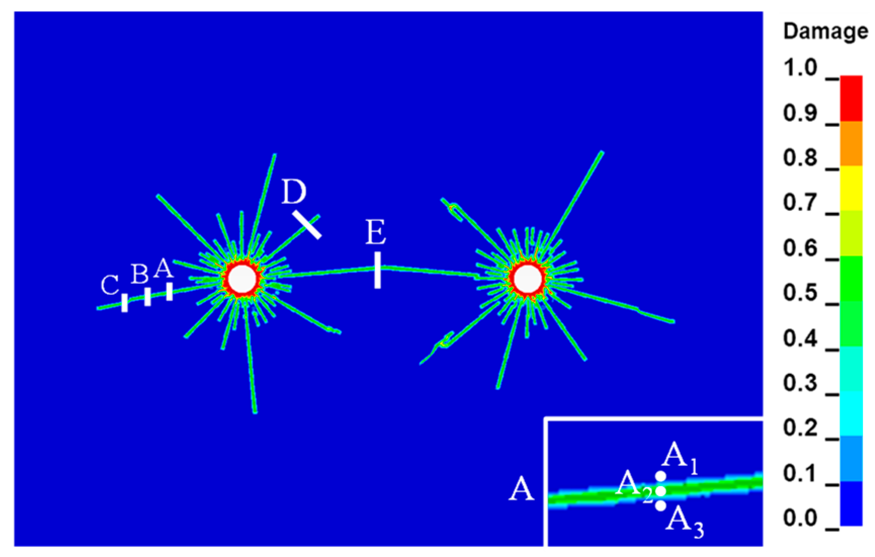
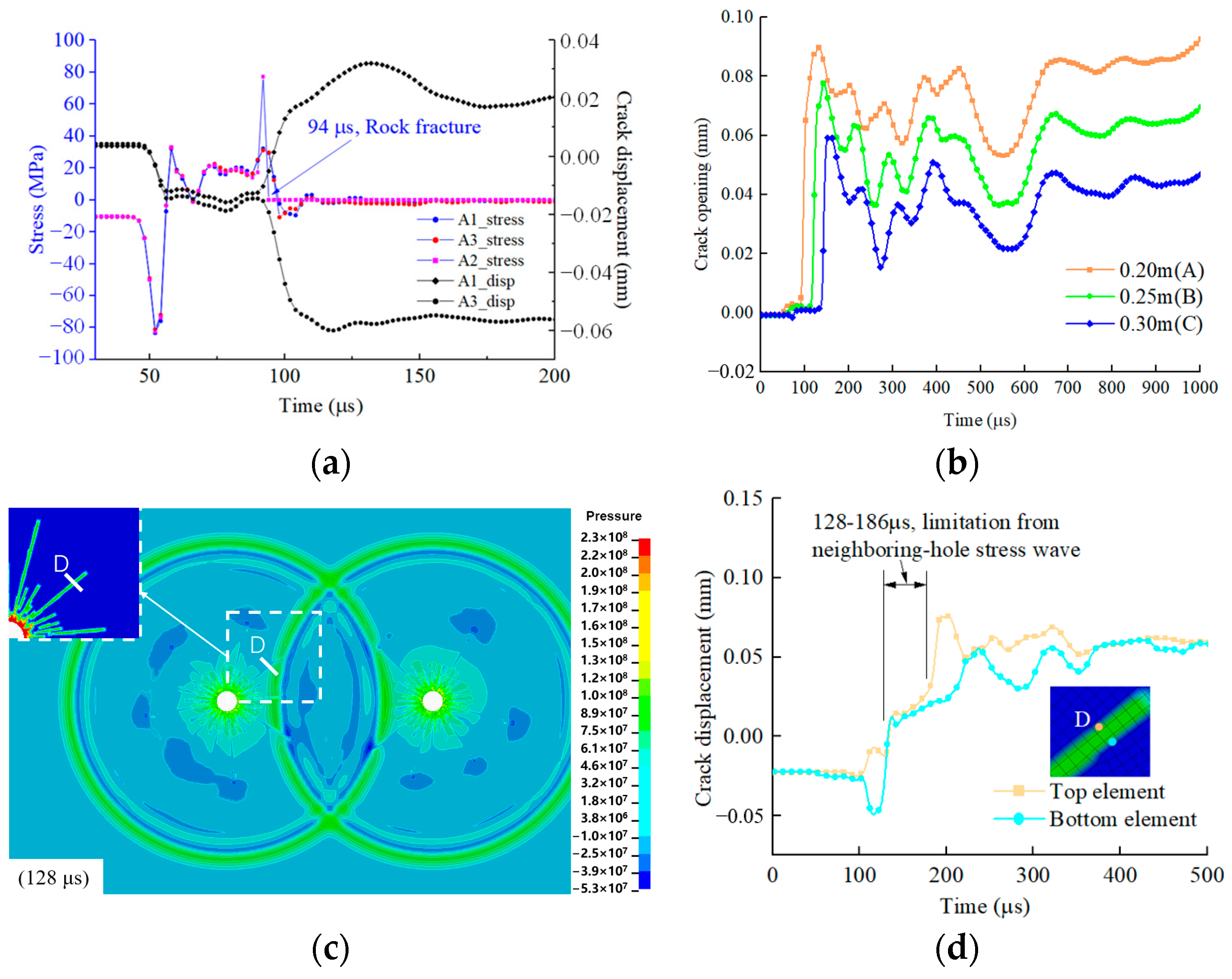
To investigate the dynamic propagation of presplitting blast-induced cracks between holes and the effect of adjacent blasts, monitoring sections A, D, and E were selected as representative cases. They correspond to outer cracks, non-penetrating cracks, and inter-hole penetration cracks, respectively. Sections A, B, and C represent burst distances of 0.20 m, 0.25 m, and 0.30 m, respectively, as shown in Figure 9.
Figure 10a firstly presents the displacement–time history of the crack unit and crack surface units on both sides of the crack. Additionally, it also shows the normal stress–time curve of section A. Upon rock fracture, the rock unit A2 experiences stress dynamic unloading, with the tensile stress quickly being unloaded to zero. In contrast, the adjacent rock units A1 and A3 experience a continued increase in tensile stress before rapidly unloading, transitioning to compressive stress, and eventually converging to an equilibrium state. For a crack outside the hole, Figure 10b depicts the progression of the crack opening at 0.20, 0.25, and 0.30 m from the center of gravity. The crack opening is rapidly opened in conjunction with the rock cracking process and rapid unloading of its unit stress, followed by a certain degree of rebound under the action of ground stress. And the crack opening subsequently continues to rise under the action of blast pressure. For section D, the adjacent hole blast shock wave clearly limits the crack opening, as illustrated in Figure 10c,d. At 128–186 µs, the crack opening where section D is located is squeezed closed and stops extending.

3.3.2. Influence of Stress Conditions on Inter-Hole Cracking Process

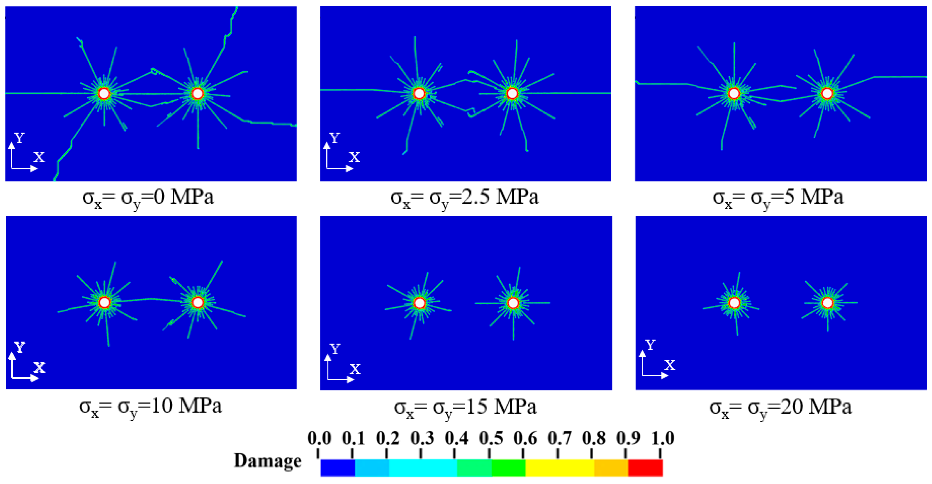
The complex in situ stress conditions present at the actual engineering sites significantly influence the inter-hole crack expansion of presplitting blasting. As shown in Figure 11, the crack patterns resulting from inter-hole blasting under various in situ stress environments are presented. It is discovered that when the stress level increases from 0 MPa to 20 MPa, the crack expansion reduces from about 0.75 m to 0.24 m. The inter-hole crack expansion range is lower than the crack expansion range on the exterior of the hole due to the influence of the adjacent hole stress wave, especially under lower stress levels (Figure 12). Under medium–high stress, however, the inhibitory impact of neighboring hole stress waves from adjacent holes on inter-hole fractures is reduced. Cracks around the blasthole consequently exhibit a confined pattern of uniform expansion.
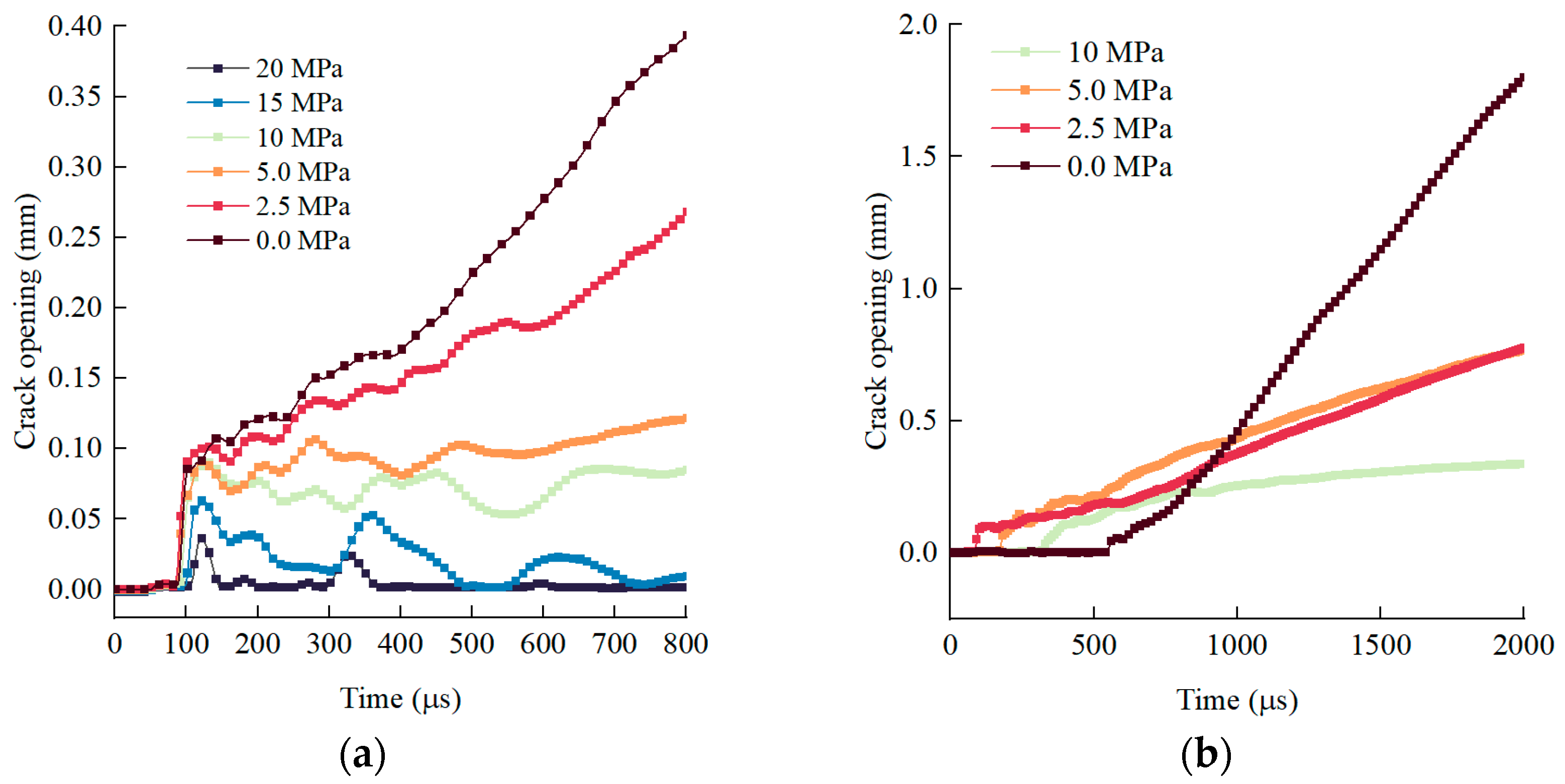
For the dynamic crack expansion process (Figure 13), they are essentially consistent with the previous results under σ x = σ y = 10   MPa . For unpenetrated cracks outside the holes (Figure 13a), as the ground stress level increases, the maximum value of the initial crack opening appears significantly lower, and the crack unloading rebound increases strongly, and then tends to close. Once a crack initiates and coalesces at the midpoint between two blastholes, the crack apertures typically increase during this process, forming a penetrated crack. And the lower the ground stress, the greater the openings (Figure 13b).
Furthermore, Figure 14 illustrates fracture propagation at various lateral pressure coefficients for a blasting center distance of 0.3 m. A higher lateral pressure coefficient results in longer crack extension along the direction of maximum principal stress. These cracks also exhibit larger apertures during dynamic propagation, indicating more efficient blast energy transmission. At lateral pressure coefficients ranging from 1.3 to 4.0, the inter-hole cracks appeared as penetrated, curved interlayer, and unpenetrated, respectively. And as the lateral pressure coefficient increases, the crack opening becomes higher.

3.3.3. Influence of Blasting Delay Time on Inter-Hole Cracking Process

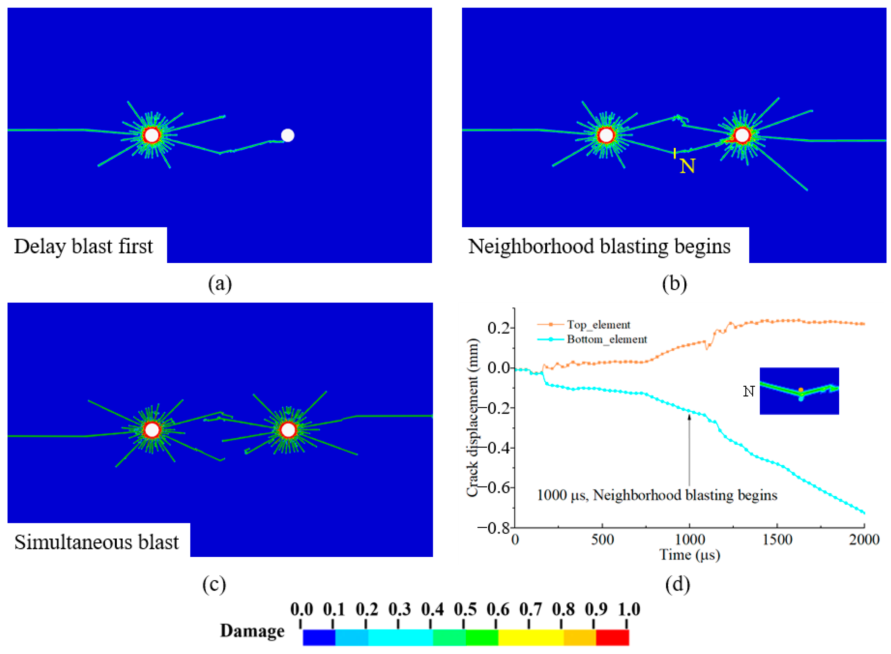
The primary goal of presplitting blasting includes vibration isolation and crack resistance, particularly in high in situ stress conditions. Given the superiority of larger lateral pressure coefficients for inter-hole crack penetration, a simulated crack formation of presplitting blasting with a two-hole model was performed under σ x = 20   MPa ,   σ y = 0   MPa to investigate the effect of blast delay time on the dynamic seam formation process, distribution pattern, and generated vibration between holes. Due to the numerical modeling, where the left hole did not crack continually and clearly after 1 ms, the right hole detonation delay is set to account for this in the numerical analysis.
Figure 15 compares the crack dynamic expansion under delayed and simultaneous presplitting blasting conditions. In the case of simultaneous detonation (Figure 15c), cracks sprout and spread around both holes in the direction of the major stresses, eventually intersecting midway. The crack patterns of the two holes are basically symmetrical along the centerline of the holes. Under delayed detonation, the left hole explosion first induces cracks gradually in all directions more uniformly and extends to the right hole (Figure 15a). Upon detonation of the right hole, the damage was intensified at the fractures previously generated from the left hole, and the width of the penetration cracks was greatly enlarged (Figure 15d). Notably, large-angle cracks from the right hole between holes essentially did not appear, in addition to the intersection penetration of the existing cracks on the left hole (Figure 15b). The fact that the outside of the hole is essentially the same as the left side helps to explain the induction of existing cracks’ role in the explosion. Given the constraints of numerical modeling for finite element characterization following rock cracking, an explosive test will be conducted to further examine the molding effect of delayed presplitting blasting.

4. Inter-Hole Explosion Verification Test

To verify the influence of in situ stress on crack propagation and the effects of adjacent blasts, explosion tests were conducted under uniaxial loading conditions. Firstly, rock cracking is given for single-hole blasting in a uniaxial stress environment of 3 MPa. The dynamic crack extension effect and molding control discrepancies between holes are subsequently demonstrated using millisecond blasting under uniaxial stress. The size of the granite samples is 400 mm × 400 mm × 18 mm. Stress boundaries are achieved by one or two hydraulic jacks, as well as two uniform steel plates and steel structures, as shown in Figure 16. When there is no need to apply pressure in a certain direction, the jack is just in contact with the rock slab, resulting in a fixed limitation and no stress loading. Strain gauges are mainly used for dynamic monitoring of rock samples.
(1) Single-hole explosion test: A hole was drilled in the center with a hole diameter of 15 mm, and emulsion explosives were used with 2.5 g (Figure 16c,d).
(2) Multi-hole explosion test: Three blastholes with a hole diameter of 15 mm were drilled. Two of them have presplitting blastholes spaced 100 mm apart and symmetrical to the slab’s center. Following presplitting holes, the third hole is made up of side blasting holes to test the crack-resistant effect of inter-hole seam formation (Figure 16e,f). Emulsion explosives were used with 2 g explosives in the presplitting hole and 2.5 g explosives in the side blasting hole. Two sets of tests were designed according to different blasting delay times.
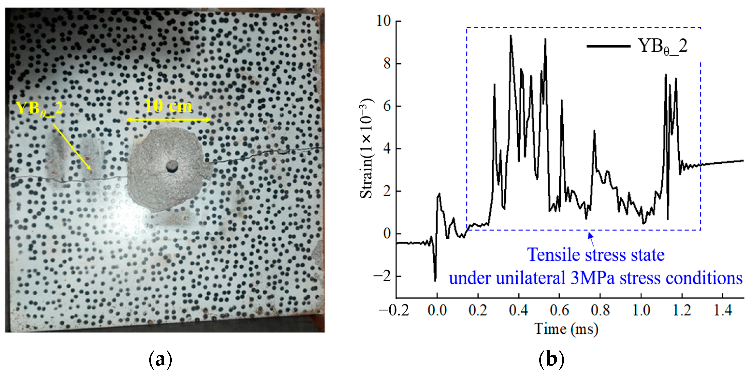
Firstly, Figure 17 illustrates the crack pattern resulting from single-hole blasting under 3 MPa uniaxial stress. The results indicate that the unidirectional principal stress predominantly governs the direction of the crack extension. A through crack with a width of approximately 1 mm forms in the principal stress’s direction, and a surface spalling range with a radius of approximately 5 cm forms in the blasthole’s proximal area. Because the location of the strain gauges mentioned above is essentially close to the explosion, some of them were destroyed in the explosion. The crack extension circumferential stress curve obtained by monitoring YBθ_2 (bursting center distance of approximately 10 cm, circumferential arrangement) is provided here. After the initial compression and tensile action, a considerable tensile stress condition was exhibited. This finding is also compatible with the numerical simulation of crack opening with the continuous action of tensile stress, as described previously.
In the multi-hole explosion test, comparative blasting designs are shown in Table 4. Given that the explosion at the site severely destroyed the strain-gauge monitoring lines, the following analysis is primarily focused on post-blast impacts.
Figure 18 illustrates the blasting effects observed in rock plate cracking under simultaneous presplitting blasting. In this configuration, radial cracks propagate radially from the presplitting holes in multiple directions, leading to a significant enhancement in the fragmentation of the reserved rock mass on both sides. Compared to single-hole blasting scenarios discussed earlier, the control over principal stress direction appears to exert less influence on crack guidance in simultaneous presplitting blasting. The phenomenon is attributed to the superposition of stress waves from simultaneous dual-hole detonation, wherein the explosive action in the rock mass between the holes is significantly amplified. This enhanced inter-hole fragmentation overwhelms the crack guidance capability of the comparatively low in situ stress field (3 MPa), thus negating any distinct advantage for crack propagation along the major principal stress direction. Specifically, in zone III, located between the two presplitting holes, cracks originating from the right hole did not extend into this region. Instead, Crack 1 initially developed toward the inter-hole region and subsequently diverged outward, while Crack 2 extended at a considerable angle relative to the connecting line between holes, eventually propagating toward side hole 3. In contrast, the left presplitting hole experienced complete failure, with fractured material ejected toward the left free surface. This crack propagation pattern aligns well with the outcomes of the numerical simulation of simultaneous detonation presented earlier, which predicted shorter crack lengths between holes compared to outward directions, or outward deflection of inter-hole cracks. These observations effectively demonstrate the dynamic interaction between stress waves generated by adjacent blastholes and their inhibiting effect on crack development within the inter-hole region.
Figure 19 shows the blasting effect of rock plate cracking under millisecond blasting designs. Well-defined through-going cracks are observed along the direction of the connecting line between holes (the direction of the large principal stress). In contrast, the rock mass remains intact in the direction of the minor principal stress, with no evidence of cracking induced by presplitting. It indicates an effective presplitting outcome. Meanwhile, the pre-cracks formed by millisecond blasting could effectively block the influence of adjacent blasting holes on the retained rock mass, and the retained rock mass has good integrity without obvious fractures.
As a result, based on the ability to achieve rock cracking, millisecond blasting can reduce the impact of blasting stress waves, allowing for the expansion of inter-hole cracks along the direction of the main stress, whereas simultaneous blasting may cause the superposition of stress waves to become the main influence on crack expansion, and pre-cracking control in a seam does not fit.
Due to the limited number of tests conducted in this study, the results may be subject to chance variations. Additional experiments will therefore be conducted in the future to investigate the dynamic propagation of cracks. At the same time, the experimental process above used high-speed photography for monitoring. However, due to the explosive detonation process accompanied by a large amount of smoke and dust, the sight of high-speed photographic monitoring was blocked. It cannot achieve effective experimental monitoring of the dynamic expansion of cracks in the near-area blast. These challenges will be addressed in subsequent experimental studies.
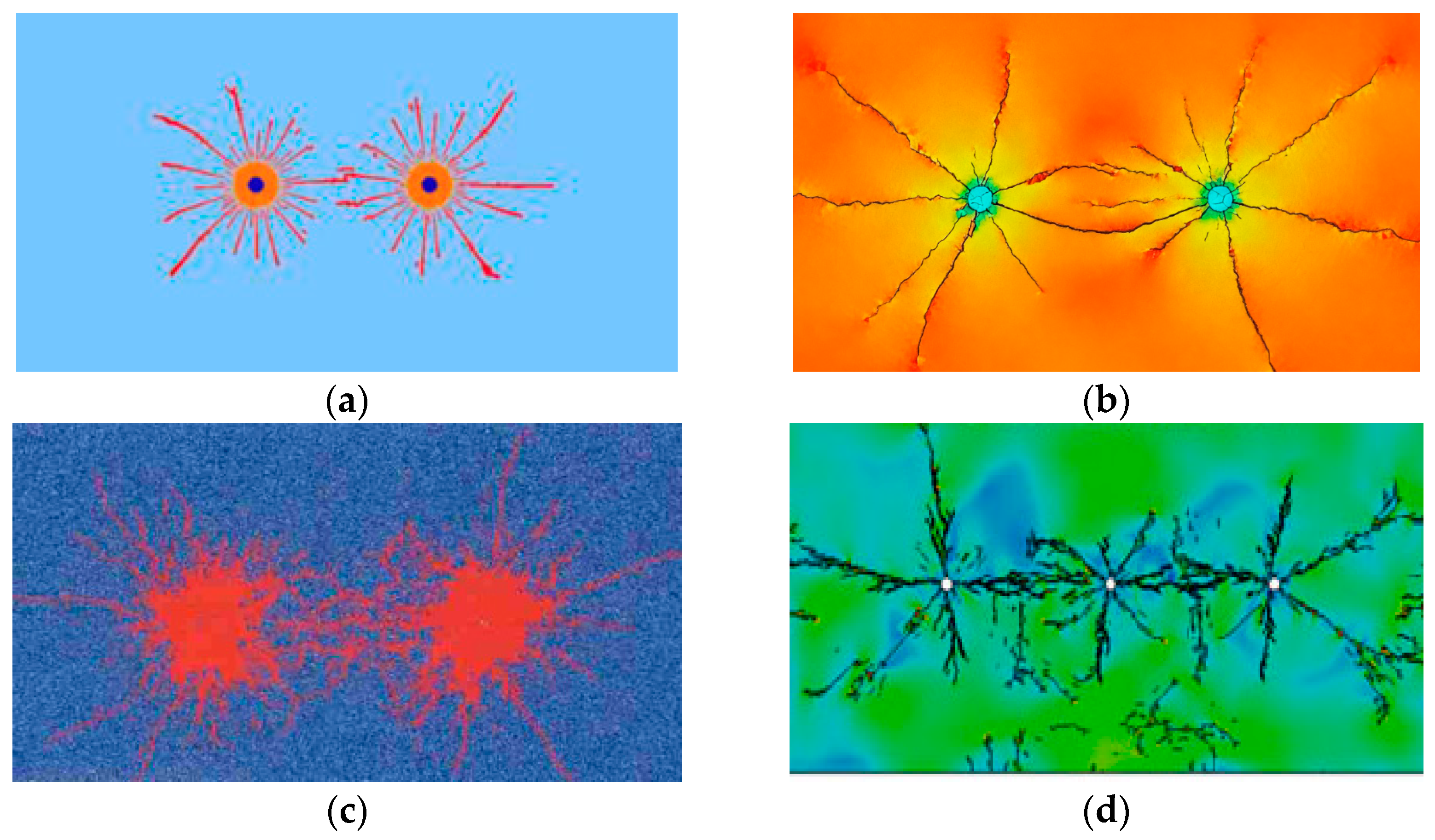
To demonstrate the validity and novelty of the conclusions, the findings are compared and discussed with those of other researchers [23,28,47,48], as shown in Figure 20. These results align with the crack distribution characteristics induced by dual-hole (multi-hole) blasting in existing studies, as can be observed. Specifically, crack propagation length is significantly shorter at large angles between holes than at the outer sides of the two holes. This indicates that explosive stress waves between holes have a pronounced influence on crack propagation. While prior studies have focused on crack morphology, they have not yet conducted in-depth investigations into the differences between inter- and extra-hole cracks. This paper, however, explores the mechanism by which explosive stress waves influence the dynamic propagation of pre-existing cracks, thereby demonstrating the innovation of the work and the validity of its conclusions.

5. Conclusions

To investigate the dynamic cracking mechanism between presplitting holes in deep rock, a theoretical model was first established to analyze the inter-hole cracking process. Numerical simulations were then employed to examine the dynamic cracking behavior under various stress conditions, revealing the influence mechanism of stress waves from adjacent holes on crack propagation. Furthermore, blasting tests involving single and multiple holes were conducted, which verified the dynamic expansion patterns of inter-hole fractures and demonstrated the significant advantages of micro-deferential blasting in presplitting applications. The main conclusions are as follows:
(1) High ground stress, blast stress waves, and blast-generated gas all affect the dynamic cracking process of multi-hole blasting, and the suggested two-hole dynamic crack model may well depict the dynamic effects of stress waves from adjacent holes on crack expansion. The fracture opening shows a dynamic change law of increasing, then decreasing, and then increasing again.
(2) Neighboring hole stress waves can have a major restricting effect on dynamic fracture opening, particularly for inter-hole fractures that cross the inter-hole line at a wide angle, resulting in a restricted propulsive effect of burst-generated energy on fracture expansion.
(3) One of the most crucial ways to achieve good pre-cracking in complex stress fields is to align the direction of the local maximum principal stress with the direction of inter-hole cracking. Additionally, delay blasting can be used to improve the cracking base for the expansion and connection of cracks in neighboring holes. This further demonstrates the practicality of delay blasting.
This work was conducted using a combined approach of elasticity theory, numerical simulation, and explosion testing. The theoretical model still exhibits significant discrepancies with field conditions, and its completeness requires further refinement through future research on complex crack geometries and three-dimensional crack propagation.

Author Contributions

Conceptualization, X.L. and P.Y.; methodology, X.L.; software, X.Y.; validation, J.Z. and X.Z.; formal analysis, C.Z.; writing—original draft preparation, X.L.; writing—review and editing, W.L. and M.C.; visualization, Y.W.; supervision, G.W.; project administration, P.Y.; funding acquisition, X.L., P.Y. and W.L. All authors have read and agreed to the published version of the manuscript.

Funding

The authors gratefully appreciate the support from the National Natural Science Foundation of China (No. 52379108), 2023 Postdoctoral Innovative Research Positions in Hubei Province (Postdoctoral No. 325469), and the Key Program of the National Natural Science Foundation of China (No. 51939008). The support from the National Natural Science Foundation of China (Grant No. 52109164) is also appreciated.

Institutional Review Board Statement

Not applicable.

Informed Consent Statement

Not applicable.

Data Availability Statement

The original contributions presented in this study are included in the article. Further inquiries can be directed to the corresponding author.

Conflicts of Interest

The authors declare no conflicts of interest.

References

  1. Li, X.; Huang, J.; Luo, Y.; Dong, Q.; Li, Y.; Wan, Y.; Liu, T. Numerical simulation of blast vibration and crack forming effect of rock-anchored beam excavation in deep underground caverns. Shock Vib. 2017, 2017, 1812080. [Google Scholar] [CrossRef]
  2. Zhang, T.; Huang, J.; Li, X.; Liu, T.; Bian, X.; Luo, Y. Characteristics of the elevation amplification effect of vibration velocity in rock surrounding underground cavities under different stress conditions. Soil Dyn. Earthq. Eng. 2023, 165, 107704. [Google Scholar] [CrossRef]
  3. Fan, Y.; Yang, G.D.; Cui, X.Z.; Zhao, X.H.; Wu, J.G.; Wang, L.H. Low-Frequency Characteristics of Vibrations Induced by Transient Unloading of In Situ Stress and Its Influence on Safety of a Deeply Buried Tunnel. Int. J. Geomech. 2024, 24, 04023288. [Google Scholar] [CrossRef]
  4. Banadaki, M.D.; Mohanty, B. Numerical simulation of stress wave induced fractures in rock. Int. J. Impact Eng. 2012, 40, 16–25. [Google Scholar] [CrossRef]
  5. Saadatmand Hashemi, A.; Katsabanis, P. The effect of stress wave interaction and delay timing on blast-induced rock damage and fragmentation. Rock Mech. Rock Eng. 2020, 53, 2327–2346. [Google Scholar] [CrossRef]
  6. Fan, Y.; Chen, J.; Leng, Z.; Yang, G.; Liu, X.; Tian, B. Punching Mechanism of Air-Deck Stemming for Drilling Blasting and Its Influence on Rock Fragmentation. Rock Mech. Rock Eng. 2024, 57, 3917–3935. [Google Scholar] [CrossRef]
  7. Córdova, E.; Gottreux, I.; Anani, A.; Ferrada, A.; Contreras, J. Blasting and preconditioning modelling in underground cave mines under high stress conditions. J. S. Afr. Inst. Min. Metall. 2021, 121, 71–80. [Google Scholar] [CrossRef]
  8. Sanchidrián, J.A.; Segarra, P.; López, L.M. Energy components in rock blasting. Int. J. Rock Mech. Min. 2007, 44, 130–147. [Google Scholar] [CrossRef]
  9. Ye, Z.; Chen, M.; Yi, C.; Lu, W.; Yan, P. Quantitative Study of the Action on Rock Mass Failure under the Shock Wave and Gas Pressure in Bench Blasting. Int. J. Geomech. 2023, 23, 04023135. [Google Scholar] [CrossRef]
  10. Trivino, L.F.; Mohanty, B. Assessment of crack initiation and propagation in rock from explosion-induced stress waves and gas expansion by cross-hole seismometry and FEM–DEM method. Int. J. Rock Mech. Min. Sci. 2015, 77, 287–299. [Google Scholar] [CrossRef]
  11. Hino, K. Fragmentation of rock through blasting and shock wave theory of blasting. In Proceedings of the 1st US Symposium on Rock Mechanics (USRMS), Golden, CO, USA, 23–25 April 1956. [Google Scholar]
  12. Sazid, M.; Singh, T.N. Two-dimensional dynamic finite element simulation of rock blasting. Arab. J. Geo-Sci. 2013, 6, 3703–3708. [Google Scholar] [CrossRef]
  13. Langefors, U.; Kihlström, B. The Modern Technique of Rock Blasting; Wiley: New York, NY, USA, 1963; Volume 405. [Google Scholar]
  14. Langefors, U. Fragmentation in rock blasting. In Proceedings of the 7th Symp. on Rock Mechanics, Pennsylvania State University, University Park, PA, USA, 14–16 June 1965; pp. 1–21. [Google Scholar]
  15. Kutter, H.K.; Fairhurst, C. On the fracture process in blasting. Int. J. Rock Mech. Min. Sci. 1971, 8, 181–202. [Google Scholar] [CrossRef]
  16. Hagan, T.N. Rock breakage by explosives. Acta Astronaut. 1979, 6, 329–340. [Google Scholar] [CrossRef]
  17. Dally, J.W.; Fourney, W.L.; Holloway, D.C. Influence of containment of the bore hole pressures on explosive induced fracture. Int. J. Rock Mech. Min. Sci. 1975, 12, 5–12. [Google Scholar] [CrossRef]
  18. Larocque, G.; Favreau, R. Blasting research at the Mines Branch. In Proceedings of the 12th US Symposium on Rock Mechanics (USRMS), Rolla, MO, USA, 16–18 November 1970. [Google Scholar]
  19. Rossmanith, H.; Daehnke, A.; Nasmillner, R.; Kouzniak, N.; Ohtsu, M.; Uenishi, K. Fracture mechanics applications to drilling and blasting. Fatigue Fract. Eng. Mater. Struct. 1997, 20, 1617–1636. [Google Scholar] [CrossRef]
  20. Daehnke, A.; Rossmanith, H.; Knasmillner, R. Blast-induced dynamic fracture propagation. In Rock Fragmentation by Blasting; CRC Press: Boca Raton, FL, USA, 2020; pp. 13–18. [Google Scholar]
  21. Duvall, W.I.; Petkof, B. Spherical Propagation of Explosion-Generated Strain Pulses in Rock; US Department of the Interior, Bureau of Mines: Washington, DC, USA, 1959.
  22. Yi, C.; Johansson, D.; Nyberg, U.; Beyglou, A. Stress Wave Interaction Between Two Adjacent Blast Holes. Rock Mech. Rock Eng. 2016, 49, 1803–1812. [Google Scholar] [CrossRef]
  23. Ding, C.; Yang, R.; Feng, C. Stress wave superposition effect and crack initiation mechanism between two adjacent boreholes. Int. J. Rock Mech. Min. Sci. 2021, 138, 104622. [Google Scholar] [CrossRef]
  24. Zhang, X.; Yan, P.; He, H.; Lu, W.; Liu, B.; Zhu, J.; Cheng, Y. Experimental investigations of the effect of millisecond-delay time on the blast vibration reduction with electronic detonators. J. Vib. Control. 2023, 29, 4204–4215. [Google Scholar] [CrossRef]
  25. Yi, C.; Sjöberg, J.; Johansson, D.; Petropoulos, N. A numerical study of the impact of short delays on rock fragmentation. Int. J. Rock Mech. Min. 2017, 100, 250–254. [Google Scholar] [CrossRef]
  26. He, C.; Chen, D.; Xiao, J.; Lu, L.; Guo, Z. Experimental study of crack propagation and failure around a horseshoe tunnel during nearby blasting. Int. J. Rock Mech. Min. Sci. 2021, 139, 104628. [Google Scholar] [CrossRef]
  27. Yang, L.; Wang, Q.; Xu, L.; Yang, R.; Chao, Y.J. Fracture path of cracks emigrating from two circular holes under blasting load. Theor. Appl. Fract. Mech. 2020, 108, 102559. [Google Scholar] [CrossRef]
  28. Pu, C.; Yang, X.; Zhao, H.; Chen, Z.; Xiao, D. Numerical investigation on crack propagation and coalescence induced by dual-borehole blasting. Int. J. Impact Eng. 2021, 157, 103983. [Google Scholar] [CrossRef]
  29. Xu, P.; Yang, R.; Guo, Y.; Chen, C.; Yang, Y.; Zuo, J. Investigation of the interaction mechanism of two dynamic propagating cracks under blast loading. Eng. Fract. Mech. 2022, 259, 108112. [Google Scholar] [CrossRef]
  30. Li, X.; Liu, K.; Qiu, T.; Sha, Y.; Yang, J. Study of presplit blasting under high in-situ stress. Eng. Fract. Mech. 2023, 288, 109360. [Google Scholar] [CrossRef]
  31. Li, X.; Liu, K.; Yang, J.; Qiu, T.; Sha, Y. Effects of in-situ stress on rock cracking in presplit blasting. Comput. Geotech. 2024, 168, 106124. [Google Scholar] [CrossRef]
  32. Liu, K.; Li, X.; Huang, L.; Sha, Y.; Yang, J.; Zhao, X.; Ma, S.; Hong, Z. Investigation on Rock Fracturing in Presplit Blasting Under Various Initial Stresses. Rock Mech. Rock Eng. 2024, 57, 6927–6950. [Google Scholar] [CrossRef]
  33. Yang, L.; Yang, A.; Chen, S.; Fang, S.; Huang, C.; Xie, H. Model experimental study on the effects of in situ stresses on pre-splitting blasting damage and strain development. Int. J. Rock Mech. Min. 2021, 138, 104587. [Google Scholar] [CrossRef]
  34. Yang, L.; Chen, S.; Yang, A.; Huang, C.; Xie, H. Numerical and experimental study of the presplit blasting failure characteristics under compressive stress. Soil Dyn. Earthq. Eng. 2021, 149, 106873. [Google Scholar] [CrossRef]
  35. Liu, X.; Yan, P.; Lu, W.; Lu, A.; Zhang, X.; Chen, M.; Wang, G. Numerical investigation of an improved deep-hole presplitting method based on notched blasting for deep-buried high sidewall structures. J. Build. Eng. 2023, 70, 106310. [Google Scholar] [CrossRef]
  36. Liu, K.; Li, Q.; Wu, C.; Li, X.; Li, J. Optimization of spherical cartridge blasting mode in one-step raise excavation using pre-split blasting. Int. J. Rock Mech. Min. 2020, 126, 104182. [Google Scholar] [CrossRef]
  37. Liu, K.; Li, X.; Hao, H.; Li, X.; Sha, Y.; Wang, W.; Liu, X. Study on the raising technique using one blast based on the combination of long-hole presplitting and vertical crater retreat multiple-deck shots. Int. J. Rock Mech. Min. 2019, 113, 41–58. [Google Scholar] [CrossRef]
  38. Dubner, H.; Abate, J. Numerical Inversion of Laplace Transforms by Relating Them to the Finite Fourier Cosine Transform. J. ACM 1968, 15, 115–123. [Google Scholar] [CrossRef]
  39. Hallquist, J. LS-DYNA Theory Manual 19. Livermore Software Technology Corporation (LSTC); ANSYS Inc.: Canonsburg, PA, USA, 2019. [Google Scholar]
  40. Kucewicz, M.; Baranowski, P.; Małachowski, J.; Trzciński, W.; Szymańczyk, L. Numerical Modelling of Cylindrical Test for Determining Jones—Wilkins—Lee Equation Parameters. In Proceedings of the 14th International Scientific Conference: Computer Aided Engineering, CAE 2018; Rusiński, E., Pietrusiak, D., Eds.; Lecture Notes in Mechanical Engineering. Springer: Cham, Switzerland, 2019. [Google Scholar] [CrossRef]
  41. Baranowski, P.; Kucewicz, M.; Gieleta, R.; Stankiewicz, M.; Konarzewski, M.; Bogusz, P.; Pytlik, M.; Małachowski, J. Fracture and fragmentation of dolomite rock using the JH-2 constitutive model: Parameter determination, experiments and simulations. Int. J. Impact Eng. 2020, 140, 103543. [Google Scholar] [CrossRef]
  42. Kang, P.; Zhaopeng, L.; Quanle, Z.; Zhenyu, Z.; Jiaqi, Z. Static and dynamic mechanical properties of granite from various burial depths. Rock Mech. Rock Eng. 2019, 52, 3545–3566. [Google Scholar] [CrossRef]
  43. Kucewicz, M.; Baranowski, P.; Małachowski, J. Determination and validation of Karagozian-Case Concrete constitutive model parameters for numerical modeling of dolomite rock. Int. J. Rock Mech. Min. Sci. 2020, 129, 104302. [Google Scholar] [CrossRef]
  44. Liu, X.; Yan, P.; Lu, W.; Zhu, J.; Zhang, X.; Lu, A.; Chen, M.; Wang, G. Investigation of dynamic crack formation mechanism based on a new crack dynamic driving model. Comput. Geotech. 2023, 159, 105471. [Google Scholar] [CrossRef]
  45. Sazid, M.; Singh, T.N. Numerical assessment of spacing–burden ratio to effective utilization of explosive energy. Int. J. Min. Sci. Technol. 2015, 25, 291–297. [Google Scholar] [CrossRef]
  46. Tao, J.; Yang, X.-G.; Li, H.-T.; Zhou, J.-W.; Fan, G.; Lu, G.-D. Effects of in-situ stresses on dynamic rock responses under blast loading. Mech. Mater. 2020, 145, 103374. [Google Scholar] [CrossRef]
  47. Yuan, W.; Liu, S.; Wang, W.; Su, X.; Li, Z.; Li, J.; Wen, L.; Chang, J.; Sun, X. Numerical study on the fracturing mechanism of shock wave interactions between two adjacent blast holes in deep rock blasting. Earthq. Eng. Eng. Vib. 2019, 18, 735–746. [Google Scholar] [CrossRef]
  48. Fukuda, D.; Moriya, K.; Kaneko, K.; Sasaki, K.; Sakamoto, R.; Hidani, K. Numerical simulation of the fracture process in concrete resulting from deflagration phenomena. Int. J. Fract. 2013, 180, 163–175. [Google Scholar] [CrossRef]
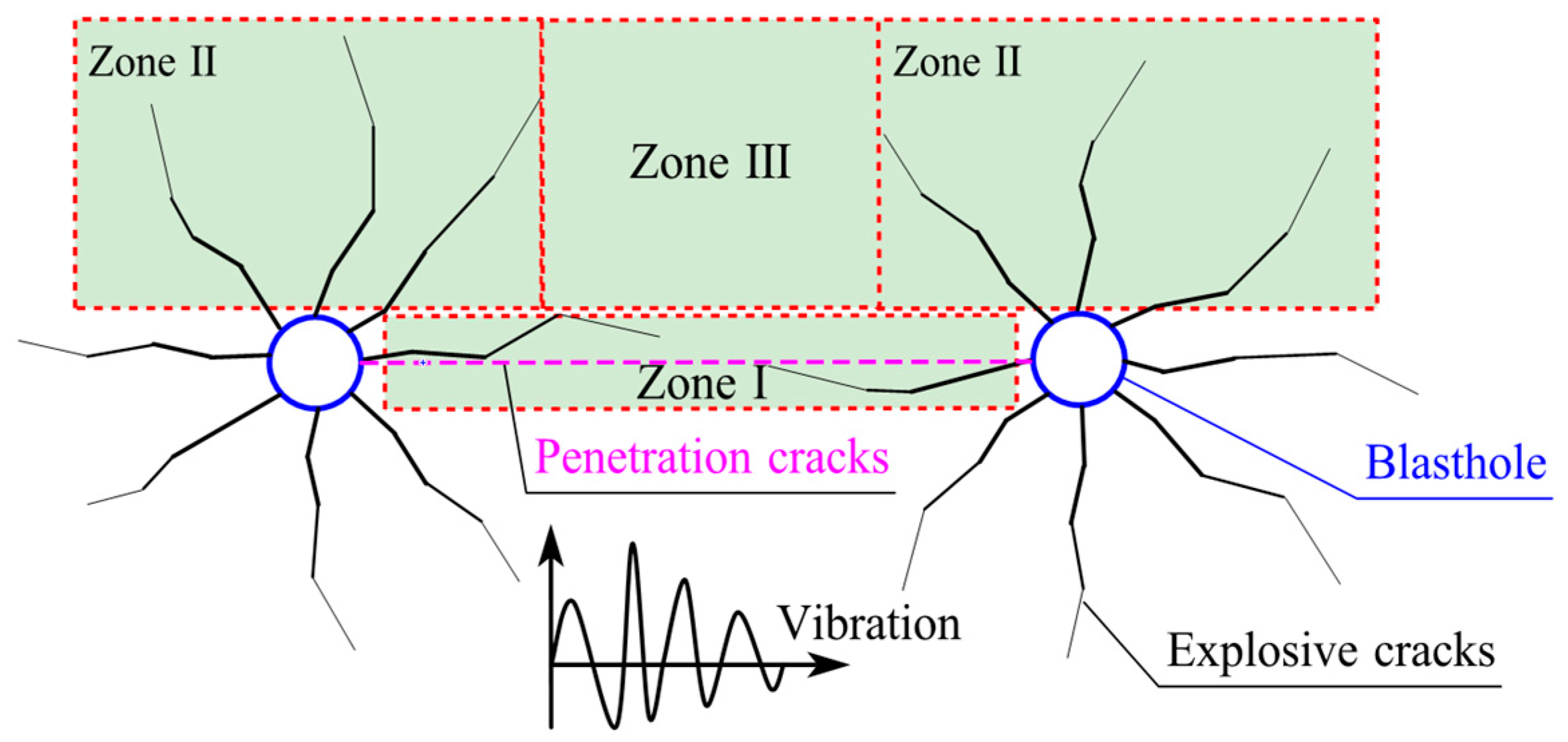
Figure 1. Crack extension zones for inter-hole presplitting or blast crushing.
Applsci 15 10036 g001
Figure 2. Stress–time history of typical in-hole detonation: (a) double-hole blasting action model; (b) blasting load curve of P(t); (c) radial stress of single blast; (d) hoop stress of single blast.
Applsci 15 10036 g002
Figure 3. Static stress field characteristic of double-hole blasting: (a) hoop stress; (b) radial stress (single hole corresponds to a single hole at r = 0 m; double holes have two holes at r = 0 and 0.4 m).
Applsci 15 10036 g003
Figure 4. Inter-hole dynamic cracking propagation process and analysis model.
Applsci 15 10036 g004
Figure 5. Stress analysis of the surface rock element in the vertical direction of the crack considering the stress wave of the adjacent hole.
Applsci 15 10036 g005
Figure 6. Calculation model of inter-hole blasting.
Applsci 15 10036 g006
Figure 7. Comparison of granite explosion cracking under 4 g explosive initiation conditions: (a) the numerical simulation results; (b) the explosion test results.
Applsci 15 10036 g007
Figure 8. Inter-hole presplitting formation process under 10 MPa stress.
Applsci 15 10036 g008
Figure 9. Typical cross-section and unit schematic.
Applsci 15 10036 g009
Figure 10. Crack displacement– and stress–time curves for typical cross-sections under double-hole blasting conditions: (a) typical stress–time curve of section A; (b) crack displacement of sections A, B, and C; (c) explosive stress wave contour plot at 128 μs; (d) crack opening of cross-section D. The letters A, B, C, D refer to the cross sections in Figure 9.
Applsci 15 10036 g010
Figure 11. Crack expansion of double-hole cracks at different stress levels.
Applsci 15 10036 g011
Figure 12. Comparison of double-hole explosion-induced crack expansion at different stress levels.
Applsci 15 10036 g012
Figure 13. Dynamic expansion process of inter-hole and outer-hole cracks at different stress levels: (a) unpenetrated cracks of the outer-hole at 0.2 m of blasting center distance; (b) penetrated cracks of the inter-hole at the connecting-line midpoint.
Applsci 15 10036 g013
Figure 14. Dynamic crack expansion with different lateral pressure coefficients.
Applsci 15 10036 g014
Figure 15. Comparison of the effect of dynamic extension of oblique cracks under microtremors: (a) first blast of delay blast; (b) neighborhood blasting begins; (c) simultaneous blast; (d) crack displacement of delay blast.
Applsci 15 10036 g015
Figure 16. Explosive test design and monitoring arrangement: (a) loading device design; (b) on-site loading device arrangement; (c) single-hole design; (d) arrangement of single-hole rock slabs; (e) multi-hole design; (f) arrangement of multi-hole rock slabs.
Applsci 15 10036 g016
Figure 17. Results of normal strain monitoring of cracks under different stress conditions: (a) rock cracking induced by single-hole blasting under unidirectional stresses; (b) typical hoop stress curve of YBθ_2 on the crack extension side.
Applsci 15 10036 g017
Figure 18. The blasting effect of rock plate cracking under simultaneous blasting: (a) rock slab fragmentation; (b) crack extension pattern. The green lines represent only the location of the cracks.
Applsci 15 10036 g018
Figure 19. The blasting effect of rock plate cracking under millisecond blasting: (a) rock slab fragmentation; (b) crack extension pattern. The green lines represent only the location of the cracks.
Applsci 15 10036 g019
Figure 20. Comparison of the effect of simulation or testing of double-hole explosion cracking with existing results [23,28,47,48]: (a) Double-hole blast Cracks with simultaneous detonation based on finite element method; (b) Blast-induced crack using continuous-discontinuous element method; (c) cracks of simultaneous detonation given by Particle Flow Code; (d) Three-hole explosion crack distribution.
Applsci 15 10036 g020
Table 1. JH-2 parameters of rock input into LS_DYNA.
ParametersValuesParametersValues
Density3471 kg/m3Shear modulus32.09 GPa
Strain rate parameters1.0Parameter for strain rate dependence0.005
Pressure component, K146.6 GPaPressure component, K2−18 GPa
Pressure component, K33980 GPa
Intact normalized strength parameter, A0.70Fractured normalized strength parameter, B0.23
Intact strength parameter, N0.61Fractured strength parameter, M0.61
Maximum tensile pressure strength, T54 MPaMaximum normalized fractured strength0.25
Hugoniot elastic limit4.5 GPaPressure component of Hugoniot elastic limit2.578
Bulk factor, β0.5
Damage coefficient, D10.005Damage coefficient, D20.7
Table 2. Explosive parameters.
Density (kg/m3)Detonation Velocity (m/s)P (GPa)A (GPa)
113048057.4252
B (GPa)R1R2ω
15.66.082.050.25
Table 3. Parameters for the equation of state of air.
ρ (kg/m3)PCMUC0C1C2C3C4C5C6
1.18−11.7456 × 10−500000.40.40
Table 4. Comparative designs of millisecond initiation in multi-hole explosion test.
Test ConditionsPresplit Hole 1Presplit Hole 2Side Blasting Hole 3
Simultaneous presplittingMS1MS1MS3
Millisecond presplittingMS1MS3MS5
Disclaimer/Publisher’s Note: The statements, opinions and data contained in all publications are solely those of the individual author(s) and contributor(s) and not of MDPI and/or the editor(s). MDPI and/or the editor(s) disclaim responsibility for any injury to people or property resulting from any ideas, methods, instructions or products referred to in the content.