Abstract
This study presents an acoustic membrane design utilizing a thin foil sound resonance mechanism to enhance sound absorption and insulation performance. The membranes incorporate single-layer and double-layer structures featuring parallel foil square wedge-shaped coffers and a flat bottom panel, separated by air cavities. The enclosed air cavity significantly improves the sound insulation capability of the acoustic membrane. Parametric studies were conducted to investigate key factors affecting the sound transmission loss (STL) of the proposed acoustic membrane. The analysis examined the influence of foil thickness, substrate thickness, and back cavity depth on acoustic performance. Results demonstrate that the membrane structure enriches vibration modes in the 500–6000 Hz frequency range, exhibiting multiple acoustic attenuation peaks and broader noise reduction bandwidth (average STL of 40–55 dB across the researched frequency range) compared to conventional resonant cavities and membrane-type acoustic metamaterials. The STL characteristics can be tuned across different frequency bands by adjusting the back cavity depth, foil thickness, and substrate thickness. Experimental validation was performed through noise reduction tests on an air compressor pump. Comparative acoustic measurements confirmed the superior noise attenuation performance and practical applicability of the proposed membrane over conventional acoustic treatments. Compared to uniform foil resonators, the combination of plastic and steel materials with single-layer and double-layer membranes reduced the overall sound level (OA) by an additional 2–3 dB, thereby offering exceptional STL performance in the low- to medium-frequency range. These lightweight, easy-to-manufacture membranes exhibit considerable potential for noise control applications in household appliances and industrial settings.
1. Introduction
Noise is unwanted or excessive sound that can be disruptive or harmful to human health and the environment. It can originate from various sources such as transportation, construction, machinery, and other industrial or environmental activities. Beyond industrial settings, building acoustics remains a critical engineering challenge, where inadequate sound insulation directly impacts occupant well-being. The impact of noise can be significant and may lead to health-related abnormalities, including stress, hearing loss, sleep disturbances, and cardiovascular disease [1,2,3]. For instance, lightweight partitions like paper honeycomb-core wallboards [4] offer structural efficiency but struggle with low-frequency transmission. Internal and external noise is generated by a variety of acoustic sources, including machinery and automotive vehicles. The primary objective is to reduce the level of noise at the source. Subsequent measures address the transmission path and protect the listener through ear protection or insulation materials. Sound waves transmitted through structures can travel via air and solid media. Noise originating internally propagates through elastic components such as engine mounts, whereas external noise travels through the ground, with low-frequency components being the most dominant. To date, conventional acoustic structures have not been widely implemented due to their insufficient sound transmission loss (STL) performance at low frequencies [5,6]. Foamed insulation materials, which primarily operate according to the acoustic mass law, exhibit poor performance when reduced to a low surface density [7,8]. Sound absorbers such as porous materials [9,10,11,12] and micro-perforated sound absorbers [13,14,15] have traditionally been effective for absorbing medium- to high-frequency sound waves. However, they are not suitable for practical applications in low-frequency noise absorption due to the need for a relatively small thickness to achieve effective absorption.
The term sound insulation refers to the capacity of a structure or component to control the transmission of sound across various frequency ranges. Materials that inhibit the transfer of electricity, heat, or sound are known as insulating materials. These materials are typically composed of bulky fibrous structures used to reduce noise transmission in buildings. The mechanism by which sound-insulating materials reduce noise—mainly through sound reflection—differs from that of sound-absorbing materials, which reduce sound through fluid–solid interaction and energy dissipation. As a result, the effectiveness of noise reduction for sound-absorbing and sound-insulating materials is evaluated by measuring the sound absorption coefficient and sound transmission loss, respectively [16,17,18]. Acoustic metamaterials (AMs), also known as acoustic artificial composites, are structures engineered by combining materials with differing elastic moduli or mass densities in a periodic arrangement.
Acoustic metamaterials (AMs) are engineered structures capable of exhibiting extraordinary physical and acoustic behaviors. These innovative materials can demonstrate unconventional properties, including acoustic cloaking [19,20], negative refraction [21,22], and precise acoustic focusing [23,24]. Additionally, they enable the development of composite materials with negative effective mass density and elastic modulus [25], offering promising applications in noise control, which has garnered considerable scientific interest. In recent years, specialized acoustic absorption metamaterials (AAMs) have been developed to effectively attenuate low-frequency sound waves at subwavelength scales. Examples include membrane resonators [26,27], resonant plates [28,29], and coiled-up space resonators [30,31,32]. Furthermore, ultrathin panels incorporating spiral tubes or Helmholtz resonators [33] have been designed to achieve deep-subwavelength sound absorption, alongside micro-perforated panel absorbers [34,35,36,37,38,39,40] and labyrinthine AMs [41,42,43]. Yang et al. [27,44] proposed the use of initial membrane AMs to insulate low-frequency noise. Their study involved the tuning and placement of a narrow-band negative dynamic effective mass between the first two resonance frequencies, resulting in complete reflection, thereby violating the mass law. This discovery generated significant interest among researchers, leading to many exciting findings [45,46].
Lately, there has been growing interest among researchers in the utilization of large membranes and plate acoustic metamaterial panels that have partitions. This is primarily due to their practical applications in sound insulation [47,48]. For instance, Fratoni et al. [49] demonstrated the effectiveness of multi-resonator screens in attenuating speech formats in open-plan offices using wave-based modeling and FEM-validated designs. Their approach addressed real-world challenges like edge diffraction, similar to our industrial focus on broadband noise control. The sound insulation capacity of a material is typically evaluated through its STL, which represents the discrepancy between the power level of the incident wave and the transmitted sound power. The acoustic performance of various properties, such as sound absorption, vibration reduction, and acoustic attenuation, has been greatly improved by polyurethane (PU) foam. This lightweight, porous, and low-density material is widely used for noise control in automotive applications. Rigid polyurethane (PU) foam is particularly favored for high-efficiency thermal insulation in refrigerators due to its exceptional insulating properties. The thermal performance of rigid PU foam is largely determined by its cellular structure; specifically, smaller cell diameters result in lower thermal conductivity and enhanced insulation efficiency [50].
This study draws inspiration from our previous work [51], with the research objective of comparing and evaluating single-layer and double-layer acoustic membranes that provide both wide-range sound insulation and absorption. The acoustic membrane design is based on the principle of a foil sound resonator. This type of resonator consists of a thin foil that has a mass density and can be filled with air cavities or porous material. For a single-layer acoustic membrane, several foil resonators are arranged in parallel. Similarly, for a double-layer acoustic membrane, two single-layer acoustic membranes are arranged in series, combined with super glue and backed with a thin membrane panel to act as a solid fixed surface. A double-layer acoustic membrane made up of thin-foil resonators works by using the principles of sound wave interference and resonance. The membrane consists of two layers of thin foil material separated by a small air gap. Each layer of foil contains a series of small resonators that are precisely tuned to specific frequencies. When sound waves pass through the double-layer acoustic membrane, they are partially reflected by the first layer of resonators and partially transmitted through the air gap to the second layer of resonators. The resonators in the second layer are tuned to the same frequencies as the first layer, but they are positioned so that they interfere with the sound waves that have been reflected by the first layer. This interference causes certain frequencies to be cancelled out, while others are reinforced, resulting in a reduction in overall sound transmission through the membrane. The effectiveness of the membrane depends on the precise tuning of the resonators and the thickness of the air gap between the two layers of foil. This acoustic membrane can be used to control noise and improve the acoustic performance of a wide range of applications, including buildings, vehicles, and industrial equipment. Samples of tunable acoustic membranes with large dimensions (500 mm × 300 mm) are produced, and their sound insulation performance is experimentally measured to verify the accuracy of the theoretical predictions.
The present study is structured as follows: First, the theoretical background of the acoustic membrane is discussed. Second, the FEM-based numerical models are presented, and the impact on STL performance, evaluated through a parametric study, is investigated. Third, the anechoic-chamber-based experimental results are presented and validated with FEM-based numerical results. Lastly, conclusions are drawn based on the findings.
2. Theoretical Approaches
The single-layer acoustic membrane design is inspired by elastic foil absorbers or resonators [51], comprising a thin-foil coffer that encapsulates small air cavities, as depicted in Figure 1.
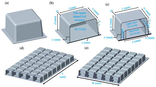
Figure 1.
Schematic design of (a) shared foil resonator unit cell, (b) detailed section view of foil resonator unit cell of single-layer membrane, (c) detailed section view of foil resonator unit cell of double-layer membrane, and (d,e) complete single-layer and double-layer acoustic membranes with section views.
Table 1 presents all of the parameters used in the design of such an acoustic membrane. Three different sizes of foil sound resonators for acoustic membranes have been examined. These are 50 mm × 50 mm, 40 mm × 40 mm, and 30 mm × 30 mm, respectively, with air cavity depths of 15 mm, 20 mm, 25 mm, and 30 mm; foil thicknesses ranging from 0.3 mm to 0.5 mm; and bottom base plate thicknesses ranging from 1.0 mm to 1.5 mm. Similarly, the design of a double-layer acoustic membrane, also based on an elastic foil absorber, is shown in Figure 2. The upper layer has a fixed size of 50 mm × 50 mm and a back cavity depth of 30 mm. In contrast, the inner layer has a fixed size of 40 mm × 40 mm, with varying back cavity depths of 20 mm, 15 mm, and 10 mm, respectively. The complete set of parameters used in the design of the double-layer thin-foil-resonator-based acoustic membrane is provided in Table 2.

Table 1.
Different parameters used to design a thin single-layer foil-resonator-based acoustic membrane.
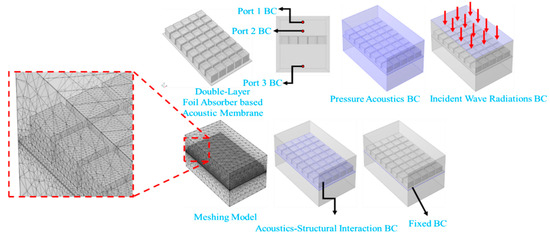
Figure 2.
COMSOL Multiphysics based FEM modeling and boundary conditions.

Table 2.
Different parameters used to design double-layer foil-resonator-based acoustic membrane.
The typical dimensions of the foil coffers are smaller than the wavelengths of the incident sound waves. As a result, the sound disturbance leads to periodic compression of the air inside each coffer, while the various walls of the coffers vibrate in different modes, thereby displacing the volume. In this study, polypropylene (PP) was used as the membrane material, with a mass density of 0.910 g/cm3 and a Young’s modulus of 1300 MPa. The next section, which involves a parametric study, provides a detailed explanation of the selection process for the design parameters and material used for the foil absorber acoustic membrane.
The detailed theoretical formulation of the thin-foil-resonator/absorber-based acoustic membrane has already been described comprehensively in our previous study [50]. According to the law of mass action [52], the sound insulation performance of single-layer and double-layer acoustic membranes can be calculated as follows:
where is the angular velocity, = 343 m/s is the speed of sound in air, and is the air density. represents the mass per unit area, and is the cavity depth between the two surfaces. It has been observed that sound insulation improves to some extent when a double-layer configuration is used instead of a single-layer one. Similarly, it is also evident that an increase in cavity depth between the two layers leads to enhanced sound insulation. The wall thickness of foil resonators is governed by two key factors in the blow molding process: material flow dynamics and stretch deformation during mold filling. This manufacturing technique induces substantial material thinning, with the mold’s geometry producing non-uniform thickness distributions across different regions. Notably, the thickness variations in the top plate, sidewalls, and peripheral edges critically influence both resonant characteristics and acoustic efficiency. Consequently, accurate predictive models for acoustic performance must explicitly account for these process-induced thickness gradients.
In the present work, the foil resonators are made from polypropylene (PP), and the primary loss mechanism we exploit is the radiation damping generated by the enclosed air cavity rather than material (visco-elastic) damping of the thin foil itself. Material damping has been neglected because its contribution is negligible compared to cavity radiation losses.
3. Finite Element Method Simulation
Sound transmission coefficient, reflection coefficient, and absorption coefficient are the primary factors that must be determined to evaluate the sound-insulation performance of acoustic structures and AMs. For complex scenarios, the finite element method (FEM) is a reliable technique for addressing physical problems. The acoustic-structure coupling module in COMSOL Multiphysics 6.2a is employed to compute the STL of the acoustic membrane structure. In this study, PP was used as the acoustic membrane material, with a mass density of 910 kg/m3, Poisson’s ratio of 0.34, and Young’s modulus of 1300 MPa. PP has a high melting point of 200–337 °C and exceptional tensile strength. Our simulations employed the acoustic-structure interaction module to analyze how sound waves interact with the physical structure. This powerful tool, part of the frequency-domain Multiphysics interface, simultaneously calculates both the sound pressure changes in the air and the resulting vibrations in the solid material, capturing their two-way relationship perfectly. For our foil absorber model, we carefully set up different realistic conditions to test its performance, including applying various external forces and sound sources. The simulated sound wave hitting the surface was set at a standard 1 Pascal pressure level, coming straight onto the top face of the membrane. The detailed configuration and formulation used in the FEM-based numerical simulation have been previously described in our earlier study [51]. The mesh independence study has been added (Figure 3) to validate numerical stability. This study confirms that results are mesh-independent, with STL variations ≤ 0.5 dB beyond a threshold mesh quality. The analysis used three mesh sizes for a representative 30 × 30 × 15 mm resonator unit cell (0.3 mm thickness). Table 3 lists all the details related to the mesh element. Finer mesh and extra-fine mesh show almost same behavior, so for this study, we have chosen finer mesh. The added mesh independence study confirms solution convergence and validates the FEM approach. This strengthens confidence in all parametric and experimental comparisons.
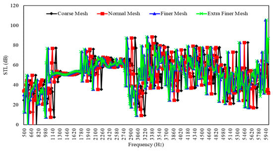
Figure 3.
Mesh independent study.

Table 3.
Different mesh elements and sizes are used for the mesh-independent study.
3.1. Parametric Study Analysis
When conducting an overall performance analysis of a structure, the influence of its parameters cannot be ignored. In this study, a COMSOL Multiphysics FEM simulation-based parametric analysis was performed to comprehensively investigate the effect of each parameter on the overall acoustic performance of the acoustic membrane. To determine the resonance characteristics and acoustic behavior of single-layer and double-layer square wedge-shaped coffer-based acoustic membranes, parameters, such as the thickness of the top surfaces and the depth of the back cavity, play a critical role. This section considers various aspects of thickness and back cavity depth, and their influence on the overall STL performance.
3.1.1. Influence of Back Cavity Depth with Fixed Thickness for Different Sized Foil Resonators
Figure 4 shows the effect of using different back cavity depths while keeping the top surface thickness constant on the overall STL performance of an acoustic membrane based on a thin single-layer square wedge-shaped foil coffer with a size of 30 mm × 30 mm. From the results illustrated in Figure 4a, it is evident that for a thickness of 0.3 mm, as the back cavity depth increases from 15 mm to 30 mm, the frequency peaks shift toward lower frequencies, accompanied by a decline in sound insulation performance, particularly within the frequency range of 1500 Hz to 3600 Hz. When the cavity depth is 15 mm, the single-layer acoustic membrane exhibits an average STL of 51.88 dB within 500 Hz to 3600 Hz, which is the highest among the evaluated cases. A similar trend is observed for a thickness of 0.4 mm in Figure 4b, with an average STL of 53.93 dB at a cavity depth of 20 mm, and for a thickness of 0.5 mm in Figure 4c, where the highest average STL of 58.13 dB is also recorded at a cavity depth of 20 mm.
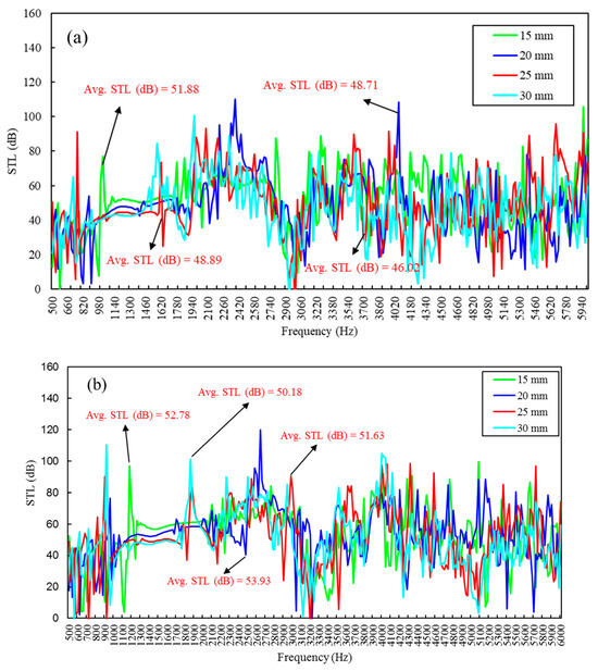
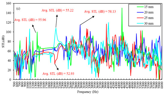
Figure 4.
Effect of back cavity depth on the STL performance of 30 mm × 30 mm size single-layer square wedge-shaped foil-resonator-based acoustic membranes with thicknesses of (a) 0.3 mm, (b) 0.4 mm, and (c) 0.5 mm.
Next, for the single-layer acoustic membrane based on a square wedge-shaped foil coffer with a size of 40 mm × 40 mm, STL performance has been analyzed as shown in Figure 5. As shown in Figure 5a, when the top surface thickness is fixed at 0.3 mm, increasing the back cavity depth from 15 mm to 30 mm causes the frequency peaks to shift lower, with decreasing amplitude observed within the 500 Hz to 2300 Hz range. The maximum average STL of 50.77 dB is recorded at a cavity depth of 25 mm. For a thickness of 0.4 mm, the insulation performance scope extends to 500 Hz to 2950 Hz, with a maximum average STL of 52.88 dB also at 25 mm. For a thickness of 0.5 mm, the frequency band extends up to 3200 Hz, and the maximum average STL of 55.29 dB is achieved at a cavity depth of 20 mm.
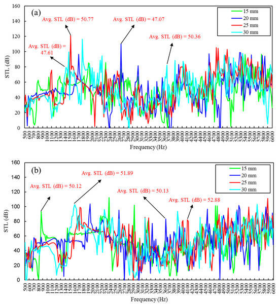
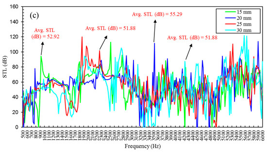
Figure 5.
Effect of back cavity depth on the STL performance of 40 mm × 40 mm size single-layer square wedge-shaped foil-resonator-based acoustic membranes with thicknesses of (a) 0.3 mm, (b) 0.4 mm, and (c) 0.5 mm.
For foil resonators of size 50 mm × 50 mm, the STL performance is illustrated in Figure 5. In Figure 6a, for a thickness of 0.3 mm, a pattern similar to earlier results is observed. With increasing back cavity depth, frequency peaks shift to lower frequencies with a reduction in amplitude within the 950 Hz to 3250 Hz bandwidth. A maximum average STL of 53.4 dB is observed at a cavity depth of 30 mm. Similar behavior is noted for a thickness of 0.4 mm, with a broader bandwidth of 1000 Hz to 3580 Hz and a maximum average STL of 57.60 dB at a cavity depth of 20 mm. For a 0.5 mm thickness, the frequency bandwidth extends from 1350 Hz to 4500 Hz, with a maximum average STL of 53.4 dB at 30 mm cavity depth. Detailed parameters for this study are presented in Table 4.
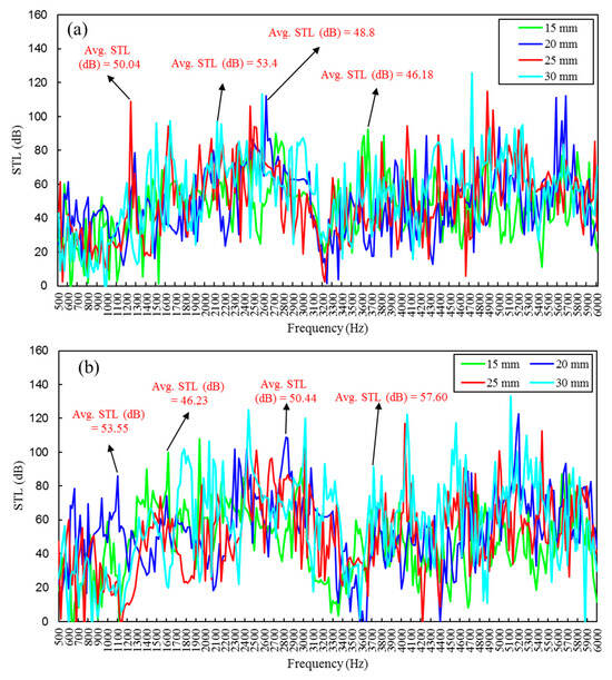
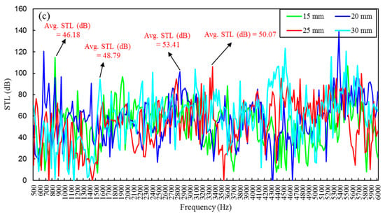
Figure 6.
Effect of back cavity depth on the STL performance of 50 mm × 50 mm size single-layer square wedge-shaped foil-resonator-based acoustic membranes with thicknesses of (a) 0.3 mm, (b) 0.4 mm, and (c) 0.5 mm.

Table 4.
Different parameters used to design a thin single-layer foil-resonator-based acoustic membrane for the influence of back cavity depth with fixed thickness.
Lastly, Figure 7 shows the effect of employing different top surface thicknesses and different inner-layer back cavity depths, while keeping the upper-layer cavity depth fixed at 30 mm, on the overall STL performance of a double-layer foil-resonator-based acoustic membrane. From Figure 7a, it is evident that for an inner-layer cavity depth of 10 mm, as the surface thickness increases from 0.3 mm to 0.5 mm, the frequency peaks shift toward higher frequencies, with improved sound insulation performance. An average STL of 52.84 dB is observed at a surface thickness of 0.5 mm, which is the highest among the tested configurations, especially within the 1000 Hz to 6000 Hz frequency bandwidth. Similar behavior is noted for an inner-layer cavity depth of 15 mm in Figure 7b, where an average STL of 51.04 dB is recorded at 0.3 mm thickness. In Figure 7c, for a back cavity depth of 20 mm, an average STL of 53.41 dB is observed at a thickness of 0.3 mm.
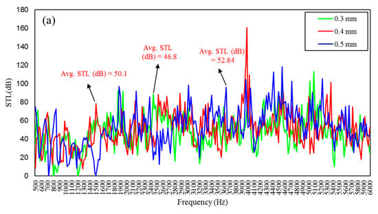
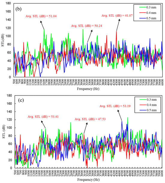
Figure 7.
Effect of top surface thickness and back cavity depth on the STL performance of double-layer foil-resonator-based acoustic membrane with upper layer of size 50 mm × 50 mm with fixed cavity depth of 30 mm and inner-layer of size 40 mm × 40 mm with cavity depths of (a) 10 mm, (b) 15 mm, and (c) 20 mm.
3.1.2. Influence of Fixed Thickness and Back Cavity Depth for Different-Sized Foil Resonators
In the previous section, the importance of the foil thickness in thin-foil-resonator-coffer-based acoustic membranes was demonstrated in relation to overall sound insulation performance. In this section, the influence of different sizes of thin square wedge-shaped foil coffer-based single-layer and double-layer acoustic membranes is examined. Figure 8 illustrates the effect of fixed back cavity depth and fixed thickness on the STL performance for different sizes of thin-foil-resonator coffers. From the results shown in Figure 8a, it can be observed that, with the thickness fixed at 0.3 mm and the cavity depth at 15 mm, increasing the size of the thin-foil-resonator coffer results in higher amplitude frequency peaks, particularly within the range of 1000 Hz to 3350 Hz. A maximum overall average STL of 51.88 dB is achieved for the 50 mm × 50 mm configuration. A similar trend is observed for a cavity depth of 20 mm, where the frequency peaks shift toward the lower-frequency range (750 Hz to 3200 Hz), and a maximum average STL of 48.80 dB is obtained for the 50 mm × 50 mm configuration, as illustrated in Figure 8b. For a cavity depth of 25 mm, the frequency band shifts to 600 Hz to 2950 Hz, and a maximum average STL of 50.77 dB is recorded for the 40 mm × 40 mm configuration. Finally, for a cavity depth of 30 mm, the performance spans 1000 Hz to 6000 Hz, with a maximum average STL of 53.41 dB being achieved.
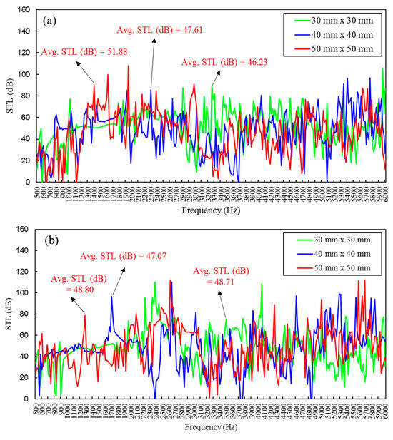
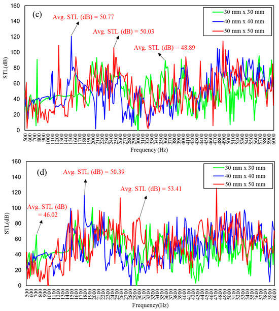
Figure 8.
Effect of 0.3 mm thickness on the STL performance for single-layer square wedge-shaped foil-resonator-based acoustic membranes with a cavity depth of (a) 15 mm, (b) 20 mm, (c) 25 mm, and (d) 30 mm.
Next, the influence of a fixed thickness of 0.4 mm and varying back cavity depths on sound insulation performance is evaluated, as illustrated in Figure 9. When the cavity depth is fixed at 15 mm, increasing the size of the thin-foil-resonator coffer causes the frequency peaks to shift toward lower frequencies with decreasing amplitude. Despite this, the insulation performance improves, attaining effective STL within the range of 1000 Hz to 3300 Hz, with a maximum average STL of 52.78 dB for the 30 mm × 30 mm configuration. Similarly, when the back cavity depth is increased to 20 mm, increasing the resonator size results in further leftward frequency peak shifts and a broader bandwidth ranging from 700 Hz to 3200 Hz, with a maximum average STL of 53.93 dB for the 30 mm × 30 mm configuration, as shown in Figure 9b. For a 25 mm cavity depth, the effective band spans 500 Hz to 2900 Hz, and a maximum average STL of 52.88 dB is achieved for the 40 mm × 40 mm configuration, as shown in Figure 9c. Finally, at a cavity depth of 30 mm, the STL performance spans 500 Hz to 3580 Hz, with a maximum average STL of 57.60 dB attained for the 50 mm × 50 mm configuration, as shown in Figure 9d.
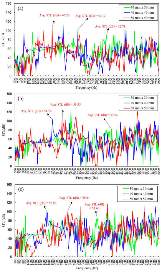
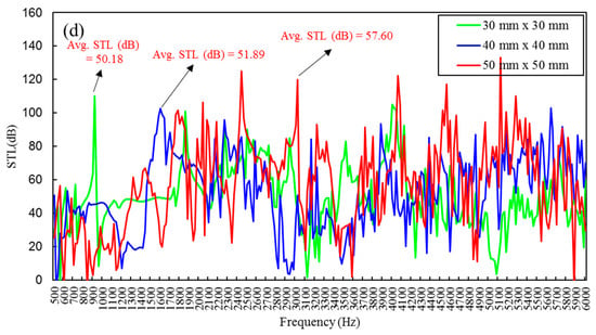
Figure 9.
Effect of 0.4 mm thickness on the STL performance for single-layer square wedge-shaped foil-resonator-based acoustic membranes with a cavity depth of (a) 15 mm, (b) 20 mm, (c) 25 mm, and (d) 30 mm.
Lastly, the influence of a fixed thickness of 0.5 mm and varying back cavity depths on overall sound insulation performance has been investigated, as illustrated in Figure 10. From the results shown in Figure 10a, it can be observed that when the cavity depth is 15 mm, increasing the size of the foil resonator coffer-based acoustic membrane exhibits the same behavior noted in earlier cases. The frequency peaks shift toward lower frequencies, and their amplitudes decrease. For the 30 mm × 30 mm configuration, a maximum overall average STL of 55.96 dB is attained within the 1300 Hz to 6000 Hz frequency range. Similarly, for a cavity depth of 20 mm, the frequency peaks shift further toward lower frequencies, covering the range of 700 Hz to 6000 Hz, with a maximum overall average STL of 58.13 dB observed for the 30 mm × 30 mm configuration, as shown in Figure 10b. For a cavity depth of 25 mm, the STL performance spans 500 Hz to 4950 Hz, with a maximum overall average STL of 54.32 dB for the 40 mm × 40 mm configuration, as shown in Figure 10c. Finally, for a cavity depth of 30 mm, the STL band spans 1350 Hz to 6000 Hz, and the maximum overall average STL of 59.32 dB is achieved, as illustrated in Figure 10d.
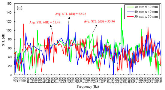
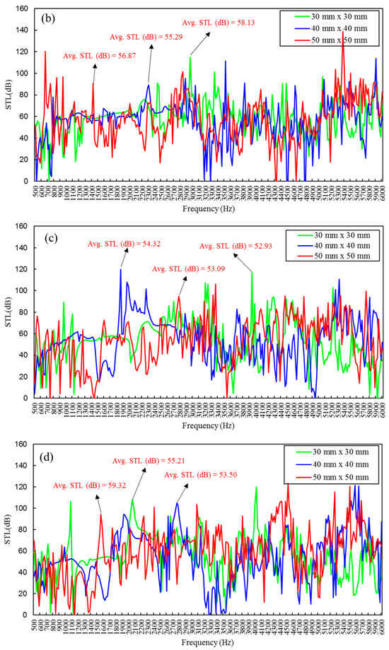
Figure 10.
Effect of 0.5 mm thickness on the STL performance for single-layer square wedge-shaped foil-resonator-based acoustic membranes with a cavity depth of (a) 15 mm, (b) 20 mm, (c) 25 mm, and (d) 30 mm.
Overall, from this parametric study analysis, it has been determined that both top surface thickness and back cavity depth are critical to conducting a comprehensive evaluation. As the top surface thickness increases, the acoustic membranes demonstrate enhanced sound insulation performance, particularly within medium- to higher-frequency ranges. Conversely, increasing the back cavity depth causes the frequency peaks to shift toward lower frequencies. Additionally, the structural configuration, material combinations, individual layer thicknesses, and the frequency and intensity of the incident sound waves all influence the overall sound insulation performance. The detailed parameters used in this parametric study are provided in Table 5.

Table 5.
Different parameters used to design a thin single-layer foil-resonator-based acoustic membrane for the influence of fixed thickness and back cavity depth.
4. Experimental Validation
4.1. Sample Fabrication
The process of extrusion blow molding technology [53] was used to fabricate the acoustic membrane samples. These samples were manufactured using PP material, which has a mass density of 910 kg/m3 and a Young’s modulus of 1300 MPa, as illustrated in Figure 11. Polypropylene (PP) offers several advantages over alternative materials like polyethene terephthalate (PET), polyvinyl chloride (PVC), and nylon. Not only is it more cost-effective, but it also has a melting point ranging from 200 to 337 °C and an impressive tensile strength between 25 and 40 MPa. These properties make PP an ideal choice for this research. Extrusion blow molding involves melting the material, which is then continuously extruded through a molding nozzle to form a tubular shape. This tube is subsequently shaped and cooled within the desired mold geometry. Five different acoustic membrane samples were fabricated based on the findings from the FEM simulation-based parametric study. The complete details of the prepared samples are provided in Table 6.
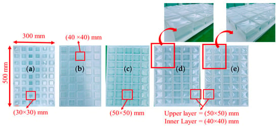
Figure 11.
Extrusion-blow-molding-technology-based final manufactured samples of acoustic membranes with resonator sizes of (a) M1, (b) M2, (c) M3, (d) M4, and (e) M5, respectively.

Table 6.
Different parameters used to prepare the blow-molding-technology-based samples of single-layer and double-layer square wedge-shaped foil-coffer-based acoustic membrane structures.
4.2. Experimental Setup
Experimental validation of the numerical study was conducted in a soundproof anechoic chamber using five microphones positioned at a distance of one meter from the acoustic membrane, and a compressed air pump serving as the sound source. Two types of material enclosures, namely, plastic (acrylic) and steel, were employed, with the acoustic membrane attached to the side and top faces of each box. The compressed air pump was placed in the center of the box above a PU foam layer, which absorbs vibrations during operation, as shown in Figure 12 and Figure 13. The sound source inside the box emits a precisely controlled sound signal with a frequency range up to 10 kHz.
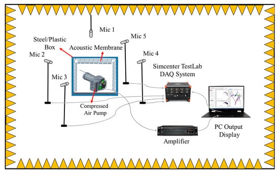
Figure 12.
Schematic of the experimental setup to measure STL inside an anechoic chamber room. Five microphones are located 1 m from the acoustic membrane, which is lined inside the plastic/steel box, and from a sound source.
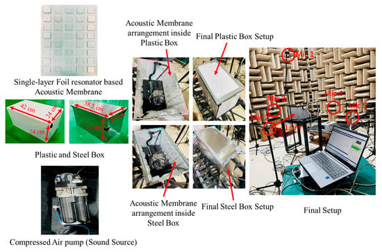
Figure 13.
Experimental setup inside an anechoic chamber.
To ensure accurate measurement results, the edges of each box were carefully sealed to prevent sound leakage. If any gaps are present, sound can bypass the membrane sample, leading to incorrect measurements. In a perfectly diffuse sound field, sound level measurements would be uniform regardless of the microphone’s position within the room. Each sample was tested three times, and the average STL values from all of the microphones were calculated. The use of two different enclosure materials allows for a comparative analysis of the acoustic membrane’s sound insulation performance with and without the presence of additional structural materials. This comparative approach is particularly useful when targeting specific frequency ranges and may enhance noise control performance in domestic, commercial, and industrial applications.
4.3. Results and Discussions
Figure 14 shows how well our single-layer acoustic membrane performed in validation tests. This uniform thin-foil resonator design demonstrated excellent results that confirmed our theoretical predictions. The FEM simulation and experimental results exhibit good agreement, with only minor deviations. For the single-layer uniform thin-foil-resonator-based acoustic membrane sample M1, as illustrated in Figure 14a, the experimental results yield an average STL of 50.27 dB compared to 49.12 dB from the FEM simulation, with the presence of some sharp peaks. For sample M2, the average STL from experiments is 48.96 dB, compared to 46.16 dB from FEM simulation, as shown in Figure 14b, indicating close correlation. Similarly, for sample M3, an experimental average STL of 51.08 dB has been recorded, compared to 49.52 dB from the FEM simulation, as illustrated in Figure 14c, again showing reasonable alignment. Overall, the validation study reveals that sample M3 demonstrates the best STL performance among the three samples, although M1 and M2 also perform comparably well.
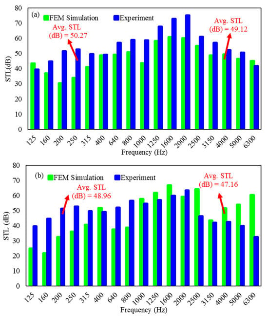
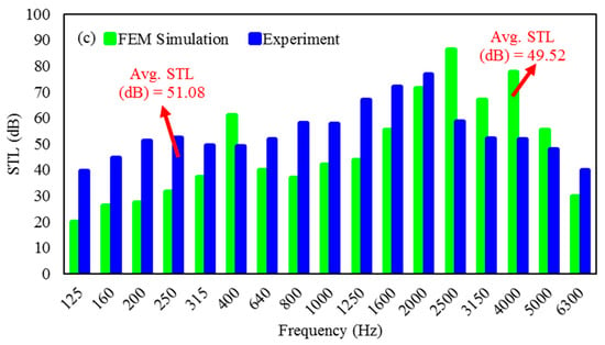
Figure 14.
Experimental vs. simulated STL performance of three different square wedge-shaped foil-resonator acoustic membranes: (a) M1, (b) M2, and (c) M3, showing close agreement between experimental results and FEM predictions.
Next, Figure 15 shows the experimental validation of the double-layer uniform thin-foil-resonator-based acoustic membranes. For sample M4, as shown in Figure 15a, the experimental average STL is 48.11 dB, compared to 46.80 dB from FEM simulation. Likewise, for sample M5 in Figure 15b, the experimental average STL is 47.76 dB, compared to 46.10 dB from the FEM simulation. Across all of the samples, an average STL range of 48 dB to 54 dB has been achieved within the frequency range of 1000 to 6000 Hz using single-layer and double-layer acoustic membranes based on thin-foil resonators. The parameters of resonator size, back cavity depth, and foil thickness significantly influence STL performance and must be optimized to target a specific frequency range. For smaller foil resonators, increasing the back cavity or wall depth enhances acoustic performance. However, for larger resonators, increased cavity or wall height leads to diminished acoustic performance. Therefore, careful consideration must be given to the desired frequency region during the design phase. The minor discrepancies observed between FEM simulation results and experimental peaks may be attributed to oscillations in the thin-walled structure, which can lead to instability in the sound field within the cavity. Minor measurement inconsistencies might occur due to acoustic leakage at frame joints, as well as wave interactions with the membrane perimeter and adhesive tape.
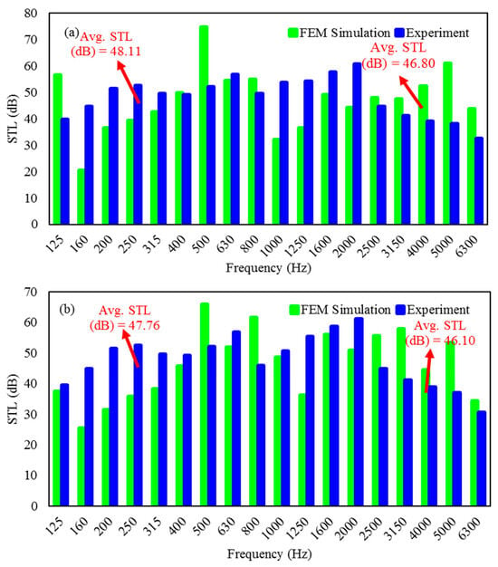
Figure 15.
Experimental vs. simulated STL performance of three different square wedge-shaped foil-resonator acoustic membranes: (a) M4 and (b) M5, showing close agreement between experimental results and FEM predictions.
When analyzing noise and vibration in modern appliances, 1/3 octave band analysis proves particularly valuable for quieting everyday devices, from office equipment to household essentials like air conditioners and washing machines. These sound measurements, recorded in decibels (dB), use a logarithmic frequency scale to better represent how we actually perceive noise. Since human hearing responds differently to various frequencies, researchers apply special weighting adjustments to the data. For this study, we captured precise acoustic measurements using Simcenter Testlab SCADA (version 2306) [54], with the detailed findings illustrated in Figure 14, Figure 15, Figure 16 and Figure 17. A sound source (compressed air pump) was used with a reference sound level OA of 63.51 dB (A), and the performance of various acoustic membranes installed inside plastic and steel boxes was compared against this baseline. As depicted in Figure 16, the noise level (OA) experienced a significant reduction. Specifically, the plastic box by itself achieved a noise reduction of 18.2 dB (A). When combined with a single-layer acoustic membrane, the noise level dropped even further to 20.21 dB (A). The most effective configuration, however, was the plastic box paired with an acoustic membrane, which resulted in a noise reduction of 20.82 dB (A) for the combination with a double-layer foil-resonator-based acoustic membrane within the 500 Hz to 10 kHz frequency band. This confirms that combining a plastic box with a single-layer or double-layer foil resonator-based acoustic membrane can further reduce the sound level (OA) by approximately 2 dB and 3 dB, respectively, compared to using the plastic box alone.
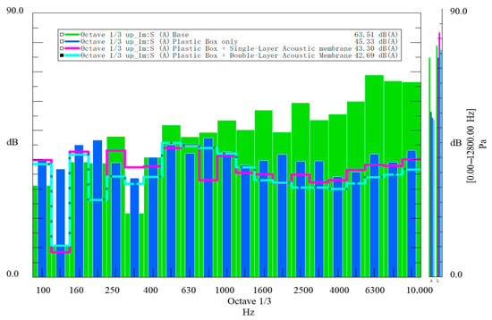
Figure 16.
Measured 1/3 octave and noise levels (OA) comparing: (1) plastic box with single-layer acoustic membrane, (2) double-layer acoustic membrane, and (3) baseline noise source (Base).
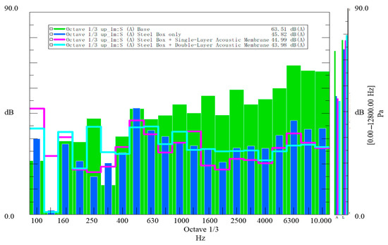
Figure 17.
Measured 1/3 octave and noise levels (OA) comparing: (1) steel box with single-layer acoustic membrane, (2) double-layer acoustic membrane, and (3) baseline noise source (Base).
From Figure 17, it is observed that in the 500 Hz to 10,000 Hz frequency band, the noise level (OA) was reduced by 17.7 dB (A) when using only a steel box. This reduction improved to 18.52 dB (A) with the addition of a single-layer foil resonator-based acoustic membrane and further to 19.53 dB (A) with a double-layer membrane. These results demonstrate that, compared to using a steel box alone, combining it with single-layer and double-layer foil-resonator-based acoustic membranes can achieve an additional sound level reduction of approximately 2 dB and 3 dB, respectively.
Furthermore, the noise level (OA) performance of single-layer foil-resonator-based acoustic membranes was compared when installed in plastic and steel boxes. As depicted in Figure 18, within the 500 Hz to 10 kHz frequency band, the combination of a steel box with a single-layer acoustic membrane achieved a reduction of 18.52 dB (A), whereas the plastic box combined with the same membrane achieved a greater reduction of 20.21 dB (A). This indicates that the plastic box configuration offers an additional 2 dB reduction in sound level (OA) compared to the steel box configuration using the same acoustic membrane.
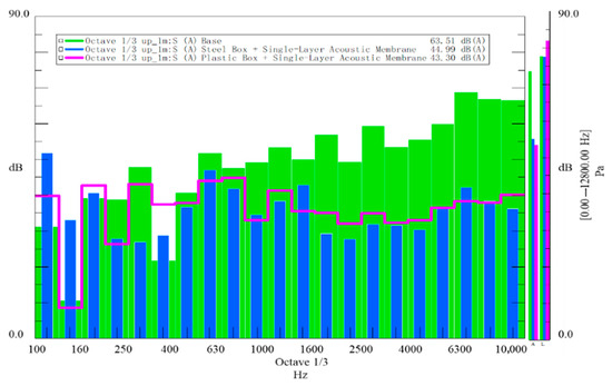
Figure 18.
Comparison of acoustic performance between (1) plastic box with single-layer acoustic membrane, (2) steel box with single-layer acoustic membrane, and (3) baseline noise source (Base), showing 1/3 octave band noise reduction.
Lastly, the noise level (OA) performance of using a double-layer foil-resonator-based acoustic membrane combined with plastic and steel boxes was compared. Figure 19 illustrates that the noise level (OA) was reduced by 19.62 dB (A) for the combination of the steel box with the double-layer foil-resonator-based acoustic membrane, and by 20.68 dB (A) for the combination of the plastic box with the same membrane, within the 500 Hz to 10,000 Hz frequency band. This confirms that the combination of a plastic box with a double-layer foil-resonator-based acoustic membrane can further reduce the sound level (OA) by approximately 1 dB compared to the corresponding steel box configuration.
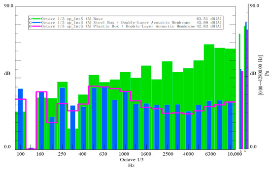
Figure 19.
Comparison of acoustic performance between (1) plastic box with double-layer acoustic membrane, (2) steel box with double-layer acoustic membrane, and (3) baseline noise source (Base), showing 1/3 octave band noise reduction.
From this study, it is evident that combining a plastic box with a double-layer foil-resonator-based acoustic membrane can reduce the overall sound level (OA) by an additional 2–3 dB compared to the use of steel boxes with either single-layer or double-layer foil resonator-based membranes. Both single-layer and double-layer thin-foil-resonator-based acoustic membranes are effective in reducing noise and providing good STL performance. However, the selection between the two configurations depends on the specific application and desired acoustic performance. Single-layer thin-foil-resonator-based acoustic membranes are generally simpler and more cost-effective to manufacture, and they provide satisfactory attenuation of low-frequency noise. However, they may be less effective at mitigating high-frequency noise. In contrast, double-layer thin-foil-resonator-based acoustic membranes offer improved attenuation across low-mid to mid-high frequency ranges and can be engineered to target specific frequency response characteristics, although they may involve increased manufacturing complexity and cost. The sound insulation capacity of a material is governed by its ability to absorb and dampen sound waves. Plastic, being more flexible and lower in density, is less prone to resonance or vibration in response to incident sound waves, which may enhance its sound insulation performance. Furthermore, the method of material combination, the thickness of each individual layer, as well as the frequency and intensity of the sound waves, all contribute significantly to the overall effectiveness of the sound insulation system.
Afterwards, Simcenter Testlab Acquisition software (version 2306) [54] was used to present a dataset in correlation with a third parameter through a colormap display. Figure 20a–d show the relationship between sound pressure (Pa, dB) and frequency (Hz) in terms of peak amplitude for various combinations of plastic and steel boxes with single-layer and double-layer foil-resonator-based acoustic membranes. The colormap display offers a clear visualization of peak pressure distribution across the frequency spectrum during noise and vibration analysis, with distinct peak regions readily observed. The peaks gradually rise and fall along the frequency axis, indicating improved STL within the 630 Hz to 6300 Hz frequency span, corresponding to the best sound insulation performance. These results further validate the effectiveness of the designed acoustic membrane structures.
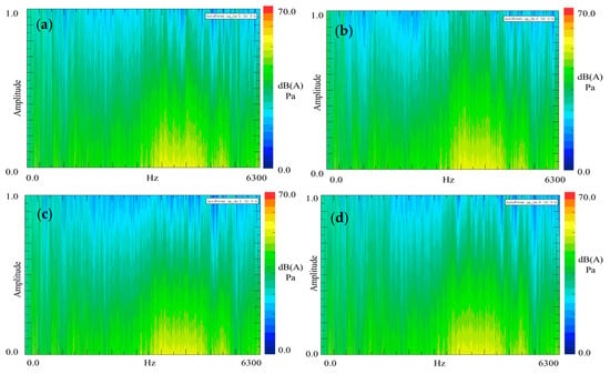
Figure 20.
Sound pressure level (dB) distributions shown in Simcenter Testlab colormaps for four different acoustic membrane configurations: (a) a plastic box with a single-layer acoustic membrane, (b) a steel box with a single-layer acoustic membrane, (c) a plastic box with a double-layer acoustic membrane, and (d) a steel box with a double-layer acoustic membrane. The color gradients reveal distinct noise reduction patterns for each design.
Table 7 compares the STL (dB) of the double-layer acoustic membrane with other samples and materials. Since the surface area of the tested samples and materials varies, the arrangement area of each acoustic structure influences its total sound attenuation capability. To fairly evaluate sound attenuation performance, the average STL (dB) per unit area was calculated by dividing the STL value by the corresponding surface area. Compared to other samples, the double-layer acoustic membrane, with its optimized structural thickness, demonstrates substantial sound attenuation capability. In conclusion, the proposed double-layer acoustic membrane offers significant advantages in enhancing sound insulation performance, whether used independently or in combination with other structural materials.

Table 7.
The comparison of STL between double-layer acoustic membrane with other samples and materials.
5. Conclusions
Based on the numerical and experimental investigations presented in this study, single-layer and double-layer foil-resonator-based acoustic membranes—comprising thin square wedge-shaped foil resonator coffers, back cavity depth, and a thin bottom plate—have been analyzed. Owing to their excellent sound insulation properties, these membranes achieve effective noise reduction over a broad frequency range. The following conclusions can be drawn:
- Due to their simple design and lightweight construction, the developed single-layer and double-layer acoustic membranes based on thin-foil resonators exhibit superior sound insulation performance compared to traditional sound insulation structures.
- A parametric study was conducted by varying the wall thickness and cavity depth to evaluate the impact of each parameter on the membrane’s STL performance. STL improvement across a broader frequency width can be achieved by reducing the wall thickness and size of the foil resonator coffers while increasing cavity depth. Conversely, increasing the thickness and size of the coffers with a smaller back cavity enhances STL performance within a high-frequency width.
- Both single-layer and double-layer thin-foil-resonator-based acoustic membranes are effective in noise attenuation; however, the double-layer membrane is generally more effective. This is attributed to its additional mass, increased stiffness, and the presence of multiple resonant frequencies, which provide improved noise attenuation over a wider frequency range.
- By carefully selecting parameter combinations for single-layer and double-layer square wedge-shaped foil resonator coffer-based acoustic membranes, an average STL of 40 dB to 55 dB can be achieved within the frequency range of 750 Hz to 6000 Hz.
- Experimental testing using combinations of plastic and steel boxes with acoustic membranes inside an anechoic chamber demonstrated a 2–3 dB reduction in overall noise level (OA).
- The current single-layer and double-layer foil-resonator-based acoustic membrane designs offer a promising direction for achieving effective STL performance due to their lightweight structure, water resistance, ease of fabrication, and cost-effectiveness—highlighting their strong potential for noise control applications.
Author Contributions
C.G.: Methodology, Data Curation, Software, Resources, Writing—original draft. F.R.: Conceptualization, Investigation, Validation, Software, and Writing—review and editing. F.Y.: Supervision. All authors have read and agreed to the published version of the manuscript.
Funding
This research received no external funding.
Data Availability Statement
The data presented in this study are available on request from the corresponding authors. The data are not publicly available due to privacy restrictions.
Conflicts of Interest
The authors declare no conflict of interest.
Correction Statement
This article has been republished with a minor correction to the Data Availability Statement. This change does not affect the scientific content of the article.
References
- Commission of the European Communities. Green Paper on: “Future Noise Policy”; Commission of the European Communities: Brussels, Belgium, 1996. [Google Scholar]
- WHO. Burden of Disease from Environmental Noise Burden of Disease from Environmental Noise; World Health Organization: Geneva, Switzerland, 2011. [Google Scholar]
- Rossi, L.; Prato, A.; Lesina, L.; Schiavi, A. Effects of low-frequency noise on human cognitive performances in laboratory. Build. Acoust. 2018, 25, 17–33. [Google Scholar] [CrossRef]
- Song, Y.; Yang, H.; Zhu, N.; Chen, J. Experimental Investigation on the Acoustic Insulation Properties of Filled Paper Honeycomb-Core Wallboards. Biomimetics 2024, 9, 528. [Google Scholar] [CrossRef]
- Takahashi, D.; Sawaki, S.; Mu, R.-L. Improvement of sound insulation performance of double-glazed windows by using viscoelastic connectors. J. Sound Vib. 2016, 371, 56–66. [Google Scholar] [CrossRef]
- Toyoda, M.; Takahashi, D. Sound transmission through a microperforated-panel structure with subdivided air cavities. J. Acoust. Soc. Am. 2008, 124, 3594–3603. [Google Scholar] [CrossRef]
- Liu, Y.; Jacobsen, F. Measurement of absorption with a p-u sound intensity probe in an impedance tube. J. Acoust. Soc. Am. 2005, 118, 2117–2120. [Google Scholar] [CrossRef]
- Hung, T.-C.; Huang, J.-S.; Wang, Y.-W.; Lin, K.-Y. Inorganic polymeric foam as a sound absorbing and insulating material. Constr. Build. Mater. 2014, 50, 328–334. [Google Scholar] [CrossRef]
- Arenas, J.P.; Crocker, M.J. Recent Trends in Porous Sound-Absorbing Materials. Sound Vib. 2010, 44, 11–17. [Google Scholar]
- Dupont, T.; Leclaire, P.; Sicot, O.; Gong, X.L.; Panneton, R. Acoustic properties of air-saturated porous materials containing dead-end porosity. J. Appl. Phys. 2011, 110, 094903. [Google Scholar] [CrossRef]
- Li, H.; Ren, X.; Yu, C.; Xiong, J.; Wang, X.; Zhao, J. Investigation of vibro-acoustic characteristics of FRP plates with porous foam core. Int. J. Mech. Sci. 2021, 209, 106697. [Google Scholar] [CrossRef]
- Gao, N.; Tang, L.; Deng, J.; Lu, K.; Hou, H.; Chen, K. Design, fabrication and sound absorption test of composite porous metamaterial with embedding I-plates into porous polyurethane sponge. Appl. Acoust. 2021, 175, 107845. [Google Scholar] [CrossRef]
- Maa, D.-Y. Potential of microperforated panel absorber. J. Acoust. Soc. Am. 1998, 104, 2861–2866. [Google Scholar] [CrossRef]
- Wang, C.; Huang, L. On the acoustic properties of parallel arrangement of multiple micro-perforated panel absorbers with different cavity depths. J. Acoust. Soc. Am. 2011, 130, 208–218. [Google Scholar] [CrossRef]
- Fan, J.; Zhang, L.; Wei, S.; Zhang, Z.; Choi, S.-K.; Song, B.; Shi, Y. A review of additive manufacturing of metamaterials and developing trends. Mater. Today 2021, 50, 303–328. [Google Scholar] [CrossRef]
- Sagartzazu, X.; Hervella-Nieto, L.; Pagalday, J.M. Review in sound absorbing materials. Arch. Comput. Methods Eng. 2008, 15, 311–342. [Google Scholar] [CrossRef]
- Jaouen, L.; Renault, A.; Deverge, M. Elastic and damping characterizations of acoustical porous materials: Available experimental methods and applications to a melamine foam. Appl. Acoust. 2008, 69, 1129–1140. [Google Scholar] [CrossRef]
- Chevillotte, F.; Panneton, R. Elastic characterization of closed cell foams from impedance tube absorption tests. J. Acoust. Soc. Am. 2007, 122, 2653–2660. [Google Scholar] [CrossRef] [PubMed]
- Zigoneanu, L.; Popa, B.I.; Cummer, S.A. Three-dimensional broadband omnidirectional acoustic ground cloak. Nat. Mater. 2014, 13, 352–355. [Google Scholar] [CrossRef] [PubMed]
- Kan, W.; Shen, Z. Ultra-transparent media with anisotropic mass density for broadband acoustic invisibility. Appl. Phys. Lett. 2017, 111, 223501. [Google Scholar] [CrossRef]
- Liang, Z.; Li, J. Extreme acoustic metamaterial by coiling up space. Phys. Rev. Lett. 2012, 108, 114301. [Google Scholar] [CrossRef]
- Cai, Z.; Zhao, S.; Huang, Z.; Li, Z.; Su, M.; Zhang, Z.; Zhao, Z.; Hu, X.; Wang, Y.; Song, Y. Bubble Architectures for Locally Resonant Acoustic Metamaterials. Adv. Funct. Mater. 2019, 29, 1906984. [Google Scholar] [CrossRef]
- Su, X.; Norris, A.N.; Cushing, C.W.; Haberman, M.R.; Wilson, P.S. Broadband focusing of underwater sound using a transparent pentamode lens. J. Acoust. Soc. Am. 2017, 141, 4408–4417. [Google Scholar] [CrossRef]
- Zhang, T.C.; Chen, J.H.; Qian, J.; Ge, Y.; Yuan, S.Q.; Sun, H.X.; Liu, X.J. Observation of Ultrabroadband Acoustic Focusing Based on V-Shaped Meta-Atoms. Adv. Mater. Technol. 2020, 5, 1900956. [Google Scholar] [CrossRef]
- Jin, Y.; Bonello, B.; Pan, Y. Acoustic metamaterials with piezoelectric resonant structures. J. Phys. D Appl. Phys. 2014, 47, 245301. [Google Scholar] [CrossRef]
- Ma, G.; Yang, M.; Xiao, S.; Yang, Z.; Sheng, P. Acoustic metasurface with hybrid resonances. Nat. Mater. 2014, 13, 873–878. [Google Scholar] [CrossRef] [PubMed]
- Yang, Z.; Dai, H.M.; Chan, N.H.; Ma, G.C.; Sheng, P. Acoustic metamaterial panels for sound attenuation in the 50–1000 Hz regime. Appl. Phys. Lett. 2010, 96, 2012–2015. [Google Scholar] [CrossRef]
- Wu, X.; Fu, C.; Li, X.; Meng, Y.; Gao, Y.; Tian, J.; Wang, L.; Huang, Y.; Yang, Z.; Wen, W. Low-frequency tunable acoustic absorber based on split tube resonators. Appl. Phys. Lett. 2016, 109, 043501. [Google Scholar] [CrossRef]
- Long, H.; Cheng, Y.; Tao, J.; Liu, X. Perfect absorption of low-frequency sound waves by critically coupled subwavelength resonant system. Appl. Phys. Lett. 2017, 110, 023502. [Google Scholar] [CrossRef]
- Liu, C.R.; Wu, J.H.; Yang, Z.; Ma, F. Ultra-broadband acoustic absorption of a thin microperforated panel metamaterial with multi-order resonance. Compos. Struct. 2020, 246, 112366. [Google Scholar]
- Guo, J.; Zhang, X.; Fang, Y.; Qu, R. An extremely-thin acoustic metasurface for low-frequency sound attenuation with a tunable absorption bandwidth. Int. J. Mech. Sci. 2022, 213, 106872. [Google Scholar] [CrossRef]
- Li, Y.; Assouar, B.M. Acoustic metasurface-based perfect absorber with deep subwavelength thickness. Appl. Phys. Lett. 2016, 108, 063502. [Google Scholar] [CrossRef]
- Cai, X.; Guo, Q.; Hu, G.; Yang, J. Ultrathin low-frequency sound absorbing panels based on coplanar spiral tubes or coplanar Helmholtz resonators. Appl. Phys. Lett. 2014, 105, 121901. [Google Scholar] [CrossRef]
- Liu, X.; Wang, C.; Zhang, Y.; Huang, L. Investigation of broadband sound absorption of smart micro-perforated panel (MPP) absorber. Int. J. Mech. Sci. 2021, 199, 106426. [Google Scholar] [CrossRef]
- Mosa, A.I.; Putra, A.; Ramlan, R.; Prasetiyo, I.; Esraa, A.A. Theoretical model of absorption coefficient of an inhomogeneous MPP absorber with multi-cavity depths. Appl. Acoust. 2019, 146, 409–419. [Google Scholar] [CrossRef]
- Rafique, F.; Wu, J.H.; Naqvi, S.M.A.; Ma, F. Enhanced wideband low-frequency sound absorption of a single-layer multiple parallel-arranged inhomogeneous microperforated panel absorber. Acoust. Aust. 2022, 50, 49–69. [Google Scholar] [CrossRef]
- Rafique, F.; Wu, J.H.; Waqas, M.; Lushuai, X.; Ma, F. A thin double-layer multiple parallel-arranged inhomogeneous microperforated panel absorber for wideband low-frequency sound absorption. J. Braz. Soc. Mech. Sci. Eng. 2022, 44, 31. [Google Scholar] [CrossRef]
- Rafique, F.; Wu, J.H.; Liu, C.R.; Ma, F. Low-Frequency Sound Absorption of an Inhomogeneous Micro-Perforated Panel with J-Shaped Cavities of Different Depths. Acoust. Aust. 2022, 50, 203–214. [Google Scholar] [CrossRef]
- Rafique, F.; Hui Wu, J.; Rui Liu, C.; Ma, F. Transmission Loss analysis of a simple expansion chamber muffler with extended inlet and outlet combined with inhomogeneous micro-perforated panel (iMPP). Appl. Acoust. 2022, 194, 108808. [Google Scholar] [CrossRef]
- Rafique, F.; Hui Wu, J.; Naqvi, S.M.A.; Waqas, M.; Liu, C.R. Extremely effective broadband low-frequency sound absorption with inhomogeneous micro-perforated panel (iMPP) backed with spider-web designed cavities. Proc. Inst. Mech. Eng. Part L J. Mater. Des. Appl. 2023, 237, 843–858. [Google Scholar] [CrossRef]
- Krushynska, A.O.; Bosia, F.; Miniaci, M.; Pugno, N.M. Tunable spider-web inspired hybrid labyrinthine acoustic metamaterials for low-frequency sound control. arXiv 2017, arXiv:1701.07622. [Google Scholar]
- Frenzel, T.; David Brehm, J.; Bückmann, T.; Schittny, R.; Kadic, M.; Wegener, M. Three-dimensional labyrinthine acoustic metamaterials. Appl. Phys. Lett. 2013, 103, 061907. [Google Scholar] [CrossRef]
- Xie, Y.; Konneker, A.; Popa, B.I.; Cummer, S.A. Tapered labyrinthine acoustic metamaterials for broadband impedance matching. Appl. Phys. Lett. 2013, 103, 201906. [Google Scholar] [CrossRef]
- Yang, Z.; Mei, J.; Yang, M.; Chan, N.H.; Sheng, P. Membrane-type acoustic metamaterial with negative dynamic mass. Phys. Rev. Lett. 2008, 101, 204301. [Google Scholar] [CrossRef] [PubMed]
- Fan, L.; Chen, Z.; Zhang, S.Y.; Ding, J.; Li, X.J.; Zhang, H. An acoustic metamaterial composed of multi-layer membrane-coated perforated plates for low-frequency sound insulation. Appl. Phys. Lett. 2015, 106, 151908. [Google Scholar] [CrossRef]
- Langfeldt, F.; Riecken, J.; Gleine, W.; Von Estorff, O. A membrane-type acoustic metamaterial with adjustable acoustic properties. J. Sound Vib. 2016, 373, 1–18. [Google Scholar] [CrossRef]
- Langfeldt, F.; Gleine, W. Membrane- and plate-type acoustic metamaterials with elastic unit cell edges. J. Sound Vib. 2019, 453, 65–86. [Google Scholar] [CrossRef]
- Ang, L.Y.L.; Koh, Y.K.; Lee, H.P. Broadband sound transmission loss of a large-scale membrane-type acoustic metamaterial for low-frequency noise control. Appl. Phys. Lett. 2017, 111, 041903. [Google Scholar] [CrossRef]
- Fratoni, G.; Tenpierik, M.; Turrin, M.; Garai, M.; D’ORazio, D. Acoustic performance of multi-resonator screens in a virtually reconstructed open-plan office. Appl. Acoust. 2025, 229, 110381. [Google Scholar] [CrossRef]
- Triwulandari, E.; Prihastuti, H.; Haryono, A.; Susilo, E. Synthesis and Structure Properties of Rigid Polyurethane Foam From Palm Oil Based Polyol. Indones. J. Mater. Sci. 2008, 2008, 31–36. [Google Scholar]
- Rafique, F.; Gong, C.; Shigong, S.; Wenbo, L.; Yunzhu, W.; Yang, F.P. Designing and experimental validation of single-layer mixed foil resonator acoustic membrane to enhance sound transmission loss (STL) within low to medium frequency range. Appl. Acoust. 2024, 219, 109930. [Google Scholar] [CrossRef]
- Du, G.; Zhu, Z.; Gong, X. Fundamentals of Acoustics, 3rd ed.; Nanjing University Press: Nanjing, China, 2012. [Google Scholar]
- Kutz, M. Processing, Sustainability, Materials, and Applications. In Applied Plastics Engineering Handbook; Elsevier B.V.: Amsterdam, The Netherlands, 2023; pp. 1–870S. [Google Scholar]
- Siemens Digital Industries Software. Simcenter Testlab (Version 2306). 2023. Available online: https://plm.sw.siemens.com/en-US/simcenter/physical-testing/testlab/ (accessed on 20 January 2024).
- Doutres, O.; Salissou, Y.; Atalla, N.; Panneton, R. Evaluation of the acoustic and non-acoustic properties of sound absorbing materials using a three-microphone impedance tube. Appl. Acoust. 2010, 71, 506–509. [Google Scholar] [CrossRef]
- Lomte, A.; Sharma, B.; Drouin, M.; Schaffarzick, D. Sound absorption and transmission loss properties of open-celled aluminum foams with stepwise relative density gradients. Appl. Acoust. 2022, 193, 108780. [Google Scholar] [CrossRef]
- Zai, B.A.; Sami, S.; Ali, R. Determination of Acoustic Characteristics of Melamine foam with Experimental Validation. J. Appl. Mech. Eng. 2021, 10, 366. [Google Scholar]
Disclaimer/Publisher’s Note: The statements, opinions and data contained in all publications are solely those of the individual author(s) and contributor(s) and not of MDPI and/or the editor(s). MDPI and/or the editor(s) disclaim responsibility for any injury to people or property resulting from any ideas, methods, instructions or products referred to in the content. |
© 2025 by the authors. Licensee MDPI, Basel, Switzerland. This article is an open access article distributed under the terms and conditions of the Creative Commons Attribution (CC BY) license (https://creativecommons.org/licenses/by/4.0/).