Abstract
A single-crystal magnesium oxide (MgO) dual-Fabry–Perot (FP)-cavity sensor based on MEMS technology and laser micromachining is proposed for simultaneous measurement of temperature and pressure. The pressure sensitive cavity is processed by wet chemical etching and direct bonding, which can improve machining efficiency, ensure the quality of the reflection surface and achieve thermal stress matching. Femtosecond laser and micromachining technologies are used to fabricate a rough surface and a through hole to reduce the reflect surface and fix the optical fiber. The bottom surface of the pressure cavity and the upper surface of the MgO wafer form a temperature cavity. A cross-correlation signal demodulation algorithm combined with a temperature decoupling method is proposed to achieve dual-cavity demodulation and eliminate the cross-sensitivity between temperature and pressure, improving the accuracy of pressure measurement. Experimental results show that the proposed sensor can stably operate at an ambient environment of 22–800 °C and 0–0.5 MPa with a pressure sensitivity of approximately 0.20 µm/MPa (room temperature), a repeatability error of 2.06% and a hysteresis error of 1.90%. After temperature compensation, thermal crosstalk is effectively eliminated and the pressure measurement accuracy is 2.01%F.S.
1. Introduction
Pressure and temperature detection in high-temperature environments is required in aerospace, equipment development, petrochemical and other fields. As a key example, with the development of the space industry and the research of new generation engines, in situ pressure and temperature measurement of key parts such as pipes, chambers and combustion chambers plays an important role in engine tests, combustion instability analysis, mode switching of engine systems and so on [1,2,3]. In engineering fields, temperature and pressure are often measured separately, which is not conducive to real-time and in situ information acquisition.
High-temperature pressure sensors are mainly divided into two types: electrical and optical. Among them, electrical measurement methods often use air-cooled or water-cooled methods to improve the operating temperature of the sensor, which increases the complexity of the sensing system [4,5]. Meanwhile, the problem of heat conduction damage to the subsequent electronic circuit also limits the application of the sensor [6,7]. Fiber-optic Fabry–Perot (FP) sensors have the advantages of small size, long transmission distance and immunity to electromagnetic interference; however, the operating temperature is limited by the sensor composition material, signal transmission mode and demodulation method. In order to achieve high-temperature applications of the sensor, many studies have been carried out on sensitive units composed of high-temperature resistant materials such as quartz [8], silicon [9], silicon carbide [10], and sapphire [11,12]. Meanwhile, MEMS (Micro-Electro-Mechanical System) and laser processing methods have great advantages in sensor consistency and thermal stress matching manufacturing [13,14,15,16]. Liang et al. [17] proposed a SiC pressure sensor, which can work stably at 400 °C. Li et al. [18] processed an all-silica optical fiber pressure sensor by direct bonding and laser welding technology, but the operating temperature was only 800 °C because of the softening of the silica at high temperature. To improve the operating temperature of the sensor, single-crystal oxide materials, such as sapphire (α-Al2O3), magnesium oxide (MgO) and so on, have attracted extensive attention as ideal materials for the construction of sensors because of their high melting point and good optical properties. Meanwhile, replacing silica fiber with sapphire fiber can overcome the limitation of sensor operating temperature imposed by the melting point of optical fiber. Zhang et al. [19,20] increased the working temperature from 1000 °C to 1400 °C by optimizing the structure and processing method of the sapphire sensor. Shao et al. [21] fabricated a high-sensitivity optical fiber Fabry–Perot sensor based on an all-sapphire structure, which can work stably up to 1200 °C with a high sensitivity of 1.193 µm/mPa. However, at present, the detection results of most high-temperature pressure sensors are affected by ultra-high temperatures. Therefore, it is very necessary to eliminate the influence of temperature on the pressure detection results.
To achieve temperature compensation, dual-parameter sensors based on fiber Bragg grating (FBG) [22,23] or optical composite FP cavities are proposed for temperature detection and to provide real-time temperature information. But the strain–temperature cross-sensitivity problem of FBG is an important factor affecting the accuracy of temperature decoupling. Chen and Yin et al. [24,25] fabricated pressure/temperature optical fiber FP sensors based on MEMS. However, due to the limitations of the constituent materials and structure of the sensor, the operating temperature is relatively low. Jiang et al. fabricated sapphire dual FP cavities for temperature and pressure measurements, respectively. However, the problems of heterogeneous optical fiber welding and mode transmission within sapphire optical fiber remain important factors restricting the yield and performance of sensors. With a high melting point of over 2800 °C, MgO has the potential to be used as a constituent material for higher temperature sensors [26]. A MgO MEMS-based fiber-optic Fabry–Perot pressure sensor has been studied at 800 °C in our previous work [27]. However, the problem of temperature and pressure crosstalk remains an important factor affecting the performance of the sensor.
In this paper, we further propose a MgO dual-FP-cavity optical fiber temperature and pressure sensor (MFPTP) for complex thermo-mechanical coupled environment applications. The sensitive head of MFPTP is prepared by MEMS and laser process technologies. A vacuum cavity and a MgO backplane cavity formed by wet etching and direct bonding were used for pressure and temperature measurement, respectively. A cross-correlation demodulation algorithm is adopted to separate the dual-FP-cavity length information. Then, the temperature decoupling method is used to correct the sensitivity and other information of the sensor. Experimental results show that the sensor can operate normally at 800 °C, which provides an effective approach for mechanical parameter testing technology in harsh environments.
2. Structure and Principle
The schematic diagram of MFPTP is shown in Figure 1a. The sensor head adopts a three-layer MgO structure, including a holder layer with a through hole, a backplane layer and a sensitive diaphragm layer. The through hole is used for fixing the gold-plated multimode optical fiber (MMF, AFIBER Photonics Co., Ltd., Ningbo, China). An all-silica microsphere lens was designed and fabricated at the end face of MMF to improve the coupling efficiency of free-space light. The light injects into the MMF and is reflected between surfaces R1, R2, and R3, and then the long cavity, backplane cavity, and vacuum cavity are formed. In addition, to reduce the reflective surface, the outer surface of the MgO pressure-sensitive diaphragm is roughened by a femtosecond laser.
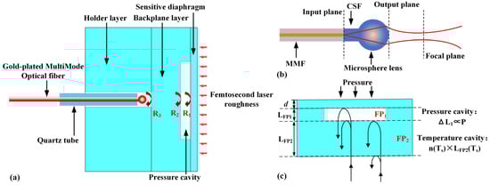
Figure 1.
(a) Schematic diagram of the MFPTP; (b) schematic of beam propagation through a microsphere-lensed fiber; (c) model of dual-FP-cavity deflection for temperature and pressure.
2.1. The Principle of Sensor
As shown in Figure 1b, a microsphere lens on the end face of MMF is studied by laser processing coreless silica fiber (CSF, YOFC, Wuhan, China). Similar to the transmission and divergence of a light beam in a single-mode optical fiber and its propagation on the microsphere lens [28,29], the light is transmitted from the MMF to the CSF and exits the output plane through the microsphere lens. Moreover, the focal plane position is determined by the focal length of the microsphere lens, which is related to the diameter of microsphere lens and the length of the CSF.
When the emitted light from the microsphere lens enters the sensor head, it is reflected on the R1, R2, and R3 surfaces, resulting in multiple interference fringes. The reflection spectrum of the sensor formed by the three reflected beams can be expressed as follows [30]:
where is the light wavelength, , and are the relative intensity of R1, R2 and R3 reflected light beams, , and are the coherence of the interference fringes of pairwise light beams, and are the refractive indices of air and MgO and and are the cavity lengths of the vacuum cavity and backplane cavity, respectively. The is affected by the pressure and temperature, and the is mainly affected by temperature.
From Equation (1), it can be seen that the reflection spectrum of the sensor will change accordingly with and . As shown in Figure 1c, the sensitive diaphragm deformation caused by the external pressure is directly converted into the length change of , which subsequently leads to the phase variation of the reflected light beam. According to the principle of elasticity mechanics, when the pressure is applied, the central deflection of the sensitive diaphragm can be expressed as follows [31]:
where is the applied pressure on the sensitive diaphragm, and are Young’s Modulus and Poisson’s ratio of MgO and and are the effective radius and thickness of the sensitive diaphragm. Hence, the pressure cavity length of FP1 under different pressures can be expressed as follows:
where is the initial cavity length of the pressure cavity. Furthermore, the pressure sensitivity is as follows:
It can be seen from Equations (2) and (4) that increasing the effective radius and reducing the diaphragm thickness can improve the sensitivity of the sensor. However, this will reduce the pressure range of the sensor. Therefore, the range and sensitivity requirements can be met by designing the radius and thickness. The radius of the designed sensor cavity is 1.3 mm and the thickness of the sensitive diaphragm is 200 μm.
When the temperature changes, the coefficient of thermal expansion and the thermally induced refractive index of the MgO also change accordingly. Since the backplane cavity is located in the middle layer of the sensitive unit and is theoretically independent of pressure, it can be used as a temperature cavity. The varies with the temperature and can be expressed as follows:
where is the ambient temperature, is the room temperature, is the initial cavity length of the temperature cavity, and is the coefficient of thermal expansion of MgO at different temperatures.
2.2. Demodulation and Temperature Decoupling Principle
In terms of dual-parameter signal demodulation, the cross-correlation algorithm is adopted to solve the obtained spectral data [32,33,34]. Firstly, a fast Fourier transform (FFT) is performed on the spectral data to obtain the frequency spectrum, which contains multiple cavity lengths. Then, a bandpass filter is used to extract the characteristic frequencies of the pressure and temperature cavities. Finally, after the inverse Fourier transform, the cross-correlation results of L1 and L2 can be obtained.
The temperature changes not only lead to variations in the temperature cavity length but also affect the pressure sensitivity and accuracy. In order to eliminate the crosstalk between temperature and pressure in a high-temperature environment, a temperature compensation method based on the temperature cavity is established. The calibration curve of temperature (T) and temperature cavity length () is obtained through test results to acquire the actual temperature value (). Then, a pressure–temperature compensation matrix is constructed based on the pressure–temperature fitting curves at different temperatures, and the zero drift and pressure sensitivity drift can be compensated. Hence, the actual pressure after temperature compensation is as follows:
where is the FP1 cavity length at different pressures and temperatures, and are the zero drift and sensitivity drift of the sensor.
3. Sensor Fabrication
Double-sided polished MgO wafers were used as the holder layer, backplane layer and sensitive diaphragm layer of the sensor head. The fabrication process mainly included Micro-Electro-Mechanical-System (MEMS) processing of the sensor head, laser processing of the microsphere lens, and optical fiber-sensitive unit integration, as shown in Figure 2.
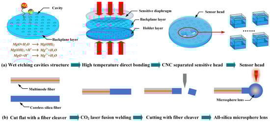
Figure 2.
(a) Schematic diagram of MEMS processing for sensor heads; (b) schematic diagram of the laser processing of the microsphere lens on the end face of the MMF.
As shown in Figure 2a, similar to our previous work [35,36], we employ the wet chemical etching method to fabricate cavity array with the radius of 0.8 mm and depth of 35 μm in a commercially available 2 in. double-side polished MgO{100} wafer with the thickness of 250 μm. A through hole array with a diameter of 1 mm on the holder layer with a thickness of 2 mm machined by using CNC technology is used. Subsequently, surface activation combined with the high-temperature pressure annealing method is used to bond multi-layer MgO wafers, and the cavity array is coaxial with the through hole. The bonding steps and parameters are listed in Table 1. The all-MgO sensor heads were separated from the bonded wafer using laser cutting. Through the above steps, the manufacturing of the sensor head is completed, as shown in Figure 3a. With the MEMS processing method, the thermal stress matching and batch production of the sensor head can be easily realized.

Table 1.
Parameters corresponding to different bonding steps of MgO.
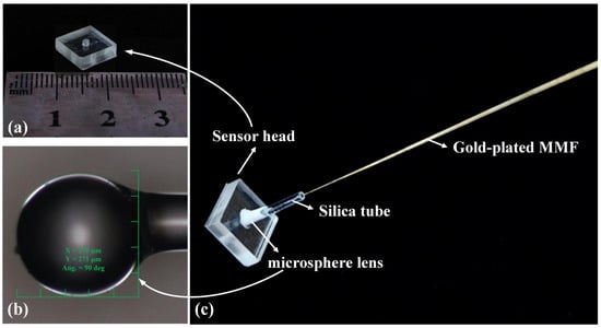
Figure 3.
(a) Schematic diagram of MEMS processing for sensor heads; (b) microscopic image of the microsphere lens at the end face of the MMF; (c) actual image of the sensor.
In order to effectively improve the spectral quality of the sensor at high temperatures, a microsphere lens is designed and fabricated at the end face of MMF [28]. As shown in Figure 2b, the flat end faces of MMF (65/125 μm) and CSF (125/250 μm) were prepared by cleaning and cutting steps. Thereafter, the two fibers are stably welded together using a CO2 laser (LZM-100, Fujikura Ltd., Tokyo, Japan). The CSF is left with a length of 0.9 mm~1 mm after being cut by a fiber cleaver, and the diameter of the microsphere lens is approximately 260 μm in theory. As can be seen from the observation result of optical confocal microscopy in Figure 3b, the diameter of the microsphere is approximately 270 μm, which is basically consistent with the design value. The microspherical lens is inserted into the silica tube, and then the entire structure is inserted vertically into the sensor head. The sensor head and silica tube are then assembled by using high-temperature resistant glue, and then the MFPTP is realized, as shown in Figure 3c.
4. Experiments and Discussion
A temperature and pressure test system is set up to investigate the performance of the sensor under different temperatures and pressures, as shown in Figure 4. The test system consists of a high temperature and pressure testing platform (JT1500, JIANGTAI Co., Ltd., Beijing, China) and a demodulator system. The sensor is inserted into the high-temperature area of high-temperature pressure tank (HPT), and the pressure and temperature are precisely controlled within ±0.1 kPa and ±1 °C by the electrical control system. Meanwhile, a tungsten–rhenium thermocouple and a standard pressure sensor are installed inside the furnace, which as part of the test system, to provide real-time temperature and pressure information. The light emitted by the tungsten-halogen lamp (HL2000-20W, Shanghai Wenyi Optoelectronic Technology Co., Ltd., Shanghai, China) enters the sensor through the optical coupler, and then the MMF is led out from the HPT and connected to the microspectral module (FCV-109, Ibsen Photonics A/S, Farum, Denmark). Then, the spectrum is collected and processed using the cross-correlation demodulation algorithm, and the cavity lengths of the temperature and pressure can be demodulated.
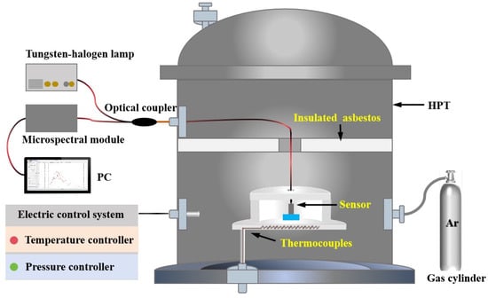
Figure 4.
Experimental set up for measurement of pressure and temperature.
Figure 5a shows the original reflection spectrum of the MFPTP. After FFT, the frequency spectrum is shown in Figure 5b. The first and second peak positions correspond to the frequency of and respectively. Then, an inverse Fourier transform analysis is performed. The and can be calculated when the number of mutual relations is at its maximum. The cross-correlation results of L1 and L2 are shown in Figure 5c,d. The cavity lengths of pressure and temperature are 33.182 μm and 347.394 μm, respectively. Meanwhile, the cavity length values can be displayed on the upper computer display interface directly.
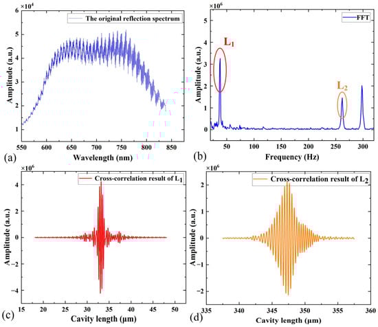
Figure 5.
(a) The original reflection spectrum of the sensor, (b) the frequency spectrum of the sensor, (c) the cross-correlation result of the pressure cavity and (d) the cross-correlation result of the temperature cavity.
During the experiments, the performance of the sensor, including hysteresis, repeatability, and linearity, is tested and characterized at room temperature and high temperatures (up to 800 °C). We altered the pressure from approximately 0 MPa to 0.5 MPa in steps of 0.1 MPa at room temperature (22 °C). The FP cavity length changes during the increase and decrease pressure over three cycles are shown in Figure 6a. It can be seen that the cavity length changes approximately linearly with the pressure increase and decrease during each process. The results show that the sensor has a good repeatability under the same conditions, and the maximum repeatability error is 2.06%. Furthermore, the sensor maintains a good consistency during the loading and unloading pressure stages with a hysteresis error of 1.90%. The sensitivities of three tests are 0.203, 0.203, and 0.206 μm/MPa. Figure 6b shows the pressure cavity length of the sensor with respect to the pressure at temperatures from 22 °C to 800 °C. It can be concluded that the cavity length varies linearly with the pressure at each temperature, and the maximum nonlinearity is 3.16% at 800 °C. The fitted operating straight lines of the sensor at different temperatures are as follows:
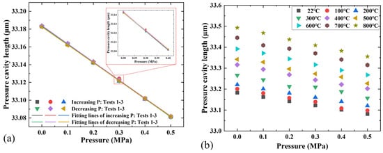
Figure 6.
(a) Pressure cavity length responses of the sensor during three cycles experiments at room temperature and (b) pressure cavity length changes with the pressure under different temperatures.
As can be seen from Figure 7a, the pressure sensitivity progressively increases with the temperature, attaining 0.275 μm/MPa at 800 °C. This phenomenon results from the temperature-dependent variation of the thermal expansion coefficient, Young’s modulus and Poisson’s ratio of MgO. The sensitivity at different temperatures can be expressed as follows:
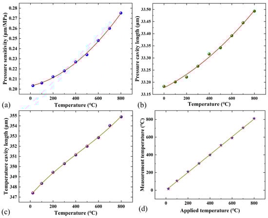
Figure 7.
(a) Pressure sensitivities of sensor in the range from 22 °C to 800 °C, (b) temperature response of pressure cavity, (c) temperature response of temperature cavity and (d) comparison between the applied temperature and the measured temperature.
Therefore, it is necessary to measure the ambient temperature and reduce the influence of the temperature on the pressure measurement. The temperature responses of the pressure cavity and the temperature cavity at 0 MPa are shown in Figure 7b,c. The results show that as the temperature increases, the initial pressure cavity length of the sensor increases slightly, while the temperature cavity length changes significantly. The (T) at different temperatures and the standard equation for the actual temperature measured by this sensor are obtained as follows:
The comparison between the applied temperature and the measurement temperature is shown in Figure 7d. The maximum error is 9.75 °C, and the temperature measurement accuracy is 1.22%F.S. Finally, the deviation results of applied pressure and decoupled pressure values at different temperatures obtained by the temperature decoupling method are shown in Figure 8a. The maximum deviation between the applied and measured pressures was observed at 800 °C and 0.5 MPa, with a value of approximately 10.03 kPa. It can be seen from the coincidence of the curve that the test results of the sensor have been corrected after temperature decoupling. The pressure measurement accuracy is 2.01%F.S. at 800 °C, and the accuracies across the entire temperature range are less than 2.01%F.S. Figure 8b shows the stability test results of the temperature and pressure cavity lengths of the sensor. It can be seen that the maximum fluctuations in pressure and temperature cavity lengths are 30 nm and 29 nm, respectively. This may be caused by the temperature fluctuations and pressure hysteresis.
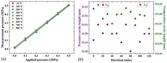
Figure 8.
(a) Temperature decoupling results at different temperatures and (b) the stability results of pressure and temperature cavities of the sensor.
5. Conclusions
In order to achieve dual-parameter measurement of temperature and pressure in high-temperature environments such as engines and to improve the accuracy of pressure detection results, a temperature-compensated fiber-optic Fabry–Perot pressure sensor based on MgO MEMS technology and laser processing method is proposed, designed and demonstrated. This MEMS processing method realizes the batch production and thermal stress matching of the sensor sensitive unit, ensuring the feasibility of the sensor at high temperatures. A microsphere lens was fabricated on the end of MMF to enhance the coupling efficiency of free-space light and effectively improve the spectral quality of the sensor at high temperatures. Meanwhile, the temperature decoupling method was utilized to correct the zero drift and sensitivity drift of the sensor. Over the pressure range of approximately 0 MPa to 0.5 MPa at different temperatures, the pressure FP cavity shows a nearly linear response. The pressure sensitivity increases from 0.203 µm/MPa at room temperature to 0.275 µm/MPa at 800 °C. After temperature compensation, the temperature measurement accuracy is 1.22%F.S, and the pressure measurement accuracy is better than 2.01%F.S. This sensor has the characteristics of high-temperature resistance and a simple structure, and can provide technical support for temperature and pressure measurement in extreme environments.
Author Contributions
Conceptualization, J.L. and P.J.; methodology, J.L. and L.Z.; software, J.L., L.Z. and Y.D.; validation, J.L., L.Z. and Z.W.; data curation, J.L. and R.C.; writing—original draft preparation, J.L.; writing—review and editing, J.L. and P.J.; All authors have read and agreed to the published version of the manuscript.
Funding
This research was funded by the National Key Research and Development Program of China (2023YFB406900).
Institutional Review Board Statement
Not applicable.
Informed Consent Statement
Not applicable.
Data Availability Statement
The data presented in this study are available on request from the corresponding author. The data are not publicly available due to privacy.
Conflicts of Interest
The authors declare no conflicts of interest.
References
- Cao, Y.; Li, G.; Li, Z.; Chen, J.; Zheng, Y.; Zhao, D.; Yang, Y.; Xue, C. Extreme dual-parameter measurement of high static pressure and high acoustic pressure based on fibre-optic Fabry-Pérot sensor at 500 °C. Opt. Laser Technol. 2025, 188, 112955. [Google Scholar] [CrossRef]
- Faure-Beaulieu, A.; Dharmaputra, B.; Schuermans, B.; Wang, G.; Caruso, S.; Zahn, M.; Noiray, N. Measuring acoustic transfer matrices of high-pressure hydrogen/air flames for aircraft propulsion. Combust. Flame 2024, 270, 113776. [Google Scholar] [CrossRef]
- Lee, B.; Kim, C.; Yang, I.; Lee, K.; Lee, Y. Performance Evaluation of a Rake Used for Measuring Total Pressure and Total Temperature Inside an Engine Inlet Duct. Int. J. Aeronaut. Space Sci. 2019, 20, 346–354. [Google Scholar] [CrossRef]
- Zhang, Q.; Ma, H.; Guo, J.; Li, Z.; Xiao, A.; Liu, Y. Analysis of cooling effects and measurement errors in water-cooled thermocouples for total temperature measurement in aviation engine combustion chambers. Int. J. Therm. Sci. 2024, 205, 109290. [Google Scholar] [CrossRef]
- Belavic, D.; Bradesko, A.; Zarnik, M.S.; Rojac, T. Construction of a piezoelectric-based resonance ceramic pressure sensor designed for high-temperature applications. Metrol. Meas. Syst. 2015, 22, 331–340. [Google Scholar] [CrossRef]
- Daniel, J.; Nguyen, S.; Chowdhury, M.A.R.; Xu, S.; Xu, C. Temperature and pressure wireless ceramic sensor (Distance = 0.5 meter) for extreme environment applications. Sensors 2021, 21, 6648. [Google Scholar] [CrossRef]
- Sun, B.; Xiong, J.; Hong, Y.; Zhang, W.; Bi, K.; Zheng, M.; Li, C. AC Bridge Pressure Sensor With Temperature Compensation for High Temperature and Pressure Composite Environment. IEEE Sens. J. 2024, 24, 36579–36586. [Google Scholar] [CrossRef]
- Zhang, W.; Zhang, Z.; Yao, B.; Jing, J.; Xu, Y.; Zhao, Z.; Guo, Y.; Xue, C.; Tian, Z. A Masterpiece of Superior Crystals: Quartz Resonant Pressure Sensor—A Review. IEEE Sens. J. 2024, 24, 9278–9298. [Google Scholar] [CrossRef]
- Yu, H.; Wang, J.; Lu, Y.; Xie, B.; Shang, Y.; Liu, Z. A silicon resonant pressure sensor based on thermal stresses matched structures. J. Phys. Conf. Ser. 2023, 2740, 012041. [Google Scholar] [CrossRef]
- Stefano, S.; Ponticelli, G.S.; Pettinato, S.; Genna, S.; Guarino, S. High-Pressure Sensors Based on Laser-Manufactured Sintered Silicon Carbide. Appl. Sci. 2020, 10, 7095. [Google Scholar]
- Yi, J. Sapphire Fabry-Perot Pressure Sensor at High Temperature. IEEE Sens. J. 2020, 21, 1596–1602. [Google Scholar] [CrossRef]
- Wang, Z.; Chen, J.; Wei, H.; Liu, H.; Ma, Z.; Chen, N.; Chen, Z.; Wang, T.; Pang, F. Sapphire Fabry-Perot interferometer for high-temperature pressure sensing. Appl. Opt. 2020, 59, 5189–5196. [Google Scholar] [CrossRef]
- Yi, J.; Lally, E.; Wang, A.; Xu, Y. Demonstration of an all-sapphire Fabry-Pérot cavity for pressure sensing. IEEE Photonics Technol. Lett. 2010, 23, 9–11. [Google Scholar] [CrossRef]
- Lazic, A.; Smiljanic, M.M.; Tanaskovic, D.; Raljic-Rafajilovic, M.; Cvetanovic, K.; Milinkovic, E.; Bokovic, M.V.; Andric, S.; Jokic, I.; Poljak, P.; et al. Novel MEMS Multisensor Chip for Aerodynamic Pressure Measurements. Sensors 2025, 25, 600. [Google Scholar] [CrossRef]
- Li, T.; Huang, T.; Zheng, Y.; Wang, N.; Han, X.; Tan, Y.; Zhou, Z. High Temperature-Pressure Metalized Optical Fiber Dual FP Sensor with Welding Encapsulation. IEEE Sens. J. 2024, 24, 25724–25733. [Google Scholar] [CrossRef]
- Qi, X.; Wang, S.; Jiang, J.; Liu, K.; Wang, X.; Yang, Y.; Liu, T. Fiber Optic Fabry-Perot Pressure Sensor with Embedded MEMS Micro-Cavity for Ultra-High Pressure Detection. J. Light. Technol. 2018, 37, 2719–2725. [Google Scholar] [CrossRef]
- Liang, T.; Li, W.; Lei, C.; Li, Y.; Li, Z.; Xiong, J. All-SiC Fiber-Optic Sensor Based on Direct Wafer Bonding for High Temperature Pressure Sensing. Photonic Sens. 2022, 12, 130–139. [Google Scholar] [CrossRef]
- Li, J.S.; Jia, P.G.; Fang, G.C.; Wang, J.; Qian, J.; Ren, Q.Y.; Xiong, J.J. Batch-producible all-silica fiber-optic Fabry–Perot pressure sensor for high-temperature applications up to 800 °C. Sens. Actuators A Phys. 2022, 334, 113363. [Google Scholar] [CrossRef]
- Zhang, Y.; Jiang, Y.; Deng, H.; Gao, H.; Tang, C.; Wang, X. All-sapphire-based optical fiber pressure sensor with an ultra-wide pressure range based on femtosecond laser micromachining and direct bonding. Opt. Express 2023, 31, 41967–41978. [Google Scholar] [CrossRef]
- Zhang, Y.; Jiang, Y. An All-Sapphire Fiber Diaphragm-Free Extrinsic Fabry-Perot Interferometric Sensor for the Measurement of Gas Pressure at Ultrahigh Temperature. IEEE Sens. J. 2023, 23, 5818–5823. [Google Scholar] [CrossRef]
- Shao, Z.; Chen, M.; Shan, Z.; Sun, Z.; Wang, Y.; Yan, L.; Wang, Y.; Liu, B. High Sensitivity All Sapphire-Based Optical Fiber Fabry-Perot Pressure Sensor for Harsh Environment. IEEE Trans. Instrum. Meas. 2024, 73, 9515009. [Google Scholar] [CrossRef]
- Jia, P.G.; Liang, H.; Fang, G.C.; Qian, J.; Feng, F.; Liang, T.; Xiong, J.J. Batch-producible MEMS fiber-optic Fabry-Perot pressure sensor for high-temperature application. Appl. Opt. 2018, 57, 6687–6692. [Google Scholar] [CrossRef]
- Yao, C.K.; Kumar, P.; Liu, B.X.; Dehnaw, A.M.; Peng, P.C. Simultaneous Vibration and Temperature Real-Time Monitoring Using Single Fiber Bragg Grating and Free Space Optics. Appl. Sci. 2024, 14, 11099. [Google Scholar] [CrossRef]
- Yin, J.; Liu, T.; Jiang, J.; Liu, K.; Wang, S.; Qin, Z.; Zou, S. Batch-producible fiber-optic fabry-pérot sensor for simultaneous pressure and temperature sensing. IEEE Photonics Technol. Lett. 2014, 26, 2070–2073. [Google Scholar]
- Chen, X.; Tong, X.; Zhang, C.; Deng, C.; Mao, Y.; Chen, S. High-precision optical fiber Fabry–Perot composite sensor for pressure and temperature. Opt. Commun. 2022, 506, 127580. [Google Scholar] [CrossRef]
- Adib, M.; Habib, N.; Bashter, I.; Fathallah, M.; Saleh, A. MgO singlecrystal as an efficient thermal neutron filter. Ann. Nucl. Energy 2011, 38, 2673–2679. [Google Scholar] [CrossRef]
- Liu, J.; Jia, P.G.; Feng, F.; An, G.W.; Liang, T.; Hong, Y.P.; Xiong, J.J. MgO Single Crystals MEMS-Based Fiber-Optic Fabry–Perot Pressure Sensor for Harsh Monitoring. IEEE Sens. J. 2021, 21, 4272–4279. [Google Scholar] [CrossRef]
- Li, J.S.; Jia, P.G.; Qian, J.; Wang, J.; An, G.W.; Xiong, J.J. Fabrication of an all-silica microsphere-lens on optical fiber for free-space light coupling and sensing in extreme environments. Appl. Opt. 2022, 61, 3743–3747. [Google Scholar] [CrossRef]
- Lim, K.D.; Choi, H.K.; Sohn, I.B.; Lee, B.H.; Kim, J.T. Fabrication of lensed optical fibers for biosensing probes using CO2 and femtosecond lasers. Appl. Sci. 2021, 11, 3738. [Google Scholar] [CrossRef]
- Liao, Y.; Liu, J.; Dai, Y.; Wang, J.; Wan, S.; Zhang, L.; Wang, H.; Jia, P. Temperature-compensated fiber-optic Fabry-Perot pressure sensor based on sapphire MEMS technology for high temperature environment up to 1500 °C. Opt. Express 2025, 33, 19453–19463. [Google Scholar] [CrossRef]
- Zhang, Q.; Lei, J.; Chen, Y.; Wu, Y.; Chen, C.; Xiao, H. 3D printing of all-glass fiber-optic pressure sensor for high temperature applications. IEEE Sens. J. 2019, 19, 11242–11246. [Google Scholar] [CrossRef] [PubMed]
- Chen, H.B.; Liu, J.; Zhang, X.X.; Wang, W.; Ma, Z.B.; Lv, W.T.; Guo, Z.L. High-order harmonic-frequency cross-correlation algorithm for absolute cavity length interrogation of white-light fiber-optic fabry-perot sensors. J. Light. Technol. 2020, 38, 953–960. [Google Scholar] [CrossRef]
- Zhang, J.Y.; Zhang, X.X.; Guo, Z.; Chen, H.B.; Chen, Y.; Wang, W. Fundamental and high-order cross-correlation combined demodulation method for absolute cavity length measurement of fiber-optic fabry-perot sensors. Opt. Eng. 2022, 61, 096102. [Google Scholar] [CrossRef]
- Zhao, A.H.; Ren, Q.Y.; Su, C.X.; Tu, J.C.; Huang, Y.H.; An, G.W.; Liu, J.; Jia, P.G.; Xiong, J.J. Extensible multi-wavelength interrogation method for arbitrary cavities in low-fineness multi-cavity Fabry-Pérot interferometric sensors. Opt. Express 2024, 32, 6141–6153. [Google Scholar] [CrossRef]
- Liu, J.; Jia, P.G.; Chen, X.Y.; Liang, T.; Liu, H.; Liu, W.Y.; Xiong, J.J. Surface characterization of patterning on MgO single crystals using wet chemical etching process to advance MEMS devices. J. Micromech. Microeng. 2020, 30, 015001. [Google Scholar] [CrossRef]
- Liu, J.; Jia, P.G.; Li, J.S.; Feng, F.; Liang, T.; Liu, W.Y.; Xiong, J.J. Hydrophilic direct bonding of MgO/MgO for high-temperature MEMS devices. IEEE Access 2020, 8, 67242–67249. [Google Scholar] [CrossRef]
Disclaimer/Publisher’s Note: The statements, opinions and data contained in all publications are solely those of the individual author(s) and contributor(s) and not of MDPI and/or the editor(s). MDPI and/or the editor(s) disclaim responsibility for any injury to people or property resulting from any ideas, methods, instructions or products referred to in the content. |
© 2025 by the authors. Licensee MDPI, Basel, Switzerland. This article is an open access article distributed under the terms and conditions of the Creative Commons Attribution (CC BY) license (https://creativecommons.org/licenses/by/4.0/).