

Electrophoretic Deposition of Green-Synthesized Hydroxyapatite on Thermally Oxidized Titanium: Enhanced Bioactivity and Antibacterial Performance
 ,
,  ,
,  ,
,  and
and 
Abstract
1. Introduction
2. Materials and Methods
2.1. Materials
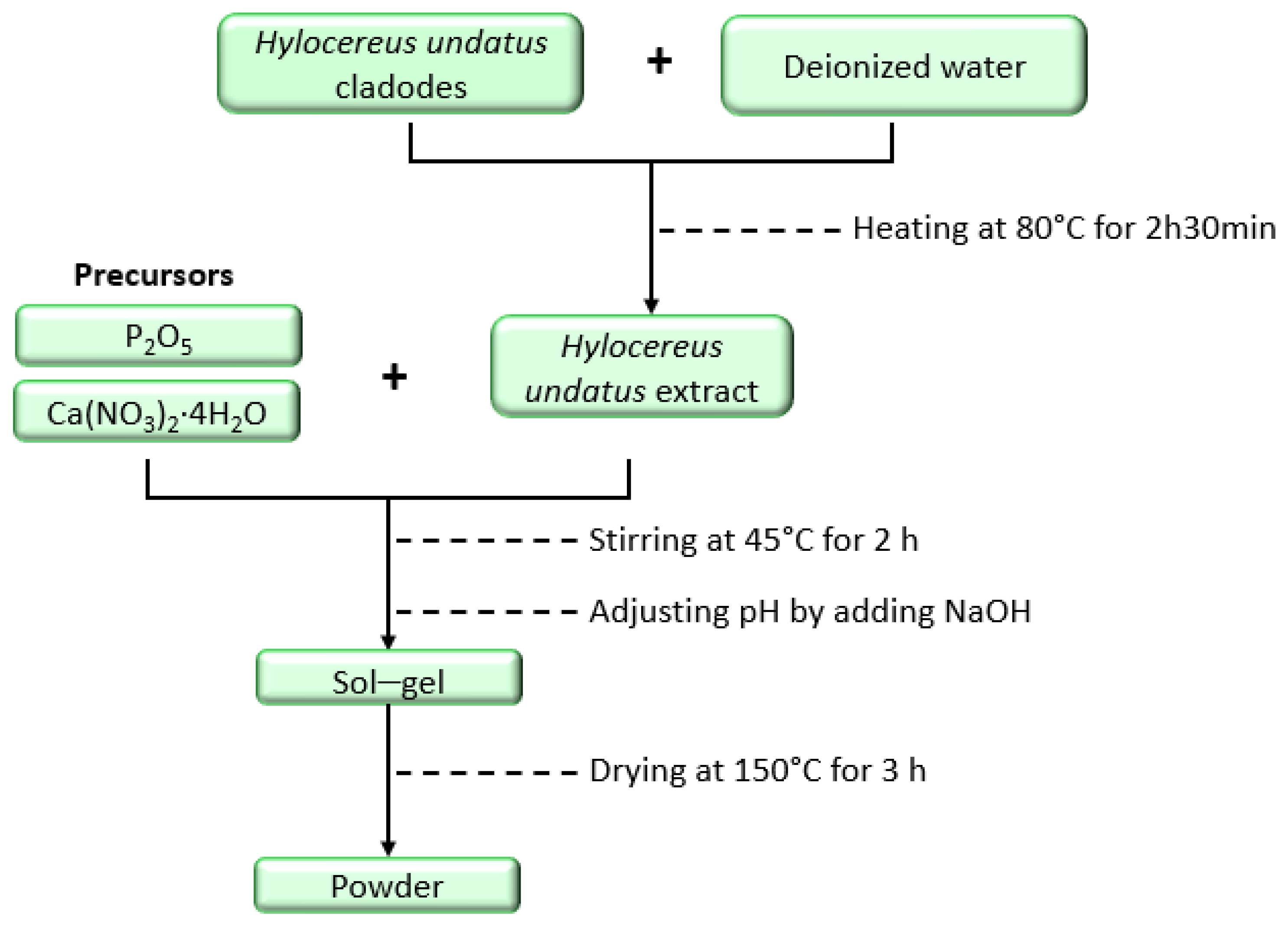
2.2. Synthesis of Hydroxyapatite
2.3. Pre-Treatment of the Titanium Plate
2.4. Electrophoretic Deposition Procedure
2.5. Characterization Techniques
2.6. Bioactivity Experiments
2.7. Antibacterial Activity
2.7.1. Halo Inhibition Assay and SEM Analysis
2.7.2. Quantitative CFU Counting
2.8. Statistical Analysis
3. Results
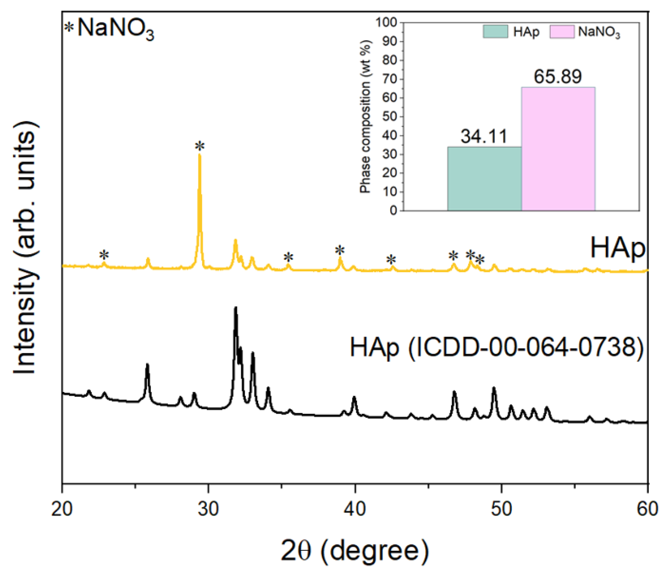
3.1. Characterization of Hydroxyapatite
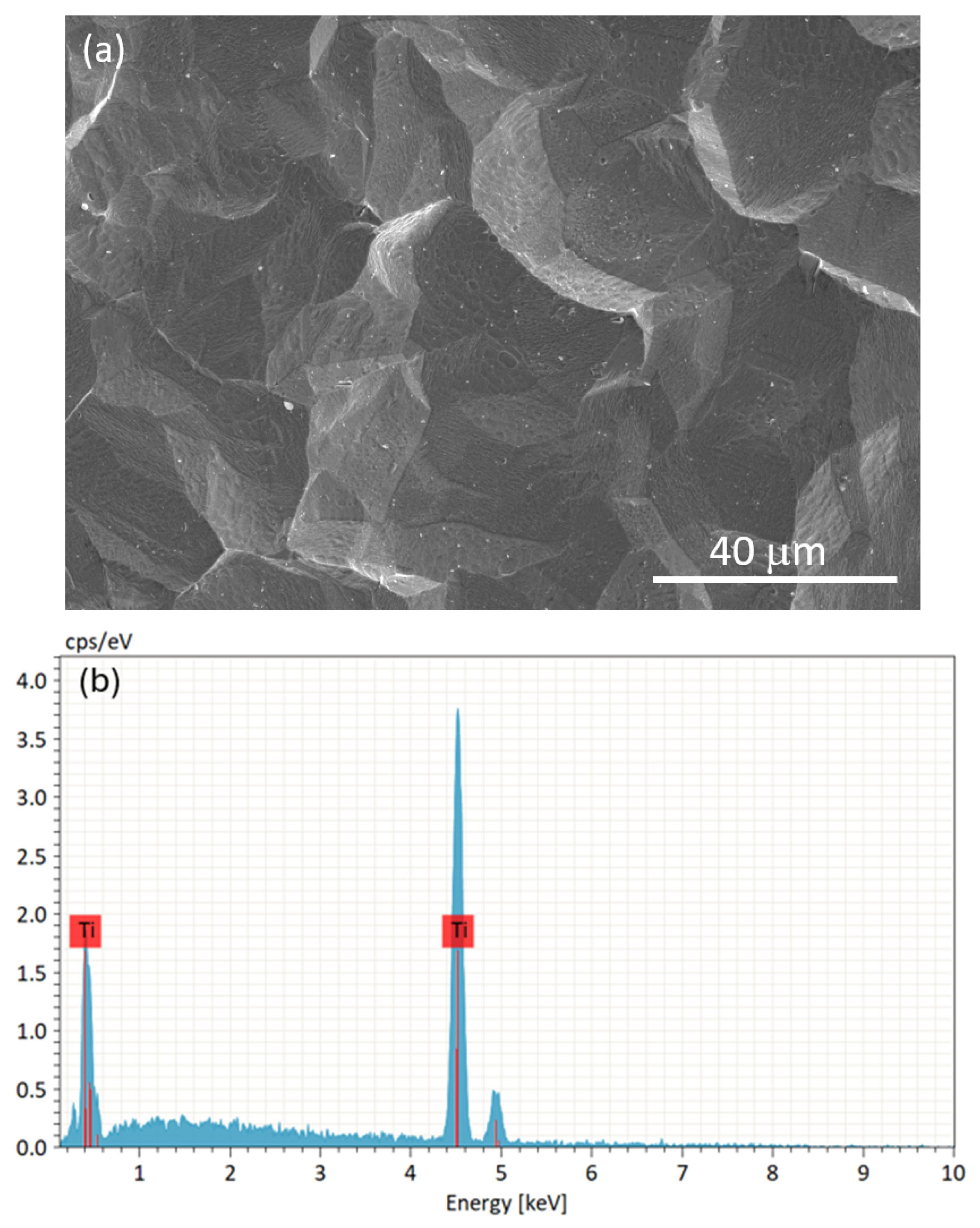
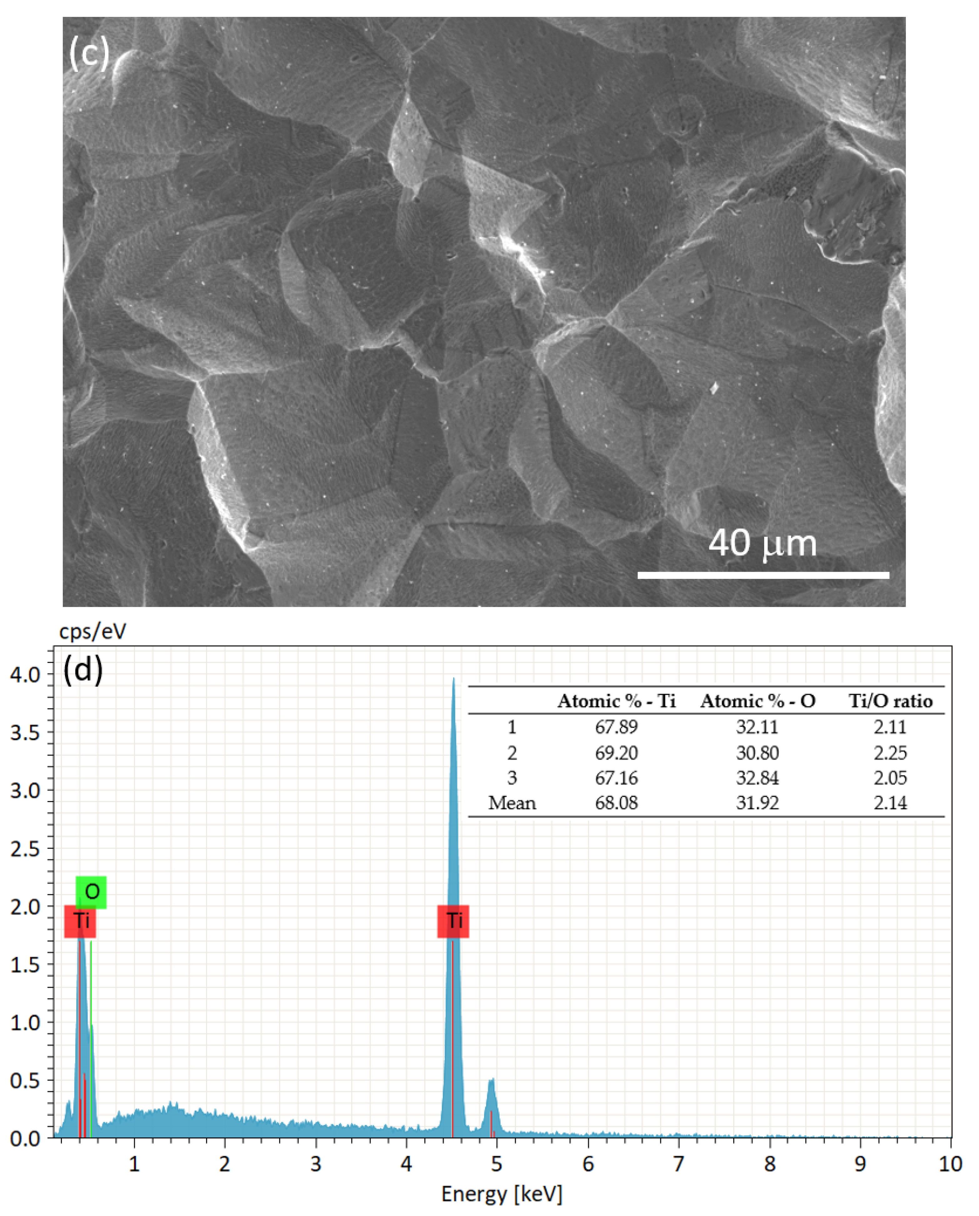
3.2. Characterization of the Substrate and Pre-Coating Layer
3.3. Characterization of Coatings
3.4. Bioactivity Response
3.5. Antibacterial Activity
4. Conclusions
Author Contributions
Funding
Institutional Review Board Statement
Informed Consent Statement
Data Availability Statement
Conflicts of Interest
References
- Benea, L.; Danaila, E.; Ponthiaux, P. Effect of Titania Anodic Formation and Hydroxyapatite Electrodeposition on Electrochemical Behaviour of Ti-6Al-4V Alloy under Fretting Conditions for Biomedical Applications. Corros. Sci. 2015, 91, 262–271. [Google Scholar] [CrossRef]
- Marin, E.; Lanzutti, A. Biomedical Applications of Titanium Alloys: A Comprehensive Review. Materials 2024, 17, 114. [Google Scholar] [CrossRef] [PubMed]
- Cui, C.; Hu, B.M.; Zhao, L.; Liu, S. Titanium Alloy Production Technology, Market Prospects and Industry Development. Mater. Des. 2011, 32, 1684–1691. [Google Scholar] [CrossRef]
- Liu, S.; Shin, Y.C. Additive Manufacturing of Ti6Al4V Alloy: A Review. Mater. Des. 2019, 164, 107552. [Google Scholar] [CrossRef]
- Ehlert, M.; Radtke, A.; Bartmański, M.; Piszczek, P. Evaluation of the Cathodic Electrodeposition Effectiveness of the Hydroxyapatite Layer Used in Surface Modification of Ti6Al4V-Based Biomaterials. Materials 2022, 15, 6925. [Google Scholar] [CrossRef]
- Azari, R.; Rezaie, H.R.; Khavandi, A. Effect of Titanium Dioxide Intermediate Layer on Scratch and Corrosion Resistance of Sol–Gel-Derived HA Coating Applied on Ti-6Al-4V Substrate. Prog. Biomater. 2021, 10, 259–269. [Google Scholar] [CrossRef]
- Pokhrel, S. Hydroxyapatite: Preparation, Properties and Its Biomedical Applications. Adv. Chem. Eng. Sci. 2018, 08, 225–240. [Google Scholar] [CrossRef]
- Figueroa, I.A.; Novelo-Peralta, O.; Flores-Morales, C.; González-Tenorio, R.; Piña-Barba, M.C. Synthesis and Characterization of Biocompatible-Nanohydroxyapatite Crystals Obtained by a Modified Sol-Gel Processing. Biomatter 2012, 2, 71–76. [Google Scholar] [CrossRef]
- Alorku, K.; Manoj, M.; Yuan, A. A Plant-Mediated Synthesis of Nanostructured Hydroxyapatite for Biomedical Applications: A Review. RSC Adv. 2020, 10, 40923–40939. [Google Scholar] [CrossRef]
- Baladi, M.; Amiri, M.; Mohammadi, P.; Salih Mahdi, K.; Golshani, Z.; Razavi, R.; Salavati-Niasari, M. Green Sol–Gel Synthesis of Hydroxyapatite Nanoparticles Using Lemon Extract as Capping Agent and Investigation of Its Anticancer Activity against Human Cancer Cell Lines (T98, and SHSY5). Arab. J. Chem. 2023, 16, 104646. [Google Scholar] [CrossRef]
- Dorozhkin, S.V.; Kharissova, O.V.; Kharisov, B.I. Luminescent Calcium Orthophosphate (CaPO4) Bioceramics: Preparation, Properties and Biomedical Applications. Ceram. Int. 2025, 51, 6837–6851. [Google Scholar] [CrossRef]
- Gopi, D.; Bhuvaneshwari, N.; Indira, J.; Kanimozhi, K.; Kavitha, L. A Novel Green Template Assisted Synthesis of Hydroxyapatite Nanorods and Their Spectral Characterization. Spectrochim. Acta A Mol. Biomol. Spectrosc. 2013, 107, 196–202. [Google Scholar] [CrossRef] [PubMed]
- Dorozhkin, S.V. Calcium Orthophosphate-Based Bioceramics. Materials 2013, 6, 3840–3942. [Google Scholar] [CrossRef] [PubMed]
- Neiva, J.; Benzarti, Z.; Carvalho, S.; Devesa, S. Green Synthesis of CuO Nanoparticles—Structural, Morphological, and Dielectric Characterization. Materials 2024, 17, 5709. [Google Scholar] [CrossRef]
- Nguyen, N.T.T.; Nguyen, L.M.; Nguyen, T.T.T.; Tran, U.P.N.; Nguyen, D.T.C.; Tran, T. Van A Critical Review on the Bio-Mediated Green Synthesis and Multiple Applications of Magnesium Oxide Nanoparticles. Chemosphere 2023, 312, 137301. [Google Scholar] [CrossRef]
- Oh, J.-S.; Jang, J.-H.; Lee, E.-J.; Electrophoretic, E. Electrophoretic Deposition of a Hybrid Graphene Oxide/Biomolecule Coating Facilitating Controllable Drug Loading and Release. Metals 2021, 11, 899. [Google Scholar] [CrossRef]
- Pani, R.; Ranjan Behera, R.; Roy, S. Electrophoretic Deposition of Hydroxyapatite Coating: A State of Art. Mater. Today Proc. 2022, 62, 4086–4093. [Google Scholar] [CrossRef]
- Farrokhi-Rad, M.; Loghmani, S.K.; Shahrabi, T.; Khanmohammadi, S. Electrophoretic Deposition of Hydroxyapatite Nanostructured Coatings with Controlled Porosity. J. Eur. Ceram. Soc. 2014, 34, 97–106. [Google Scholar] [CrossRef]
- Boccaccini, A.R.; Keim, S.; Ma, R.; Li, Y.; Zhitomirsky, I. Electrophoretic Deposition of Biomaterials. J. R. Soc. Interface 2010, 7, S581–S613. [Google Scholar] [CrossRef]
- Zhitomisky, I. Electrophoretic Deposition of Hydroxyapatite. J. Mater. Sci. Mater. Med. 1997, 8, 213–219. [Google Scholar] [CrossRef]
- Sobieszczyk, S. Hydroxyapatite Coatings on Porous Ti and Ti Alloys. Adv. Mater. Sci. 2010, 10, 19–28. [Google Scholar] [CrossRef]
- Aviles, T.; Hsu, S.M.; Clark, A.; Ren, F.; Fares, C.; Carey, P.H.; Esquivel-Upshaw, J.F. Hydroxyapatite Formation on Coated Titanium Implants Submerged in Simulated Body Fluid. Materials 2020, 13, 5593. [Google Scholar] [CrossRef] [PubMed]
- Visentin, F.; El Habra, N.; Fabrizio, M.; Brianese, N.; Gerbasi, R.; Nodari, L.; Zin, V.; Galenda, A. TiO2-HA Bi-Layer Coatings for Improving the Bioactivity and Service-Life of Ti Dental Implants. Surf. Coat. Technol. 2019, 378, 125049. [Google Scholar] [CrossRef]
- Beck, U.; Reiners, G.; Kopacz, U.; Jehn, H.A. Decorative Hard Coatings: Interdependence of Optical, Stoichiometric and Structural Properties. Surf. Coat. Technol. 1993, 60, 389–395. [Google Scholar] [CrossRef]
- Mendes, S.; Kurapova, O.; Faia, P.; Pazheltsev, V.; Zaripov, A.; Konakov, V. Polyantimonic Acid-Based Materials Evaluated as Moisture Sensors at Ambient Temperature. J. Solid State Electrochem. 2023, 27, 611–625. [Google Scholar] [CrossRef]
- ISO 23317:2014; Implants for Surgery—In Vitro Evaluation for Apatite-Forming Ability of Implant Materials. International Organization for Standardization (ISO): Geneva, Switzerland, 2014. Available online: https://www.iso.org/standard/65054.html (accessed on 18 June 2025).
- Kokubo, T.; Takadama, H. Simulated Body Fluid (SBF) as a Standard Tool to Test the Bioactivity of Implants. In Handbook of Biomineralization: Biological Aspects and Structure Formation; Wiley Online Library: Hoboken, NJ, USA, 2007; Volume 3, pp. 97–109. [Google Scholar] [CrossRef]
- Santo, D.; Rodarte, M.; Andreto, C.; Cavaleiro, D.; Carvalho, I.; Balestra, R.; Carvalho, S. Multifunctional Alumina Scaffolds with Enhanced Bioactivity and Antimicrobial Properties for Bone Tissue Engineering. Ceram. Int. 2025, 51, 6155–6165. [Google Scholar] [CrossRef]
- Dev, P.R.; Anand, C.P.; Michael, D.S.; Wilson, P. Hydroxyapatite Coatings: A Critical Review on Electrodeposition Parametric Variations Influencing Crystal Facet Orientation Towards Enhanced Electrochemical Sensing. Mater. Adv. 2022, 3, 7773–7809. [Google Scholar] [CrossRef]
- Büyüksağiş, A.; Bulut, E.; Kayalı, Y. Corrosion Behaviors of Hydroxyapatite Coated by Electrodeposition Method of Ti6Al4V, Ti and AISI 316L SS Substrates. Prot. Met. Phys. Chem. Surf. 2013, 49, 776–787. [Google Scholar] [CrossRef]
- Bishop, J.L.; King, S.J.; Lane, M.D.; Brown, A.J.; Lafuente, B.; Hiroi, T.; Roberts, R.; Swayze, G.A.; Lin, J.F.; Sánchez Román, M. Spectral Properties of Anhydrous Carbonates and Nitrates. Earth Space Sci. 2021, 8, e2021EA001844. [Google Scholar] [CrossRef]
- Diamanti, M.V.; Del Curto, B.; Pedeferri, M.P. Interference Colors of Thin Oxide Layers on Titanium. Color Res. Appl. 2008, 33, 221–228. [Google Scholar] [CrossRef]
- Gao, X.; Zhang, Z.; Liu, L.; Tao, C. Microstructure and Coloration Mechanism of TC11 Aerospace Titanium Alloy Ultra-Thin Thermal Oxide Films. J. Mater. Res. Technol. 2024, 30, 5312–5322. [Google Scholar] [CrossRef]
- Cridling, Q.; Charriere, R.; Jamon, D.; Lenci, M.; Pedeferri, M.P.; Delafosse, D. Anodized Titanium Oxide Thickness Estimation with Ellipsometry, Reflectance Spectra Extrema Positions and Electronic Imaging: Importance of the Interfaces Electromagnetic Phase-Shift. Thin Solid Film. 2020, 709, 138181. [Google Scholar] [CrossRef]
- Keren, Z.; Shuai, T.; Yuzhe, Z.; Junli, H.; Nailu, Z.; Lei, W.; Xiaoyong, Z. Oxidation Characteristics of Ti-6Al-4V Machining Scraps and Their Influence on Microstructure and Fracture Behavior in Recycled Alloys. Mater. Des. 2025, 254, 114137. [Google Scholar] [CrossRef]
- Santos, G.; Benzarti, Z.; Cavaleiro, D.; Figueiredo, L.; Carvalho, S.; Devesa, S. Optimization of Black Nickel Coatings’ Electrodeposit onto Steel. Coatings 2024, 14, 1125. [Google Scholar] [CrossRef]
- Griber, Y.A.; Samoilova, T.; Al-Rasheed, A.S.; Bogushevskaya, V.; Cordero-Jahr, E.; Delov, A.; Gouaich, Y.; Manteith, J.; Mefoh, P.; Odetti, J.V.; et al. “Playing” with Color: How Similar Is the “Geometry” of Color Harmony in the CIELAB Color Space Across Countries? Arts 2024, 13, 53. [Google Scholar] [CrossRef]
- Mazza, T.; Barborini, E.; Piseri, P.; Milani, P.; Cattaneo, D.; Li Bassi, A.; Bottani, C.E.; Ducati, C. Raman Spectroscopy Characterization of TiO2 Rutile Nanocrystals. Phys. Rev. B Condens. Matter Mater. Phys. 2007, 75, 045416. [Google Scholar] [CrossRef]
- Kernazhitsky, L.; Shymanovska, V.; Gavrilko, T.; Naumov, V.; Fedorenko, L.; Kshnyakin, V.; Baran, J. Laser-Excited Excitonic Luminescence of Nanocrystalline TiO2 Powder. Ukr. J. Phys. 2014, 59, 246–253. [Google Scholar] [CrossRef]
- Challagulla, S.; Tarafder, K.; Ganesan, R.; Roy, S. Structure Sensitive Photocatalytic Reduction of Nitroarenes over TiO2. Sci. Rep. 2017, 7, 8783. [Google Scholar] [CrossRef]
- Sacco, A.; Mandrile, L.; Tay, L.L.; Itoh, N.; Raj, A.; Moure, A.; Del Campo, A.; Fernandez, J.F.; Paton, K.R.; Wood, S.; et al. Quantification of Titanium Dioxide (TiO2) Anatase and Rutile Polymorphs in Binary Mixtures by Raman Spectroscopy: An Interlaboratory Comparison. Metrologia 2023, 60, 055011. [Google Scholar] [CrossRef]
- Dorozhkin, S.V. Dissolution Mechanism of Calcium Apatites in Acids: A Review of Literature. World J. Methodol. 2012, 2, 1–17. [Google Scholar] [CrossRef]
- Brown, P.W.; Martin, R.I. An Analysis of Hydroxyapatite Surface Layer Formation. J. Phys. Chem. B 1999, 103, 1671–1675. [Google Scholar] [CrossRef]
- Rodríguez-Lugo, V.; Karthik, T.V.K.; Mendoza-Anaya, D.; Rubio-Rosas, E.; Villaseñor Cerón, L.S.; Reyes-Valderrama, M.I.; Salinas-Rodríguez, E. Wet Chemical Synthesis of Nanocrystalline Hydroxyapatite Flakes: Effect of PH and Sintering Temperature on Structural and Morphological Properties. R. Soc. Open Sci. 2018, 5, 180962. [Google Scholar] [CrossRef] [PubMed]
- Ciobanu, C.S.; Massuyeau, F.; Constantin, L.V.; Predoi, D. Structural and Physical Properties of Antibacterial Ag-Doped Nano-Hydroxyapatite Synthesized at 100 °C. Nanoscale Res. Lett. 2011, 6, 613. [Google Scholar] [CrossRef] [PubMed]
- Gupta, A.; Prasad, A.; Mulchandani, N.; Shah, M.; Ravi Sankar, M.; Kumar, S.; Katiyar, V. Multifunctional Nanohydroxyapatite-Promoted Toughened High-Molecular-Weight Stereocomplex Poly(Lactic Acid)-Based Bionanocomposite for Both 3D-Printed Orthopedic Implants and High-Temperature Engineering Applications. ACS Omega 2017, 2, 4039–4052. [Google Scholar] [CrossRef]
- Timchenko, P.E.; Timchenko, E.V.; Pisareva, E.V.; Vlasov, M.Y.; Red’Kin, N.A.; Frolov, O.O. Spectral Analysis of Allogeneic Hydroxyapatite Powders. Proc. J. Phys. Conf. Ser. 2017, 784, 012060. [Google Scholar]
- Jaber, H.L.; Hammood, A.S.; Parvin, N. Synthesis and Characterization of Hydroxyapatite Powder from Natural Camelus Bone. J. Aust. Ceram. Soc. 2018, 54, 1–10. [Google Scholar] [CrossRef]
- Das, A.; Dobbidi, P. Impedance Spectroscopy and Ac Conductivity in Ba0.5Sr0.5TiO3–Ca10(PO4)6(OH)2 Ceramic Composites: An Electrical Approach to Unveil Biocomposites. ACS Biomater. Sci. Eng. 2021, 7, 2296–2308. [Google Scholar] [CrossRef]
- Aaron, R.K.; Ciombor, D.M.; Simon, B.J. Treatment of Nonunions with Electric and Electromagnetic Fields. Clin. Orthop. Relat. Res. 2004, 419, 21–29. [Google Scholar] [CrossRef]
- Saberi, A.; Jabbari, F.; Zarrintaj, P.; Saeb, M.R.; Mozafari, M. Electrically Conductive Materials: Opportunities and Challenges in Tissue Engineering. Biomolecules 2019, 9, 448. [Google Scholar] [CrossRef]
- Devesa, S.; Graça, M.P.; Costa, L.C. Impedance Spectroscopy Characterization of a Niobate Material for RF Applications. In Advances in Chemistry Research; Taylor, J.C., Ed.; Nova Science Publishers: Hauppauge, NY, USA, 2022; Volume 76, ISBN 979-8-88697-378-5. [Google Scholar]
- Alim, M.A.; Khanam, S.; Seitz, M.A. Immittance Spectroscopy of Smart Components and Novel Devices. Act. Passiv. Electron. Compon. 1994, 16, 153–170. [Google Scholar] [CrossRef]
- Tayebi; Shahini, A.; Yazdimamaghani, M.; Walker, K.J.; Eastman, M.; Hatami-Marbini, H.; Smith, B.; Ricci, J.L.; Madihally, S.; Vashaee, D. 3D Conductive Nanocomposite Scaffold for Bone Tissue Engineering. Int. J. Nanomed. 2013, 9, 167–181. [Google Scholar] [CrossRef]
- Baino, F.; Yamaguchi, S. The Use of Simulated Body Fluid (SBF) for Assessing Materials Bioactivity in the Context of Tissue Engineering: Review and Challenges. Biomimetics 2020, 5, 57. [Google Scholar] [CrossRef]
- Oliveira, W.F.; Silva, P.M.S.; Silva, R.C.S.; Silva, G.M.M.; Machado, G.; Coelho, L.C.B.B.; Correia, M.T.S. Staphylococcus Aureus and Staphylococcus Epidermidis Infections on Implants. J. Hosp. Infect. 2018, 98, 111–117. [Google Scholar] [CrossRef] [PubMed]
- Kumaravel, V.; Nair, K.M.; Mathew, S.; Bartlett, J.; Kennedy, J.E.; Manning, H.G.; Whelan, B.J.; Leyland, N.S.; Pillai, S.C. Antimicrobial TiO2 Nanocomposite Coatings for Surfaces, Dental and Orthopaedic Implants. Chem. Eng. J. 2021, 416, 129071. [Google Scholar] [CrossRef] [PubMed]
- Liu, L.; Bhatia, R.; Webster, T.J. Atomic Layer Deposition of Nano-TiO2 Thin Films with Enhanced Biocompatibility and Antimicrobial Activity for Orthopedic Implants. Int. J. Nanomed. 2017, 12, 8711–8723. [Google Scholar] [CrossRef] [PubMed]
- Kamphof, R.; Lima, R.N.O.; Schoones, J.W.; Arts, J.J.; Nelissen, R.G.H.H.; Cama, G.; Pijls, B.G.C.W. Antimicrobial Activity of Ion-Substituted Calcium Phosphates: A Systematic Review. Heliyon 2023, 9, e16568. [Google Scholar] [CrossRef]
- Havas, F.; Krispin, S.; Cohen, M.; Attia-Vigneau, J. A Hylocereus Undatus Extract Enhances Skin Microbiota Balance and Delivers In-Vivo Improvements in Skin Health and Beauty. Cosmetics 2024, 11, 39. [Google Scholar] [CrossRef]
- Canute Kamikawachi, R.; Carrara, V.; Vilegas, W. Dragon Fruit Farming By-Products as an Important Source of Several Glycosylated Flavonoids. Food Res. Int. 2023, 173, 113400. [Google Scholar] [CrossRef]


| I (mA) | u (V) | T (°C) | w (rpm) | t (hours) |
|---|---|---|---|---|
| 50 | 3.7 | 55 | 200 | 2 |
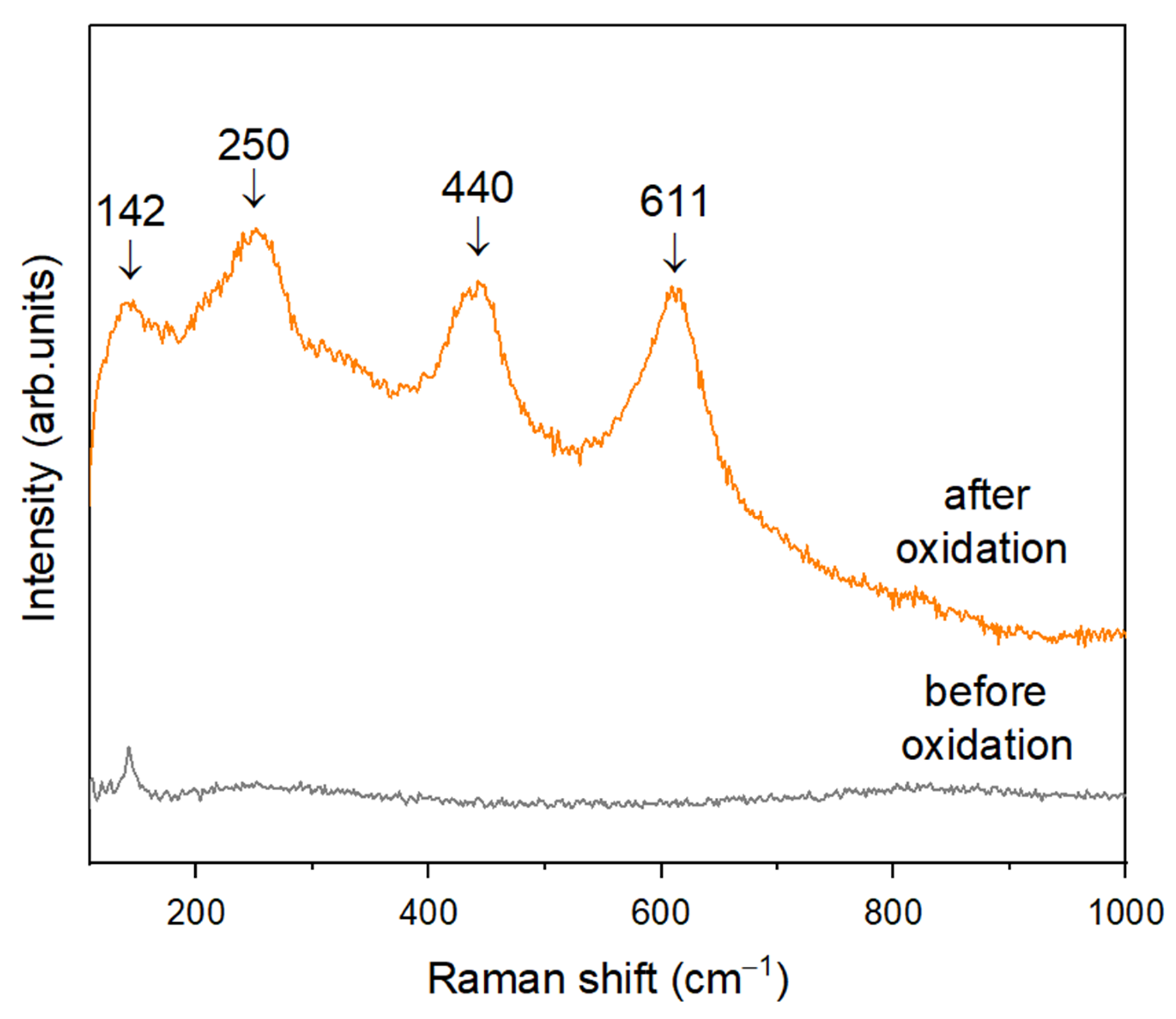
| Experimental (cm−1) | Challagulla et al. [40] (cm−1) | Kernazhitsky et al. [39] (cm−1) | Mazza et al. [38] (cm−1) | Sacco et al. [41] (cm−1) | Band Assignment |
|---|---|---|---|---|---|
| 142 | 140 | 144 | - | 143 | B1g |
| 250 | 230 | 235 | - | 235 | - |
| 440 | 430 | 445 | 447 | 447 | Eg |
| 611 | 590 | 610 | 612 | 612 | A1g |
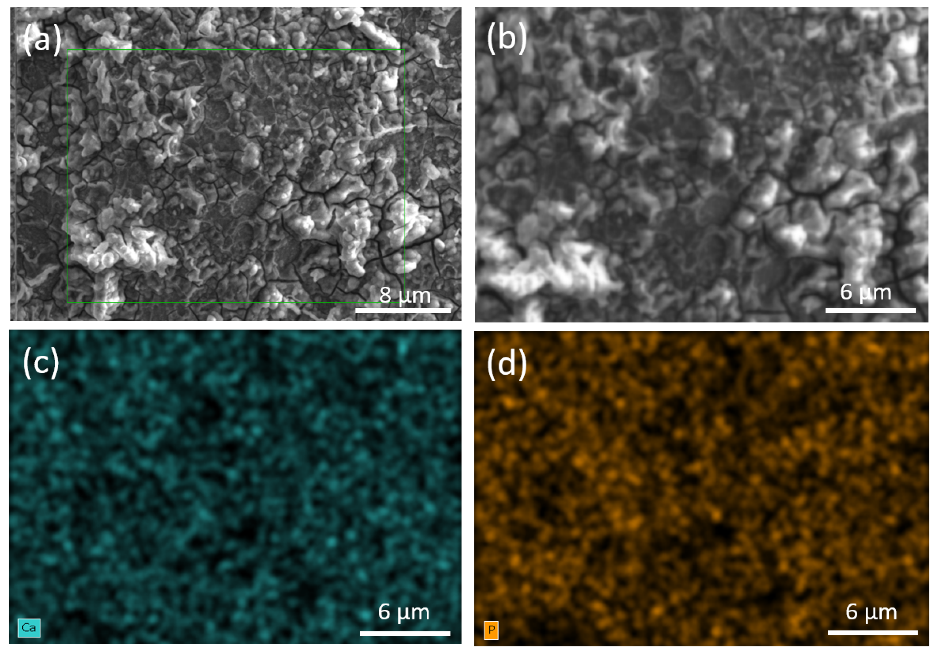
| Region | Atomic % Ca | Atomic % P | Ca/P Ratio |
|---|---|---|---|
| 1 | 65.16 | 34.84 | 1.87 |
| 2 | 65.30 | 34.70 | 1.88 |
| 3 | 65.62 | 34.38 | 1.90 |
Disclaimer/Publisher’s Note: The statements, opinions and data contained in all publications are solely those of the individual author(s) and contributor(s) and not of MDPI and/or the editor(s). MDPI and/or the editor(s) disclaim responsibility for any injury to people or property resulting from any ideas, methods, instructions or products referred to in the content. |
© 2025 by the authors. Licensee MDPI, Basel, Switzerland. This article is an open access article distributed under the terms and conditions of the Creative Commons Attribution (CC BY) license (https://creativecommons.org/licenses/by/4.0/).
Share and Cite
Relva, M.; Santo, D.; Alexandre, R.; Faia, P.; Carvalho, S.; Benzarti, Z.; Devesa, S. Electrophoretic Deposition of Green-Synthesized Hydroxyapatite on Thermally Oxidized Titanium: Enhanced Bioactivity and Antibacterial Performance. Appl. Sci. 2025, 15, 8598. https://doi.org/10.3390/app15158598
Relva M, Santo D, Alexandre R, Faia P, Carvalho S, Benzarti Z, Devesa S. Electrophoretic Deposition of Green-Synthesized Hydroxyapatite on Thermally Oxidized Titanium: Enhanced Bioactivity and Antibacterial Performance. Applied Sciences. 2025; 15(15):8598. https://doi.org/10.3390/app15158598
Chicago/Turabian StyleRelva, Mariana, Daniela Santo, Ricardo Alexandre, Pedro Faia, Sandra Carvalho, Zohra Benzarti, and Susana Devesa. 2025. "Electrophoretic Deposition of Green-Synthesized Hydroxyapatite on Thermally Oxidized Titanium: Enhanced Bioactivity and Antibacterial Performance" Applied Sciences 15, no. 15: 8598. https://doi.org/10.3390/app15158598
APA StyleRelva, M., Santo, D., Alexandre, R., Faia, P., Carvalho, S., Benzarti, Z., & Devesa, S. (2025). Electrophoretic Deposition of Green-Synthesized Hydroxyapatite on Thermally Oxidized Titanium: Enhanced Bioactivity and Antibacterial Performance. Applied Sciences, 15(15), 8598. https://doi.org/10.3390/app15158598