1. Introduction
PV energy represents an excellent energy source for remote and standalone systems due to its availability and scalability. It also represents a clean source of energy that continues to grow and contribute to the move to a more balanced energy mix and a sustainable clean future for energy on Earth. From that fact stems the need for efficient energy delivery systems such as inverters, battery chargers, and other power supplies that interface the PV source to the consumer [
1]. In standalone PV systems, PV battery chargers typically use PWM DC/DC converters such as boost or buck–boost converters to charge local batteries [
2,
3]. These basic types of converters are simple and well established in terms of both control simplicity and design, but they have drawbacks such as hard-switching characteristics. In switch-mode DC/DC converters, hard switching refers to the fact that every time the semiconductor switch turns on and off, it loses a considerable amount of power due to having to cut the current or force it to zero immediately [
4]. The switching loss in hard-switched converters limits the switching frequency and therefore the compactness of the system, because the higher the switching frequency, the smaller the passive and energy-storing elements needed [
5]. Several researchers have proposed different soft-switching DC/DC converters for PV applications [
6,
7,
8,
9,
10]. Even though these converters improve the overall efficiency of the system, their control complexity and high number of switches and passive elements make them impractical topologies for PV battery chargers.
Resonant converters present a viable solution for efficiency and compactness due to their ability to utilize resonance to perform switching under soft conditions, a zero voltage, or a zero current [
11]. Several resonant converters have been proposed in the literature for PV applications [
12,
13,
14,
15]. However, these converters rely on isolation transformers, which increase the size and losses of the system. A capacitive isolated resonant converter has not been discussed in the literature for PV applications. A capacitive isolated resonant converter eliminates the need for a transformer; this could significantly reduce magnetic core losses and overall system size, which are important advantages for low-voltage standalone PV applications. Instead, if capacitive galvanic isolation is used, it will provide effective electrical separation between the input and output without bulky magnetic components.
Having a PV system requires having the ability to extract the maximum power available in it, which is a task usually performed by a DC/DC converter. There are multiple methods or control algorithms that can be used to perform maximum power point tracking (MPPT), such as perturb and observe (P&O) algorithms, incremental conductance algorithms, and other algorithms that require some sort of knowledge of the system’s dynamics [
16,
17]. This means that, if a resonant converter is chosen, the control complexity becomes much higher than that of a basic DC/DC converter. This is an essential reason for why boost and buck–boost converters are chosen over more efficient converters. It is the familiarity with the dynamic and linearized models of these converters that makes them desirable for use with conventional MPPT methods. Model-independent MPPT methods present an opportunity to utilize converters that are difficult to linearize and control, such as resonant converters. One of these methods is extremum-seeking control (ESC) [
18,
19].
The ESC method has been utilized in MPPT applications, such as in Refs. [
20,
21,
22]. It offers great advantages, as it does not require previous knowledge of the system’s model or dynamics. However, in the literature, there are no cases that utilize it with more complex converters. Most of the studies conducted with extremum-seeking control in MPPT applications utilize basic converters, which do not utilize the full potential of the algorithm. This paper presents an extremum-seeking solar power optimizer that uses a capacitive isolated series resonant converter for a standalone battery charging application. The proposed system utilizes a transformer-less series resonant converter suitable for low-voltage gain conversion and a model-free ESC algorithm designed specifically for resonant converters. The remainder of this paper is organized as follows:
Section 2 introduces the proposed converter design and its advantages.
Section 3 formulates the ESC algorithm for use with series resonant converters.
Section 4 presents simulation results validating the proposed system.
Section 5 provides a discussion on system performance, robustness, and implementation. Finally,
Section 6 concludes the paper and explores possible future work extensions.
2. Advantages and Design Procedure of Capacitive Isolated Series Resonant Converter
This section, along with
Section 3, forms the core methodology of the proposed system and covers the converter design and control strategy in detail. In most resonant converters, a high-frequency transformer is used to either step up or step down the voltage level, which is suitable for grid-connected applications. Transformers also provide galvanic isolation for the system to separate grounds and enhance electrical safety. However, the high-frequency transformer introduces copper and core losses, and to keep them within acceptable limits, the core size of the transformers will be constrained. Even with an optimized design, the converter will still require multiple magnetic elements. In standalone applications, the PV panel voltage and battery voltage can be scaled to match or closely align. In fact, even if the voltage levels differ by up to a factor of two, a transformer-less converter can still be realized to handle the interface. In addition, the galvanic isolation can be achieved by splitting the capacitor of the resonant tank into two capacitors and lacing one in the outgoing path and the other in the incoming path.
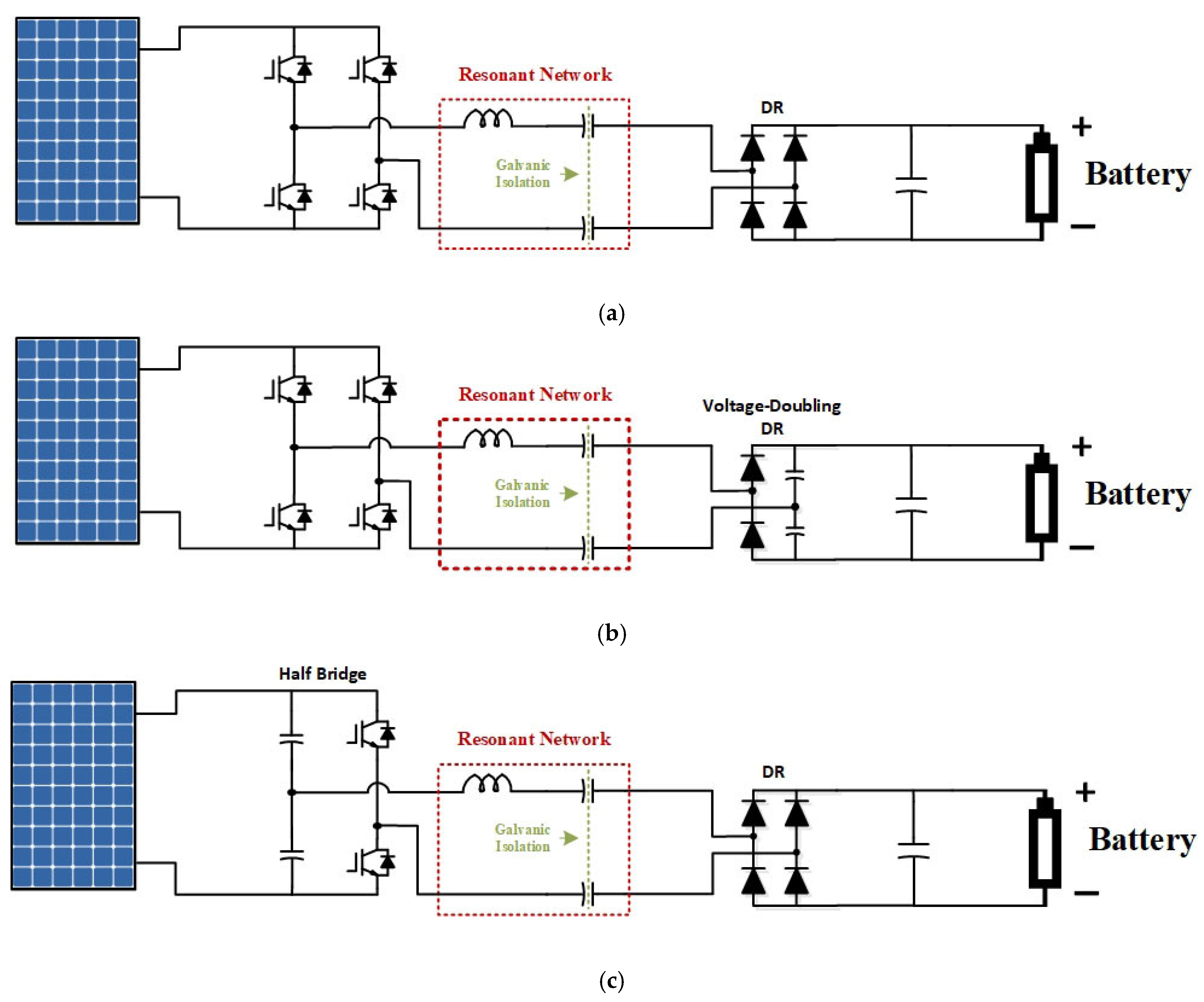
Figure 1 shows the possible choices for PV battery charging using a series resonant converter in standalone applications.
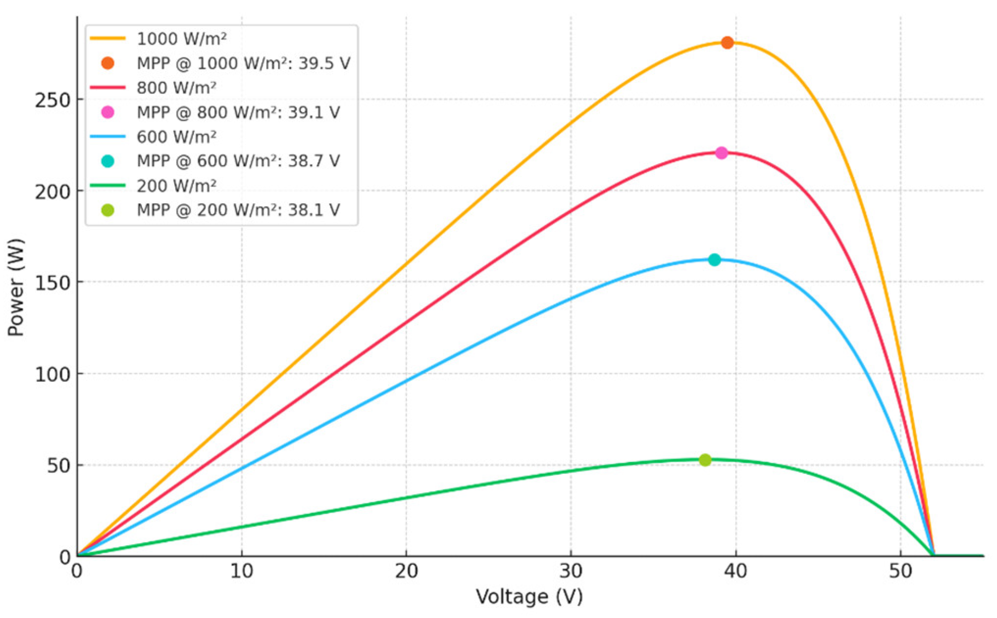
If a series resonant converter is used in this system, its nominal operating point could be carefully chosen to charge the battery with minimal voltage changes, even with extreme irradiation levels affecting the PV panel. This is due to the fact that the maximum power point (MPP) voltage of the PV panel varies only slightly from maximum irradiation to very low irradiation. The battery voltage also varies slightly between low and nominal voltage to full charge levels. These factors make a series resonant converter very suitable for this type of application.
Figure 2 shows the variation in the MPP voltage of the PV panel with respect to irradiation level.
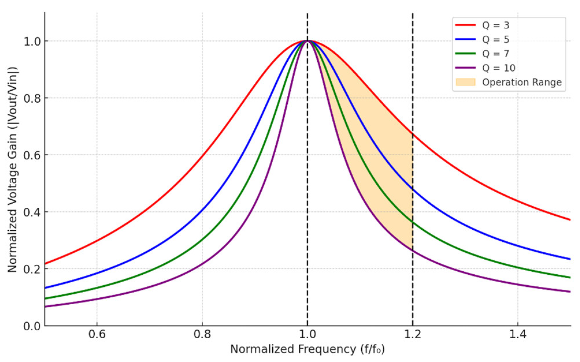
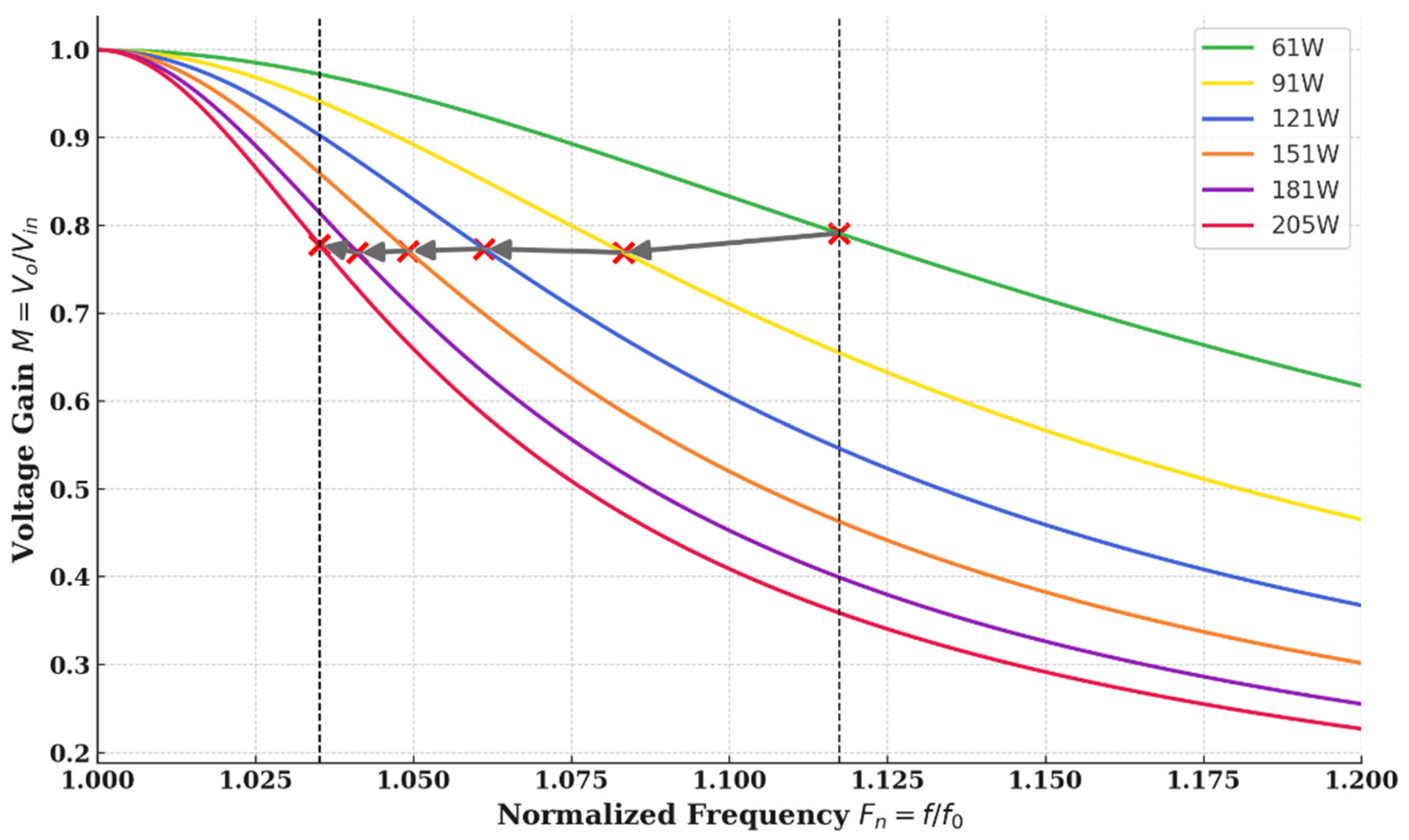
The normalized voltage gain curve of a series resonant converter of a configuration similar to the one in
Figure 1a can be seen in
Figure 3; it shows a possible region of operation for the converter to operate nominally and it also shows that if the nominal operating point is placed at a middle point, the converter will be able to increase or decrease the voltage by a considerable percentage more than required for the PV MPP voltage at different irradiance levels.
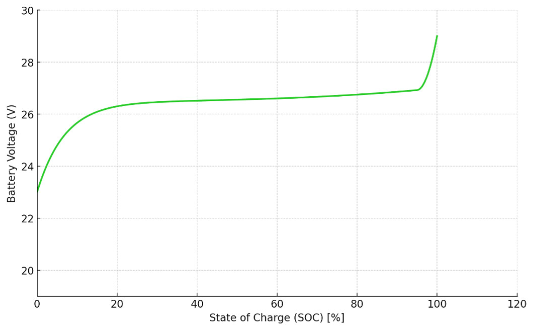
In addition to the PV voltage change, the battery voltage changes with respect to its state of charge.
Figure 4 shows a typical characteristic curve for the battery voltage versus its state of charge (SOC).
While this study focuses on maximum power point tracking using ESC, it is acknowledged that optimal and safe battery charging requires adherence to profiles such as Constant Current (CC) and Constant Voltage (CV). The ESC algorithm does not inherently enforce these profiles, as its primary objective is to maximize power transfer from the PV panel. In real-world systems, such functionality is typically handled by a dedicated battery management system (BMS), which monitors parameters like temperature, state of charge (SOC), and terminal voltage, and can coordinate with or override the MPPT loop if needed.
It can be seen from these curves that a series resonant converter with capacitive galvanic isolation is more than capable of handling the interface between the PV and the battery without the need for a transformer. By removing the transformer, a major part of the converter losses (copper and core) is eliminated or at least reduced. The series resonant converter still retains the other desirable traits of the resonant converter, such as soft switching and galvanic isolation, which will be discussed in the next section. The main advantages of the series resonant converter with capacitive isolation will be presented by first examining the main operating principle of the converter. The configuration in
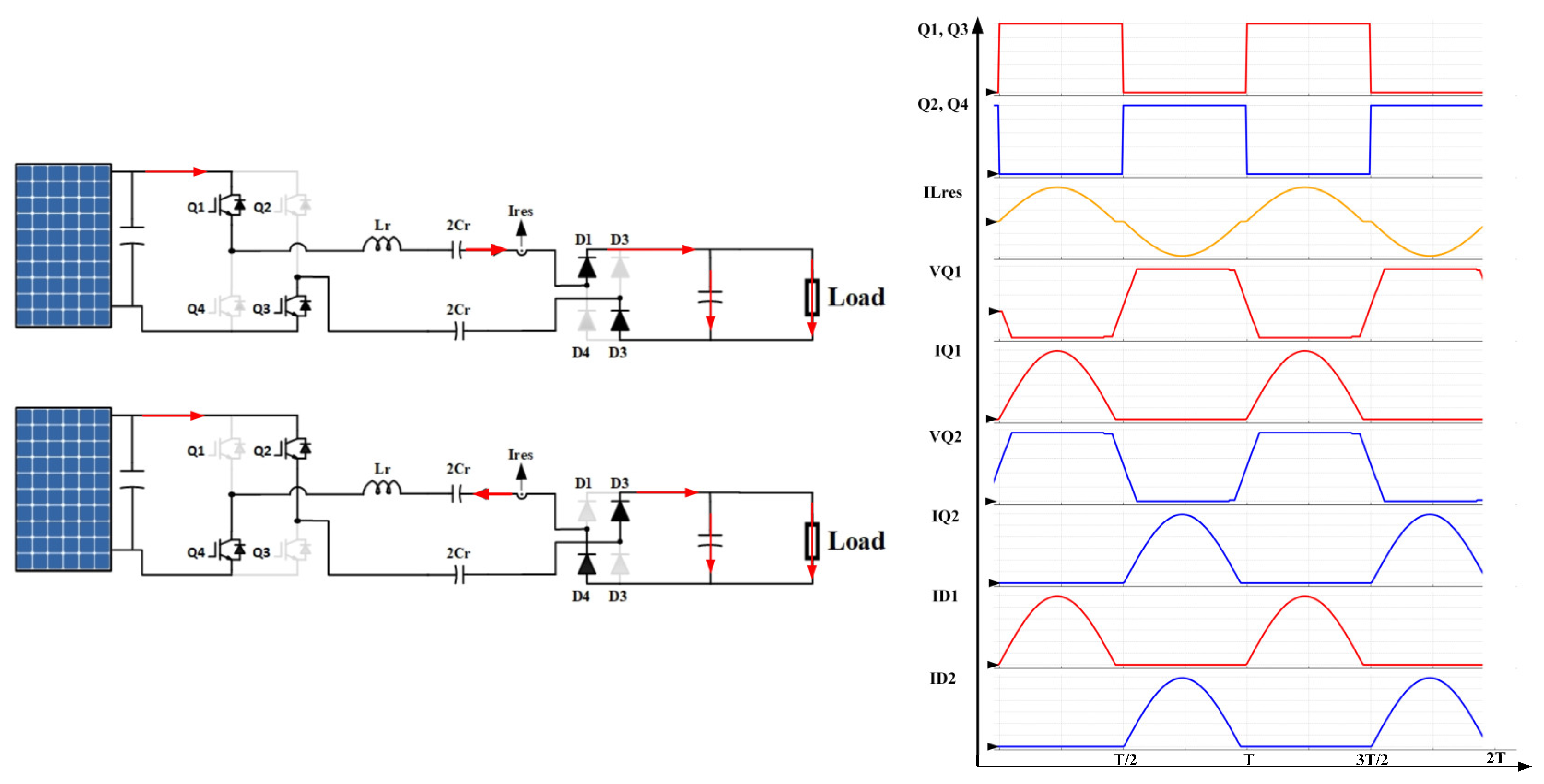
Figure 1a will be taken as an example. The converter has four active switches (Q1–Q4) and four diodes (D1–D4). The switches are operated in pairs, meaning each pair is turned on and off at the same time. When Q1 and Q3 are on, a positive DC voltage is applied to the resonant tank, and a sinusoidal or semi-sinusoidal current will flow through the resonant tank in the outgoing direction. The current will pass through diodes D1 and D3 to charge the output capacitor and load. When Q2 and Q4 are on, a negative DC voltage is applied to the resonant tank, and a sinusoidal or semi-sinusoidal current will flow through the resonant tank in the incoming direction. The current will pass through D2 and D4, also charging the output capacitor and load. The main operation states and the key waveforms are shown in
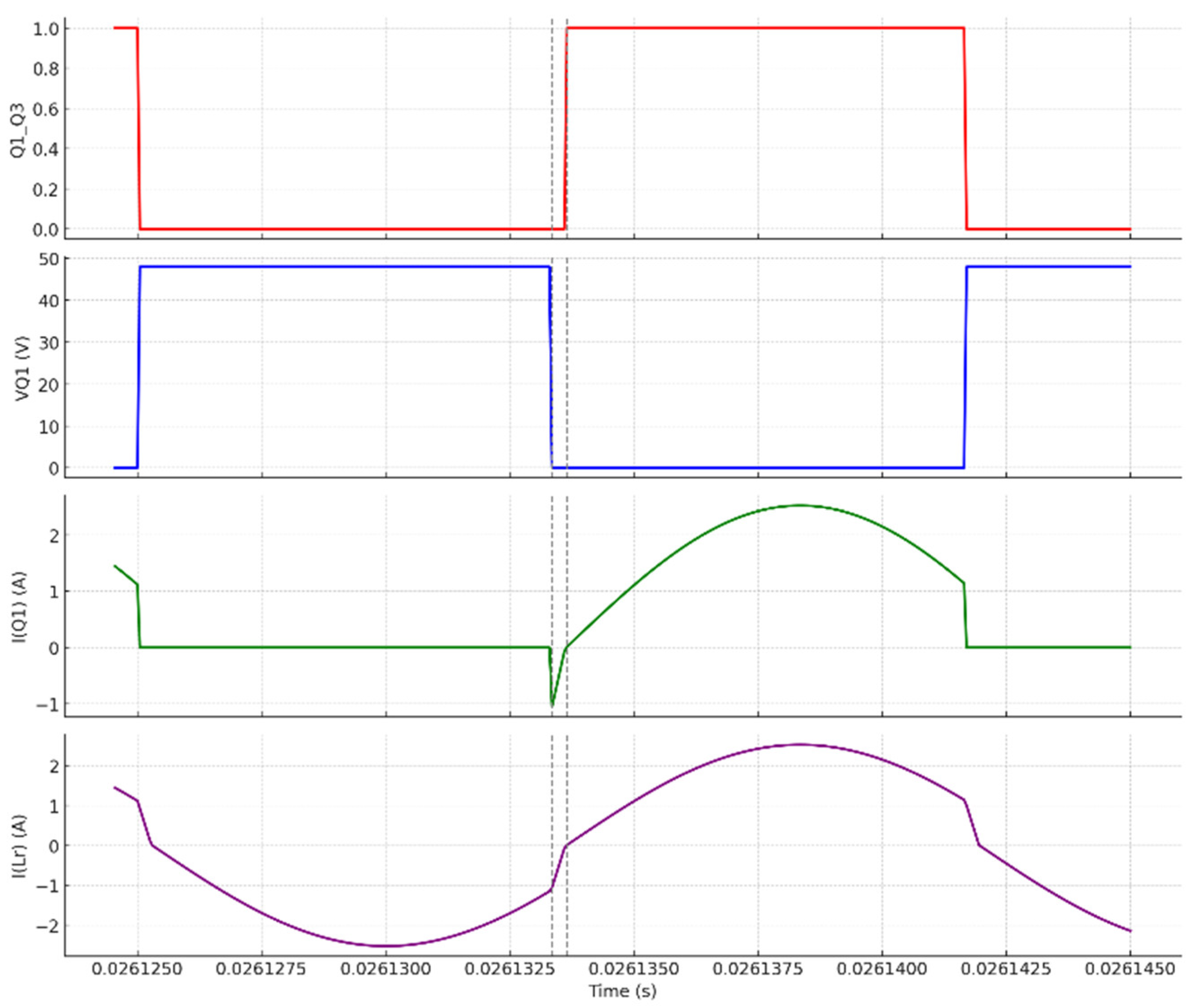
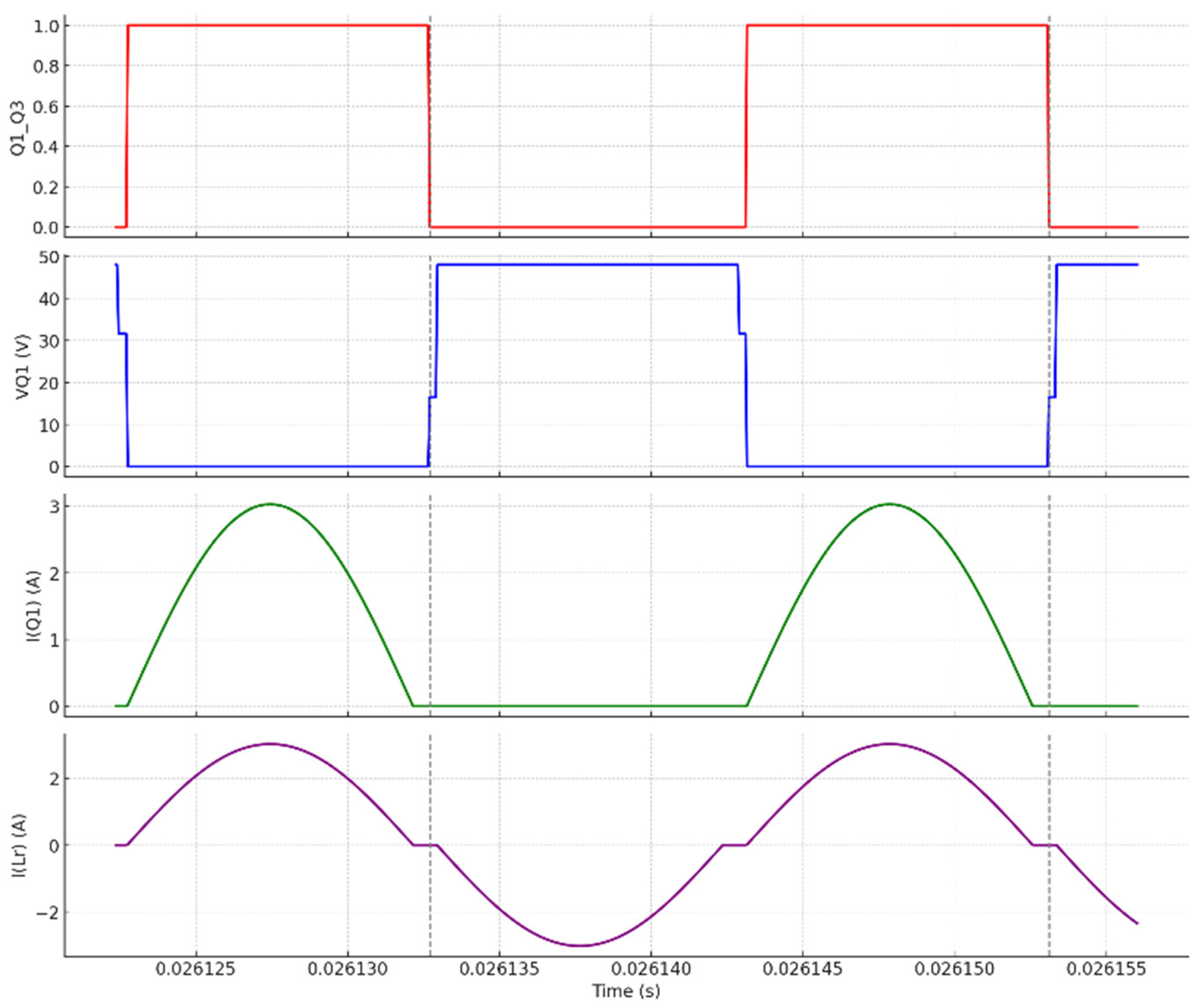
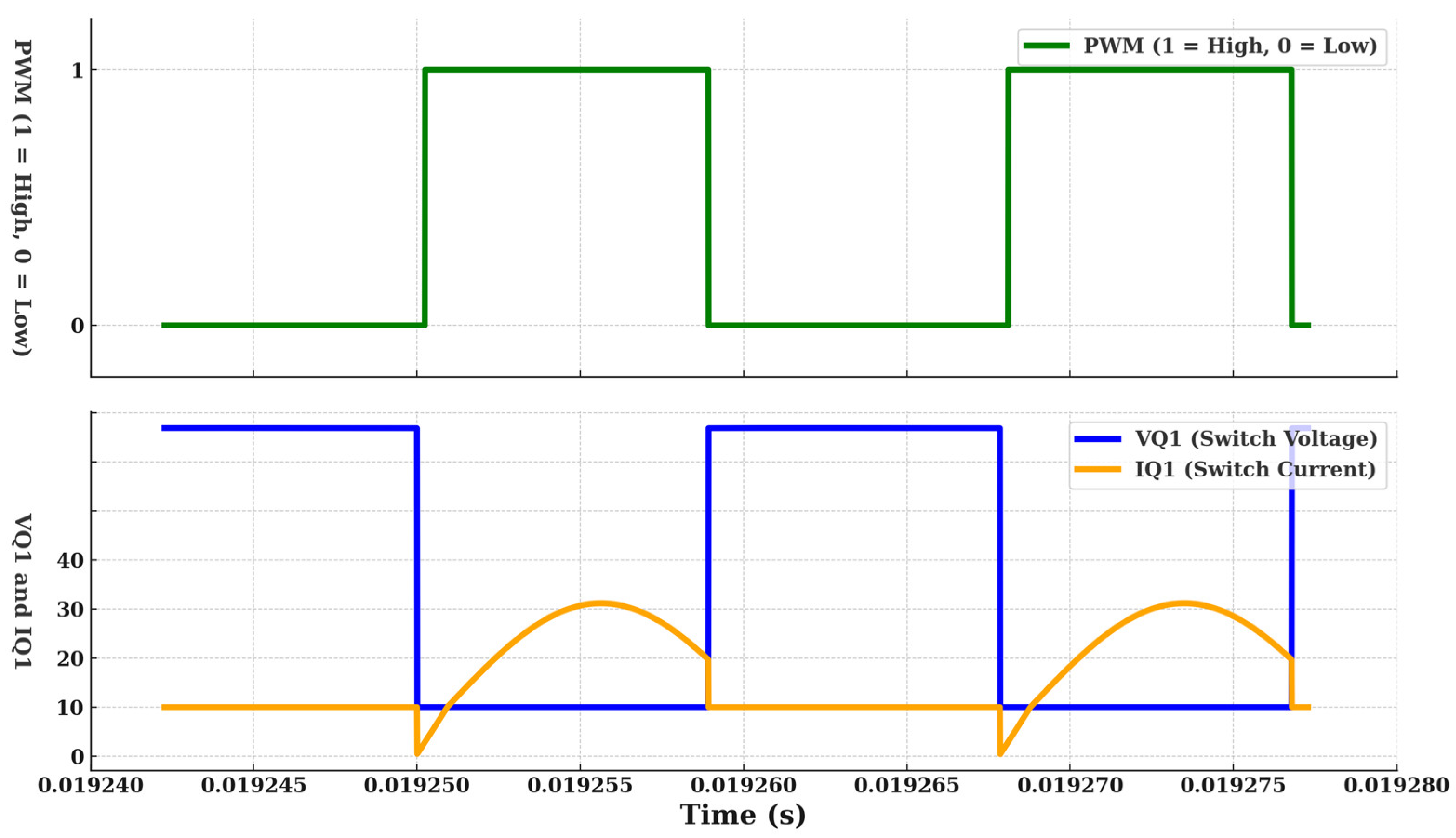
Figure 5, and it can be seen that the current has a semi-sinusoidal waveform. The converter switching frequency can be above, below, or equal to the resonant frequency. When the converter operates above the resonant frequency, it provides zero-voltage switching. This means that when the voltage of the active switch drops to zero before it turns on, and the turn-on switching loss is eliminated.
Figure 6 shows the switch voltage and current waveforms when operated above the resonant frequency. It can be seen that the switch voltage drops to zero before the switch is turned on.
Figure 7 shows that if the converter is operated below the resonant frequency, zero current switching is achieved and the current goes to zero before the switch is turned off, meaning that it is not forced to turn off and turn-off losses are eliminated.
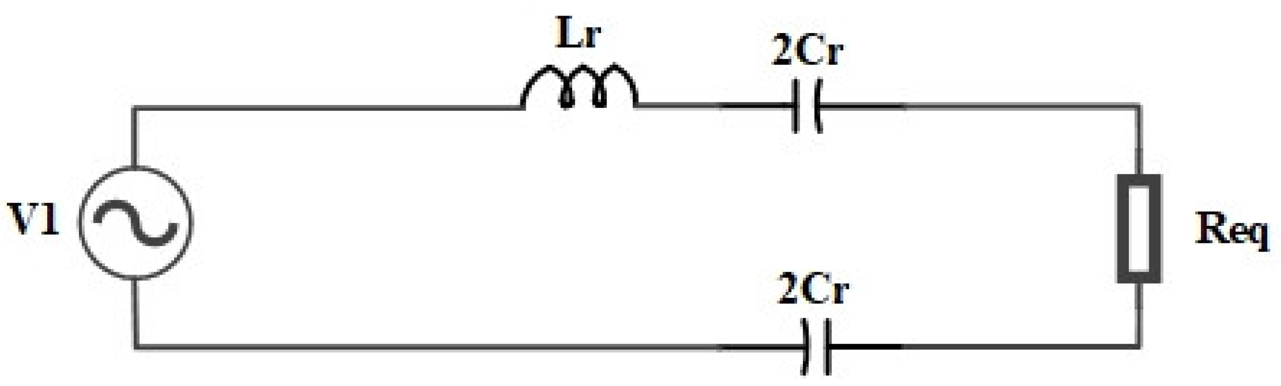
Since the resonant tank only passes a sinusoidal current, a first harmonic approximation (FHA) can be used to analyze the converter. The input voltage can be taken as the fundamental component of the square wave, and the load can be represented as an equivalent series resistance that draws the same amount of power as the load. The system is then simplified to the simple circuit shown in
Figure 8.
The fundamental voltage, the equivalent series resistance, and the voltage gain equations can be defined as follows:
And the voltage gain equation can be re-written as a function of the quality factor (
Q) and the normalized switching frequency factor (
), as follows:
where the Q and
are defined as
Based on these equations, a design procedure can be synthesized for battery charging applications.
If the nominal battery voltage is slightly less than the PV voltage, the configuration in
Figure 1a can be used. If the battery voltage is higher than the PV voltage, the configuration in
Figure 1b can be used because it has the ability to double the output. If the battery voltage is less than half the PV voltage, the configuration in
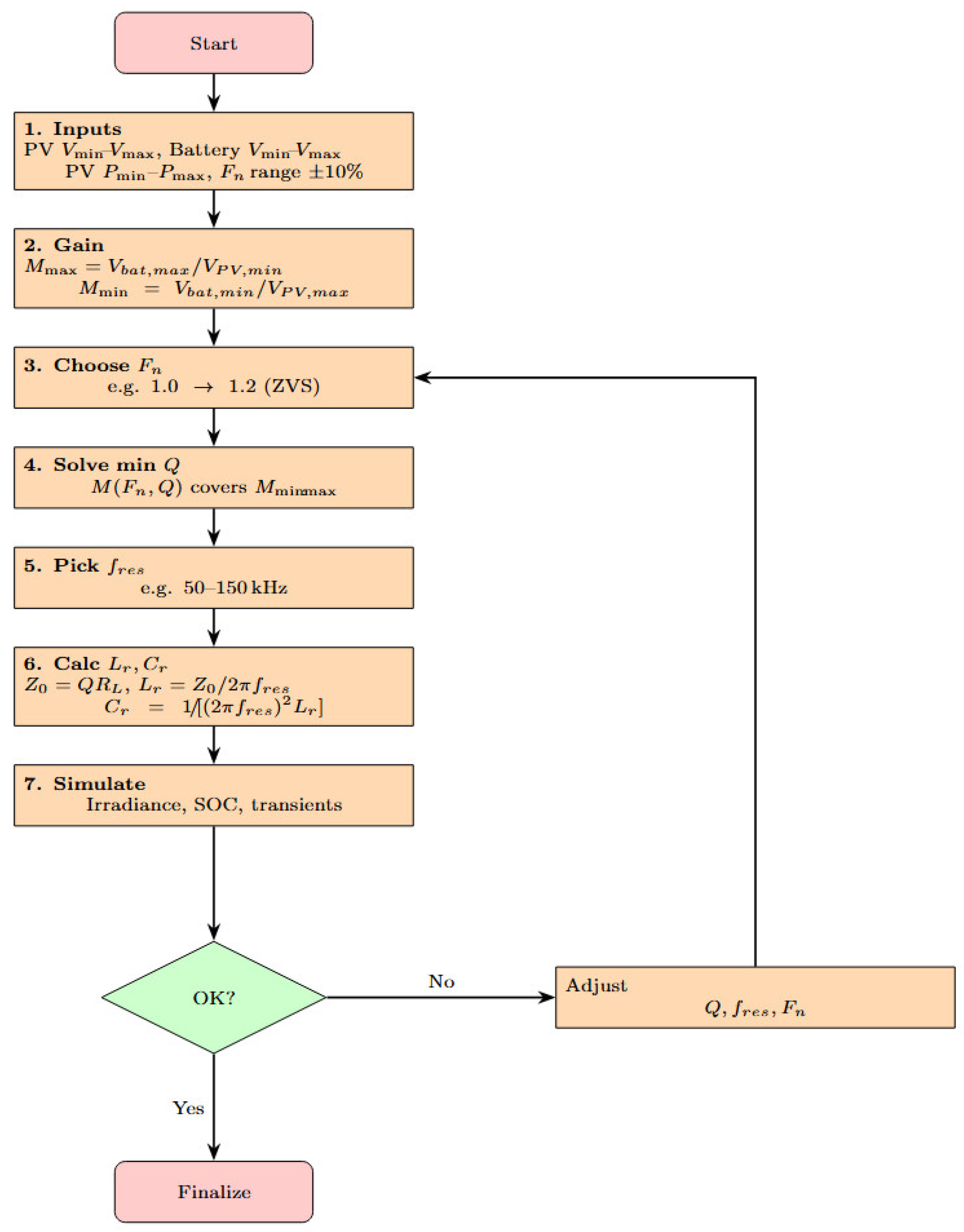
Figure 1c can be used because it has the ability to step down to less than half, operating very close to the resonant frequency. First, the battery and PV voltages and the power range must be known. Then, the maximum and minimum voltage gains can be calculated. After that, the operating frequency range can be defined as a normalized value relative to the resonant frequency. By knowing what frequency range is acceptable for control, the minimum quality factor must be determined to include the full range of the voltage gain. This means that, at the minimum-Q curve, the maximum and minimum voltage gains must be achieved within the allowable frequency range. If this is achieved in the minimum-Q curve, it will naturally be achieved in the higher-Q curve as the frequency versus voltage gain change is sharper. After defining the minimum quality factor and the resonant frequency, the resonant tank parameters can be found directly. A flow chart for a systematic procedure to design the parameters of the proposed series resonant converter is shown in
Figure 9.
3. Justification and Formulation of Extremum-Seeking Control for Series Resonant Converters
The suitability of ESC for PFM converters such as resonant converters arises from the fact that their output power exhibits a smooth, unimodal dependence on switching frequency. This is supported by first harmonic approximation (FHA) analysis, which models the resonant tank as a frequency-dependent impedance. This characteristic aligns well with the assumptions required for ESC to converge to the true extremum. Furthermore, the derivation in this paper establishes a specific formulation of ESC where the switching frequency serves as the control input and the PV power as the output to be maximized. The resulting system should satisfy the ESC design conditions: time scale separation, a smooth input–output map, and unimodal behavior.
Controlling resonant converters presents unique challenges due to their highly nonlinear and frequency-dependent behavior. Unlike traditional PWM converters, resonant converters exhibit a complex relationship between switching frequency and output voltage or current, which is strongly influenced by the load and the resonant tank parameters. This nonlinearity complicates the development of accurate small-signal models, particularly under variable operating conditions such as changing load or input voltage. Furthermore, the resonant gain characteristics can shift significantly due to component tolerances and parasitic elements, making precise analytical control design difficult. Traditional linear control techniques often require extensive system identification and parameter tuning, which may not be robust to environmental variations or aging effects. Extremum-seeking control (ESC) offers an effective solution to these challenges by providing a model-free optimization approach. Instead of relying on a detailed mathematical model, ESC continuously perturbs the system input, such as the switching frequency, and observes the output response to iteratively locate the optimal operating point, typically the maximum power point (MPP) in PV applications. This real-time adaptation enables ESC to handle the inherent nonlinearities and uncertainties of resonant converters, ensuring stable and efficient operation without the need for complex modeling or controller redesign, even as system parameters change over time. Moreover, ESC is particularly suitable for PV maximum power point tracking (MPPT) because the PV power–voltage curve is generally smooth and unimodal under uniform irradiance, forming a static map that does not exhibit fast dynamics. The static and smooth nature of the PV characteristic curve ensures that the ESC algorithm can reliably and efficiently converge to the true maximum power point without being misled by transient disturbances, which makes it an ideal control strategy for the combined PV–resonant converter system. A general extremum-seeking control (ESC) system is formulated based on the principle of real-time optimization through periodic perturbation and gradient estimation. The core idea of ESC involves applying a small sinusoidal perturbation to the system input, measuring the system output response, and demodulating this response to estimate the gradient of the output with respect to the input. Specifically, if the control input is denoted by
and the system output by
, ESC perturbs the input as
where
is the slowly varying nominal input,
is the perturbation amplitude, and
is the perturbation frequency. The output
is then multiplied by
and passed through a low-pass filter to extract an estimate of the gradient
. This estimate is used to update
through an integrator and drive the system toward the extremum of the input–output map. The general formulation of ESC relies on the assumptions that the system output is smooth, has a unique extremum, and that the dynamics of the system are slow relative to the perturbation frequency, allowing separation of fast and slow dynamics, and ensuring convergence.
While ESC has been extensively applied in areas such as chemical process optimization, motor control, and photovoltaic (PV) maximum power point tracking (MPPT), to the best of the authors’ knowledge, there has been little or no application of ESC specifically designed for the control of resonant converters. This is a noteworthy gap because resonant converters present complex and highly nonlinear input–output relationships that conventional control techniques struggle to manage without detailed modeling. Furthermore, the operating point of resonant converters is primarily determined by the switching frequency, which makes them inherently suitable for ESC application, where the switching frequency can serve as the control input.
To formulate the ESC specifically for resonant converters in PV charging applications, the switching frequency is chosen as the perturbable control variable. The system output is the PV power , which depends on through the resonant converter’s transfer function and the PV array’s voltage–current characteristics. The control law is constructed by superimposing a small sinusoidal dither onto the switching frequency, measuring the PV power output, demodulating the power signal with the same sinusoidal reference, and integrating the resulting gradient estimate to update the nominal switching frequency.
First, the switching frequency is perturbed by adding a small sinusoidal dither around the nominal value to probe the system’s response.
The PV power is then locally approximated near the maximum power point as a quadratic function of the switching frequency, assuming a unique extremum.
The estimate of the error of the switching frequency can be denoted as
Substituting it into the power expression yields
And this can be re-written as
This shows that the power to frequency response has three main components: the DC component, the fundamental component, and the double-frequency component. A high-pass filter then removes the DC component and slow variations in the power signal and isolates the response that resulted from the perturbation. After removing the DC component, the remaining part is demodulated by multiplying it by
.
And after derivation and arrangement of terms, the error becomes
It can be seen that the non-oscillatory term in the error is the first term, and it correlates directly to the gradient estimation. It can then be easily extracted by a low-pass filter, providing an estimate of the gradient.
Finally, the nominal switching frequency is updated in the negative gradient direction to iteratively move toward the maximum power point.
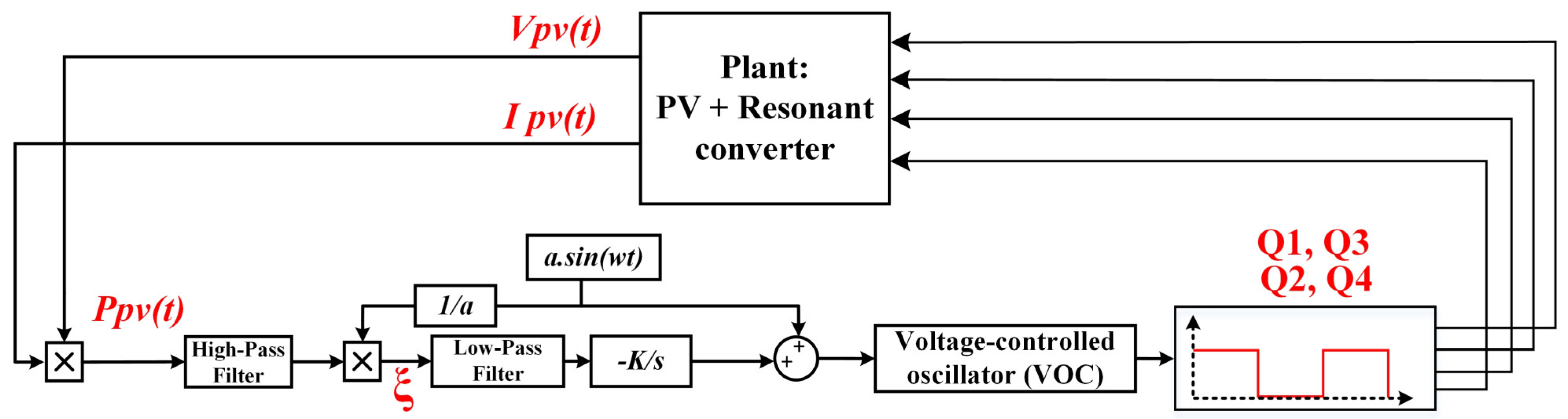
Through this formulation, the ESC algorithm adaptively drives the converter’s switching frequency toward the value that maximizes PV power output, ensuring maximum power point tracking without requiring a precise model of the resonant converter or the PV array. The overall control structure of the system is shown in
Figure 10. The instantaneous power of the PV panel will be monitored through measuring the voltage and current of the PV. The ESC algorithm then generates the voltage control signal that will set the required frequency. The frequency is generated by a standard voltage controlled oscillator circuit with a fixed 0.5 duty cycle. The signal is then sent to the active switches in a complementary manner.
The perturbation frequency
should be chosen to be fast enough to produce a gradient change in the system but also slow enough to appear semi-static to the system dynamics.
The perturbation amplitude
is directly related to the frequency range of the resonant converter, so it should be small enough to avoid causing significant changes in frequency, especially within the narrowest gain–bandwidth range which happens at the maximum expected quality factor curve.
where
N is the number of allowable steps within the narrowest gain–bandwidth range. The adaptation gain
affects the rate of convergence of the system and how quickly it reaches the optimum. It should be chosen to ensure sufficiently fast convergence, but not so high as to cause oscillations and severe changes in the system dynamics, i.e., the switching frequency. In the case of MPPT, a convergence rate in the range of a few seconds is acceptable given the nature of the PV system.
4. Simulation and Results
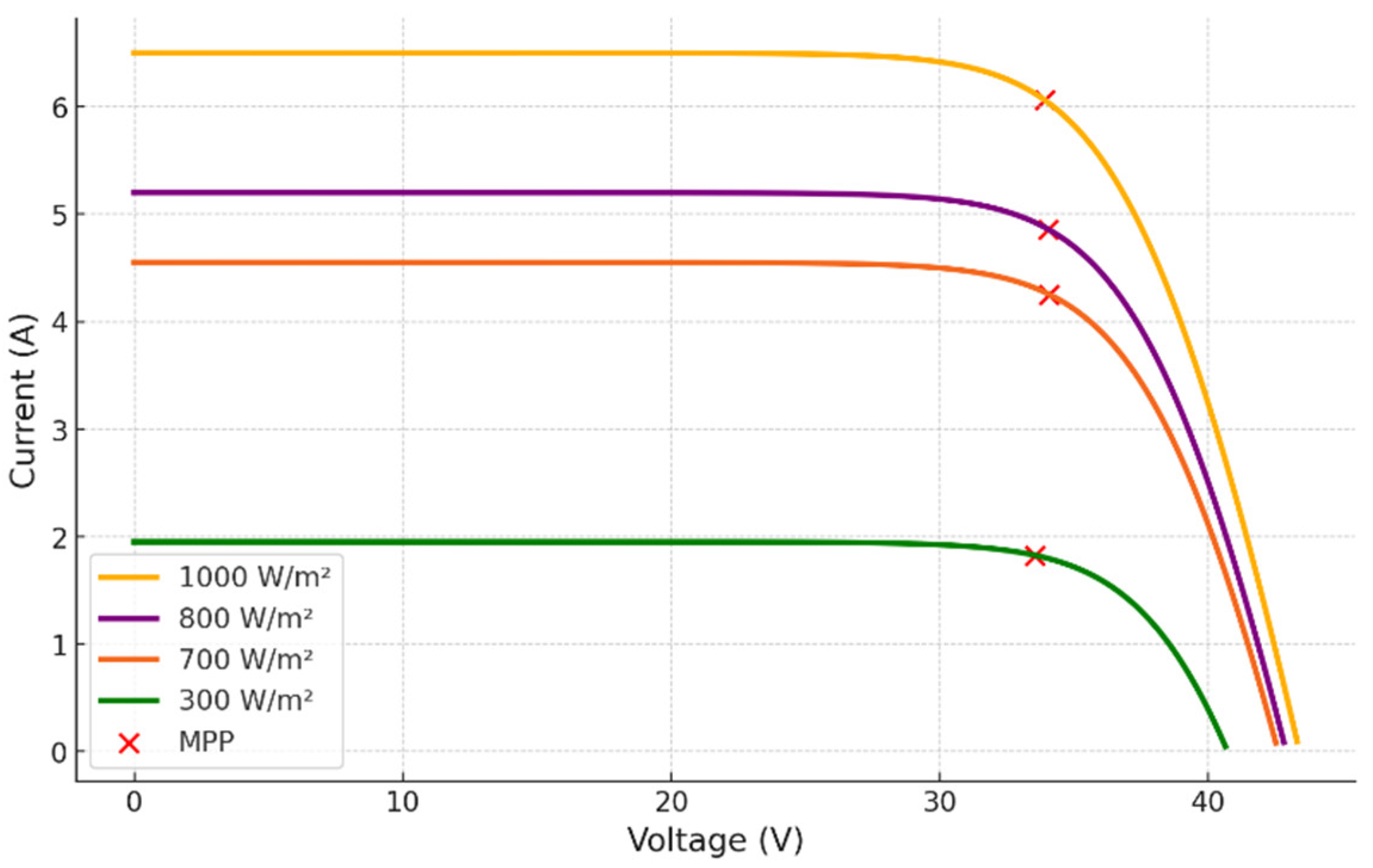
In this section, a simulation study using PSIM software (2024.1) is presented to validate both the design procedure of the series resonant converter and the proposed ESC algorithm formulated for the series resonant converter. The characteristics of the PV panel shown in
Figure 11 are the ones used for this design case. The PV panel has I_V curves under different irradiance levels, as shown in
Figure 11 and
Table 1.
The battery was represented with a simple model that consisted of a voltage source and a series resistance, and the voltage source was changed for different simulation cases. For a 24 V battery, a minimum voltage of 24 V was considered and a series resistor of 0.05 Ω was included. A maximum voltage of 28 V could be considered for simulating a high state of charge (SOC). These values can be adjusted for specific battery specifications, but for a 24 V battery pack, they are typically representative. The design procedure in
Figure 9 can now be applied using the system parameters shown in
Table 2 and
Table 3.
For the given PV parameters and a battery voltage of 26 V, the expected operating points of the designed system when tracking maximum power are shown in
Figure 12. It can be seen that the change in the switching frequency required to match the desired voltage gain is well within the specified range of 20%, and the required voltage gain is also achievable.
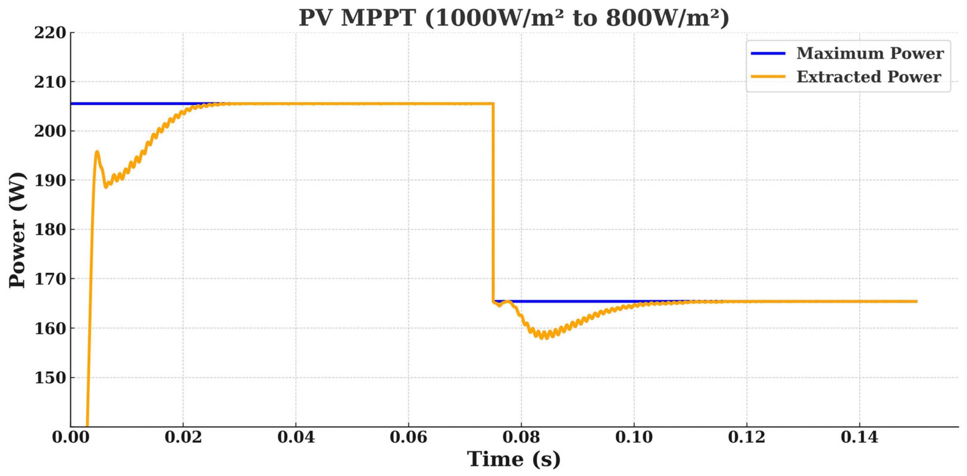
These parameters can now be simulated, and different scenarios can be implemented to validate the operation of the converter and the algorithm. The first case shows the system at a 1000
irradiance level, and the battery voltage is at its minimum level of 26 V. It can be seen in
Figure 13 that the converter is successfully tracking and extracting the maximum available power with stable output. The irradiance level is then stepped down to 800
at 0.075 s, and the converter responds appropriately, continuing to track and extract the new available power, which is around 165 W.
The converter in this case is operating at a frequency higher than the resonant frequency and zero-voltage switching is achieved, as seen in
Figure 14.
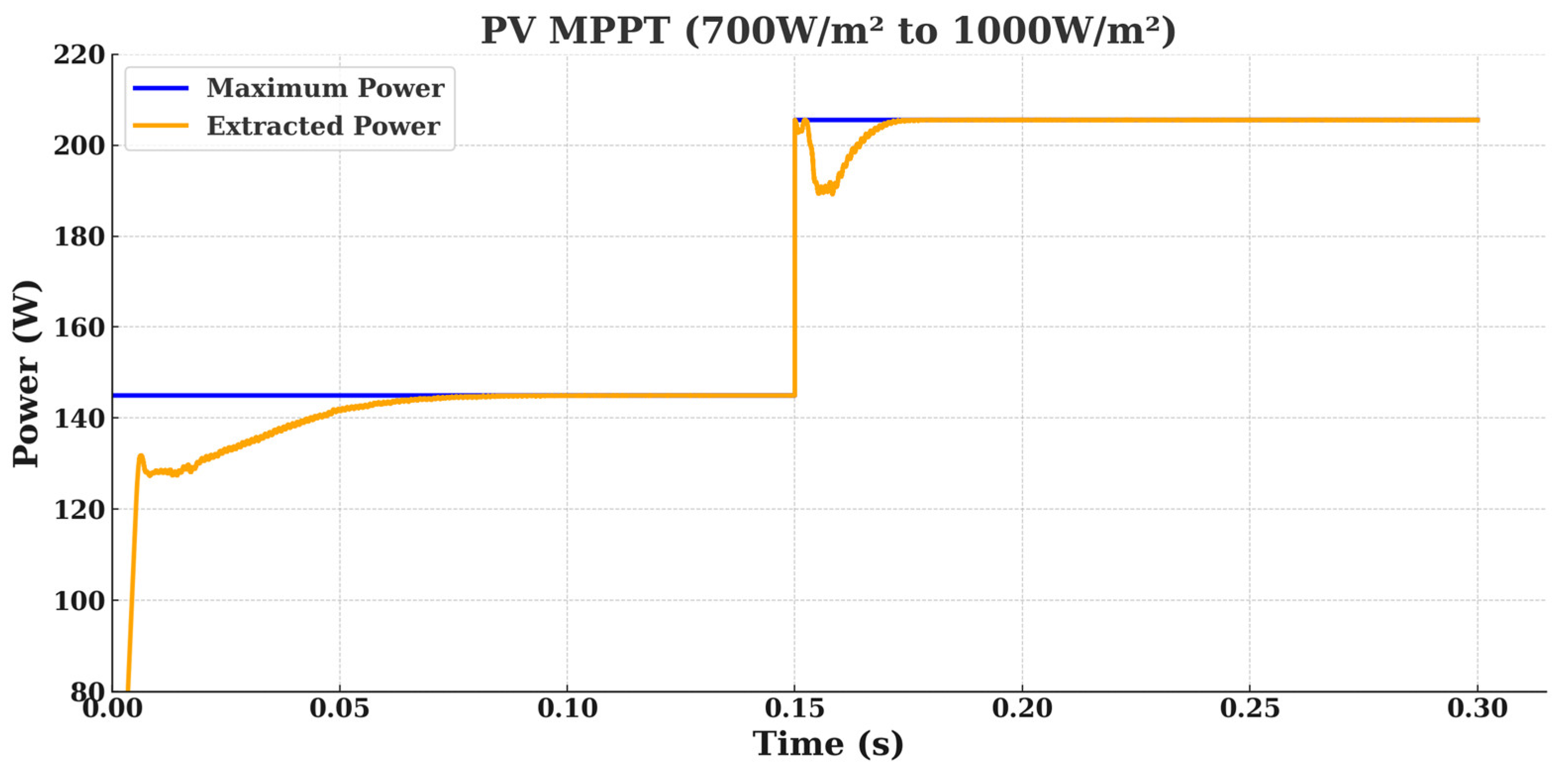
The next case (
Figure 15) shows a starting irradiance level of 700
and an MPP of 142 W, where the resonant converter is tracking well. Then, at 0.15 s the irradiance level is stepped up to 1000
. It can be seen that the converter is following the reference in both step-up and step-down scenarios.
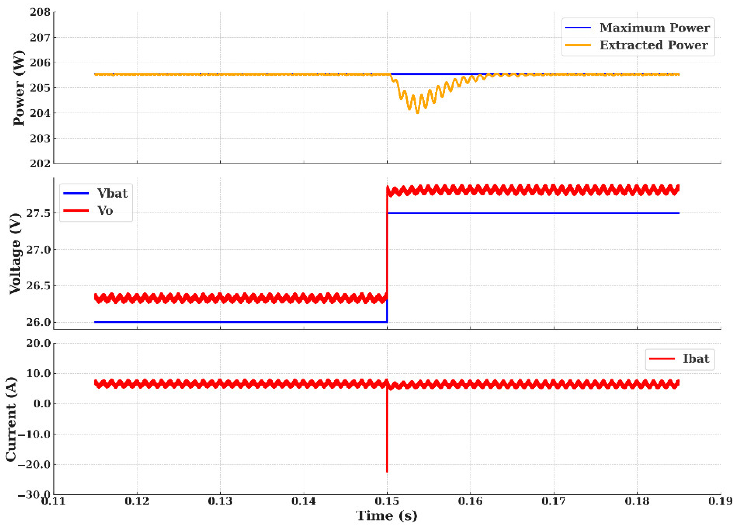
In addition to stepping the irradiance, a step increase to the battery voltage was introduced to check whether the converter would track the MPPT under load-side variations. The battery voltage was stepped from 26 to 27.5 volts and the converter exhibited a quick adjustment in output voltage to maintain maximum power at the same level.
Figure 16 shows the step increase at 0.15 s.
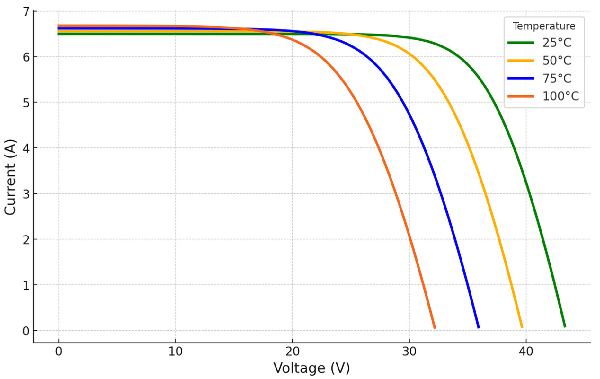
In addition to the previous results, a disturbance in the temperature of the PV panel was introduced to test the effectiveness of the proposed algorithm and converter in MPPT under varying conditions. The PV panel’s I-V characteristics as functions of temperature are shown in
Figure 17.
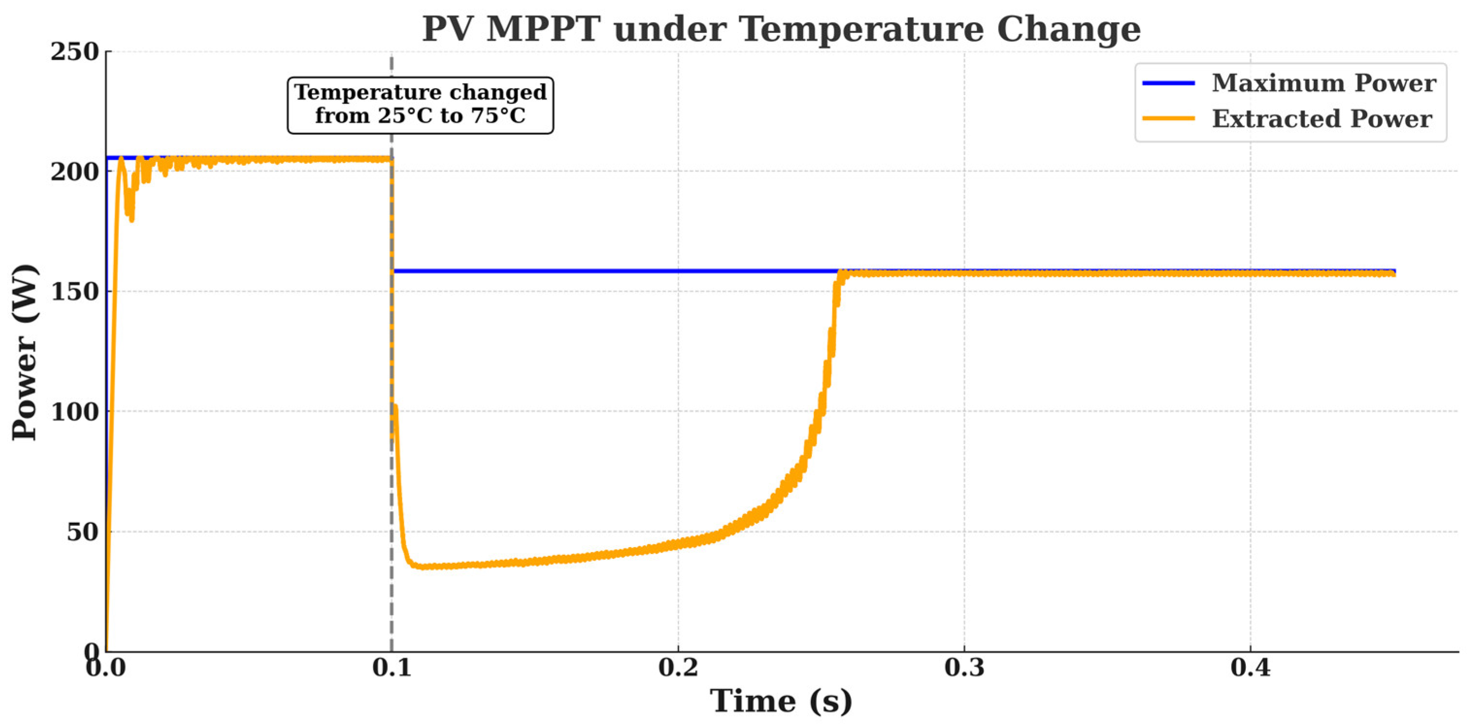
It can be seen that the voltage change is more severe with temperature than with irradiance. Therefore, as long as this voltage variation is included in the design procedure mentioned earlier, the MPPT algorithm should be able to track it with no issue. The next simulation case (
Figure 18) shows a step increase in temperature from 25 to 75 degrees and the corresponding MPPT.
This simulation shows that the controller can handle a severe temperature increase from 25 °C to 75 °C. It quickly adjusts and continues to track the new maximum power point smoothly and without oscillations.
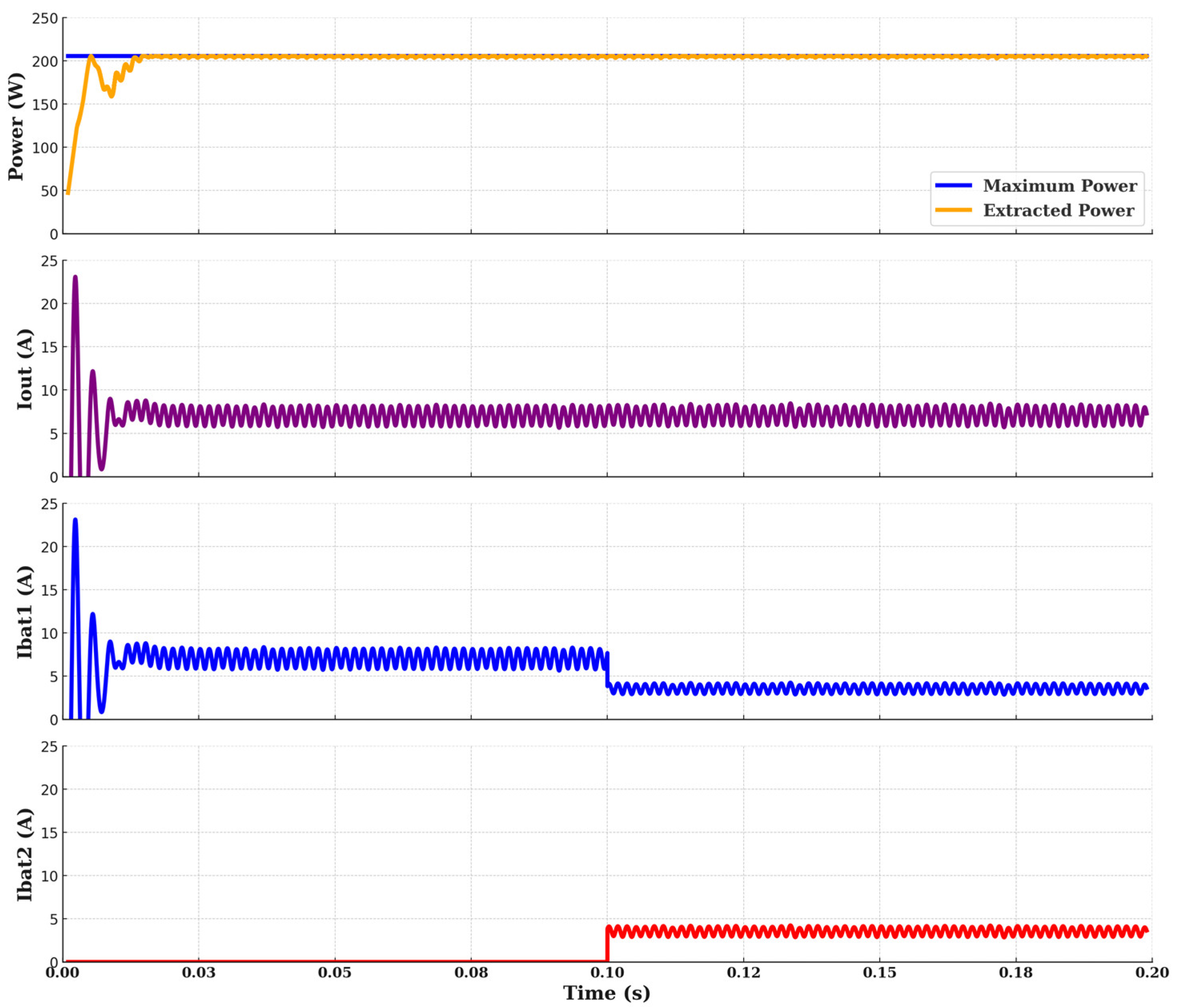
Another simulation was performed, in which a second battery was connected in parallel with the existing one at 0.1 s. As shown in
Figure 19, the converter continued to track the maximum power point effectively. The output current remained stable despite the change in total load impedance, and the current naturally redistributed between the two batteries as expected, which confirms that the ESC algorithm can adapt to sudden changes in load configuration without a loss of performance.
5. Discussion
The proposed resonant converter with ESC-based control is inherently capable of operating across a range of voltages and load impedances, enabling compatibility with typical battery voltage ranges encountered in lithium-ion and lead–acid battery systems. However, as ESC is focused on maximizing power extraction, it does not enforce the Constant Current or Constant Voltage charging profiles required for battery health and safety. These profiles must be ensured via integration with a battery management system (BMS), or through an outer loop, supervising and limiting voltage and current levels. Moreover, the converter can adapt to changes in load impedance, such as the connection or disconnection of parallel battery units. Such events may cause shifts in the converter’s operating point, but the ESC algorithm dynamically adjusts the switching frequency to track the new maximum power point.
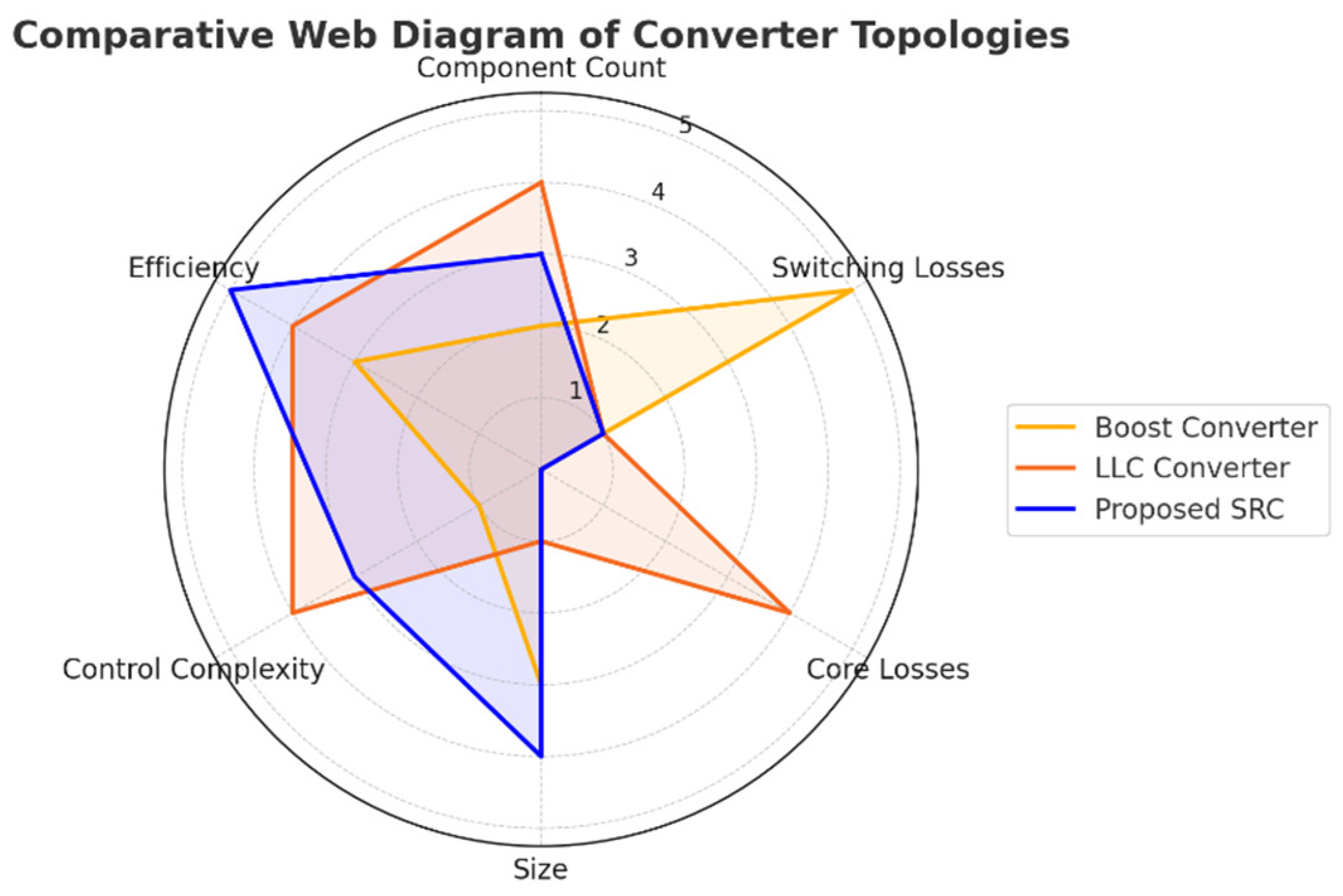
Robustness under temperature and irradiance variations is critical in PV systems and has been validated under both temperature and irradiance disturbances. The simulation results demonstrate that the proposed system tracks the maximum power point with a less than 3% steady-state error and a dynamic response time of under 50 ms following irradiance changes, and less than 150 ms after temperature changes. As a model-free algorithm, ESC adapts well to these conditions. Compared to conventional MPPT methods, ESC offers advantages in systems where linearization is difficult, such as PFM converters. A general comparative radar diagram is presented in
Figure 20, highlighting the key differences between the proposed SRC converter and other topologies for MPPT battery charging applications.
In addition,
Table 4 provides a quantitative comparison that highlights the system’s unique benefits and implementation simplicity compared with other topologies reported in the literature.
The ESC algorithm demonstrated very good tracking of the maximum power point in the simulation results. One of its main advantages is that it avoids voltage overshoot because of its smooth and gradual response. This makes it especially suitable for PV applications where stable voltage is essential. Another benefit is that all components of the ESC algorithm, such as the low-pass filter, high-pass filter, and integrator, operate in continuous time, which gives it the flexibility to be used in either analog or digital form, unlike many other MPPT methods that rely solely on digital control.
Table 5 presents a comparison of the ESC method with other MPPT techniques based on four key factors: the computational effort, cost of implementation, need for a system model, and suitability for continuous-time (analog) implementation.