1. Introduction
As critical components in rotating machinery, the accurate prediction of fatigue life for cylindrical roller bearings is essential for ensuring equipment reliability. Thus, predicting and extending bearing service life remains a central challenge in bearing design and application [
1,
2,
3]. The classical Lundberg–Palmgren (L-P) theory [
4,
5] establishes a statistical framework for rolling bearing life calculation. However, to achieve higher accuracies, more precise determination of internal contact load distributions within bearings is required. In recent years, numerous scholars have proposed various related models.
Jones [
6] developed a quasi-static analysis model for rolling bearings by accounting for the elastic deformation of shafts and supporting structures, as well as centrifugal and gyroscopic loads on rollers under high-speed operation. Creţu [
7] revealed the roles of roller geometry, operating clearance, misalignment angle, and working loads in shaping contact pressure distributions between rollers and their corresponding inner/outer ring. Liu et al. [
8] established a dynamic model for high-speed-train bearing–rotor systems under variable-speed conditions, incorporating unbalanced excitation caused by rotor mass eccentricity. Experimental validation on bearings with outer and inner race faults under diverse operating conditions confirmed the model’s effectiveness. Li et al. [
9] proposed a novel damage evolution equation based on octahedral shear stress amplitude, enabling the numerical simulation of crack initiation, propagation, and spalling. They systematically explored the correlation between contact stress and fatigue damage, along with its impact on material fatigue life. Zhang et al. [
10], guided by race control theory [
11], constructed an improved quasi-static model by analyzing the contact characteristics between balls and races, thereby elucidating the relationship between preload and bearing fatigue life. However, the presence of lubricant films significantly alters contact zone stresses and fatigue failure mechanisms. Existing quasi-static models often neglect lubrication effects, leading to deviations in life predictions.
For line contact elastohydrodynamic lubrication problems, solutions typically involve coupled Reynolds, film thickness, Hertzian contact pressure, squeeze, and dynamic load equations. Grubin [
12] and Dowson [
13] laid the foundation for numerical solutions, with subsequent scholars [
14,
15,
16] refining elastohydrodynamic lubrication models to address non-Newtonian fluids, surface roughness, and thermal effects. Recent studies [
17,
18,
19] predominantly employ the multigrid method for solving elastohydrodynamic lubrication problems. Since its foundational work by Fedorenko [
20], the multigrid method has evolved into a core technique for solving large-scale partial differential equations. The finite difference method, capitalizing on its regular grid structure, intuitive discretization approach, and inherent compatibility with the multigrid transfer process, functions as the principal platform for the initial application and advancement of multigrid techniques. Within the framework of the finite difference method, the multigrid method matures rapidly, extending its scope from linear elliptic partial differential equations to encompass strongly nonlinear systems, parabolic problems, and adaptive mesh refinement. It now finds extensive application across computational physics and engineering disciplines [
21,
22,
23]. Compared with alternative iterative computational approaches, the multigrid method demonstrates significant advantages in computational efficiency, solution accuracy, and problem applicability, particularly in the analysis of lubrication problems involving complex contact conditions.
This study proposes a fatigue life prediction method for cylindrical roller bearings that combines elastohydrodynamic lubrication and quasi-static analysis. First, the isothermal line contact Reynolds equations are solved using the multigrid method to obtain pressure and film thickness distributions. Second, a quasi-static model for cylindrical roller bearings is established based on elastohydrodynamic lubrication theory, enabling the calculation of fatigue life via the modified L-P theory. The effects of load, speed, and viscosity are systematically investigated. Finally, the bearing fatigue life is experimentally validated. Existing research has achieved significant progress in both bearing fatigue life analyses and the solution to elastohydrodynamic lubrication problems. However, most studies have yet to integrate elastohydrodynamic lubrication theory with bearing fatigue life analysis. The contribution of this work lies in optimizing bearing fatigue life analysis methods through the introduction of elastohydrodynamic lubrication theory. It provides a novel computational model for rolling bearing fatigue life, thereby addressing a gap in the existing body of research. Furthermore, the findings can provide a theoretical basis for the design of generator bearings.
2. Quasi-Static Modeling of Cylindrical Roller Bearings Considering Elastohydrodynamic Lubrication
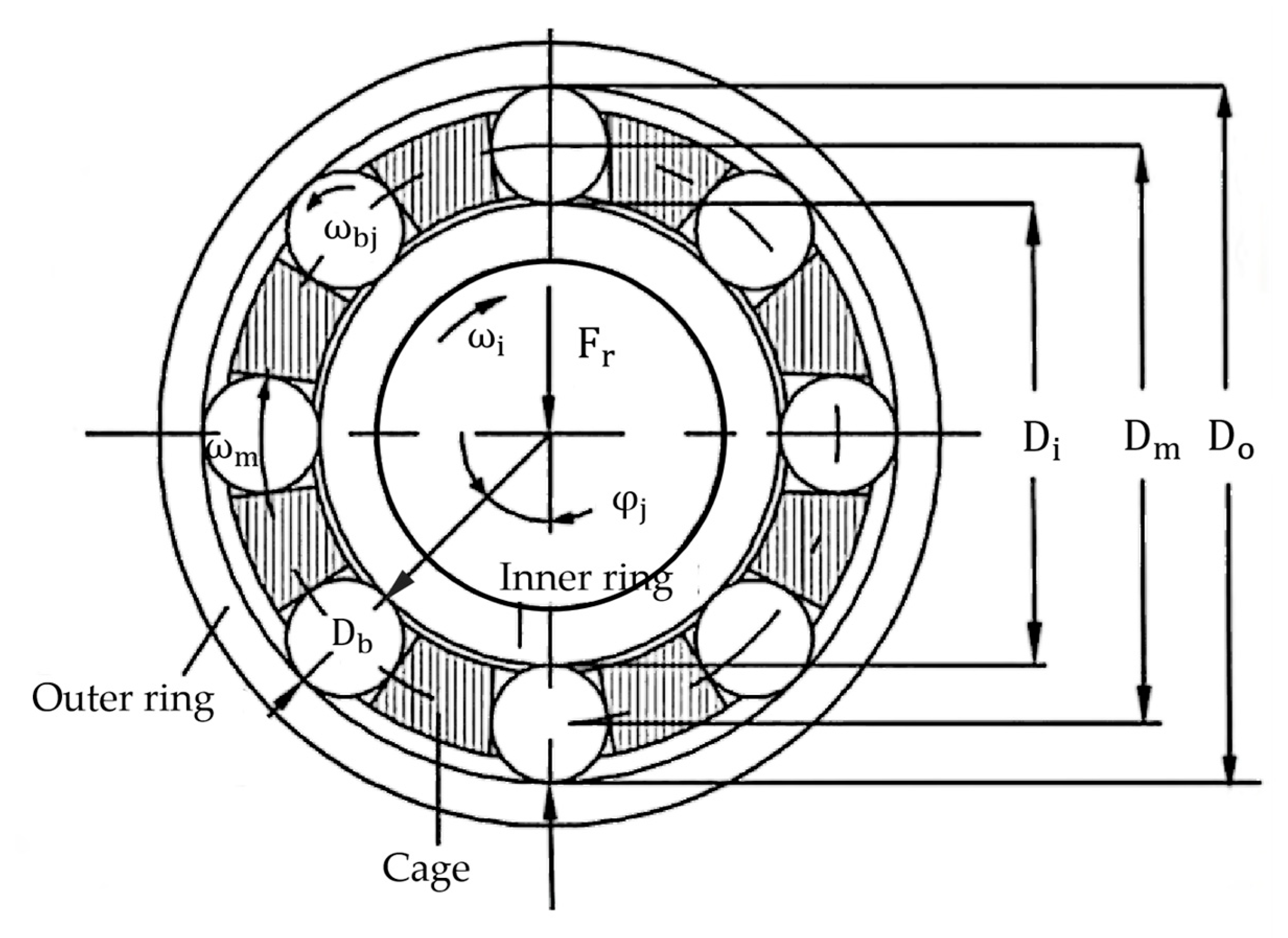
The structure of a cylindrical roller bearing is illustrated in
Figure 1. The key parameters include the roller diameter
, bearing pitch diameter
, outer ring diameter
, inner race diameter
, and the positional angle
of the rollers. Additionally, the angular velocity of the inner race is
, the outer ring remains stationary, the spin angular velocity of each roller is
, and the orbital angular velocity relative to the cage is
.
2.1. Elastohydrodynamic Lubrication Model and Equations for Cylindrical Rollers
Under fully lubricated conditions, the lubricant film separates the rolling elements from the raceways, leading to pressure distributions distinct from Hertzian contact pressure. The Reynolds equation, governing the flow of lubricant between two surfaces, serves as the foundation for hydrodynamic and elastohydrodynamic lubrication theories.
Assuming isothermal Newtonian fluid conditions, the Reynolds equation for finite line contact elastohydrodynamic lubrication between cylindrical rollers and raceways is expressed as follows [
13]:
where
is the lubricant density (kg/m
3); p is the film pressure (Pa);
is the dynamic viscosity (Pa·s);
is the entrainment velocity (m/s); and h is the film thickness (m).
The film thickness equation is given by the following:
In this formula,
can be expressed as follows:
where E is the comprehensive modulus of elasticity (MPa) of the contact surface;
is the combined radius of curvature in the direction of the roll;
is the central membrane thickness; and
are the solution boundaries specified in this study.
The Roelands viscosity formula is as follows:
The Dowson–Higginson formula was adopted:
Under the given load conditions, the pressure distribution p within the roller–raceway contact zone must satisfy the load equilibrium constraint:
where
is the applied load.
2.2. The Geometric Approach Relationship Between Rollers and Races
As shown in
Figure 2, the interaction between rollers and races is derived from the bearing’s geometry. An inertial coordinate system
is established, with analysis confined to the
plane. The outer ring is stationary, while the inner race undergoes translational motion along the
axis.
Let the position vector of the center of the inner ring relative to the center of the coordinate system be
; the position vector of the center of the cylindrical roller relative to the center of the coordinate system be
; and finally, the position vector of the center of the cylindrical roller relative to the center of the inner ring be
:
The geometric approach
between the roller and inner race is expressed as follows:
where
is the bearing pitch diameter; “+” is used when indicating the outer ring of the bearing; and “−” is used when indicating the inner ring of the bearing.
As illustrated in
Figure 3, based on HOUPERT’s conclusions [
24], under the assumption of elastohydrodynamic lubrication conditions for the contact in a roller bearing, the relationship among geometric approach
, elastic deformation
, and film thickness
is as follows:
where
is the dimensionless oil film thickness, with
, where
is the equivalent radius of the rolling direction.
The determination of elastic deformation δ serves as a prerequisite for calculating the contact load Q. Its value can be solved through Equation (9) based on the functional relationship between oil film thickness and the geometric approach quantity. The precise computation of oil film thickness requires the establishment of an elastohydrodynamic lubrication theoretical model and its equations governing the relationship between cylindrical rollers and raceways.
2.3. Establishment of the Quasi-Static Equations
After numerically solving the elastohydrodynamic lubrication equations and obtaining the oil film thickness and pressure distribution, the dimensionless film thickness parameter H is substituted into Equation (9). Through a nonlinear iterative algorithm, the numerical solution of the elastic deformation can then be determined.
The contact characteristics of rolling element bearings satisfy the following three fundamental assumptions: (1) the contacting bodies undergo solely elastic deformation, exhibiting an elastic response that obeys Hooke’s law; (2) the contact surfaces are ideally smooth and subjected exclusively to normal loads, with no tangential friction acting; and (3) the dimensions of the contact zone are significantly smaller than the radii of curvature of the contacting bodies.
Therefore, according to Hertz’s contact theory, the relationship between the contact load and the elastic deformation is as follows [
25]:
where Q is the contact load between the cylindrical roller and the inner ring or the outer ring; k is the load-deformation constant between the cylindrical roller and the inner or outer ring, which is related to the geometric characteristics and the material; n is an exponential, where for point contact, n = 3/2 and, for line contact, n = 10/9;
is the contact elastic variables between the cylindrical roller and the inner or outer ring; and
is the effective length of the rollers.
According to the formula, the contact load between the j-th cylindrical roller and the inner ring, and the contact load between the j-th cylindrical roller and the outer ring are obtained sequentially.
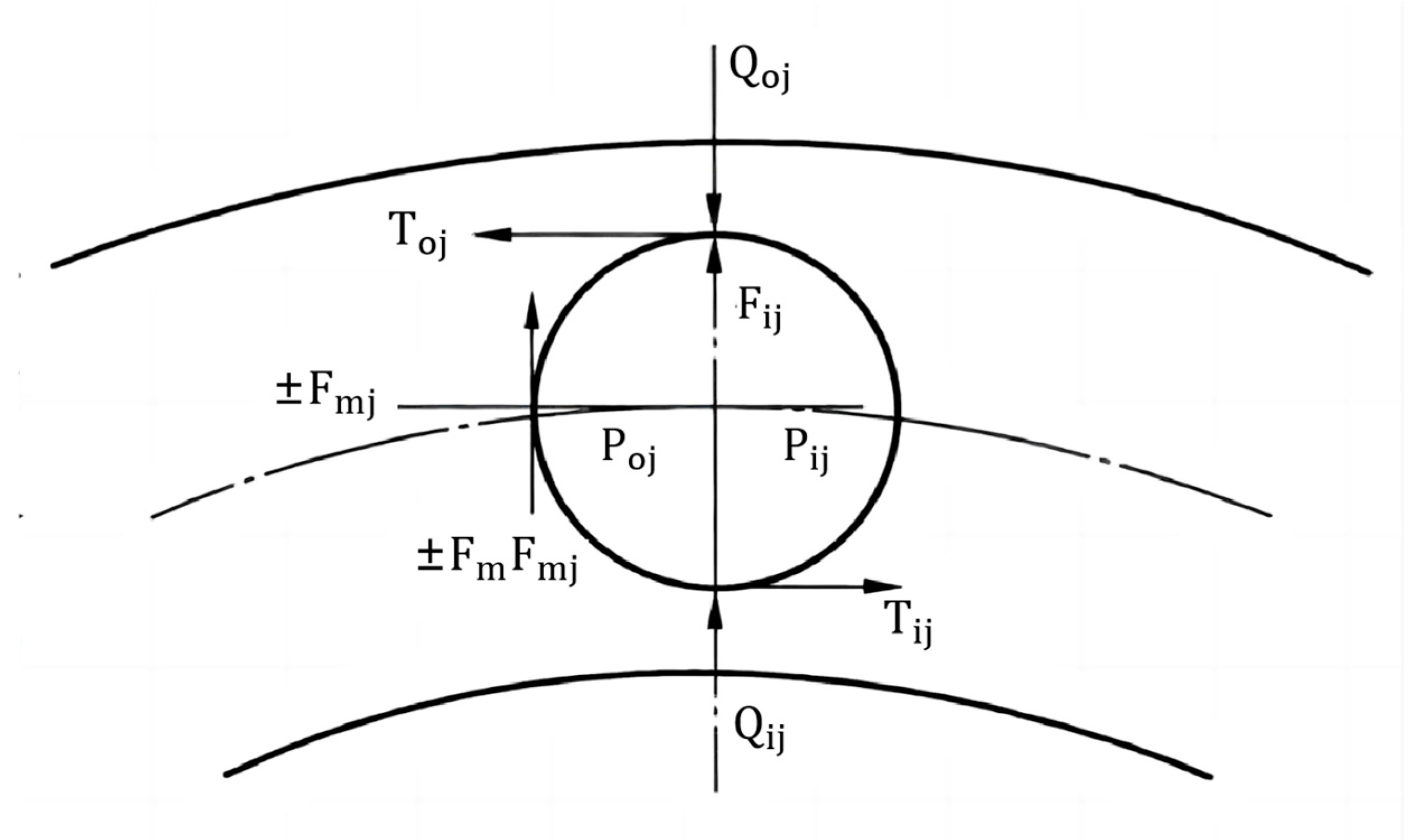
As shown in
Figure 4, three equilibrium equations for cylindrical rollers under the condition of constant rotation can be obtained [
6]:
In this equation, rollers in the unloaded zone are denoted by superscript symbols, while those in the loaded zone are designated with subscript symbols. is the friction between the cage and the cylindrical rollers; are the hydrodynamic pressure acting on the cylindrical rollers through the oil film; are frictional forces acting on a cylindrical roller through the oil film; is the centrifugal force on the cylindrical rollers; and is the normal force between the cage and the cylindrical rollers.
Under the condition of constant rotation, the bearing ring is balanced under the radial load and the cylindrical roller load, and the balance equation of the ring is obtained:
where
is the radial force exerted on the bearing ring;
is the positional angle of each cylindrical roller; and
is the number of cylindrical rollers.
3. Calculation of Bearing Fatigue Life
3.1. Model for Calculating Bearing Fatigue Life
Through the quasi-static model, the contact loads between each cylindrical roller and the bearing inner/outer ring are ultimately determined. Subsequently, the bearing fatigue life can be calculated using the Lundberg–Palmgren life theory.
First, the rated rolling element load for bearing rings is computed as follows [
5]:
In this equation, rollers in the unloaded zone are denoted by superscript symbols, while those in the loaded zone are designated with subscript symbols; considers the edge effect and the reduction coefficient caused by the fact that the load center of the rolling element is not in the middle of the cylindrical roller; for bearing steel materials, is obtained from a large number of experiments, with = 551.3; and = /.
Subsequently, the equivalent rolling element load of the bearing ring is calculated.
The bearings analyzed in this study rotate the inner ring relative to the load direction, and the outer ring of the bearing is stationary relative to the load direction. After a large number of experiments, the equivalent rolling element load is shown to be
where for the rotating inner ring,
= 4, and for non-rotating bezels,
= 9/2.
The formula for calculating the life
of a single bearing ring can be expressed as follows:
where for point contact,
= 3, and for line contact,
= 4. Finally, the formula for calculating the life
of the entire cylindrical roller bearing can be expressed as follows:
3.2. Modified Bearing Fatigue Life Model
The conventional L-P theory-based fatigue life model fails to account for lubricant effects in practical applications. Therefore, the established cylindrical roller bearing fatigue life model is modified by integrating elastohydrodynamic lubrication theory.
A systematic methodology grounded in the I-H theoretical framework is employed to enhance the traditional L-P model’s bearing service life calculation. This improved model incorporates the influences of material properties, lubrication characteristics, lubricant contamination, and fatigue limits. The modified formula is expressed as follows [
3]:
In this formula, is the reliability coefficient when the probability of bearing availability is 0.9 and is the total life modification factor.
The support bearings on the generator’s main shaft primarily operate under elastohydrodynamic lubrication conditions under normal operating conditions [
26]. To determine the total life modification factor, this section requires the integration of the oil film thickness distribution obtained from the elastohydrodynamic lubrication theoretical model to derive the roller–raceway film parameter.
The expression for the film parameter is given as follows:
where
represent the root mean square surface roughness values of the roller and raceway, respectively, with
, and
denotes the arithmetic average surface roughness.
The composite life modification factor
achieves precise bearing life evaluation by incorporating multiple influencing parameters. Its computational model encompasses critical factors including material properties, lubrication conditions, environmental contaminant ingress, fatigue limit stress of contact materials, and operational loading conditions. This study focuses on elucidating the mechanistic effects of lubrication on fatigue life; thus, quantitative calculations of lubrication parameters are prioritized, while other influencing factors are set as fixed parameters. The mathematical expression of this modification factor is formulated as follows:
where
is the viscosity ratio of the lubricant, with
;
is the contamination coefficient, determined as 0.6 from standard cleanliness tables;
is the fatigue limit stress of the contact materials;
are empirical constants (see
Table 1); and
are exponents (see
Table 1).
The values of the constants and exponents in the mathematical expression of the comprehensive life correction coefficient are given below [
25] in
Table 1.
4. Result Calculation and Analysis
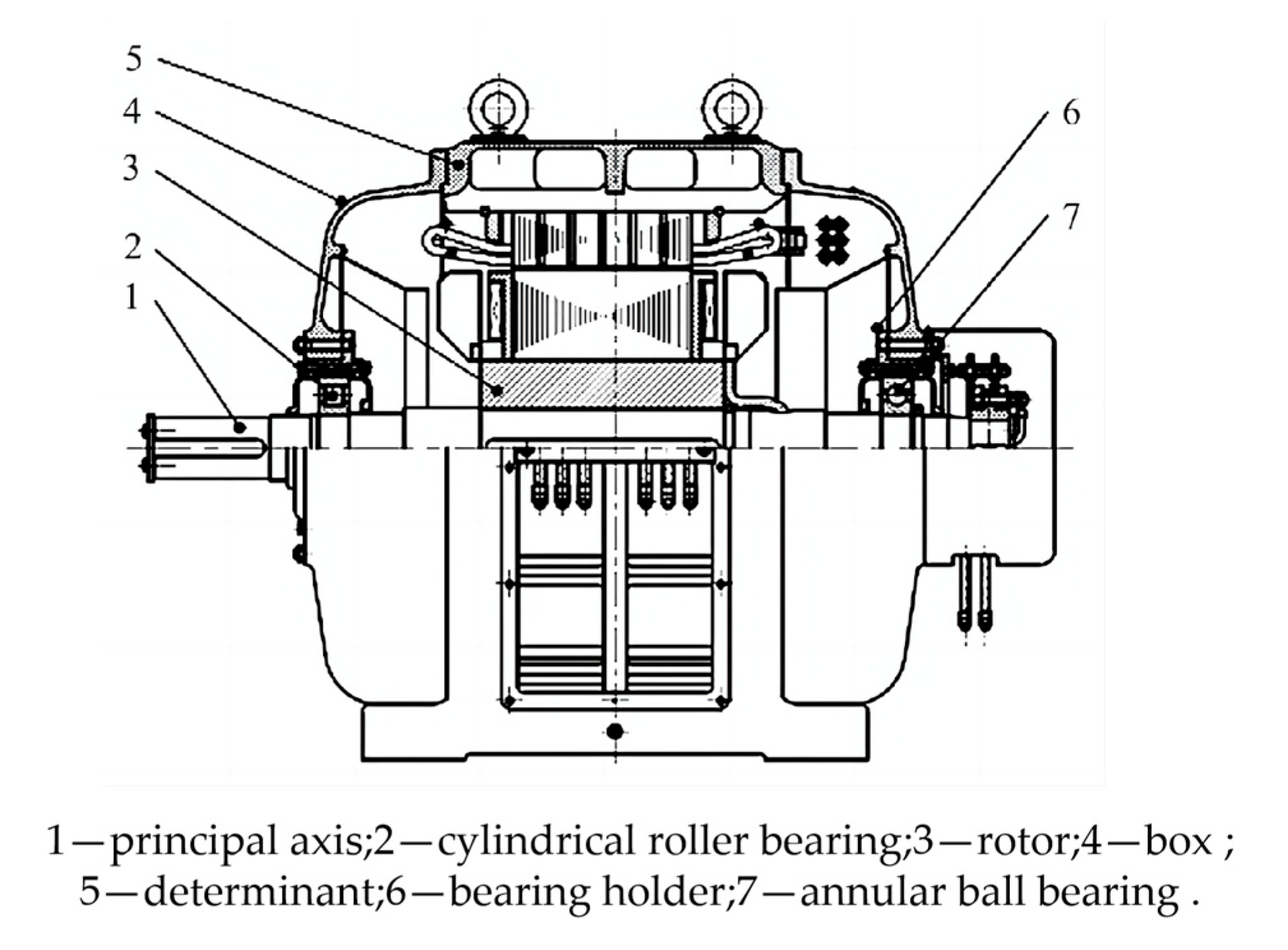
This study mainly analyzes the support bearings on the main shaft of an SFW250-8/850 horizontal hydraulic generator [
27] (located at the left end of the main shaft of the generator). The schematic diagram of the generator structure is shown in
Figure 5.
The relevant parameters for this cylindrical roller bearing are shown in
Table 2.
Taking the cylindrical roller bearing as the research object, the relevant working condition parameters of the bearing in the horizontal hydraulic generator are selected according to GB/T 7894-2023 [
28], and the working condition parameters of the bearing are shown in
Table 3 and
Table 4.
The primary objective of this study is to investigate the influence of elastohydrodynamic lubrication conditions on bearing contact load distribution and ultimately on bearing fatigue life, with the radial clearance set to zero. To rigorously validate the reliability of the proposed theoretical model, the modified reference rating life of cylindrical roller bearings under general loading conditions is calculated according to ISO/TS 16281:2008 [
29,
30,
31]. The computational results from the De Mul’s quasi-static model for cylindrical roller bearings [
32] are compared with those derived from the theoretical model proposed herein.
In De Mul’s quasi-static model for contact load analysis, the mechanism exclusively accounts for rolling element centrifugal forces while neglecting the dynamic lubrication effects between rollers and races. Furthermore, this model confines load generation to geometric approach quantities exceeding zero between the rolling elements and raceways. To simplify the boundary conditions, the analysis is restricted to bearing component motion in the plane under unidirectional pure radial loading.
4.1. Numerical Calculation Method of the Model
Therefore, in order to reduce the number of variables in the equation and eliminate the influence of dimensional differences between the original indexes, it is necessary to dimensionlessly transform the basic equation of Reynolds elastic flow lubrication and its boundary conditions, and the parameters of some dimensionless equations are defined as follows:
Film thickness parameters ; entrainment velocity parameters ; load parameters ; coordinate parameters ; pressure parameters ; lubricant density parameters ; lubricant viscosity parameters ; material parameters ; is the maximum Hertz pressure, where for line contact, ; and is half width of the Hertz contact area, with .
Building upon the quasi-static analysis and integrated with the elastohydrodynamic lubrication model, the specific computational workflow of the developed analytical model is illustrated in
Figure 6. The detailed calculation procedures are as follows:
- (1)
First, input the key geometric parameters of the cylindrical roller bearing, including the roller diameter, quantity, and length and the inner/outer raceway diameters, and define the operational conditions such as radial load. Subsequently, by establishing the initial positions of the races and rollers, solve the geometric approach quantity and entrainment velocity between contacting pairs.
- (2)
Employ the multigrid method to solve the elastohydrodynamic lubrication model for cylindrical rollers. During computation, set grid layers M = 5 with W-cycle iterations, performing all calculations in non-dimensional form. For the roller–raceway lubrication analysis, configure the finest grid layer with 256 nodes and non-dimensional boundary coordinates and . The convergence criterion requires that the relative errors for both pressure and load are less than . Upon satisfying this criterion, the film thickness and pressure distribution are ultimately determined.
- (3)
Substitute the non-dimensional film thickness parameter into Equation (9) to determine the numerical solution of elastic deformation through nonlinear iterative algorithms. Use these results to calculate the final contact load distributions.
- (4)
With the obtained contact loads, sequentially perform numerical solutions for each rolling element sequentially from Equation (11) through Equation (13). If the results satisfy the predefined convergence accuracy thresholds, output the contact load distribution data. For non-convergent cases, refine the roller coordinate position parameters via the bisection method and reintroduce them into the computational loop for iterative optimization.
- (5)
Input the contact loads of all rolling elements into Equation (14) for iterative computation. If the results exceed the allowed convergence tolerance, adjust the race spatial coordinate parameters using the bisection algorithm and restart the computational loop. When the convergence criteria are met, output the optimized contact load datasets and concurrently initiate a quantitative evaluation of bearing fatigue life.
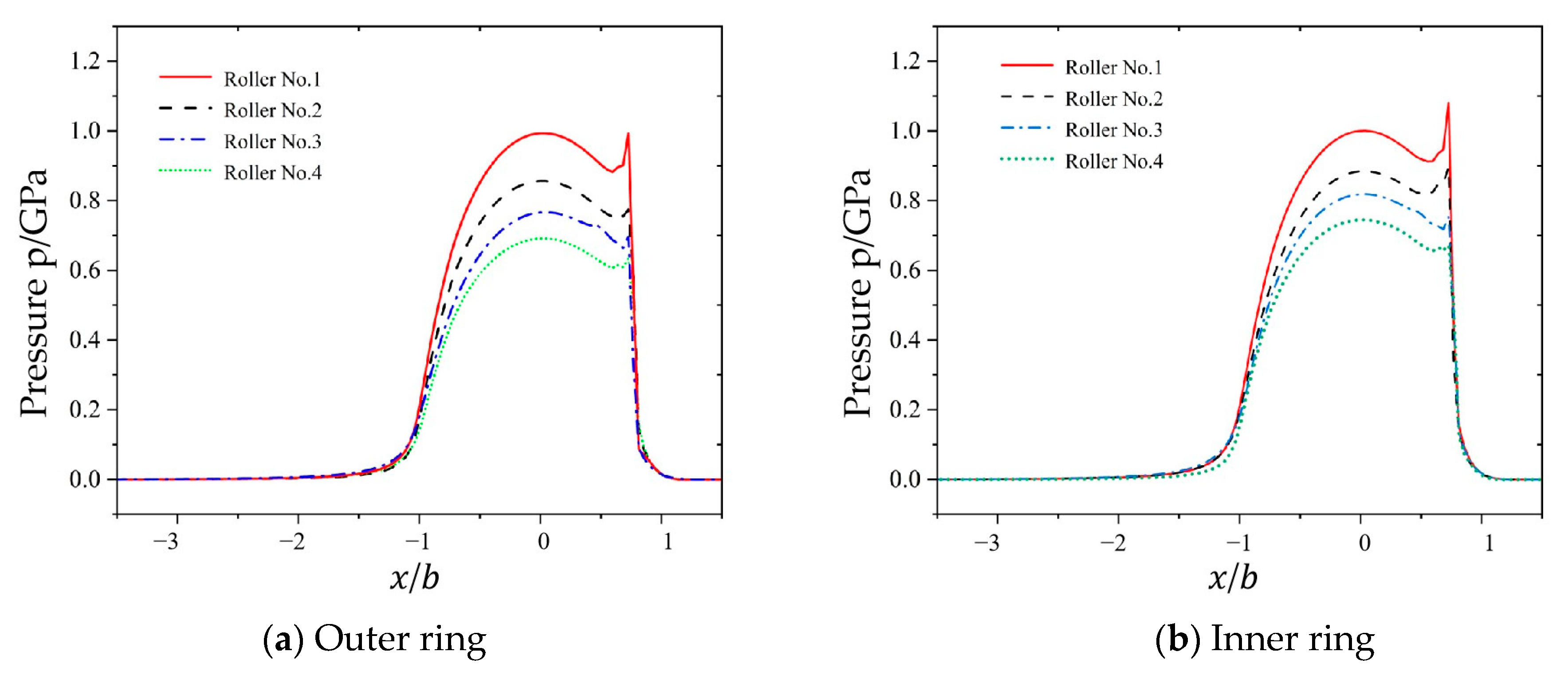
4.2. Analysis of Oil Film Pressure and Thickness for Multiple Rolling Elements
The computational results using the parameters from
Table 2 (cylindrical roller bearing) and
Table 3 (operational conditions) are shown in
Figure 7 and
Figure 8, which illustrate the pressure and film thickness distributions of elastohydrodynamic lubrication under the line contact conditions for each cylindrical roller presented in
Table 3, where the horizontal coordinate
denotes the non-dimensional coordinate along the
direction in the contact zone.
As shown in
Figure 6, the oil film exhibits a horseshoe-shaped profile upon entering the contact zone. As the rollers transition from mesh-in to mesh-out positions, the film thickness gradually decreases with necking phenomena. At the central contact region, the film adopts a parallel configuration.
With an increase in roller number, both the central film thickness and minimum film thickness exhibit a marginally ascending trend, which is fundamentally attributed to the diminishing contact load between the rollers and bearing rings as the numbering increases. Notably, while the load reduction facilitates film thickness growth, the lubricant within the Hertzian contact zone demonstrates viscosity attenuation due to the pressure–viscosity effect, leading to progressive intensification of the curvature in the film thickness decay curve. When considering only the viscosity variation, reduced viscosity inherently decreases the film thickness. Consequently, in the studied case, the diminished lubricant viscosity parameter enhances the decay rates of both the central and minimum film thicknesses, resulting in nonlinear evolutionary characteristics in their distribution profiles.
As shown by the numerical analysis results in
Figure 7, the pressure distribution in the contact zone closely aligns with the Hertzian theoretical pressure distribution. As the roller moves into the engagement phase within the contact zone, the pressure curve exhibits a characteristic pattern of an initial rise, followed by a gradual decrease. This phenomenon occurs because the lubricant entering the contact zone enhances the hydrodynamic effects through extrusion between rollers, leading to pressure elevation. When the roller transitions to the separation phase, the expansion of the lubricant flow space results in pressure reduction. Furthermore, the pressure gradient variations at the inlet and outlet regions of the contact zone tend to flatten.
Additionally, as the contact load progressively decreases from roller No. 1 to No. 4, the overall magnitude of oil film pressure shows a gradual diminution, accompanied by a corresponding decrease in the size of secondary pressure peaks with reducing loads.
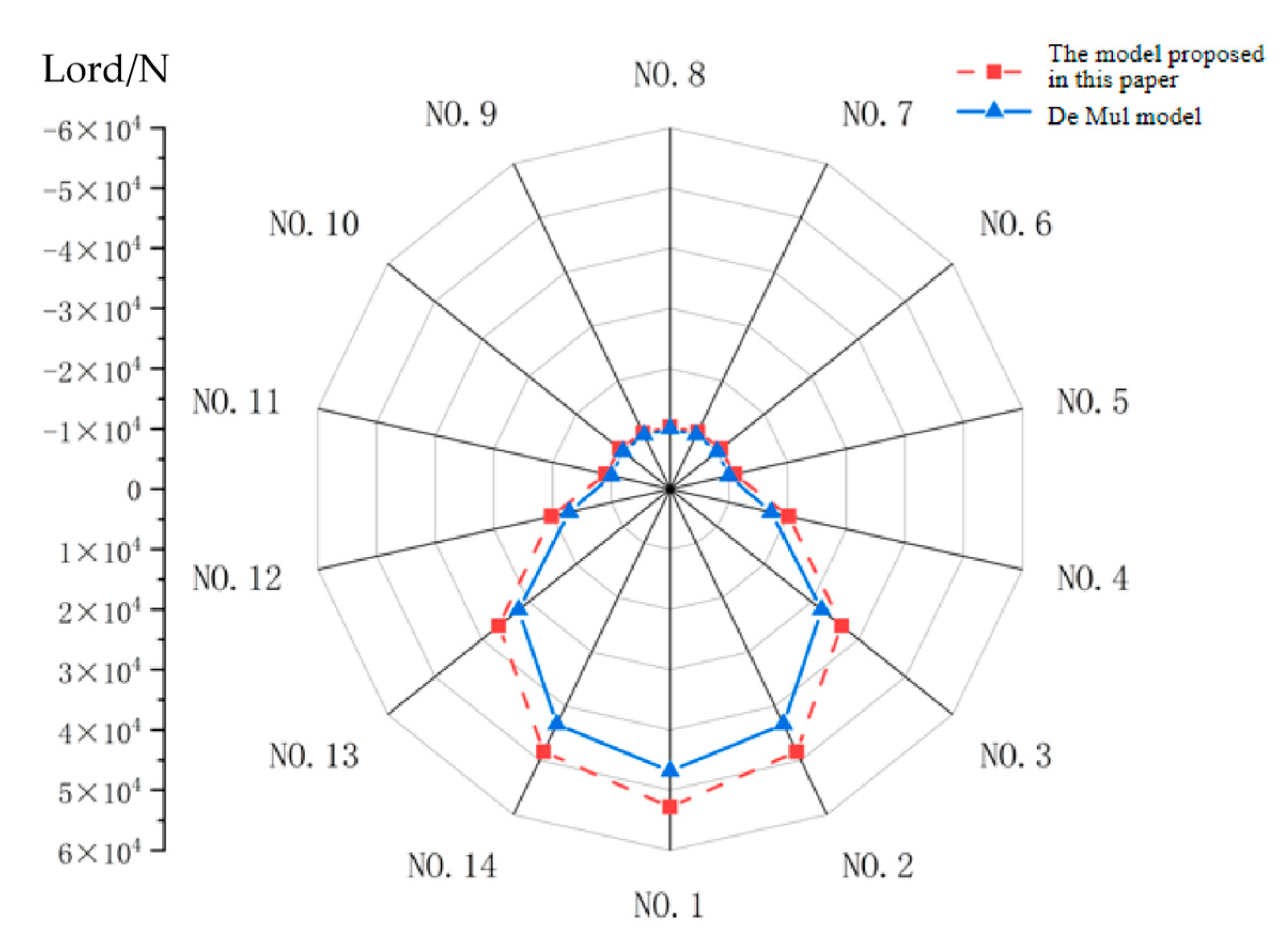
4.3. Influence of Elastohydrodynamic Lubrication Conditions on Contact Load Distribution in Bearings
Figure 9 presents the load distribution between cylindrical rollers and the bearing inner ring under the cylindrical roller bearing parameters specified in
Table 2 and operating conditions listed in
Table 3.
As shown in
Figure 9, calculations using the De Mul model reveal that only roller No. 5 to No. 11 exhibit contact loads with the bearing inner ring. This occurs because the bearing inner ring compresses the lower half of rollers under radial loading, leaving the upper half rollers not in contact with the inner ring and consequently free from elastic deformation. In contrast, the results obtained from the theoretical model proposed in this study demonstrate that, excluding roller No. 1 to No. 4 and No. 12 to No. 13, the remaining rollers maintain minor contact loads with the inner ring. This phenomenon arises because, under lubricated conditions, the formed oil film acts on the rollers even when the geometric approach between the upper rollers and the inner ring remains positive (non-direct contact).
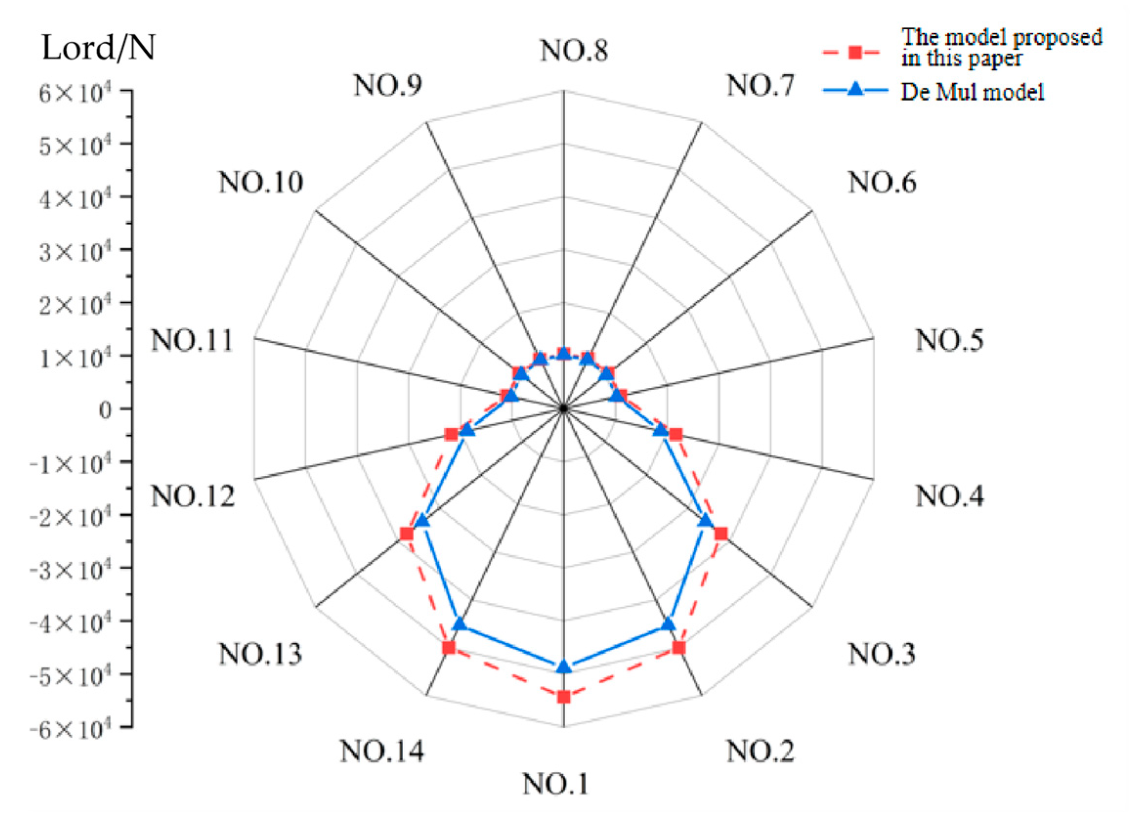
Figure 10 illustrates the load distribution between cylindrical rollers and the bearing outer ring under the cylindrical roller bearing parameters in
Table 2 and operating conditions listed in
Table 3.
As shown in
Figure 10, persistent contact loads exist between cylindrical rollers at all positions and the bearing outer ring. This phenomenon is attributed to centrifugal forces (216.5 N) that press the cylindrical rollers against the outer raceway, thereby maintaining continuous engagement with the bearing outer ring.
Through the incorporation of elastohydrodynamic lubricated conditions between rollers and bearing rings, the theoretical model proposed in this study yields contact loads that marginally exceed those calculated by the De Mul model in overall magnitude.
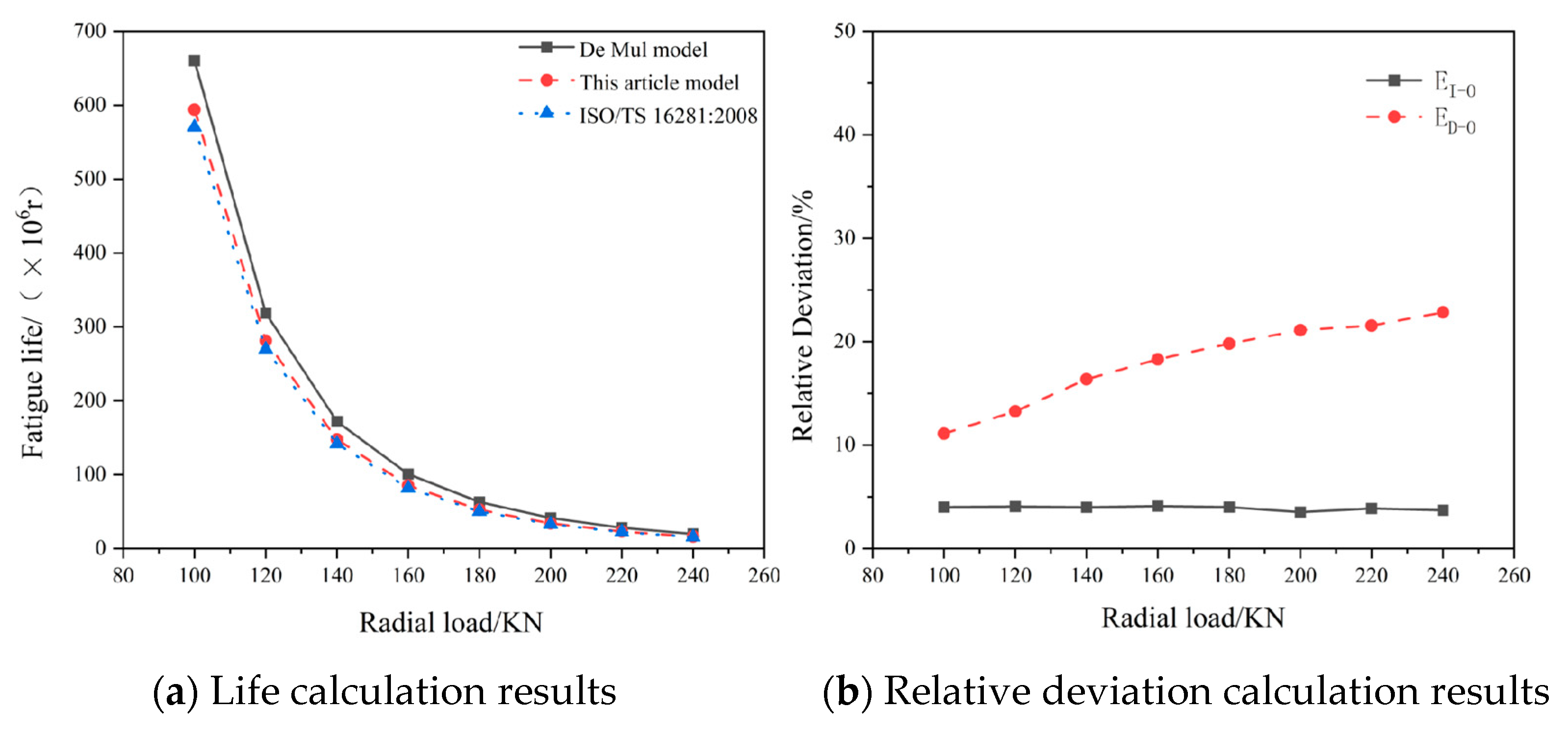
4.4. Effect of Radial Load Variations on Bearing Fatigue Life
Variations in radial loads exert significant impacts on bearing fatigue life. This study calculates bearing lifespan using both the proposed theoretical and De Mul (neglecting lubrication conditions) models, while also determining the modified reference rating life under different load conditions in accordance with ISO/TS 16281:2008.
The influence of different radial loads on bearing fatigue life is presented in
Table 5.
As revealed in
Table 5, (1) bearing fatigue life decreases rapidly with increasing radial loads, and (2) the comparative analysis demonstrates substantial discrepancies between the De Mul model (lubrication-free assumption) and the proposed theoretical model. These differences arise because the consideration of lubrication conditions amplifies roller-bearing ring contact loads, thereby reducing calculated bearing life. Furthermore, when comparing the ISO/TS 16281:2008-calculated modified reference rating life with other models’ results, the ISO-based lifespan is smaller due to additional parameters considered in the standard, including the contamination factor, operational clearance, and misalignment effects.
To further investigate the lubrication state’s impacts on roller bearing system fatigue life, this study computes relative deviations between system lifespans derived from the De Mul model (non-lubricated condition) and the proposed theoretical model, as well as between ISO/TS 16281:2008 calculations and the theoretical model results. The lifespan calculation outcomes and relative deviations are illustrated in
Figure 11.
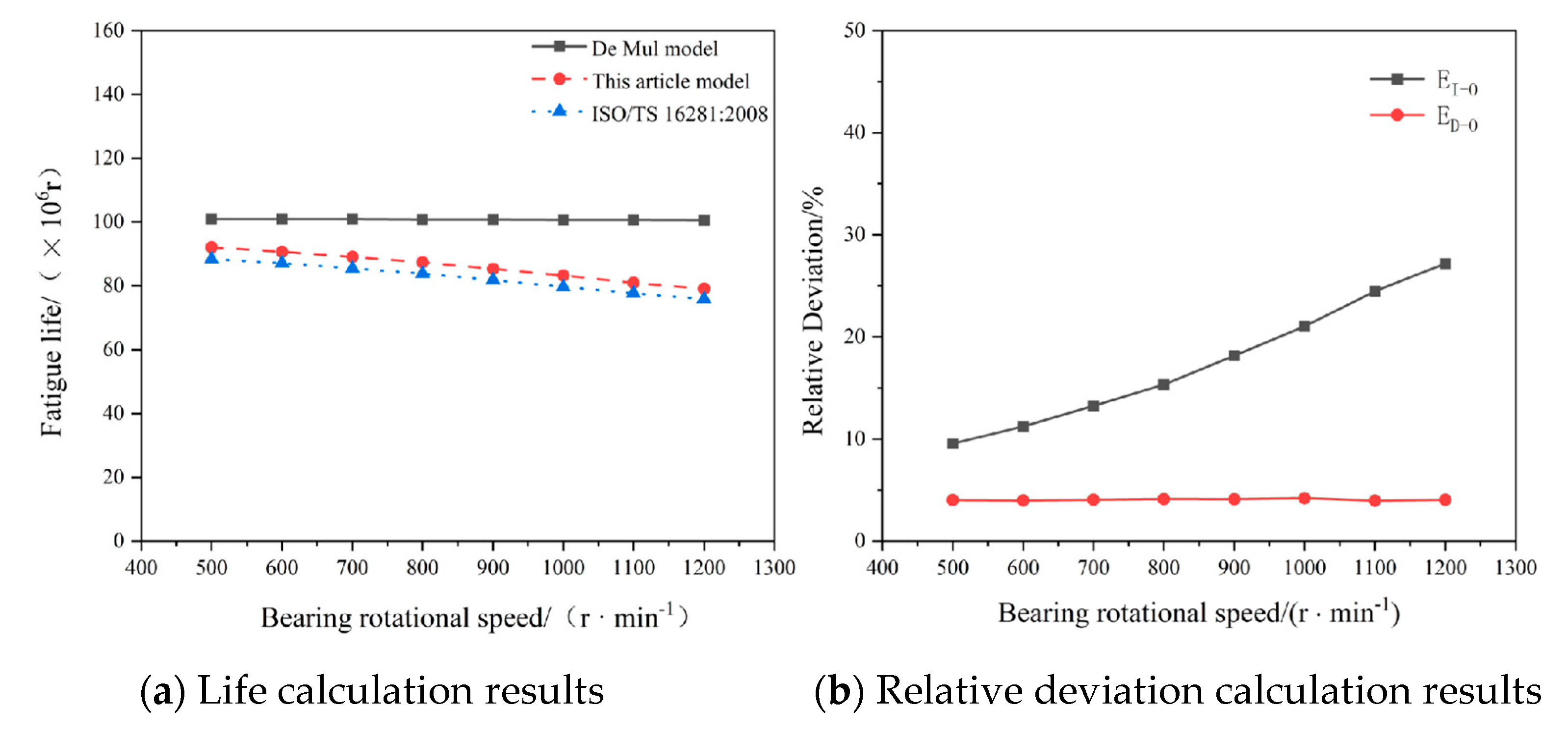
4.5. Effect of Inner Ring Rotational Speed Variations on Bearing Fatigue Life
The rotational speed of cylindrical roller bearings directly influences the entrainment velocity between rollers and bearing rings, thereby affecting the formed film thickness and ultimately impacting the system’s overall fatigue life.
Table 6 shows the influence of bearing speeds from 500 r/min to 1200 r/min on the overall fatigue life when the parameters of the cylindrical roller bearing in
Table 3 are used, the pure radial force is 160 KN, and the initial viscosity of lubricating oil is 0.193 Pa·s.
As demonstrated in
Table 6, (1) the De Mul model’s calculated bearing fatigue life exhibits minimal sensitivity to rotational speed variations, as its lubrication-free assumption restricts speed effects to centrifugal force changes. (2) The results from the proposed theoretical model reveal a progressive reduction in system fatigue life with increasing rotational speed. This occurs because rotational speed severely affects oil film thickness calculations across lubrication states, which subsequently governs the magnitude of elastic deformation and thereby influences contact load distribution and fatigue life.
Figure 12 provides the lifespan calculation results from three models, along with the relative deviations between the proposed theoretical model and the De Mul model, as well as between the proposed model and ISO/TS 16281:2008-based calculations.
4.6. Effect of Different Lubricant Viscosities on the Fatigue Life of Bearings
As analyzed in the preceding context, the oil film thickness formed during bearing operation exerts considerable influence on the overall fatigue life of the bearing. The initial viscosity of the lubricating oil undoubtedly has a significant impact on both the oil film thickness and pressure.
Table 7 presents the effects of progressively increasing the initial lubricant viscosity from 0.013 to 0.223 on the bearing’s overall fatigue life when applying the parameters of cylindrical roller bearings listed in
Table 2 and the operating condition parameters specified in
Table 3.
As can be observed from
Table 7, (1) since the De Mul model does not consider the influence of lubrication factors, variations in the initial lubricant viscosity have no effect on the bearing fatigue life calculated based on the De Mul model, and (2) as the proposed theoretical model in this study incorporates elastohydrodynamic lubrication effects, the center pressure of the elastohydrodynamic oil film decreases while the overall oil film thickness gradually increases with a progressive increase in initial lubricant viscosity, consequently leading to a gradual reduction in the bearing fatigue life calculated by the model.
Figure 13 illustrates the bearing fatigue life and relative deviations computed using three different calculation methods.
5. Bearing Fatigue Life Test
This study focuses on the SKF N324 supporting bearing located on the main shaft of the SFW250-8/850 horizontal hydro-generator, manufactured by Harbin Electric Machinery Co., Ltd. in Harbin, China. The fatigue life tests conducted on the medium-sized 2-CGSM-220 conventional life testing machine produced by Luoyang Bearing Research Institute Co., Ltd. in Luoyang, China validated the correctness of the theoretical model established in this study.
Bearing test operating conditions: Fatigue life tests were performed on the bearing under the light-load conditions specified in
Table 3 and the heavy-load conditions provided in
Table 4.
Monitoring and failure criteria for bearing fatigue tests: An increase in bearing vibration amplitude accompanied by regular spike waves—fatigue spalling, indentations, or localized damage on the bearing contact surfaces during testing will significantly amplify the vibration amplitude—and a vibration amplitude within 60 ~100 are identified as bearing failures, requiring shutdown for inspection. Fatigue failure is confirmed when flaking of the base metal with an area not less than 1 mm2 and a depth not less than 0.05 mm is observed on the working surfaces of the rolling elements or rings of the tested bearing.
Fatigue test protocol: The test is terminated upon fatigue failure, with the recorded fatigue life serving as the experimental result.
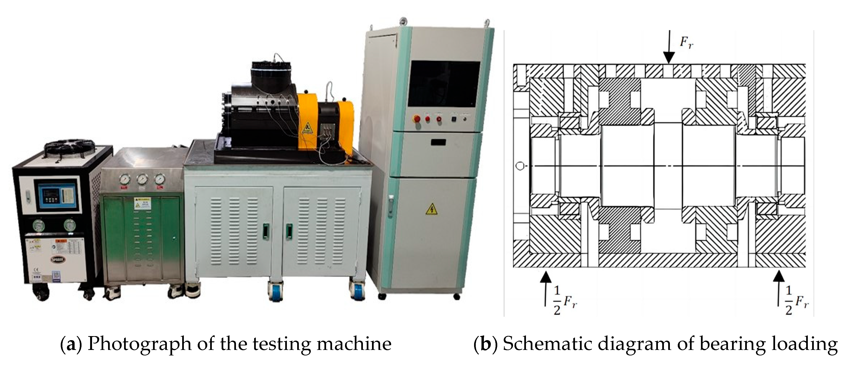
5.1. Fatigue Life Testing Machine
The CGSM-220 medium-sized conventional life testing machine employed in this study is designed for durability performance evaluations of rolling bearings under dynamic loading conditions. This machine enables the application of radial and axial loads to rolling bearings under dynamic loading; supports automatic speed and load variation testing; and provides real-time monitoring and recording of bearing speed, load, temperature, vibration, and current during experiments.
The bearing fatigue life testing machine is illustrated in
Figure 14.
5.2. Fatigue Life Test Results
Fatigue life tests were conducted on a total of eight sets of N324 bearings under the light-load conditions specified in
Table 3 and the heavy-load conditions specified in
Table 4. The resultant data from these completed tests are presented in
Table 8 and
Table 9.
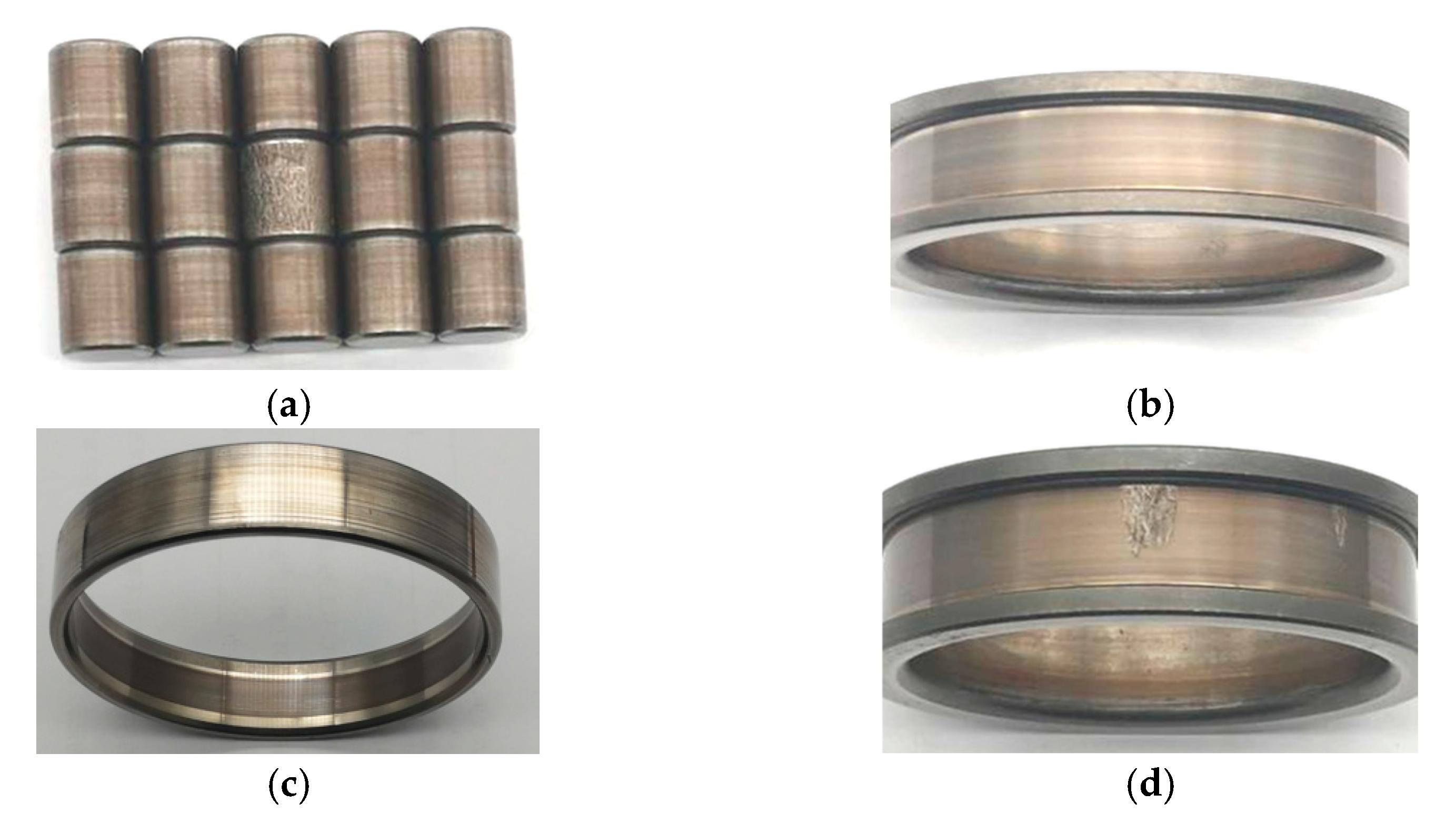
Photographs of the failed components of the specimen after the fatigue life test are presented in
Figure 15.
The experimental results shown in
Table 8 and
Table 9 as well as
Figure 15 reveal that a flaking phenomenon occurred on the rollers of bearing No. 1; bearing No. 4 failed due to inner ring slippage during operation; flaking occurred on the inner ring of bearing No. 5; and slight indentation microcracks appeared on the outer ring of bearing No. 6.
From these observations, it can be concluded that after completion of the tests, most failed bearings exhibited fatigue flaking and microcracking phenomena, indicating that the primary failure mode of the bearings was fatigue failure.
5.3. Comparison Between Fatigue Life Test Results and Model Calculation Results
To verify the accuracy of the theoretical model, this study conducted a comparative analysis of bearing fatigue test results. The calculated bearing life (L
De) obtained using the De Mul model (without considering lubrication effects), the theoretical model considering lubrication correction (L
E), and the fatigue test results (L
S) were compared. The test results are presented in
Table 10.
An analysis of
Table 10 reveals that discrepancies exist between the model calculation results and the actual experimental data, with theoretical model predictions generally overestimating experimental fatigue life.
The fatigue life of test bearings exhibits substantial variability, which primarily stems from the inherent stochastic nature of material fatigue. Even bearings with identical structures, dimensions, and manufacturing processes still demonstrate significant discrepancies in service life under equivalent operating conditions.
A comparative analysis after eliminating abnormal data shows that the measured average life under light-load conditions reaches 1.4715 × 10⁸ revolutions, while under heavy-load conditions, it reduces to 1.617 × 10⁷ revolutions. The De Mul model demonstrates an average error of 16.4% compared with experimental results, whereas the lubrication-considered model shows a reduced average error of 5.88%. These deviation values confirm that the bearing life prediction model based on the De Mul model exhibits insufficient prediction accuracy due to inadequate consideration of the influencing factors.
An analysis of
Table 8 and
Table 9 indicates that bearing No. 1, No. 5, and No. 6 exhibited fatigue flaking and microcracking phenomena in their components post-testing, with their failure modes classified as fatigue failures. Therefore, these three sets of experimental results were selected as validation benchmarks for the established fatigue life prediction model.
As shown in
Table 10, when lubrication was not considered, the test results of bearing No. 1 exhibited an 18.7% deviation from model calculations, while incorporating the effects of lubrication factors reduced this error to 5.2%, representing a reduction of 12.9 percentage points; for specimen No. 5, the error decreased from 20.9% to 2.7%, corresponding to a reduction of 18.2 percentage points; and for specimen No. 6, the error was reduced from 25.2% to 8.0%, constituting a decrease of 17.2 percentage points.
Comparisons between the lubrication-corrected and De Mul (non-lubricated) models reveal significant convergence trends in the deviations between calculated and measured values across all three specimens. This confirms that the established lubrication-modified bearing fatigue life calculation model effectively enhances prediction accuracy. A further analysis indicates that the lubrication-considered model maintains an average difference of approximately 5.3% from the experimental data, representing a 16.1% improvement in prediction accuracy (mean value) compared with conventional models.
These improvements demonstrate the critical role of lubrication factors in bearing life prediction and validate the engineering applicability of the lubrication modification modeling methodology proposed in this study.


