

Analysis of Influence of Cut-and-Cover Method on Retaining Structures and Differential Settlement in Subway Foundation Pit Construction


Abstract
1. Introduction
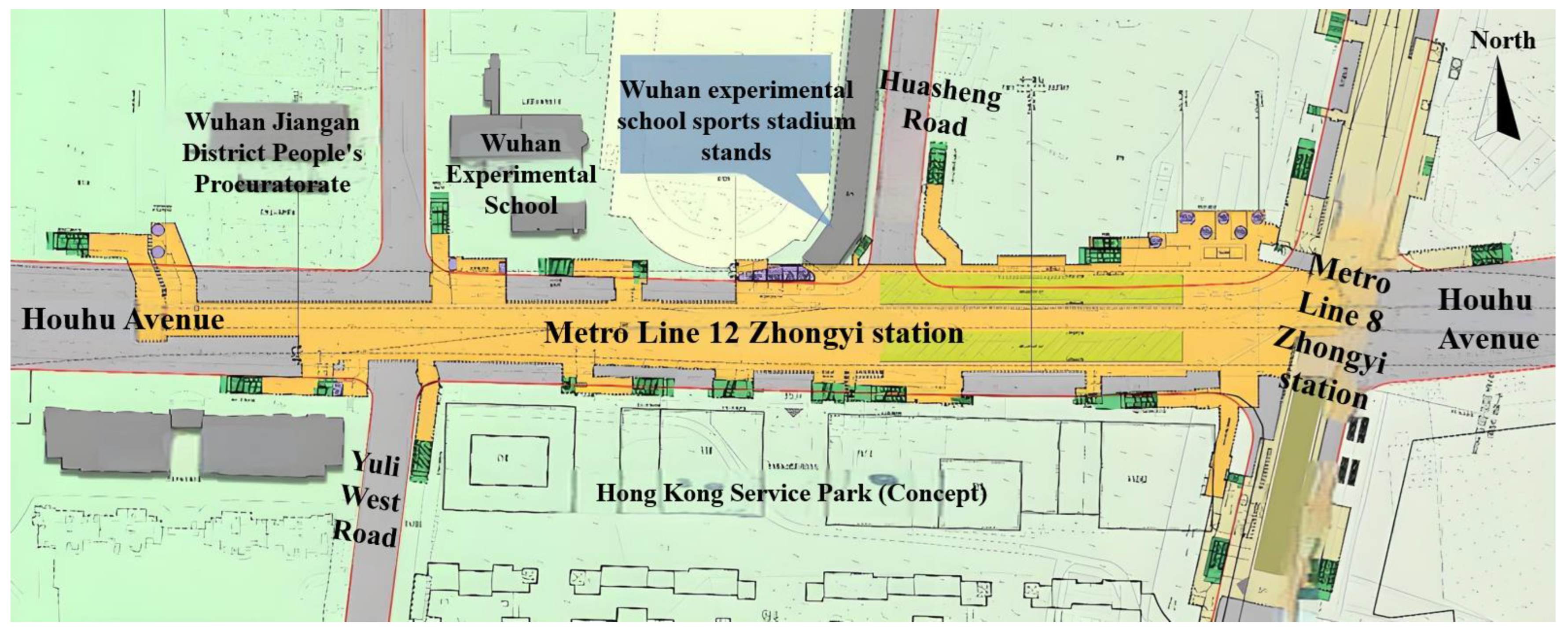
2. Project Overview
3. Numerical Simulation of Deep Foundation Pit
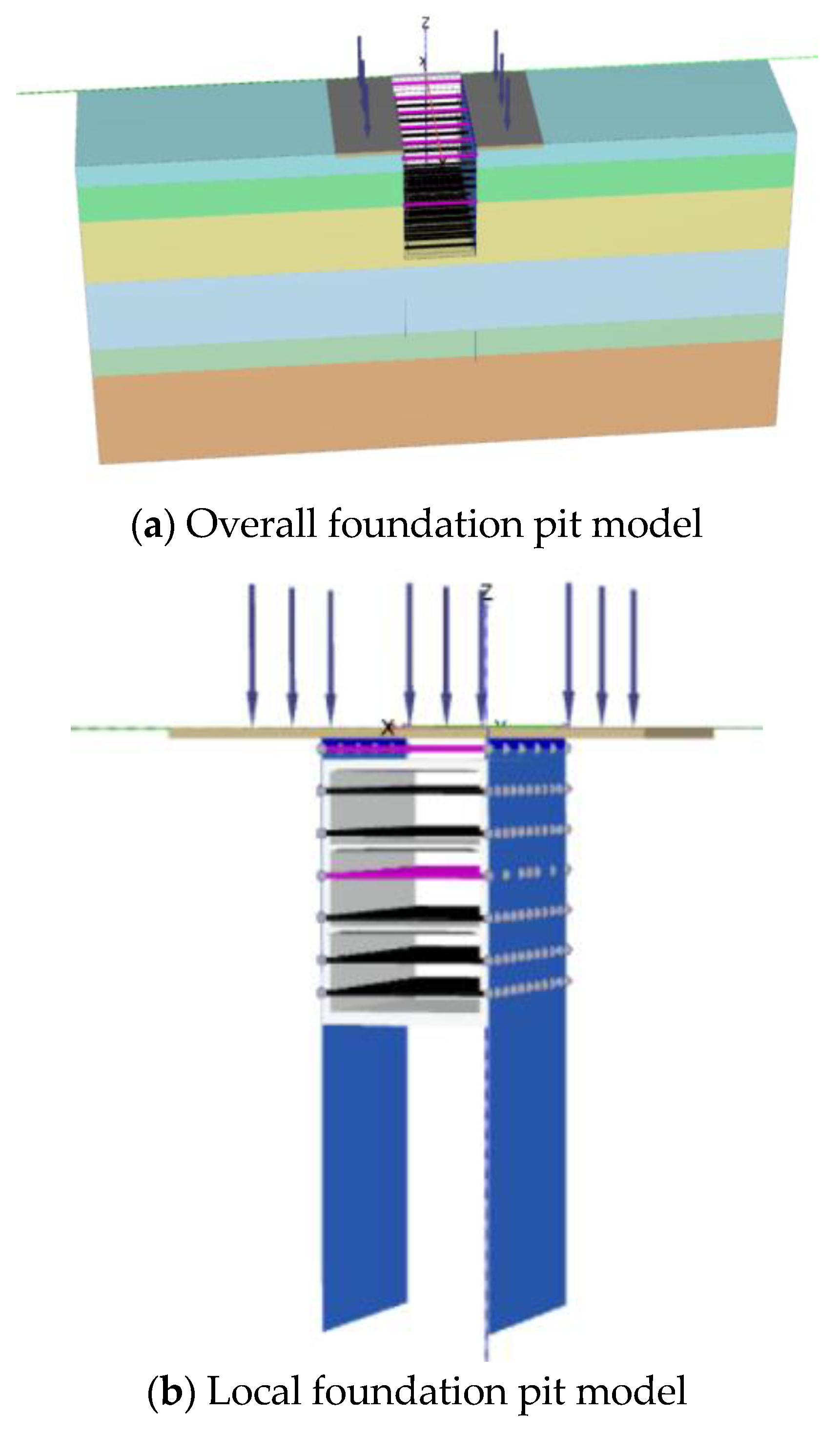
3.1. Model Establishment
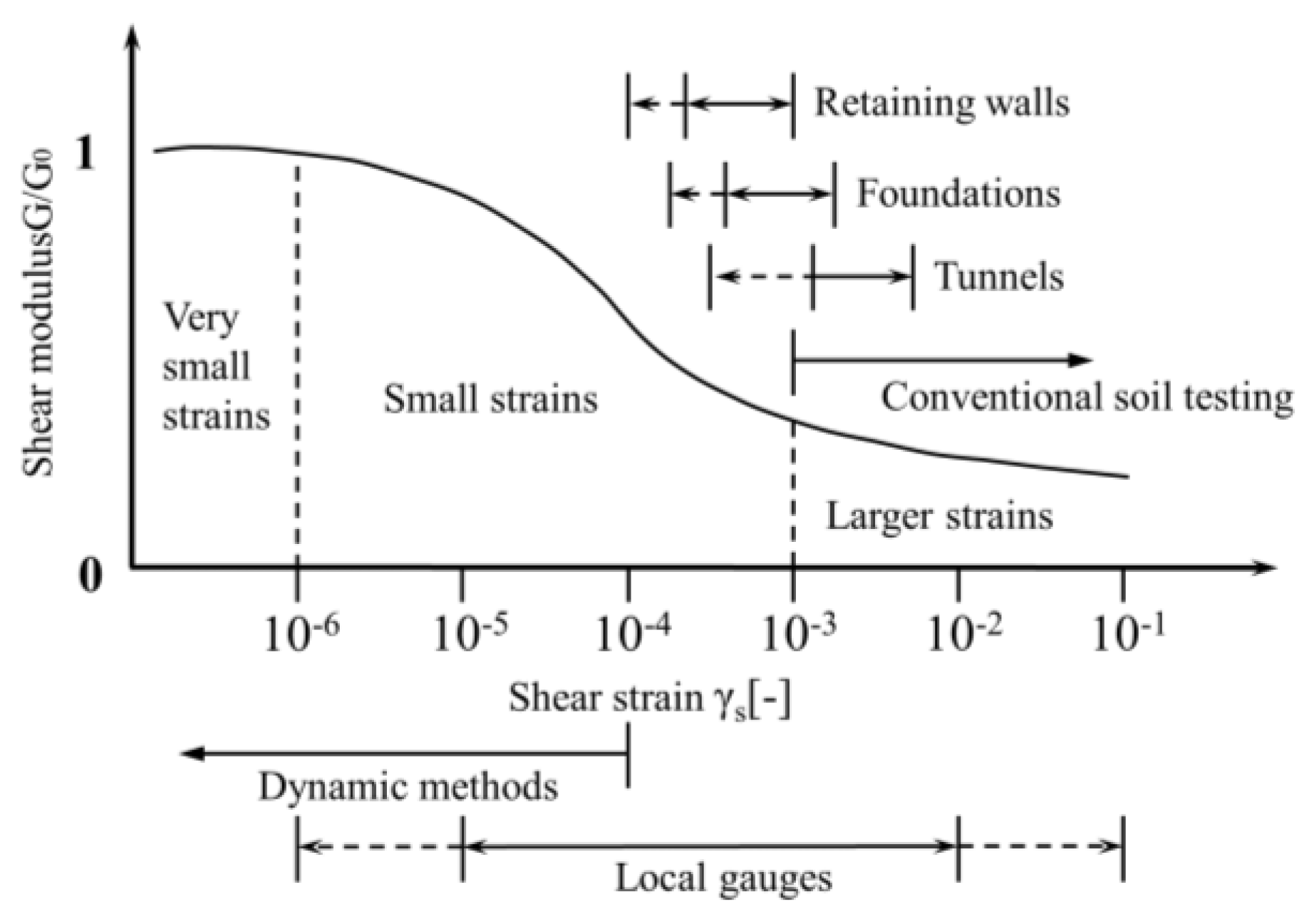
3.2. Selection of Model Parameters
3.3. Validation of the Numerical Model
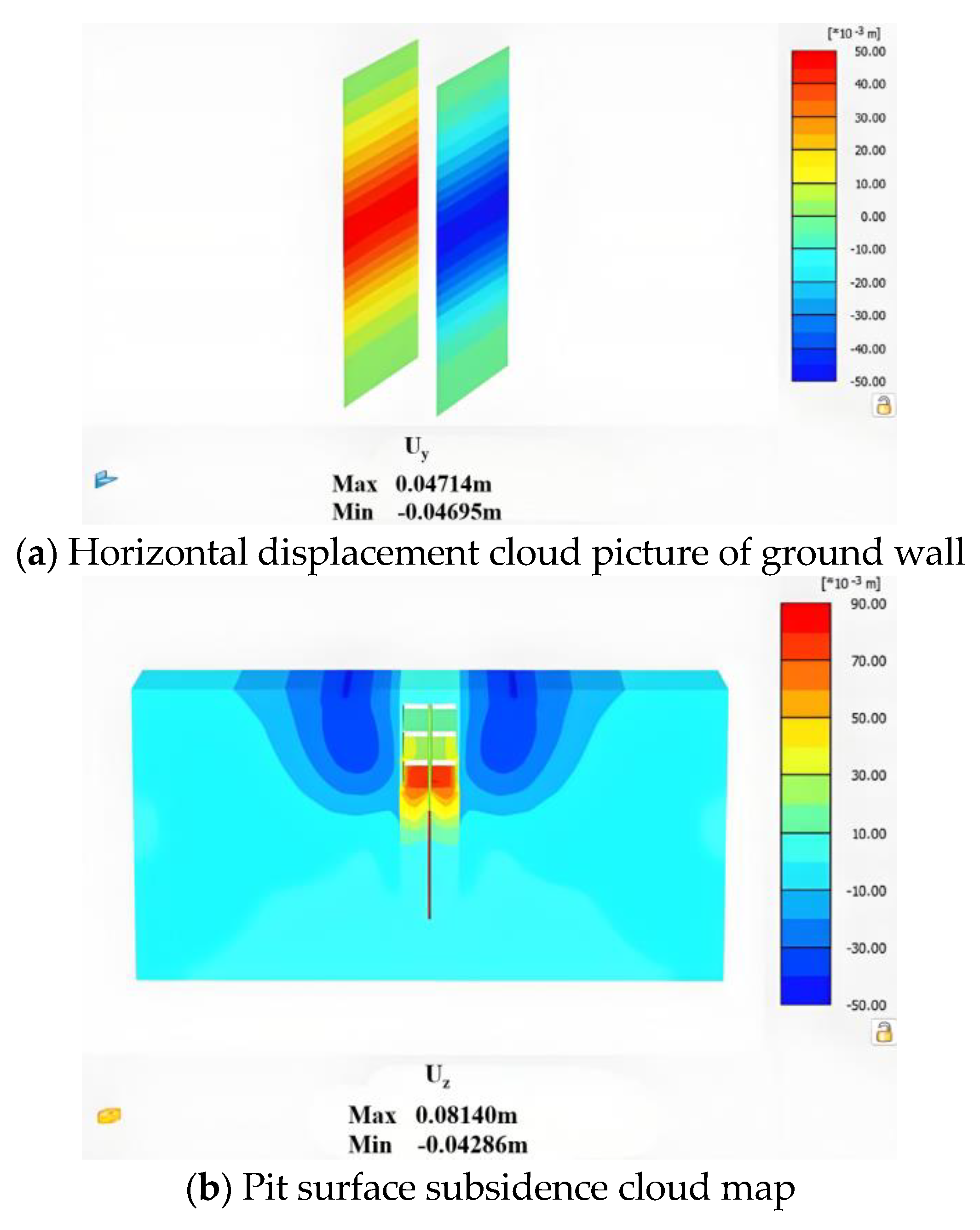
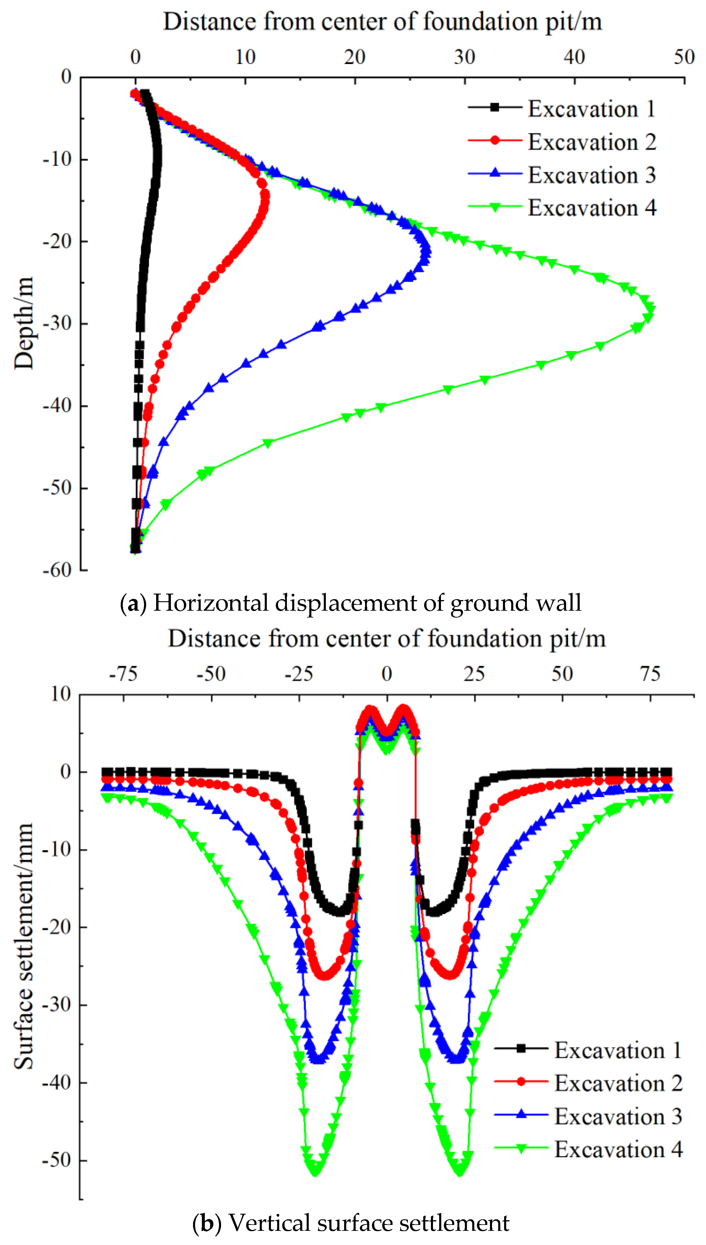
3.4. Analysis of Numerical Results
4. Comparative Analysis of Top-Down Method and Cut-and-Cover Method
4.1. Top-Down Method Model Establishment
4.2. Comparative Analysis of Simulation Results
4.2.1. Foundation Pit Deformation
4.2.2. Main Structure Internal Force
5. Deformation Control Measures
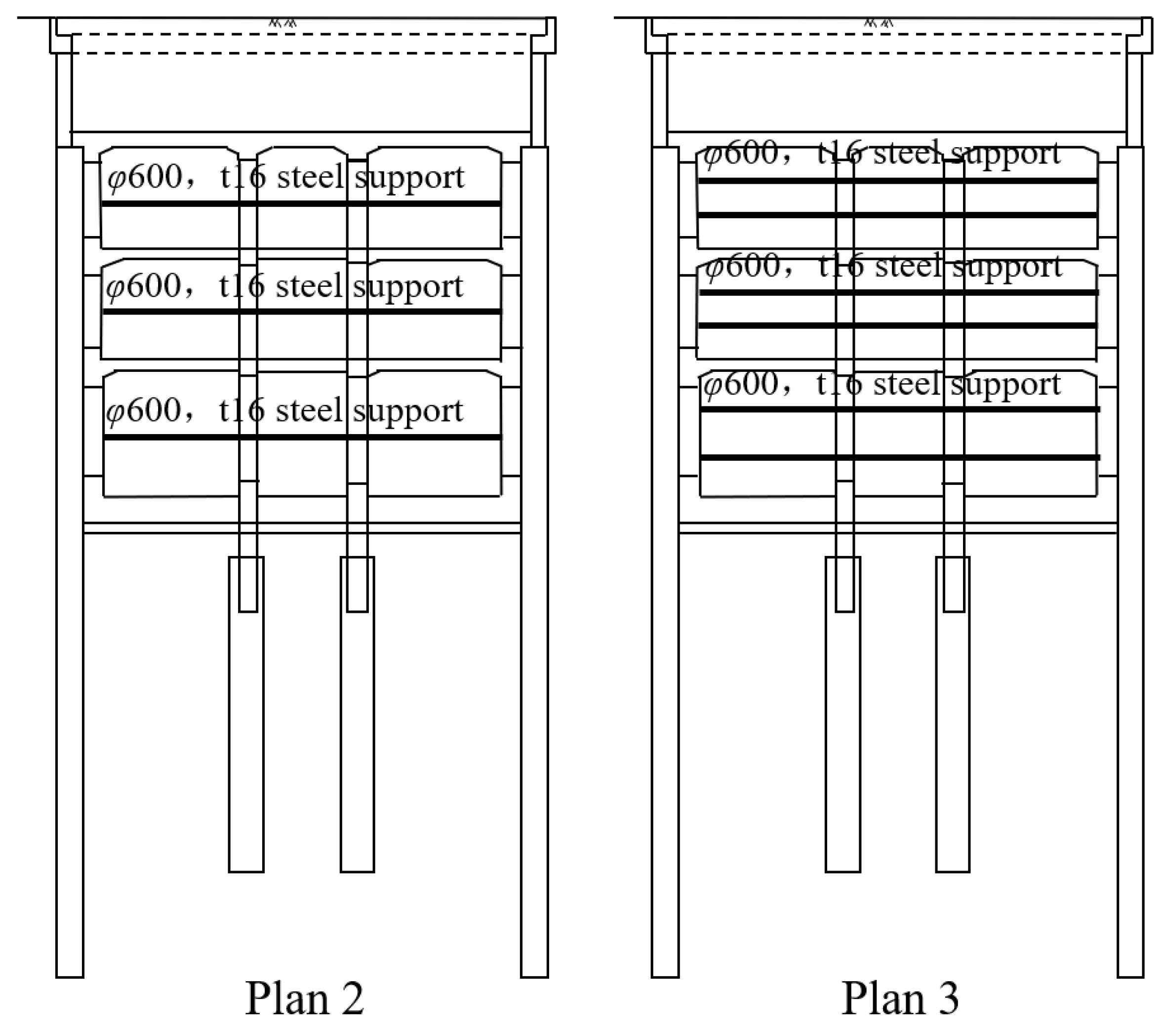
5.1. Determination of Deformation Control Scheme
5.2. Comparative Analysis of Deformation Results
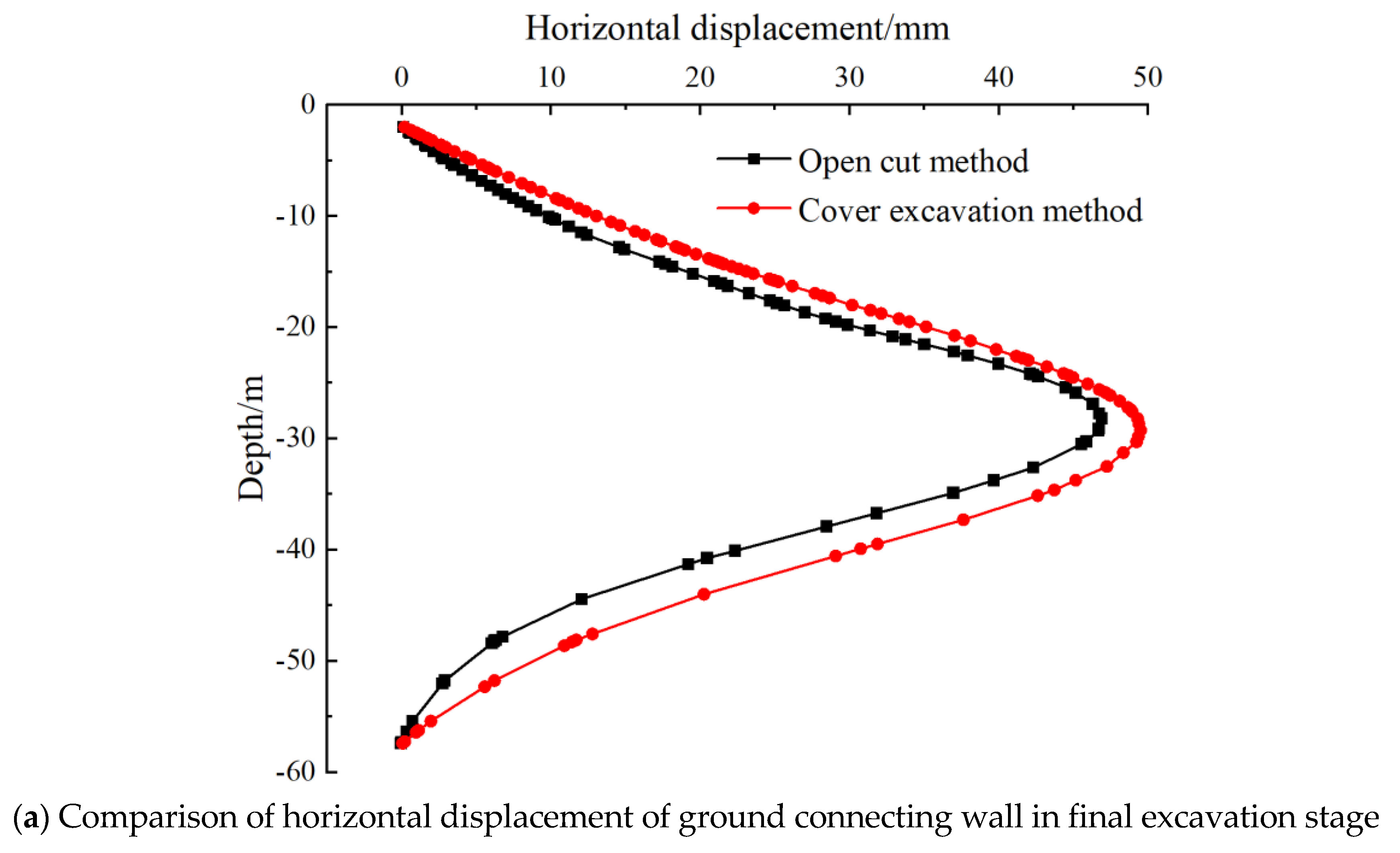
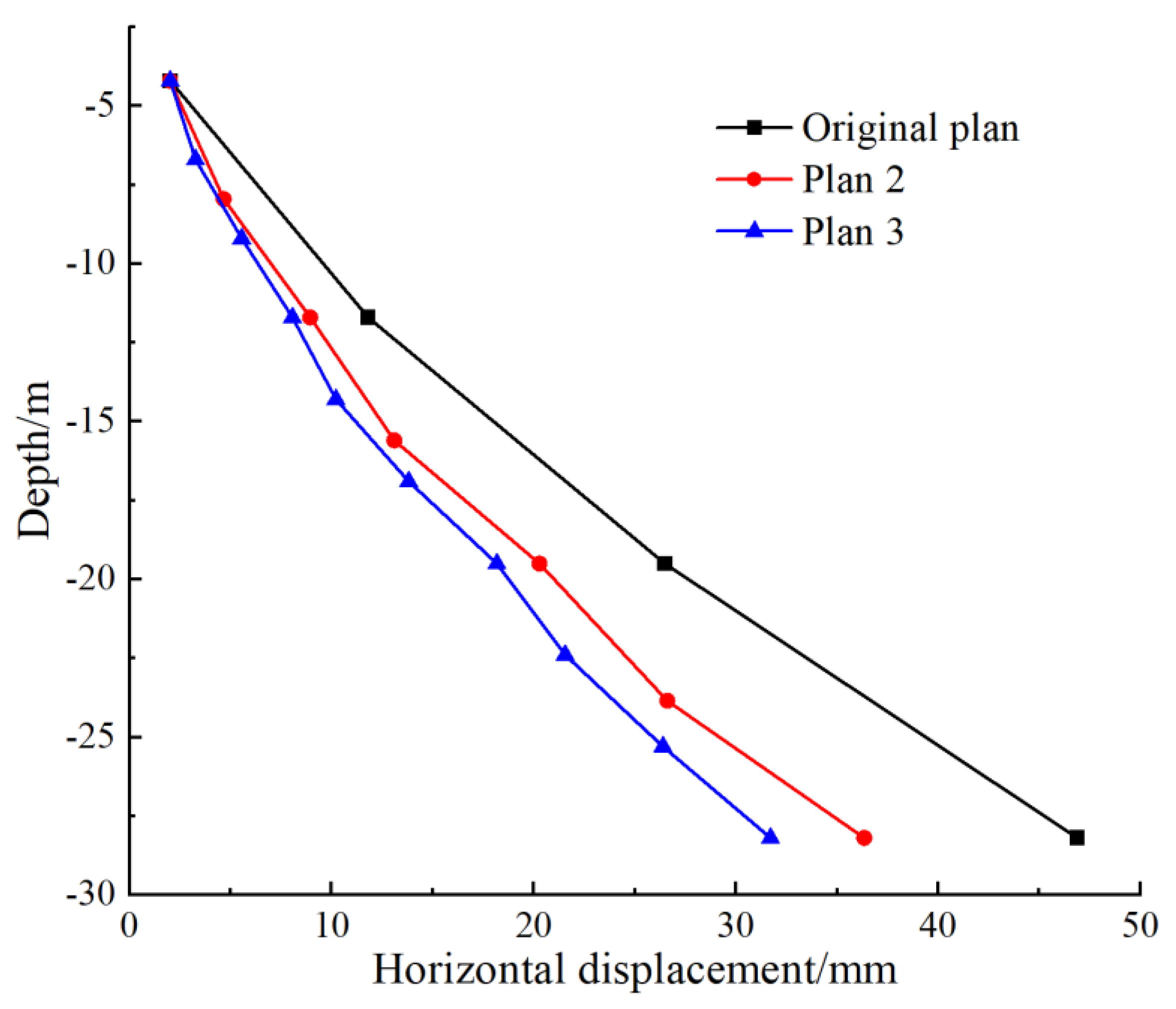
5.2.1. Comparative Analysis of Support Structure Deformation
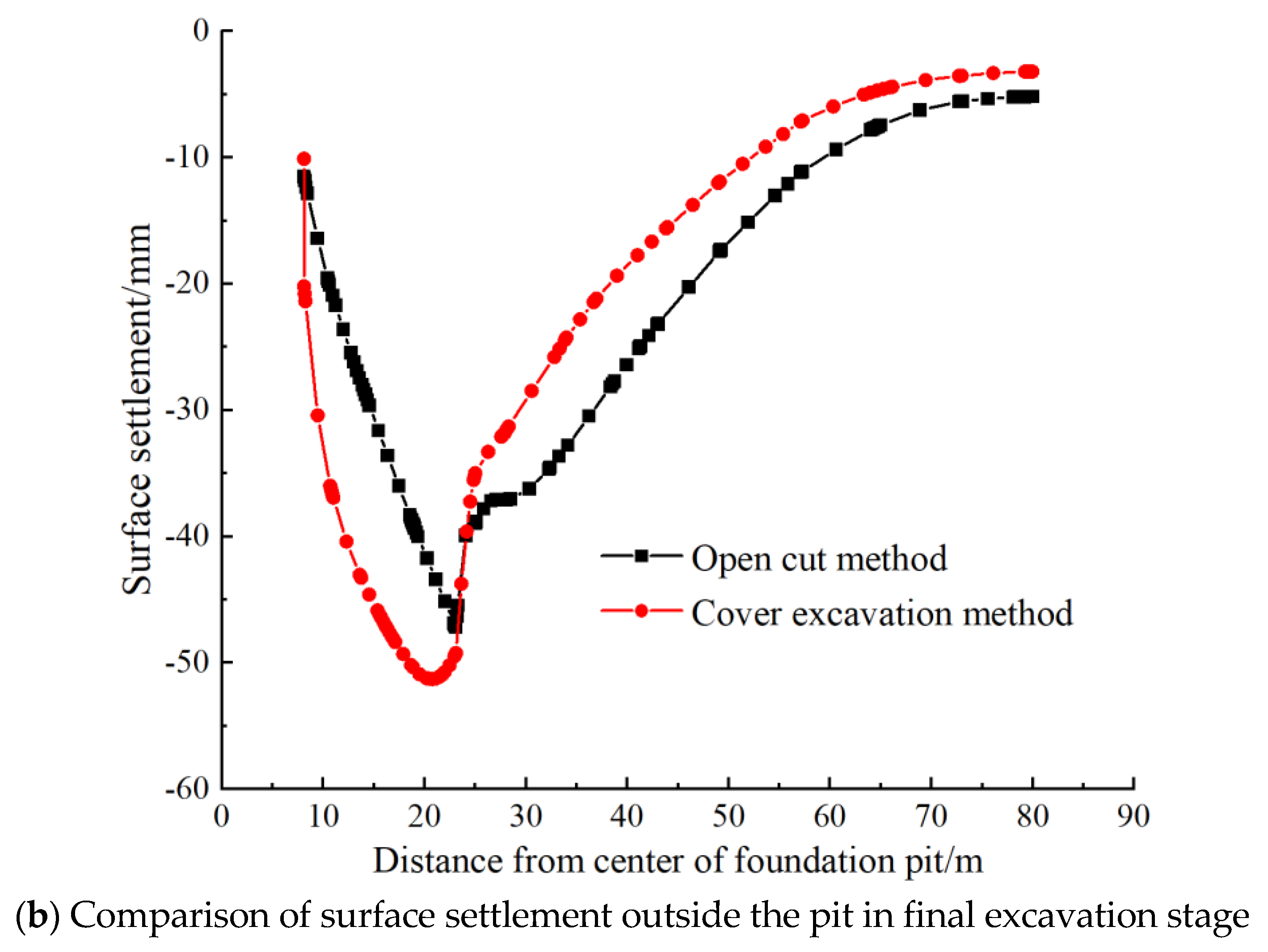
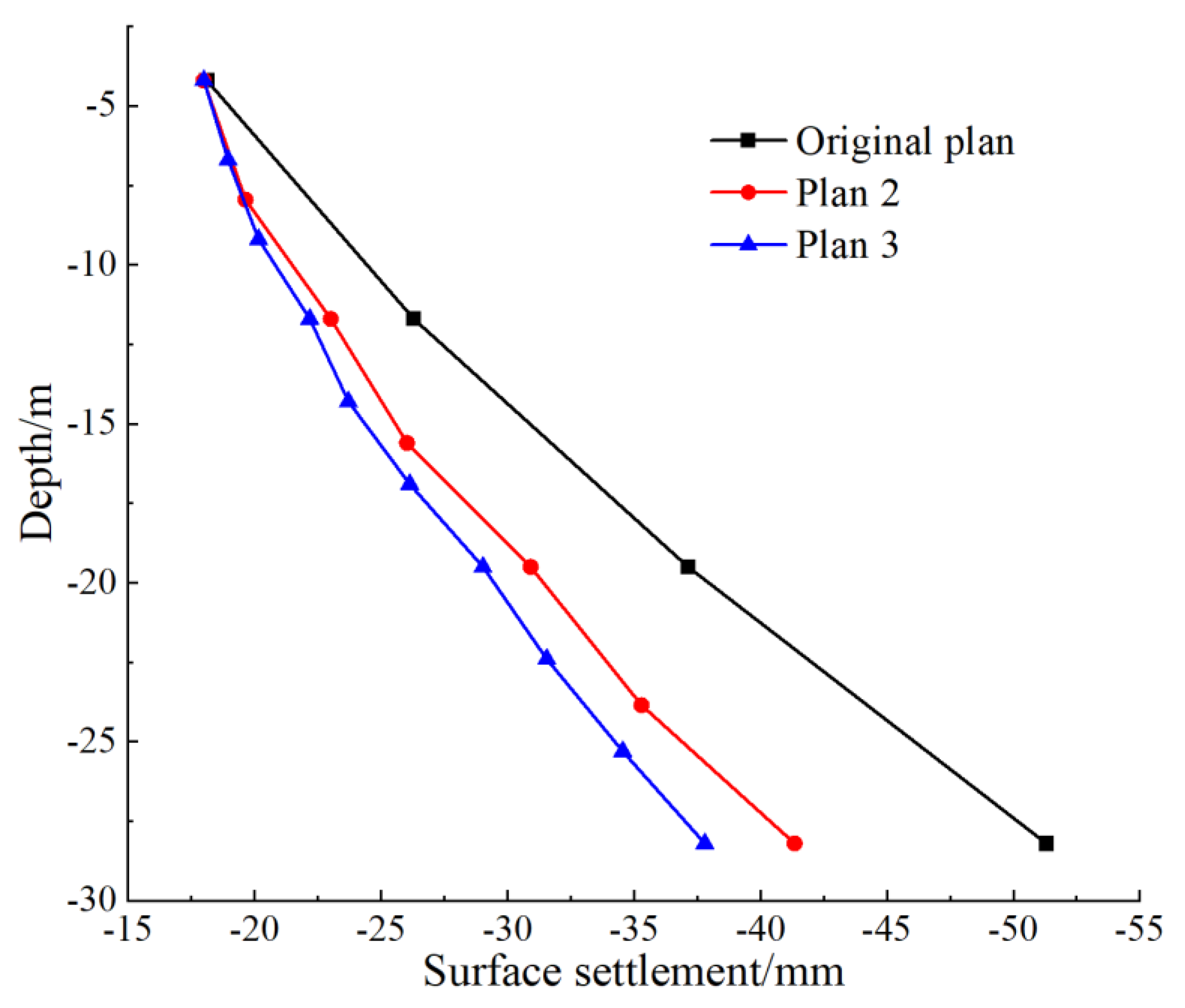
5.2.2. Comparative Analysis of Ground Surface Settlement
5.2.3. Comparative Analysis of Differential Settlement Between Ground Wall and Lattice Column
5.2.4. Engineering Cost Comparison Analysis
6. Conclusions
- (1)
- Both the horizontal displacement of the diaphragm wall and the ground surface settlement gradually increased with the excavation of the foundation pit, while the differential settlement between the diaphragm wall and the lattice columns showed a differential settlement that initially decreased then increased.
- (2)
- Comparative analysis with the cut-and-cover method indicated that the top-down method is more effective in terms of controlling the deformation of the foundation pit and reducing the impact of construction activities on the surrounding environment.
- (3)
- A construction scheme was proposed, involving multiple segmented pouring of the main structure and erection of internal supports. This scheme can effectively reduce the deformation of the foundation pit. However, in this project, with the increase in the number of segments, the growth of the deformation control effect is not obvious. Therefore, in this project, considering deformation and economy comprehensively, Plan 2 is selected as the best.
- (4)
- In future research, real-time monitoring data will be incorporated. By installing sensors in actual engineering projects, real-time data on soil deformation, stress, and other key parameters will be collected. This will be used to verify the accuracy of the numerical simulation results and further optimize the model parameters. At the same time, the adaptability and stability of each scheme in diverse geological environments will be evaluated.
Author Contributions
Funding
Data Availability Statement
Conflicts of Interest
References
- Bin, C.; Benson, H. Observations of the ground and structural behaviours induced by a deep excavation in loose sands. Acta Geotech. 2019, 15, 1577–1593. [Google Scholar]
- Wei, G.; Wang, Q.; Zhou, X.; Feng, F.; Wang, X.; Zhang, L.; Liang, L. Experiments and numerical simulation of the reinforcement effect of channel-steel-reinforced shield tunnel segments under unloading conditions. Eur. J. Environ. Civ. Eng. 2023, 27, 4142–4164. [Google Scholar] [CrossRef]
- Wei, G.; Qi, Y.; Chen, C.; Zhang, S.; Qian, C.; Zhou, J. Analysis of the protective effect of setting isolation piles outside the foundation pit on the underpass tunnel side. Transp. Geotech. 2022, 35, 100791. [Google Scholar] [CrossRef]
- Paulson, B.C.; Msce, M. Underground transit station construction in Japan. J. Constr. Div. 1982, 108, 23–37. [Google Scholar] [CrossRef]
- Tan, Y.; Li, M. Measured performance of a 26 m deep top-down excavation in downtown Shanghai. Can. Geotech. J. 2011, 48, 704–719. [Google Scholar] [CrossRef]
- Tan, Y.; Huang, R.; Kang, Z.; Bin, W. Covered semi-top-down excavation of subway station surrounded by closely spaced buildings in downtown Shanghai: Building response. J. Perform. Constr. Facil. 2016, 30, 04016040. [Google Scholar] [CrossRef]
- Lin, Z.; Xie, S.; Xia, C.; Dou, H. Design and Practice of Deep Foundation Pits for Large Storage Ponds in Complex Environments. Sustainability 2022, 14, 14046. [Google Scholar] [CrossRef]
- Zhang, Z.; Gao, Y.; Zheng, X.; Cao, J.; Chen, Y. Development and Application of Similar Materials for Foundation Pit Excavation Model Test of Metro Station. Appl. Sci. 2022, 12, 12880. [Google Scholar] [CrossRef]
- Farzi, M.; Pakbaz, S.M.; Aminpour, A.H. Selection of support system for urban deep excavations: A case study in Ahvaz geology. Case Stud. Constr. Mater. 2018, 8, 131–138. [Google Scholar] [CrossRef]
- Hsiung, B.C.B.; Yang, K.H.; Aila, W.; Ge, L. Evaluation of the wall deflections of a deep excavation in Central Jakarta using three-dimensional modeling. Tunn. Undergr. Space Technol. 2018, 72, 84–96. [Google Scholar] [CrossRef]
- Bozkurt, S.; Abed, A.; Karstunen, M. Finite element analysis for a deep excavation in soft clay supported by lime-cement columns. Comput. Geotech. 2023, 162, 105687. [Google Scholar] [CrossRef]
- Russo, G.; Nicotera, M.V.; Esposito, I. 3D FEM Back Analysis of the Observed Performance of a Very Deep Excavation in the Historical Center of Naples, Italy. J. Geotech. Geoenviron. Eng. 2024, 150, 04024010. [Google Scholar] [CrossRef]
- Lin, Z.; Jiang, Y.; Xu, C.; Chi, M.; Fang, T.; Guan, L.; Feng, G.; Lin, G. Performance of adjacent metro tunnels during deep excavation: A case study in Hangzhou. Transp. Geotech. 2025, 53, 101585. [Google Scholar] [CrossRef]
- Liu, Y.; Huang, W.; Mei, H.; Qin, X.; Wang, J. Analyze the deformation mechanism of foundation pit engineering and its influence on adjacent piers. Acad. J. Eng. Technol. Sci. 2022, 5, 1–4. [Google Scholar]
- Li, Z.; Zhao, G.F.; Deng, X.; Zhu, J.; Zhang, Q. Further development of distinct lattice spring model for stability and collapse analysis of deep foundation pit excavation. Comput. Geotech. 2022, 144, 104619. [Google Scholar] [CrossRef]
- Jamsawang, P.; Jamnam, S.; Jongpradist, P.; Tanseng, P.; Horpibulsuk, S. Numerical analysis of lateral movements and strut forces in deep cement mixing walls with top-down construction in soft clay. Comput. Geotech. 2017, 88, 174–181. [Google Scholar] [CrossRef]
- Li, M.G.; Chen, J.J.; Xu, A.J.; Xia, X.H.; Wang, J.H. Case study of innovative top-down construction method with channel-type excavation. J. Constr. Eng. Manag. 2014, 140, 05014003. [Google Scholar] [CrossRef]
- Yang, Z.; Chen, Y.; Azzam, R.; Yan, C. Performance of a top-down excavation in shanghai: Case study and numerical exploration. Eur. J. Environ. Civ. Eng. 2022, 26, 7932–7957. [Google Scholar] [CrossRef]
- Ou, C.Y.; Liao, J.T.; Lin, H.D. Performance of diaphragm wall constructed using top-down method. J. Geotech. GeoEnviron. Eng. 1998, 124, 798–808. [Google Scholar] [CrossRef]
- Whittle, A.J.; Hashash, Y.M.A.; Whitman, R.V. Analysis of deep excavation in Boston. J. Geotech. Eng. 1993, 119, 69–90. [Google Scholar] [CrossRef]
- Alkhdour, A.; Yasin, A.A.; Tiutkin, O. Rational design solutions for deep excavations using soil nail wall systems. Min. Miner. Depos. 2023, 17, 110–118. [Google Scholar] [CrossRef]
- Cai, M.; Kaiser, P.K.; Martin, C.D. Quantification of rock mass damage in underground excavations from microseismic event monitoring. Int. J. Rock Mech. Min. Sci. 2001, 38, 1135–1145. [Google Scholar] [CrossRef]
- Ono, J.; Murata, K. Construction of a very deep subway station using cut-and-cover method under high groundwater pressure. In Proceedings of the International Congress on Tunnelling and Ground Conditions, Cairo, Egypt, 3–7 April 1994; pp. 57–60. [Google Scholar]
- DG/TJ08-61-2018; Shanghai Engineering Construction Code-Technical Standard for Foundation Pit Engineering. Tongji University Publishing House: Shanghai, China, 2018.
- Sun, Y. Numerical Analysis of Top-Down Construction Technique and Study on Monitoring for Deep Excavation Engineering in Soft-Soil Areas. Ph.D. Thesis, Tongji University, Shanghai, China, 2006. [Google Scholar]
- Su, J.; Zhang, D.; Gao, Z.; Huang, J.; Xiao, C. Structural Deformation and Control of Subway Station Constructed by Cut and Cover Reverse method. Chins Railw. Sci. 2010, 31, 59–65. [Google Scholar]
- Guo, X.; Xie, X.; Jia, J. Differential displacement control of deep foundation pits in soft clay by use of top-down excavation method. Chin. J. Geotech. Eng. 2012, 34 (Suppl. S1), 72–76. [Google Scholar]
- Wang, Y. Finite element analysis of Differential settlement in the construction of the Cut-and-Cover method. Low-Temp. Build. Technol. 2012, 34, 103–105. [Google Scholar]


| Method | Advantages | Disadvantages |
|---|---|---|
| Top-Down Method | 1. Construction is simple: fewer processes and mature technology. 2. Short construction period: high degree of mechanization. 3. Low cost: The total cost is approximately 60–70% of that of the cut-and-cover method. 4. High space utilization: suitable for large-span foundation pits. | 1. Traffic disruption: roads need to be closed, affecting urban traffic. 2. Significant environmental impact: loud noise and dust. 3. Weather constraint: heavy rain may cause the foundation pit to be flooded. |
| Cut-and-Cover Method | 1. Minimize traffic impact: construct the roof first; then restore road traffic. 2. Good structural stability: utilizing permanent structures as supports and reducing the need for reinforcement. 3. Sediment control excellent: minimal disturbance, deformation of surrounding buildings < 10 mm. 4. Applicable to deep foundation pits: when the depth is greater than 20 m, the safety is high. | 1. Long construction period: complex process (piles → roof slab → reverse construction), 30–40% slower than open excavation. 2. High cost: the construction cost is approximately 1.3 to 1.5 times that of the open-cut method. 3. The construction is very challenging: the precision of node connections is extremely high (for example, the verticality of the steel pipe columns should be ≤1/500). |
| Name | Size (mm) | E (×103 kPa) | Poisonby |
|---|---|---|---|
| Diaphragm wall | 1500 | 31,500 | 0.22 |
| Steel supports | φ900 t = 16 | 210,000 | --- |
| Lattice column | φ900/φ2300 | 31,500 | 0.22 |
| Soil Layer | Name | γ (kN/m3) | c′ (kPa) | φ′ (°) | E50 (kPa) | Eoed (kPa) | Eur (kPa) | G0 (kPa) |
|---|---|---|---|---|---|---|---|---|
| 1-1 | Miscellaneous fill | 18.2 | 16 | 12 | 7300 | 7300 | 21,900 | 44,000 |
| 2-1 | Silty clay | 18.8 | 23 | 23 | 4500 | 4500 | 18,000 | 36,000 |
| 3-1 | Silt sand | 17.8 | 10 | 25 | 8500 | 8500 | 30,000 | 60,000 |
| 4-1 | Boulder | 19 | 11 | 24 | 9000 | 9000 | 27,000 | 54,000 |
| 5-1 | Heavily weathered rock | 19 | 20 | 30 | 10,000 | 10,000 | 30,000 | 60,000 |
| 6-1 | Moderately weathered rock | 20 | 50 | 30 | 200,000 | 200,000 | 600,000 | 12,000,000 |
| Analysis Conditions | Description of Working Condition |
|---|---|
| Stage 1 | Geostatic equilibrium |
| Stage 2 | Construction of upper enclosure structure |
| Stage 3 | Ground wall and lattice column construction (displacement reset) |
| Stage 4 | Excavation 1 (−3.0 m) |
| Stage 5 | The first-floor main structure construction |
| Stage 6 | Backfill traffic |
| Stage 7 | Excavation 2 (−11.7 m) |
| Stage 8 | The second-floor main structure construction |
| Stage 9 | Excavation 3 (−19.5 m) |
| Stage 10 | The third-floor main structure construction |
| Stage 11 | Excavation 4 (−28.2 m) |
| Stage 12 | The fourth floor main structure construction |
| Working Condition | Maximum Vertical Displacement of Ground Wall | Maximum Vertical Displacement of Lattice Column | Difference Value |
|---|---|---|---|
| The first-floor main structure construction | --- | --- | --- |
| The second-floor main structure construction | −1.23 | −0.98 | 0.25 |
| The third-floor main structure construction | −1.51 | −1.64 | 0.13 |
| The fourth-floor main structure construction | −3.76 | −3.02 | 0.74 |
| Analysis Conditions | Description of Working Condition |
|---|---|
| Stage 1 | Geostatic equilibrium |
| Stage 2 | Construction of upper enclosure structure |
| Stage 3 | Ground wall and lattice column construction (displacement reset) |
| Stage 4 | Set up the first brace |
| Stage 5 | Excavation 1 |
| … | … |
| Stage 15 | Set up a seventh brace |
| Stage 16 | Excavation 7 |
| Method | Maximum Longitudinal Compressive Stress/(kN/m2) | Maximum Longitudinal Tensile Stress/(kN/m2) |
|---|---|---|
| Top-Down | −4650 | 2017 |
| Cut-and-Cover | −3001 | 1897 |
| Working Condition | Maximum Vertical Displacement of Ground Wall | Maximum Vertical Displacement of Lattice Column | Difference Value |
|---|---|---|---|
| Original plan | −3.76 | −3.02 | 0.74 |
| Plan 2 | −3.16 | −3.71 | 0.55 |
| Plan 3 | −2.97 | −4.04 | 1.07 |
Disclaimer/Publisher’s Note: The statements, opinions and data contained in all publications are solely those of the individual author(s) and contributor(s) and not of MDPI and/or the editor(s). MDPI and/or the editor(s) disclaim responsibility for any injury to people or property resulting from any ideas, methods, instructions or products referred to in the content. |
© 2025 by the authors. Licensee MDPI, Basel, Switzerland. This article is an open access article distributed under the terms and conditions of the Creative Commons Attribution (CC BY) license (https://creativecommons.org/licenses/by/4.0/).
Share and Cite
Liu, Y.; Huang, L.; Tang, X.; Xue, Y.; Ke, W.; Luo, Y.; Guan, L. Analysis of Influence of Cut-and-Cover Method on Retaining Structures and Differential Settlement in Subway Foundation Pit Construction. Appl. Sci. 2025, 15, 7520. https://doi.org/10.3390/app15137520
Liu Y, Huang L, Tang X, Xue Y, Ke W, Luo Y, Guan L. Analysis of Influence of Cut-and-Cover Method on Retaining Structures and Differential Settlement in Subway Foundation Pit Construction. Applied Sciences. 2025; 15(13):7520. https://doi.org/10.3390/app15137520
Chicago/Turabian StyleLiu, Yi, Lei Huang, Xiaolin Tang, Yanbin Xue, Wenbin Ke, Yang Luo, and Lingxiao Guan. 2025. "Analysis of Influence of Cut-and-Cover Method on Retaining Structures and Differential Settlement in Subway Foundation Pit Construction" Applied Sciences 15, no. 13: 7520. https://doi.org/10.3390/app15137520
APA StyleLiu, Y., Huang, L., Tang, X., Xue, Y., Ke, W., Luo, Y., & Guan, L. (2025). Analysis of Influence of Cut-and-Cover Method on Retaining Structures and Differential Settlement in Subway Foundation Pit Construction. Applied Sciences, 15(13), 7520. https://doi.org/10.3390/app15137520