Article

An Electronically Adjustable Floating Memcapacitor Emulator Circuit Using CDBA

by
Sevgi Gursul Kalac
1,*,
Zehra Gulru Cam Taskiran
2 and
Serdar Ethem Hamamci
1
1
Electrical and Electronics Engineering Department, Inonu University, 44280 Malatya, Türkiye
2
Electronics and Communication Engineering Department, Yildiz Technical University, 34220 Istanbul, Türkiye
*
Author to whom correspondence should be addressed.
Appl. Sci. 2025, 15(13), 7506; https://doi.org/10.3390/app15137506
Submission received: 11 June 2025 / Revised: 30 June 2025 / Accepted: 30 June 2025 / Published: 3 July 2025
(This article belongs to the Section Electrical, Electronics and Communications Engineering)

Abstract

Memristive elements, known as memristors, memcapacitors and meminductors, have become an important topic of research in the electronics world in recent years. As there is still no efficient way to manufacture two-terminal memristive elements, many researchers have focused their efforts on designing emulator circuits that mimic these devices. In this study, a memcapacitor emulator circuit using Current Derivative Buffered Amplifier (CDBA) is proposed, which has significant advantages such as wide dynamic range, differential structure at the input port, high sloping rate and wide bandwidth. The main advantages of the emulator are that it is floating without grounding constraint, it is electronically adjustable, it has charge-controlled incremental and decremental modes and it has a simpler circuit structure since it does not contain a memristor. To ensure the integrity of the circuit theory, the results of the mathematical model and the simulation of the memcapacitor are given together. In addition, the characteristics of the experimentally investigated memcapacitor emulator are in good agreement with the simulation results. To provide an illustration of the performance of the proposed emulator, firstly the second-order active low-pass filter circuit and subsequently the amoeba learning circuit are selected as the working environment. The results show that the filtering performance of the proposed emulator at a value after the cut-off frequency in the filter circuit is 25 % more efficient than a standard capacitor and in terms of power consumption, it consumes 27.93 % less power than a standard capacitor. Moreover, the emulator successfully accomplishes the learning and data storage tasks in the amoeba learning circuit.

1. Introduction

With developments in technology, a low power consumption and a high processing speed have become the most sought-after features in electronic circuits [1]. Memristive elements, called memristors, memcapacitors and meminductors, which are similar to the resistor, capacitor and inductor elements but have memory specialty, are expected to provide these features demanded by the developing electronics world [2]. The investigation of memristive elements first began in 1971 with the memristor element [3]. The main difference between a memristor element and a standard resistor is that the element is defined by the relationship between electric charge and magnetic flux, rather than current and voltage. However, the relationship between the current and voltage of the memristor is in the form of a hysteresis curve that varies with frequency. This feature makes it possible to achieve new functions such as non-volatile memory and a variable resistance value depending on the direction and magnitude of the applied current [4]. After the discovery of the memristor element, its application areas have become a matter of curiosity and it has found a place in many areas, especially in neuromorphic systems [5,6,7,8,9,10,11], programmable Analog Circuits [12,13,14], chaotic circuits [15,16,17], image processing [18,19] and sensor applications [20,21,22].
In the following years, it was realized that the memory elements were not limited to the memristors, and new elements were introduced according to different relationships that had not been used before [23]. Accordingly, it was found that the relationship between the integral of the charge σ ( t ) and the magnetic flux φ ( t ) represents the memcapacitor element [24]. The memcapacitor is a lossless element and is more energy efficient compared to the memristor [25,26]. The ability of the memcapacitor to store energy without the need for a power source is one of the features that make this element interesting [27]. These properties of the memcapacitor make it possible to realize numerous applications such as chaotic oscillators [28,29,30], neuromorphic circuits [31,32,33,34,35], and logic circuits [36,37].
Circuit studies using memcapacitor elements are largely based on the use of various equivalent emulator designs in place of the element due to the lack of commercially available memcapacitor elements. Experimental performance, floating or grounded form, and electronic controllability are some important criteria for the quality of an emulator designed for the memcapacitor. A number of designs have been proposed for the memcapacitor in the literature [38,39,40,41,42]. In one study, a Current Backward Transconductance Amplifier (CBTA) element was used to form a mutator element, and a floating memcapacitor circuit was designed using this mutator element together with a grounded memristor and capacitor element [38]. In [39], a charge-controlled emulator model was proposed for grounded and floating memcapacitor emulators using two Second-Generation Current Conveyors (CCII), one analog multiplier (AM) and some passive elements. In another study [40], two memcapacitor emulators were proposed, one with two CCIIs and some passive elements and the other with one CCII, one Operational Transconductance Amplifier (OTA) and some passive elements, which were experimentally supported and designed to be electronically controllable. In [41], a floating memcapacitor emulator consisting of OTA, Voltage Difference Transconductance Amplifier (VDTA) and buffer obtained by using MOSFET transistors instead of ICs was designed and the results were experimentally verified. In another study using MOS technology, an emulator designed in floating mode with Dual X Current Conveyor Differential Input Transconductance Amplifier (DXCCDITA) element was simulated [42]. However, it can be seen that these emulators differ in the number of their active and passive elements, whether they are floating or grounded, experimentally verified, contain a memristor or are electronically controllable. Therefore, the design studies on memcapacitor emulator circuits continue with increasing interest.
In general, the work presented in this article includes the following innovations and contributions:
  • In our work, the CDBA element, which has important advantages such as wide dynamic range, high slope speed, differential structure at the input port and which has not been used in the design of memcapacitor emulators in the literature to the best of our knowledge, was used.
  • The memcapacitor emulator analyzed both in simulation and experimentally has the advantages of not having ground restriction, not having a memristor in its structure, being electronically adjustable and being able to operate in decreasing and increasing modes.
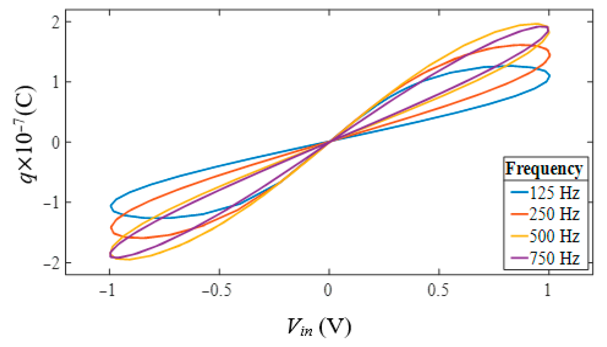
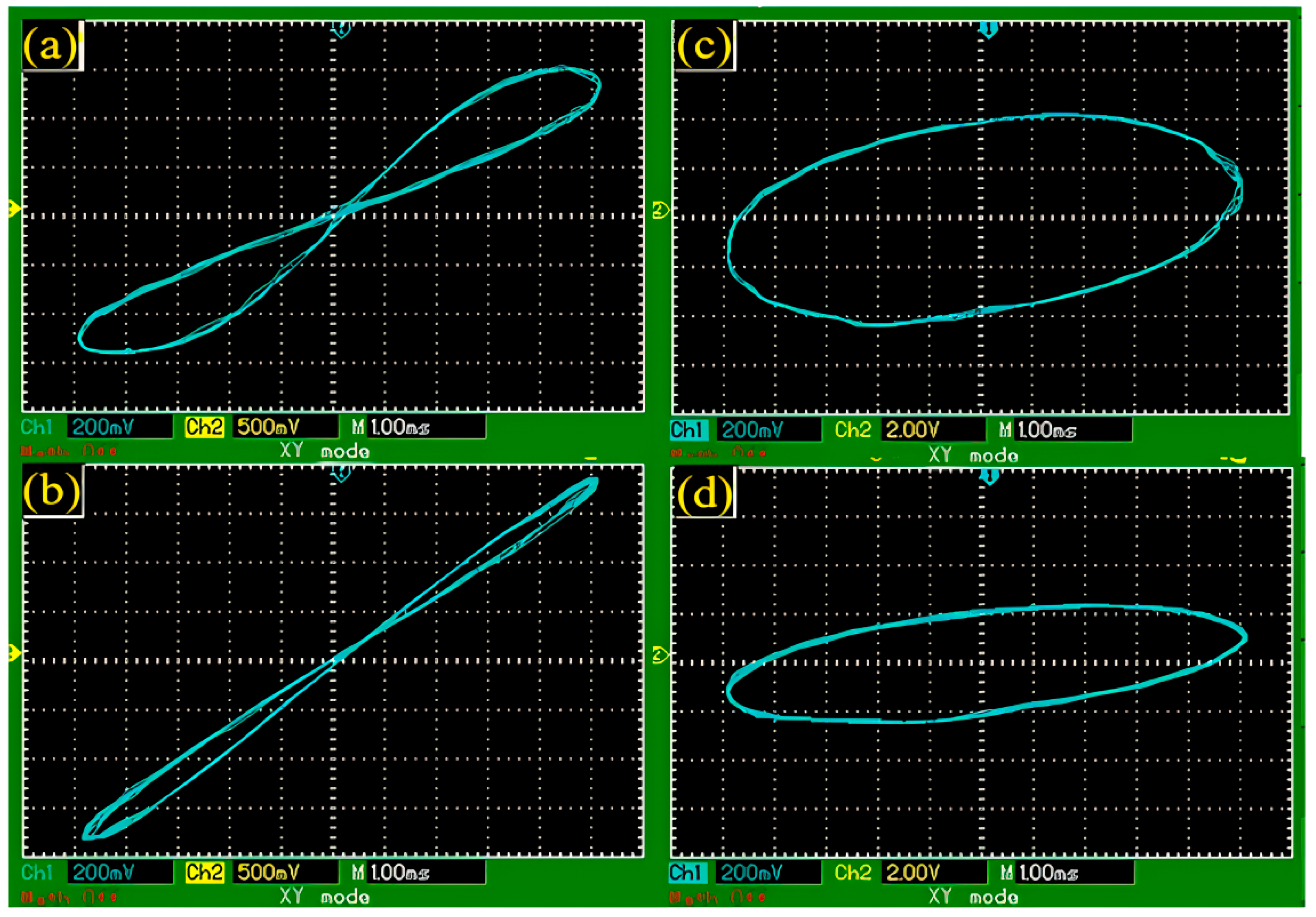
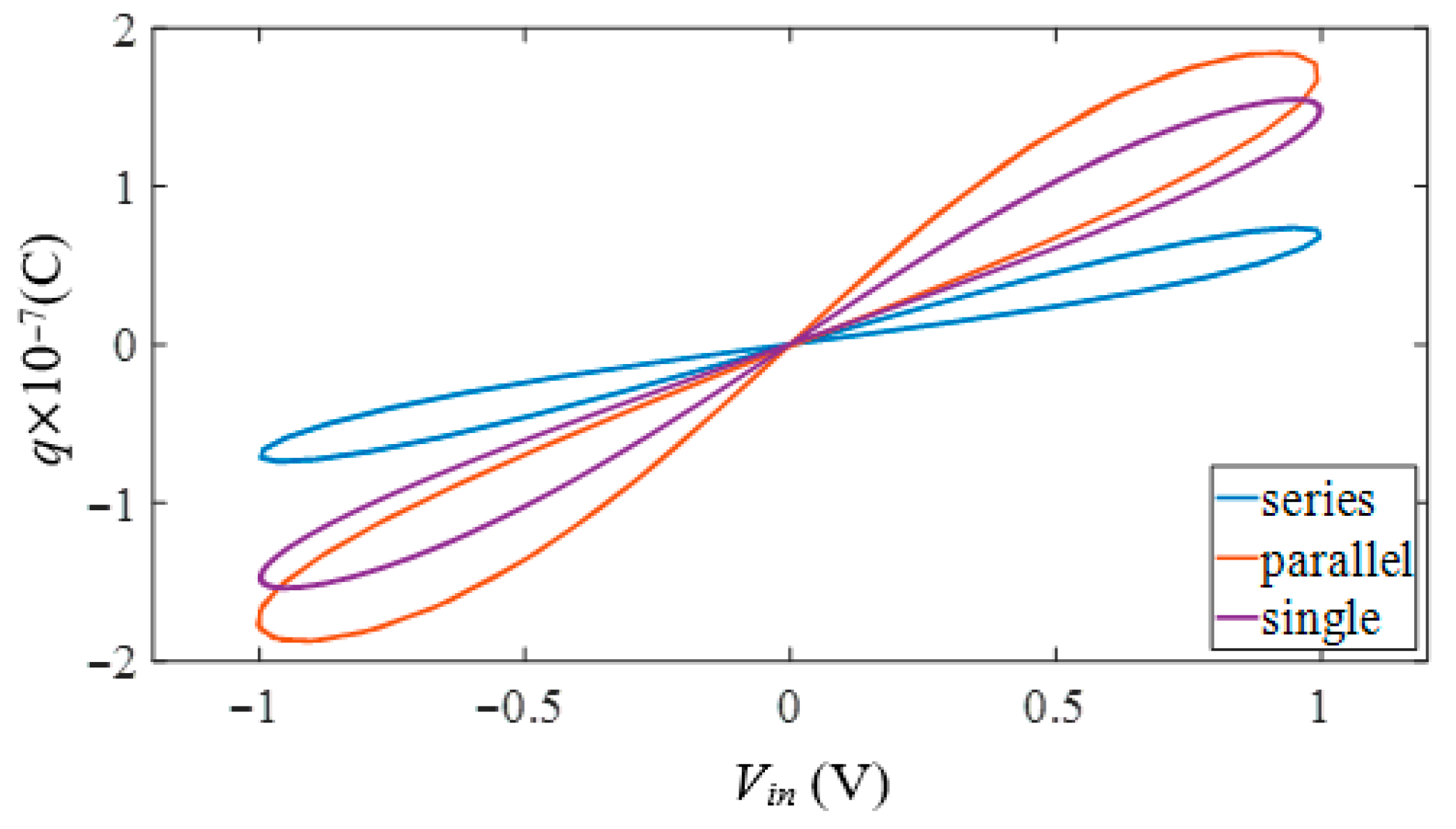
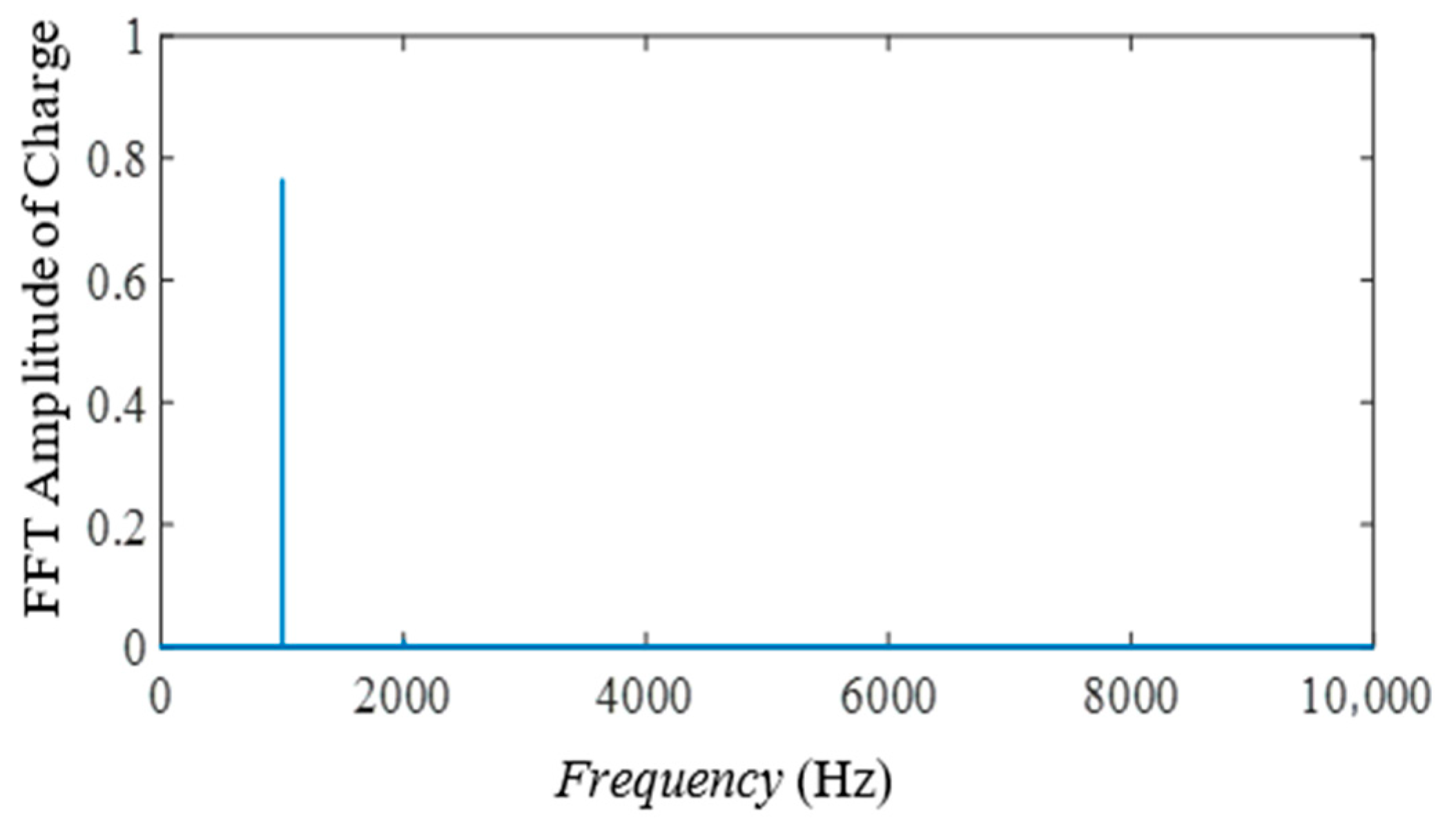
  • The designed memcapacitor emulator successfully passed the tests of non-volatility, frequency-dependent variable characteristics, series-parallel connection characteristics and Fourier analysis.
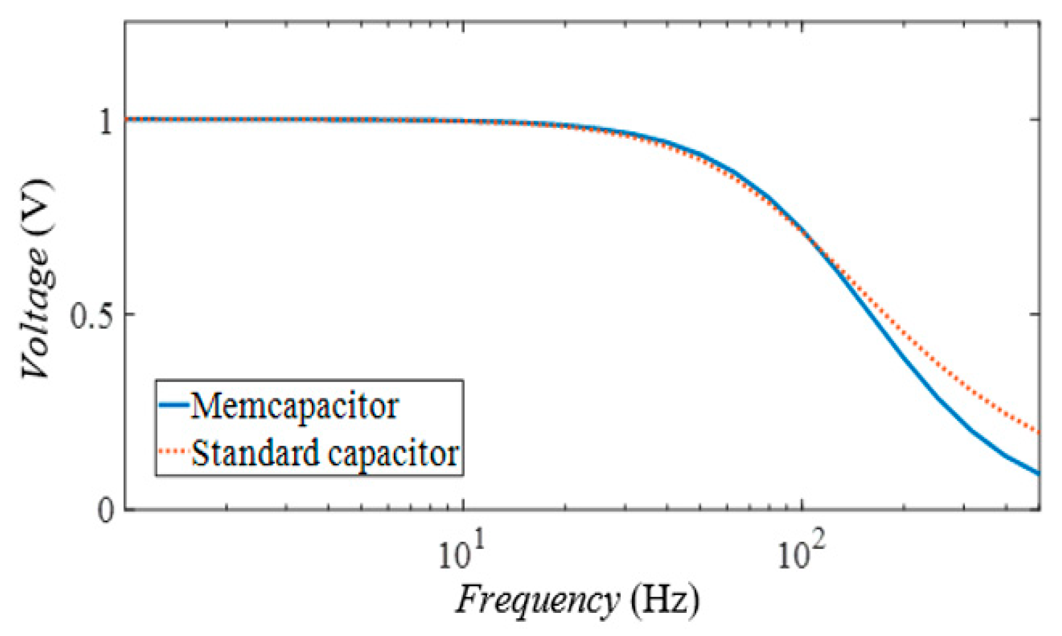
  • The proposed memcapacitor emulator circuit was implemented in a second-order active low-pass filter circuit and was found to be more efficient in both filtering performance and power consumption compared to the standard capacitor.
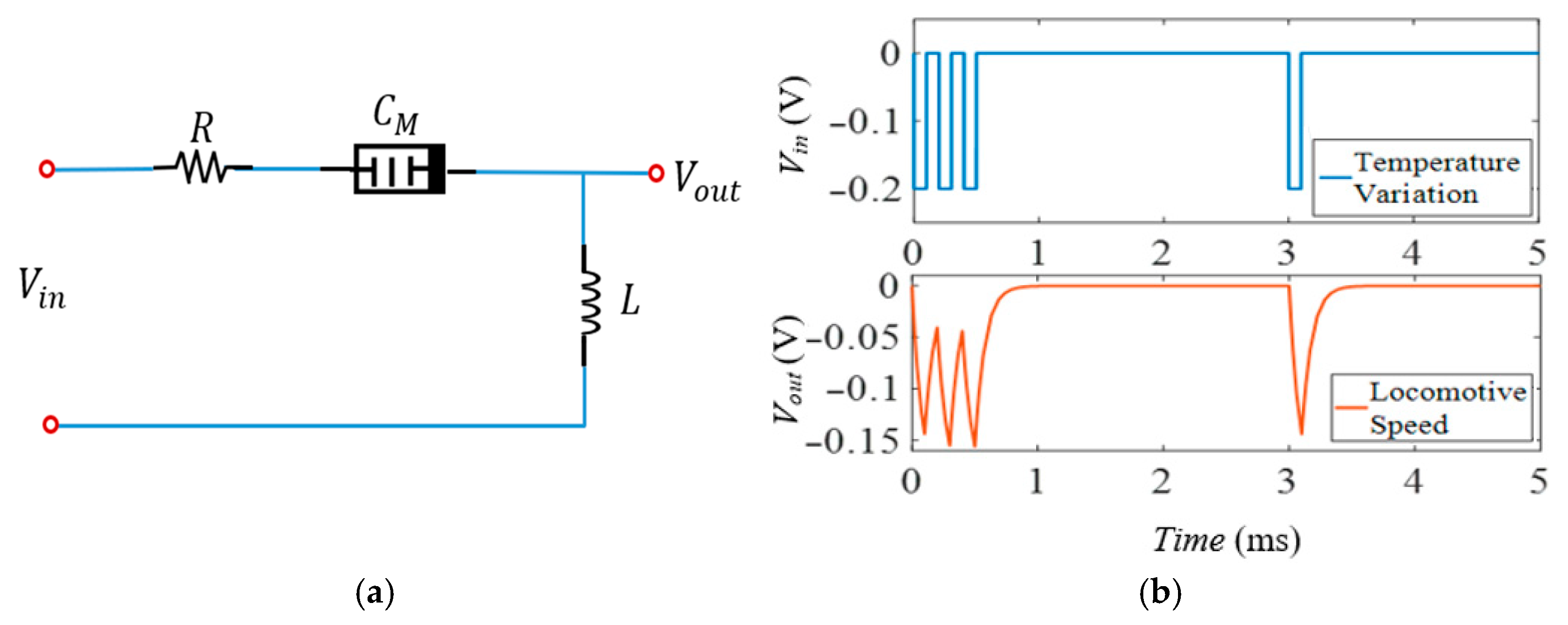
  • The proposed memcapacitor emulator also successfully completed the learning and data storage tasks in the amoeba learning circuit.
The rest of the paper is organized as follows. Section 2 presents the proposed memcapacitor emulator circuit and its analytical model. The performance analysis is given in Section 3 to demonstrate the characteristics of the emulator. In Section 4, the applications of memcapacitor emulator-based active filter circuit and amoeba learning circuits are analyzed. Some conclusions are given in Section 5.

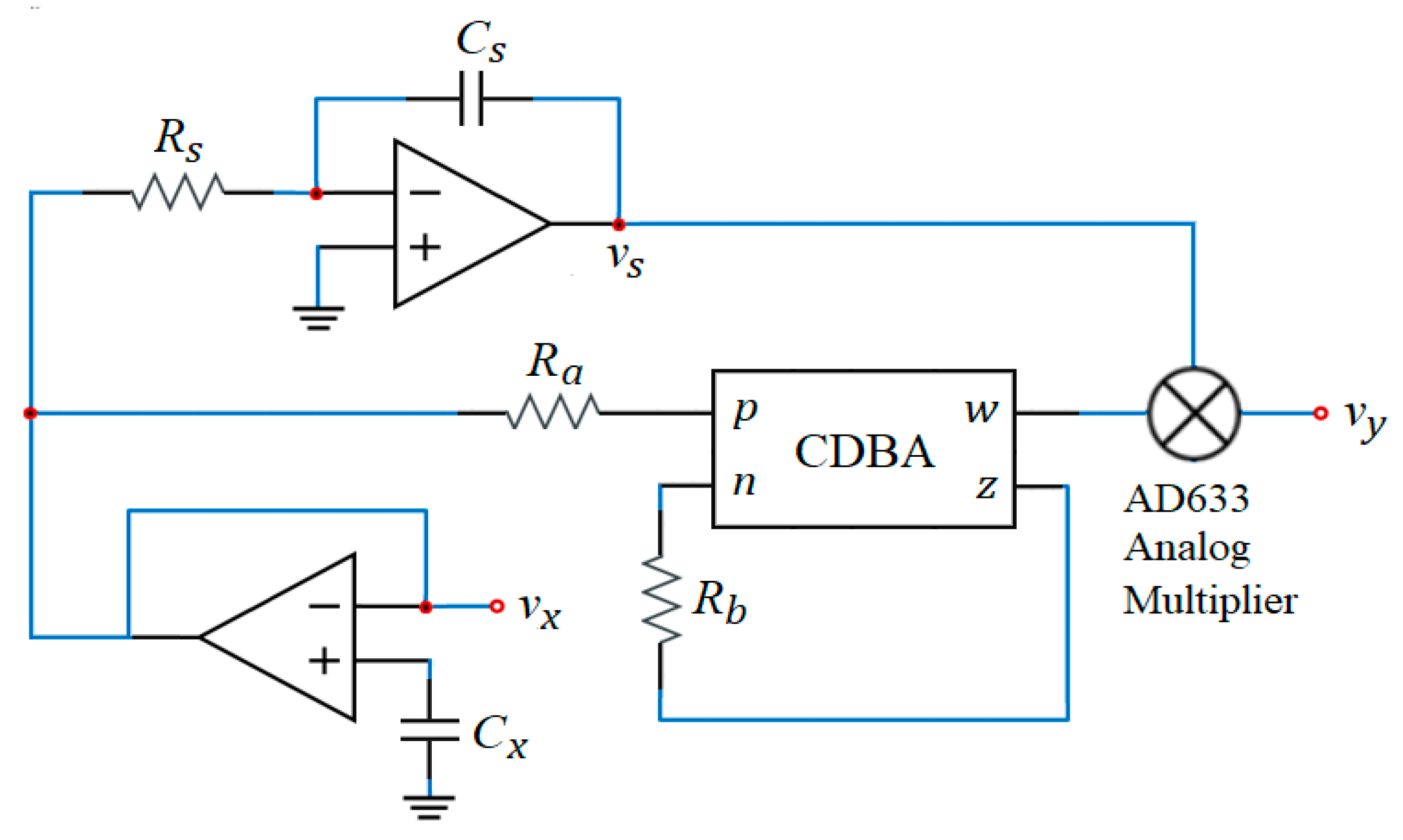
2. Proposed Memcapacitor Emulator Circuit

Classical circuit elements such as resistors, capacitors and inductors are expressed by the relationships between voltage, current, charge and flux, which are defined as fundamental electrical quantities. In contrast to these relationships, the definition of the memcapacitor is given by a relation of the form F φ , σ = 0 where φ and σ are the time integrals in ( , t ] of the voltage and charge, respectively. If this relation is expressible as a map σ φ   ( φ σ ) , the memcapacitor is said to be charge- (voltage-) controlled. By assuming that either map is differentiable, we can express the voltage in terms of the charge (or vice versa) in the form v = C M 1 σ q   ( q = C M φ v ) , where
C M 1 σ = v t q t = d φ d t d t d σ = d φ d σ ,
C M φ = q t v t = d σ d t d t d φ = d σ d φ .
Here, C M 1 σ is the inverse memcapacitance of the charge-controlled memcapacitor and C M φ is the memcapacitance of the voltage-controlled memcapacitor. This means that the quantity C M 1 σ   C M φ depends on the entire time history of the input variable. The memcapacitor therefore has a memory-dependent property and is an energy-storing electronic element [2,43]. Finally, in this work, we intend to design a charge-controlled memcapacitor emulator circuit that satisfies the following equation
v t = C M 1 t 0 t q τ d τ q ( t ) .
However, (3) is inadequate to express any parasitic effects and has no internal state vector. Instead, it is more realistic to use the expression given by
v t = α ± β σ t q t .
Here, α is the initial value of the memcapacitance and β represents the capacitance change corresponding to the charge flow in the memcapacitor, respectively [42,44].
In this section, a new memcapacitor emulator based on the CDBA is proposed. The CDBA, whose block diagram is shown in Figure 1, is implemented using two current feedback operational amplifiers, commercially available as AD844. The CDBA is an active element with four terminals that can be used in current and voltage mode analog signal processing circuits and filters. The p terminal of the CDBA is called the positive (non-inverting) input and the n terminal is called the negative (inverting) input. Both input terminals are virtually grounded, making them the preferred current inputs. The z terminal is a current output and the w terminal is a voltage output, which follows the voltage of the z terminal. The CDBA has low impedance inputs on the p and n terminals and a low impedance output on the w terminal. This allows it to be used as a cascadable active device [45]. The basic electrical descriptions of the terminals are expressed as follows
i z = i p i n ,   v p = v n = 0 ,   v w = v z .
Among these, the CDBA is notable for offering a balanced trade-off between performance and simplicity. It provides a wide bandwidth in the range of 10 100   M H z , moderate input-referred noise (approximately 20 80   n V / H z ), and low to moderate power consumption (typically 200 600   µ W ) [46,47]. Thanks to its differential current input and buffered voltage output, the CDBA enables easy cascading in current-mode systems without significant loading effects or signal degradation.
Although Operational Transconductance Amplifier (OTA) structures can achieve very low noise levels (as low as 10 50   n V / H z ) under optimized biasing conditions, they often suffer from limited linearity, narrow bandwidth (around 1 5   M H z ), and pronounced sensitivity to process, temperature, and voltage variations [48], which can compromise reliability in practical designs.
The (Current Buffered Transconductance Amplifier) CBTA and Current Differencing Transconductance Amplifier (CDTA) architectures enhance the CDBA by integrating a controllable transconductance stage (gm block) at the output, allowing electronic tuning of critical circuit parameters such as gain and cutoff frequency via an external control voltage or bias current. However, this added tunability comes at the cost of increased power consumption (typically 500 1200   µ W ), higher noise levels (ranging from 30 to 100   n V / H z ), and greater structural complexity [49].
The Second-Generation Current Conveyor (CCII) offers excellent high-frequency performance, often achieving bandwidths exceeding 100   M H z , with noise performance in the 40 100   n V / H z range. However, its lack of a current differencing input makes it less suitable for differential signal processing applications where the CDBA naturally excels [50].
In conclusion, the CDBA offers a compelling combination of robust high-frequency behavior, moderate noise, high slope speed, linear differentiation, buffer output capability low power requirements, and design simplicity [51,52,53]. These attributes make it a strong candidate for use in high-performance analog and mixed-signal circuits, especially where design stability and signal integrity are critical. Taking these benefits into account, a CDBA-based memcapacitor emulator circuit is proposed as shown in Figure 2. The emulator circuit consists of a CDBA, an integrator, an operational amplifier and some passive elements. The mathematical analysis of the emulator circuit can be given as follows:
The input voltage of the emulator circuit with the floating characteristic is defined as
v i n ( t ) = v x v y .
Here, v x is equal to the voltage across capacitor C x and is expressed by
v x = v C x = 1 C x t 0 t i C x d t = q ( t ) C x .
v y is the output of the four quadrant AD633 analog multiplier and is given by the equation
v y = ± α . v s . v w
where α = 1 / ( 10 Volt) as a property of the AD633 and v s is the integrator output. If the Y 1 terminal in the schematic of the AD633 is used, (8) takes a positive value, and if the Y 2 terminal is used, it takes a negative value. The current expression in (5) becomes i n = i p / 2 because i n is equal to i z due to the resistor R b in the emulator circuit. Therefore, the voltage of R b can be written in the form of
v R b = i n R b = i p R b 2 = v z = v w .
Since the voltage of R a is equal to v x and the current passing through R a is equal to i p , v w is stated as
v w = V x R b 2 R a .
The output of the integrator is
v s = 1 R s C s v x d t .
Taking into account (7), (11) becomes
v s = 1 R s C s C x t 0 t q t d t .
Since the integral of the charge in time is denoted by σ , (12) can be expressed simply as follows
v s = 1 R s C s C x σ t .
Using (10) and (13), the output of the analog multiplier in (8) is found as
v y = ± R b V x 20 R a R s C s C x σ t .
The input voltage of the memcapacitor emulator and its inverse memcapacitance are obtained as
v i n t = v x v y = q ( t ) C x 1 R b 20 R a R s C s C x σ ( t ) .
C M 1 = v i n ( t ) q ( t ) = 1 C x ± R b 20 R a R s C s C x 2 σ t .
As can be seen from (16), the inverse memcapacitance is a first-order polynomial function in the form of (4) with σ ( t ) as its variable. This structure, consisting of fixed and variable parts, facilitates the implementation of the emulator. Moreover, the fact that the variable part of (16) can be easily controlled by using resistors and capacitors is one of the important advantages of the proposed emulator. If the sign of the variable part in (16) is taken as negative, then the inverse memcapacitance has a decreasing characteristic, and in this case the element is referred to as an incremental memcapacitor. Conversely, for the inverse memcapacitance with an increasing characteristic, corresponding to the variable part with a positive sign, the element is defined as a decremental memcapacitor.
The physical behavior of the proposed memcapacitor emulator can be interpreted in analogy with existing models of memory-based circuit elements. Unlike traditional capacitors with a constant capacitance value, memcapacitors exhibit a charge-dependent dynamic capacitance show in (1), which encodes memory of past electrical activity. This property is given in (16) where the inverse memcapacitance C M 1 varies not only with a fixed base term 1 / C x , but also through a time-dependent modulation term involving the signal σ ( t ) . This additional term, scaled by passive elements such as R s , R b , R a , C s , C s implies that the effective capacitance is history-dependent. Such a structure parallels the physical analogies frequently employed in the literature; while a memristor is often likened to a deformable water pipe with resistance varying based on the history of current flow, a memcapacitor is analogously described as an elastic balloon whose stiffness changes depending on previous inflation cycles—that is, the amount of accumulated charge. Furthermore, the presence of the nonlinear term σ ( t ) introduces a dynamic hysteresis in the charge–voltage relationship, akin to pinched hysteresis loops observed in memcapacitive systems.
Since the realization of CDBA and analog multiplier with metal oxide semiconductor (MOS) transistors is well known in the literature, the proposed emulator is suitable for monolithic implementation in MOS transistor technology. Thus, it is possible to realize the integrated design of the proposed memcapacitor emulator using the MOS transistor models in [54,55] and obtain post-layout simulation results.

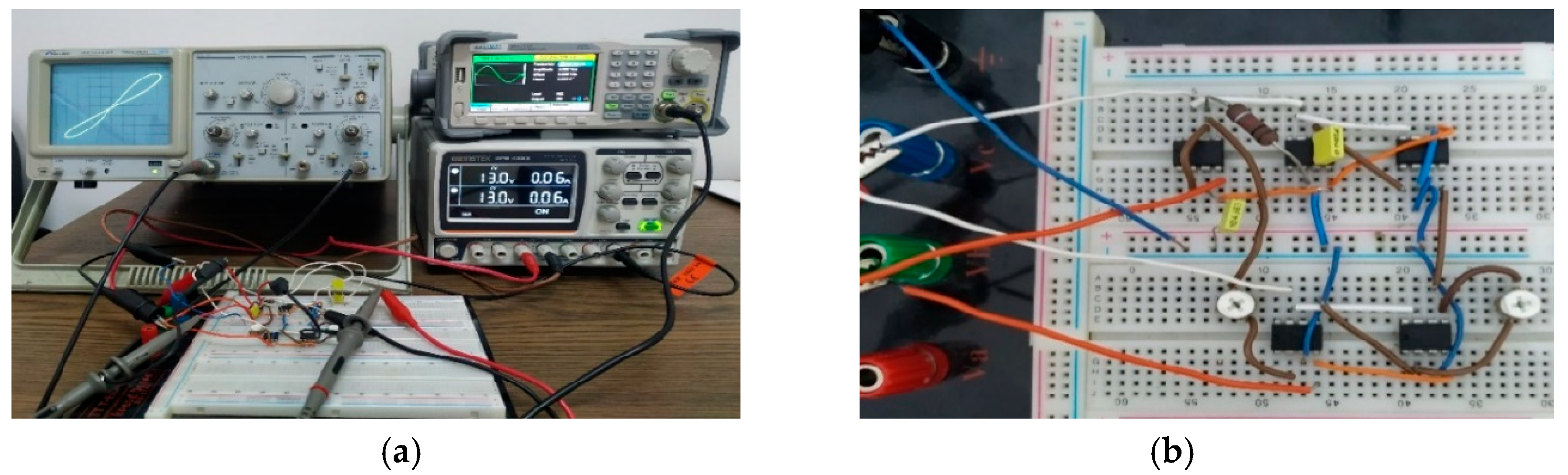
3. Simulation and Experimental Results

In order to confirm the theoretical results and demonstrate the feasibility and operating performance of the proposed memcapacitor, the emulator circuit in Figure 2 is simulated with Multisim program and also experimentally constructed with discrete circuit elements. The values of the passive elements for incremental and decremental memcapacitor emulators are R a = 60   k Ω , R b = 80   k Ω , R s = 1   k Ω , and C x = 100   n F . The value of C s for the incremental memcapacitor is taken as 220   n F , while this value is 70   n F for the decremental memcapacitor.
In this section, simulation results are given to investigate the voltage–charge characteristics, volatility behavior, electronic controllability and Fourier analysis of the emulator. These results are verified with the results of the emulator circuit built on breadboard using physical circuit elements as shown in Figure 3. All the elements used in the simulation circuit and the experimental circuit are the same. The CDBA element is obtained with AD844 opamps. The circuit can be considered quite simple, as shown in Figure 3b. The measurements were carried out with both digital and analog oscilloscopes. The digital oscilloscope used was a Unit UTD2052CL (UNI-TREND Technology EU GmbH, Augsburg, Germany), while the analog oscilloscope was a Twintex TOS-2020CH (Twintex, Dalmine, Italy).

3.1. Voltage–Charge Characteristics

The basic simulation results of the time responses of voltage and charge at 250   H z for incremental and decremental memcapacitor emulators are given in Figure 4. The figure shows that for a sinusoidal input voltage, the charge is seen as a sinusoidal signal with the peak shifted to the right in the incremental memcapacitor, and as a signal with the peak shifted to the left in the decremental memcapacitor. The voltage–charge characteristics of the incremental and decremental memcapacitor emulators are given in Figure 5. It is seen from the figure that the voltage–charge characteristics exhibit pinched hysteresis characteristics for the memcapacitor. Once it was demonstrated that the proposed memcapacitor provides basic memcapacitor properties for both the incremental and decremental memcapacitors, from this point onward, only results based on the incremental memcapacitor emulator will be given. Figure 6 shows the pinched hysteresis voltage–charge curves and its variation with frequency. This is one of the main characteristics of the memcapacitor element. As expected, the area enclosed by the hysteresis curve narrows with increase in frequency value. Furthermore, to verify that the memcapacitor is a variable element with operating frequency, the range of memcapacitance values with respect to the applied voltage is shown in Figure 7. As can be seen from this figure, the range of the memcapacitance value decreases with increasing frequency.
Experimental results confirming the simulation results in Figure 6 are shown in Figure 8a,b. Again, the hysteresis range in the voltage–charge characteristics narrows with increasing frequency. From (12), it is seen that the voltage v s is related to the memcapacitance charge and hence to the memcapacitance. Therefore, it can be seen in Figure 8c,d that the range of the v s voltage, and hence the memcapacitance, decreases with increasing frequency when the v s voltages at different frequencies are measured experimentally against the applied v i n voltages. This result indirectly confirms Figure 7 experimentally. Memcapacitor ranges calculated based on the obtained hysteresis curves are given in Table 1. The observed small differences between the simulation and experimental circuit results are mainly due to modeling ideality, physical parasitic effects, component tolerances and environmental conditions. While ideal conditions and component models are taken as a basis in simulation environments, real circuits are affected by various factors such as manufacturing variations, temperature changes, electromagnetic interference and measurement errors. In addition, the limited accuracy of the device models used and the ignoring of parasitic elements mean that the experimental results are not fully compatible. In our study, although the simulation and experimental applications are largely consistent, a small difference is observed due to the reasons listed above.
The proposed memcapacitor emulator may require connection in series or parallel in various electronic circuit applications. Therefore, a 300   H z , 1   V sinusoidal input signal was applied to single, series and parallel connected memcapacitors, and the resulting charge–voltage relationships were investigated. As expected, more capacitor charge values are obtained with memcapacitors connected in parallel than with those connected single and in series, as illustrated in Figure 9.

3.2. Non-Volatile Memory Property

Non-volatile memory technologies are an important feature for new generation electronic and computer systems. A non-volatile memory test is performed to demonstrate the memory feature of memcapacitor emulators. This test for the proposed memcapacitor emulator was performed by applying a pulse wave with 200   m V amplitude and 20 % pulse width to the input of the emulator. During each pulse, the memcapacitor charge follows the pulse as shown in Figure 10. When a pulse voltage is applied to the memcapacitor, the charge value increases and remains almost unchanged when the applied voltage is zero. An important feature is that when the pulse voltage is reapplied to the memcapacitor, the charge value continues to increase from the last value it took at the previous pulse value. As a result, the fact that the emulator circuit maintains the charge amount between two pulses proves that the proposed memcapacitor emulator has a non-volatile memory.
On the other hand, since this is an emulator circuit, small leakage currents are inevitable due to the active and passive elements used. If there is a very small change in the memcapacitor charge when the voltage applied to the circuit is interrupted and reapplied, this indicates a leakage current. In addition, by connecting 0   V DC voltage to the memcapacitor emulator, a leakage current of 53.8   p A was measured in the circuit. However, as can be seen from both Figure 10 and the leakage current test, the amount of leakage current is quite low.

3.3. Electronic Adjustability

Although it is an important feature of a memcapacitor emulator to be electronically adjustable, most of the emulators in the literature do not have this feature. The memcapacitor of the emulator proposed in this study can be tuned by changing the R b and C s values while the frequency value is fixed. For the 300   H z frequency value, the memcapacitance change ranges obtained by first changing the value of R b resistor and then C s capacitor are given in Figure 11. In addition, the electronic tunability feature is also examined experimentally and compared with the simulation in terms of quantitative values in Table 2 and Table 3. Although it is not possible to have one-to-one overlap of the quantitative results between the simulation and experimental applications considering the parameters such as tolerance values of the elements in the real world, sensitivity of the measurement instruments, etc., the results are quite consistent. The fact that the designed emulator provides electronically adjustable features by giving different memcapacitance ranges according to the change of element values in the circuit makes the proposed emulator stand out among those proposed in the literature.
The upper frequency limit of the memcapacitor emulator we designed is approximately 25   k H z . Obtaining the memcapacitive behavior at this frequency depends on the passive components in the emulator. In Table 4, while the values of the other passive components are kept constant, the value of the capacitor C s is changed to obtain different upper frequency limits. Thus, the operating range of the memcapacitor is considerably expanded, increasing its applicability in different applications.

3.4. Sensitivity Analysis

The sensitivity analysis of the memcapacitor emulator connected to passive elements has also been studied. For this, (17) expresses the sensitivity analysis according to the inverse memcapacitor in (16) and X represents each passive element to be analyzed, respectively. The general form of the sensitivity analysis performed separately for each passive element is available in Table 5. According to Table 5, the sensitivity analysis results of the C M 1 function show approximately how much C M 1 will change when the value of each element is increased by 1 % .
s x C M 1 = X C M 1 C M 1 X

3.5. Fourier Analysis

Fourier analysis is an important method widely used in fields such as signal processing and vibration analysis, and shows that any signal can be expressed as a series of sine waves with different amplitudes and phases [56]. In this section, a Fourier analysis was performed on the electrical charge in the memcapacitor corresponding to the designed emulator. According to the result of this analysis shown in Figure 12, the fundamental harmonic was observed at a frequency of 1   k H z , and the second harmonic was observed at a frequency of 2   k H z with very small amplitude. The total harmonic distortion (THD) in the memcapacitor was found to be 1.05 % at this frequency. The fact that the harmonics other than the fundamental harmonic are quite small supports this result. Since the memcapacitor charge signal is closer to the sinusoidal signal at high frequencies, it is normal for the Fourier analysis and the THD calculated accordingly to be quite low. As the frequency value decreases, the memcapacitor charge signal is a sinusoidal signal with a slope depending on the increasing or decreasing forms (since the q-v characteristic widens). Therefore, it is possible that the harmonics other than the fundamental harmonic are slightly more pronounced. This causes the THD at low frequencies to be slightly higher than the THD at high frequencies. In general, higher-order harmonics are not observed in the Fourier analysis due to the compressed charge–voltage relationship created by the emulator.
In order to examine the performance quality of our designed emulator and its contributions to the literature, the examination and comparison of current studies in the literature in terms of the parameters determining the performance quality are provided in Table 6 below. Compared to the memcapacitor emulator designs presented in the existing literature, the proposed circuit design exhibits a balanced performance in terms of circuit complexity, frequency response and practical applicability. Unlike circuits based solely on simulation data, our study has experimental data compatible with simulation. Some emulators have memristors in their structure or are designed with a large number of active elements, making them complex and costly; in this context, our emulator is at a medium cost. In addition, our circuit, which operates reliably up to approximately 25   k H z , offers higher performance than grounded or floating emulators that can only operate at lower frequency ranges. Moreover, it provides adaptability to various applications thanks to its electronically adjustable structure. This feature constitutes a significant advantage over studies that do not offer electronic control. All these features make the proposed emulator a powerful and applicable alternative for low and medium frequency analog memory applications.

4. Application Examples

4.1. Second-Order Active Low Pass Filter

In this section, in order to observe the performance of the proposed memristor emulator in a real circuit, a second-order active low-pass filter (2nd order active LPF) circuit is implemented as shown in Figure 13. In the circuit, instead of the standard capacitor with a value of 210   n F , a memcapacitor emulator with the same average memcapacitance value is used. The values of the other passive elements are R = 22   k Ω , R 1 = 10   k Ω and C 1 = 70   n F and the cut-off frequency of the filter circuit is f c = 1 / 2 π R C 1 = 103.34   H z . The effect of the memcapacitor on the circuit is analyzed and the results are compared. Figure 14 shows the voltage-frequency characteristics of the active low pass filter circuit when both the standard capacitor and the memcapacitor are used. It can be seen from Figure 14 that the low-pass filter with the memcapacitor is more effective than the standard capacitor filter in suppressing the signals. In order to verify this result, the filter circuit was implemented experimentally and it is seen in Figure 15a,b that the amplitude of the output voltage of the memcapacitor filter at a frequency of 300   H z is 0.23   V , while the amplitude of the standard capacitor circuit is 0.32   V . This finding indicates that the memcapacitor filter circuit exhibits more efficient filtering performance than the standard capacitor filter in the stopband.
A further analysis of the filter circuit involves the comparison of the reactive power value for the capacitor selected in the circuit. The reactive power values calculated using the formula Q = i 2 X c are Q C M = 10.84   μ V A R for the memcapacitor, and Q c = 15.04   μ V A R for the standard capacitor. This analysis indicates that the memcapacitor in the filter circuit consumes less reactive power than the standard capacitor and therefore has better performance in this respect. This real electrical circuit application demonstrates that the utilization of the recommended memcapacitor emulator in place of the standard capacitor yields more efficacious electrical results.

4.2. Amoeba Learning Circuit

The memory property of memcapacitors opens up a range of application areas in different electronic circuits. In this application, an RLC circuit containing a memory element is considered, which is used to electrically model the ability of amoeba-like cells to adapt their actions and change speed according to approaching stimuli such as temperature and humidity [44,60]. The series RLC circuit depicted in Figure 16a is subjected to a pulse signal with an amplitude of 200   m V as the input signal on three occasions in succession at 0.1   m s intervals and once after 3   m s . Figure 16b shows the graphs of the locomotive movement of the amoeba corresponding to the output signal for the temperature change corresponding to the input signal. As is evident from the figure, it is seen that the voltage corresponding to the locomotive speed decreases at each temperature drop point and the locomotive speed of the amoeba decreases gradually compared to the previous drop due to the decreasing temperature at the triple input signal. This result clearly demonstrates that the memcapacitor circuit has a learning and memory feature when a signal is applied more than once.

5. Conclusions

In this paper, an electronically tunable memcapacitor emulator circuit designed using CDBA element is presented both in mathematical analysis, simulation and experimental aspects. The development of technology has led to the increasing use of memristive elements in various scientific and technological fields. Mem elements, which are applied in many fields such as communication, neural networks, chaos, biology etc., are currently not available in the market as a commercial two-terminal element, which emphasizes the importance of designing better emulators to emulate them. The main advantages of the CDBA-based memcapacitor emulator proposed in this study are that it has a floating structure without grounding restriction, does not contain a memristor in its structure, has both incremental and subtractive forms and has an electronically tunable feature. The designed emulator has successfully passed the tests of frequency-dependent stepwise charge–voltage and memcapacitance-voltage characteristics, single-serial-parallel connection characteristics, non-volatility, Fourier analysis and electronic tunability. The performance of the proposed memcapacitor emulator was tested in two different electronic circuit applications and we found that it has the potential to provide significant advantages in various electronic applications. According to the measurement results, the memcapacitor emulator has 25 % better filtering ability and 27.93 % less power consumption compared to the standard capacitor in the low-pass filter circuit. In addition, the emulator effectively performs the learning and data storage functions in the amoeba learning circuit. It is thought that further studies on the proposed emulator circuit will make significant contributions to the literature by evaluating various electrical properties such as signal speed, power efficiency, chaotic signal generation, signal regulation, and investigating additional benefits.

Author Contributions

Conceptualization, S.G.K. and S.E.H.; methodology, S.G.K.; formal analysis, S.G.K. and Z.G.C.T.; investigation, S.G.K.; writing—original draft preparation, S.G.K.; writing—review and editing, S.G.K., Z.G.C.T. and S.E.H.; visualization, S.G.K. and Z.G.C.T.; supervision, Z.G.C.T. and S.E.H.; project administration, S.G.K., Z.G.C.T. and S.E.H. All authors have read and agreed to the published version of the manuscript.

Funding

This work is supported by the Inonu University Project of Scientific Research Unit (BAP) under the project number FDK-2022-3107.

Data Availability Statement

The original contributions presented in the study are included in the article, further inquiries can be directed to the corresponding author.

Conflicts of Interest

The authors declare no conflicts of interest. We declare that we do not have any commercial or associative interest that represents a conflict of interest in connection with the work submitted.

References

  1. Xiao, P.; Fang, J.; Wei, Z.; Dong, Y.; Du, S.; Wen, N.; Hong, Q. A Riccati Matrix Equation Solver Design Based Neurodynamics Method and Its Application. IEEE Trans. Autom. Sci. Eng. 2025, 99, 15163–15176. [Google Scholar] [CrossRef]
  2. Di Ventra, M.; Pershin, Y.V.; Chua, L.O. Circuit Elements with Memory: Memristors, Memcapacitors, and Meminductors. Proc. IEEE 2009, 97, 1717–1724. [Google Scholar] [CrossRef]
  3. Chua, L.O. Memristor—The Missing Circuit Element. IEEE Trans. Circuit Theory 1971, 18, 507–519. [Google Scholar] [CrossRef]
  4. Solovyeva, E.; Schulze, S.; Harchuk, H. Behavioral Modeling of Memristor-Based Rectifier Bridge. Appl. Sci. 2021, 11, 2908. [Google Scholar] [CrossRef]
  5. Xia, Z.; Sun, X.; Wang, Z.; Meng, J.; Jin, B.; Wang, T. Low-Power Memristor for Neuromorphic Computing: From Materials to Applications. Nano-Micro Lett. 2025, 17, 217. [Google Scholar] [CrossRef]
  6. Park, S.O.; Jeong, H.; Park, J.; Bae, J.; Choi, S. Experimental Demonstration of Highly Reliable Dynamic Memristor for Artificial Neuron and Neuromorphic Computing. Nat. Commun. 2022, 13, 2888. [Google Scholar] [CrossRef]
  7. Nirmal, K.A.; Kumbhar, D.D.; Kesavan, A.V.; Dongale, T.D.; Kim, T.G. Advancements in 2D Layered Material Memristors: Unleashing Their Potential Beyond Memory. npj 2D Mater. Appl. 2024, 8, 83. [Google Scholar] [CrossRef]
  8. Chen, Y.; Zhang, T.; Li, X.; Wang, Y.; Liu, J. Hardware Implementation of Memristor-Based Artificial Neural Networks. Nat. Commun. 2024, 15, 1234. [Google Scholar] [CrossRef]
  9. Sangwan, V.; Lee, H.S.; Bergeron, H.; Balla, I.; Beech, H.A.; Campbell, G.P.; Gong, Y.; Ajayan, P.M.; Lauhon, L.J.; Hersam, M.C. Multi-Terminal Memtransistors from Polycrystalline Monolayer Molybdenum Disulfide. Nature 2018, 554, 500–504. [Google Scholar] [CrossRef]
  10. Yu, F.; Zhang, S.; Su, D.; Wu, Y.; Gracia, Y.M.; Yin, H. Dynamic Analysis and Implementation of FPGA for a New 4D Fractional-Order Memristive Hopfield Neural Network. Fractal Fract. 2025, 9, 115. [Google Scholar] [CrossRef]
  11. Shooshtari, M.; Jiménez Través, M.; Pahlavan, S.; Serrano-Gotarredona, T.; Linares-Barranco, B. Applying Hodgkin–Huxley Neuron Model for Perovskite Memristor in Circuit Simulation. In Proceedings of the IEEE International Conference on Metrology for eXtended Reality, Artificial Intelligence and Neural Engineering (MetroXRAINE), Benevento, Italy, 5–7 June 2024; pp. 1077–1082. [Google Scholar] [CrossRef]
  12. Barraj, I.; Mestiri, H.; Masmoudi, M. Overview of Memristor-Based Design for Analog Applications. Micromachines 2024, 15, 505. [Google Scholar] [CrossRef]
  13. Dakheel, M.M.; Hassanein, A.M.; Fouad, R.A.; Radwan, A.G. Memristor-Based Data Converter Circuits. Electronics 2023, 12, 1654. [Google Scholar]
  14. Fahmy, G.A.; Zorkany, M. Design of a Memristor-Based Digital to Analog Converter (DAC). Electronics 2021, 10, 622. [Google Scholar] [CrossRef]
  15. Minati, L.; Gambuzza, L.V.; Thio, W.J.; Sprott, J.C.; Frasca, M. A Chaotic Circuit Based on a Physical Memristor. Chaos Solitons Fractals 2020, 138, 109990. [Google Scholar] [CrossRef]
  16. Duan, Z.; Chen, J.; He, S.; Yu, X.; Wang, Q.; Zhang, X.; Xiong, P. A Fully Integrated Memristive Chaotic Circuit Based on Memristor Emulator with Voltage Controlled Oscillator. Micromachines 2025, 16, 246. [Google Scholar] [CrossRef] [PubMed]
  17. Dong, C.; Yang, M. Extreme Homogeneous and Heterogeneous Multistability in a Novel 5D Memristor-Based Chaotic System with Hidden Attractors. Fractal Fract. 2024, 8, 266. [Google Scholar] [CrossRef]
  18. Qian, K.; Xiao, Y.; Wei, Y.; Liu, D.; Wang, Q.; Feng, W. A Robust Memristor-Enhanced Polynomial Hyper-Chaotic Map and Its Multi-Channel Image Encryption Application. Micromachines 2023, 14, 2090. [Google Scholar] [CrossRef]
  19. Hong, Q.; Jiang, H.; Xiao, P.; Du, S.; Li, T. A Parallel Computing Scheme Utilizing Memristor Crossbars for Fast Corner Detection and Rotation Invariance in the ORB Algorithm. IEEE Trans. Comput. 2025, 74, 996–1010. [Google Scholar] [CrossRef]
  20. Reynolds, J.; Lenz, G.; Tarigopula, A.; Green, D. A Scalable, Multi Core, Multi Function, Integrated CMOS/Memristor Sensor Interface for Neural Sensing Applications. Electronics 2025, 14, 30. [Google Scholar] [CrossRef]
  21. Chae, M.; Lee, D.; Kim, H.-D. Low-Power Consumption IGZO Memristor-Based Gas Sensor Embedded in an Internet of Things Monitoring System for Isopropanol Alcohol Gas. Micromachines 2024, 15, 77. [Google Scholar] [CrossRef]
  22. Odebowale, A.A.; Berhe, A.M.; Hattori, H.T.; Miroshnichenko, A.E. Modeling and Analysis of a Radiative Thermal Memristor. Appl. Sci. 2024, 14, 2633. [Google Scholar] [CrossRef]
  23. Biolek, D.; Biolek, Z.; Biolková, V. Coupled Memristors, Memcapacitors, and Meminductors and Their Fingerprints. AEÜ Int. J. Electron. Commun. 2018, 97, 263–266. [Google Scholar] [CrossRef]
  24. Biolek, D.; Biolek, Z.; Biolková, V. SPICE Modeling of Memristive, Memcapacitative and Meminductive Systems. In Proceedings of the European Conference on Circuit Theory and Design (ECCTD), Antalya, Turkey, 23–27 August 2009; pp. 249–252. [Google Scholar] [CrossRef]
  25. Di Ventra, M.; Pershin, Y.V. The Parallel Approach. Nat. Phys. 2013, 9, 200–202. [Google Scholar] [CrossRef]
  26. Wang, F.; Wang, F. Floating Memcapacitor Based on Knowm Memristor and Its Dynamic Behaviors. IEEE Trans. Circuits Syst. II Express Briefs 2022, 69, 5134–5138. [Google Scholar] [CrossRef]
  27. Liu, X.; Mou, J.; Wang, J.; Banerjee, S.; Li, P. Dynamical Analysis of a Novel Fractional-Order Chaotic System Based on Memcapacitor and Meminductor. Fractal Fract. 2022, 6, 671. [Google Scholar] [CrossRef]
  28. Wang, X.; Cao, Y.; Li, H.; Li, B. A Chaos-Enhanced Fractional-Order Chaotic System with Self-Reproduction Based on Memcapacitor and Meminductor. Fractal Fract. 2023, 7, 582. [Google Scholar] [CrossRef]
  29. Guo, M.; Yang, R.; Zhang, M.; Dou, G. A Novel Memcapacitor and Its Application in a Chaotic Circuit. Nonlinear Dyn. 2021, 105, 123–138. [Google Scholar] [CrossRef]
  30. Chen, G.; Yuan, F.; Dou, G.; Li, Y.; Wang, G. Complex Dynamics in a Memcapacitor-Based Chaotic Circuit. Entropy 2019, 21, 188. [Google Scholar] [CrossRef]
  31. Ishisaki, Y.; Oshio, R.; Kuwahara, T.; Shintani, M.; Tokumitsu, E.; Matsuda, T.; Kawanishi, H.; Nakashima, Y.; Kimura, M. Analog Memcapacitor by Ferroelectric Capacitor and Its Application to Spiking Neuromorphic System. IEEE Trans. Electron Devices 2024, 71, 4626–4630. [Google Scholar] [CrossRef]
  32. Van De Burgt, Y.; Melianas, A.; Keene, S.T.; Malliaras, G.G.; Salleo, A.; Tiberj, A.; Gerstner, W.; Zampieri, G.; Zenobi, G. Energy-Efficient Memcapacitor Devices for Neuromorphic Computing. Nat. Electron. 2021, 4, 740–747. [Google Scholar] [CrossRef]
  33. Hossain, R.; Mohamed, A.S.; Armendarez, N.X.; Najem, J.S.; Hasan, M.S. Biomembrane-Based Memcapacitive Reservoir Computing System for Energy Efficient Temporal Data Processing. arXiv 2023, arXiv:2305.12025. [Google Scholar] [CrossRef]
  34. Singh, A.; Kim, D.; Lee, B.-G. Analysis of a Memcapacitor-Based Neural Network Accelerator Framework. arXiv 2025, arXiv:2502.00027. [Google Scholar] [CrossRef]
  35. Zhang, Z.; Pershin, Y.V.; Martin, I. Electromechanical Memcapacitive Neurons for Energy-Efficient Spiking Neural Networks. arXiv 2023, arXiv:2304.10899. [Google Scholar] [CrossRef]
  36. Min, J.; Kang, S.; Kim, S. Memcapacitor-Based Minimum and Maximum Logic Gate Design. In Proceedings of the 2021 18th International SoC Design Conference (ISOCC), Jeju Island, Republic of Korea, 6–9 October 2021; pp. 1–4. [Google Scholar]
  37. Tran, D.; Teuscher, C. Memcapacitive Devices in Logic and Crossbar Applications. arXiv 2017, arXiv:1704.05921. [Google Scholar] [CrossRef]
  38. Cam Taskiran, Z.G.; Sagbas, M.; Ayten, U.E.; Sedef, H. A New Universal Mutator Circuit for Memcapacitor and Meminductor Elements. AEÜ Int. J. Electron. Commun. 2020, 119, 153180. [Google Scholar] [CrossRef]
  39. Sharma, P.K.; Ranjan, R.K.; Khateb, F.; Kumngern, M. Charge Controlled MEM-Element Emulator and Its Application in a Chaotic System. IEEE Access 2020, 8, 171397–171407. [Google Scholar] [CrossRef]
  40. Yesil, A.; Babacan, Y. Electronically Controllable Memcapacitor Circuit with Experimental Results. IEEE Trans. Circuits Syst. II Express Briefs 2021, 68, 1443–1447. [Google Scholar] [CrossRef]
  41. Ananda, R.Y.; Satyanarayan, G.S.; Trivedi, G. A High Frequency MOS-Based Floating Charge-Controlled Memcapacitor Emulator. IEEE Trans. Circuits Syst. II Express Briefs 2023, 70, 1189–1193. [Google Scholar] [CrossRef]
  42. Vista, J.; Ranjan, A. Simple Charge Controlled Floating Memcapacitor Emulator Using DXCCDITA. Analog Integr. Circuits Signal Process. 2020, 104, 37–46. [Google Scholar] [CrossRef]
  43. Corinto, F.; Civalleri, P.P.; Chua, L.O. A Theoretical Approach to Memristor Devices. IEEE J. Emerg. Sel. Top. Circuits Syst. 2015, 5, 123–132. [Google Scholar] [CrossRef]
  44. Korkmaz, M.O.; Babacan, Y.; Yesil, Y. A New Floating Memcapacitor Emulator Circuit without Using Passive Elements. Int. J. Circuit Theory Appl. 2024, 52, 3650–3663. [Google Scholar] [CrossRef]
  45. Acar, C.; Ozoguz, S. A New Versatile Building Block: Current Differencing Buffered Amplifier Suitable for Analog Signal Processing Filters. Microelectron. J. 1999, 30, 157–160. [Google Scholar] [CrossRef]
  46. Ozoguz, S.; Toker, A.; Ibrahim, M.A. A New Versatile Building Block: Current Differencing Buffered Amplifier and Its Applications. In Proceedings of the 1999 European Conference on Circuit Theory and Design (ECCTD’99), Stresa, Italy, 29 August–2 September 1999; pp. 1187–1190. [Google Scholar]
  47. Biolek, D.; Senani, R.; Biolková, V.; Kolka, Z. Active Elements for Analog Signal Processing: Classification, Review, and New Proposals. Radioengineering 2008, 17, 15–32. [Google Scholar]
  48. Wilson, B. Recent Developments in Current Conveyors and Current-Mode Circuits. IEE Proc. G Circ. Devices Syst. 1990, 137, 63–77. [Google Scholar] [CrossRef]
  49. Ayten, U.E.; Sagbas, M.; Sedef, H. Current Mode Leapfrog Ladder Filters Using a New Active Block. Int. J. Electron. Commun. (AEÜ) 2010, 64, 503–511. [Google Scholar] [CrossRef]
  50. Sedra, A.S.; Smith, K.C. A Second-Generation Current Conveyor and Its Applications. IEEE Trans. Circ. Theory 1970, 17, 132–134. [Google Scholar] [CrossRef]
  51. Oner, S.E. Design of Active Filters Using a New Active Device CDBA. Master’s Thesis, Council of Higher Education, Ankara, Turkey, 2007. [Google Scholar]
  52. Ozcan, S.; Toker, A.; Acar, C.; Kuntman, H.; Cicekoglu, O. Single Resistance-Controlled Sinusoidal Oscillators Employing Current Differencing Buffered Amplifier. Microelectron. J. 2000, 31, 169–174. [Google Scholar] [CrossRef]
  53. Kaewpoonsuk, A.; Petchmaneelumka, W.; Kamsri, T.; Riewruja, V. Realization of OTA-Based CDBA. In Proceedings of the International Conference on Control, Automation and Systems (ICCAS), KINTEX, Bucheon, Republic of Korea, 2–5 June 2005. [Google Scholar]
  54. Borah, S.S.; Sundaravadivel, P. A Review of Current Differencing Buffered Amplifiers: Performance Metrics and Technological Advances. Electronics 2024, 13, 3623. [Google Scholar] [CrossRef]
  55. Babacan, Y. Ultra-Low Voltage and Low-Power Voltage-Mode DTMOS-Based Four-Quadrant Analog Multiplier. Analog Integr. Circuits Signal Process. 2019, 99, 39–45. [Google Scholar] [CrossRef]
  56. Kaya, Z. Implementation of Fast Fourier Transform on Programmable Gate Arrays. Ph.D. Thesis, Council of Higher Education, Ankara, Turkey, 2021. [Google Scholar]
  57. Yu, D.; Zhao, X.; Sun, T.; Iu, H.H.C.; Fernando, T. A Simple Floating Mutator for Emulating Memristor, Memcapacitor, and Meminductor. IEEE Trans. Circuits Syst. II Express Briefs 2020, 67, 1334–1338. [Google Scholar] [CrossRef]
  58. Korkmaz, M.O.; Yeşil, A. FDCCII Tabanlı, Elektronik Olarak Ayarlanabilir Yeni Bir Memkapasitör Emülatör Devresi. Mühendis. Bilim. Ve Araştırmaları Derg. 2023, 5, 127–134. [Google Scholar] [CrossRef]
  59. Pershin, Y.V.; Di Ventra, M. Emulation of Floating Memcapacitors and Meminductors Using Current Conveyors. Electron. Lett. 2011, 47, 243–244. [Google Scholar] [CrossRef]
  60. Korkmaz, M.O.; Babacan, Y.; Yesil, A. Mutator Circuit for Memcapacitor Emulator Using Operational Transconductance Amplifiers. Elektron. Ir Elektrotechnika 2024, 30, 38402. [Google Scholar] [CrossRef]
Figure 1. Internal structure of the CDBA.
Applsci 15 07506 g001
Figure 2. Schematic diagram of the proposed CDBA-based memcapacitor emulator circuit.
Applsci 15 07506 g002
Figure 3. Experimental implementation of the proposed memcapacitor emulator: (a) experimental platform, (b) breadboard circuit diagram.
Applsci 15 07506 g003
Figure 4. Voltage and charge time responses of the memcapacitor emulator circuits: (a) incremental, (b) decremental.
Applsci 15 07506 g004
Figure 5. The voltage–charge characteristics of the memcapacitor emulator circuits: (a) incremental, (b) decremental.
Applsci 15 07506 g005
Figure 6. The voltage–charge characteristics at different operating frequencies.
Applsci 15 07506 g006
Figure 7. The voltage-memcapacitor characteristics at different operating frequencies.
Applsci 15 07506 g007
Figure 8. Experimental characteristics between q v i n and between v s v i n at different frequencies: (a) 125   H z   ( q v i n ) , (b) 750   H z   ( q v i n ) , (c) 125   H z   ( v s v i n ) , (d) 750   H z   ( v s v i n ) .
Applsci 15 07506 g008
Figure 9. Voltage–charge characteristics of the memcapacitor emulator in single, series and parallel configurations.
Applsci 15 07506 g009
Figure 10. V p u l s e - q values obtained for non-volatile testing of the designed emulator.
Applsci 15 07506 g010
Figure 11. Voltage–charge characteristics of memcapacitor electronically controlled by (a) R b , (b) C s .
Applsci 15 07506 g011
Figure 12. Fourier analysis of the memcapacitor emulator.
Applsci 15 07506 g012
Figure 13. Second-order active LPF circuit with memcapacitor.
Applsci 15 07506 g013
Figure 14. Filter frequency characteristics for standard capacitor and memcapacitor.
Applsci 15 07506 g014
Figure 15. Experimental output voltages of 2nd order active LPF circuit with (a) standard capacitor, (b) memcapacitor at 300 Hz.
Applsci 15 07506 g015
Figure 16. (a) Amoeba’s learning circuit using memcapacitor emulator ( R = 1   k and L = 1   m H ). (b) Response of the amoeba’s learning application.
Applsci 15 07506 g016
Table 1. Memcapacitance ( C M ) ranges obtained for different frequencies.
FrequencyCm Range
With SimulationWith Experiment
125   H z 80 310   n F 80 260   n F
250   H z 110 295   n F 100 235   n F
500   H z 140 280   n F 125 210   n F
750   H z 165 250   n F 130 205   n F
Table 2. Memcapacitance ( C M ) ranges obtained for different C s values.
Parameters C s C M Range Simulation C M Range Experimental
R s = 1   k Ω
R b = 80   k Ω
R a = 60   k Ω
C s = 100   n F
140   n F 110 300   n F 110 285   n F
220   n F 118 245   n F 115 225   n F
300   n F 120 220   n F 120 210   n F
Table 3. Memcapacitance ( C M ) ranges obtained for different R b values.
Parameters R b C M Range Simuation C M Range Experimental
R s = 1   k Ω
R a = 60   k Ω
C s = 100   n F
C w = 220   n F
70   k Ω 120 235   n F 123 208   n F
80   k Ω 118 285   n F 115 260   n F
90   k Ω 116 340   n F 110 290   n F
Table 4. The upper frequency limit of the memcapacitor emulator according to the C s .
Parameters C s Upper Frequency Limit
R s = 50   Ω
R b = 80   k Ω
R a = 100   k Ω
C x = 100   n F
20   n F 15   k H z
10   n F 20   k H z
5   n F 25   k H z
Table 5. Sensitivity analysis of memcapacitor emulator.
P a r a m e t e r s Sensitivity Analysis
R s −1
R b 1
R a −1
C s −1
C x −2
Table 6. Performance comparison of memcapacitor emulator.
Ref.ComponentsComplexityFrequency PerformanceFloating/GroundedSim/Exp.Electronic ControlCost
[40]2 CCII,
1 AM 1 R, 3 C
Medium 2   k H z GroundedSimulation ExperimentalYesMedium
[41]1 VDTA,1 OTA,1 buffer, 1 R, 2 CMedium ~ 1.2   M H z FloatingSimulation ExperimentalNoMedium
[57]4 CCII, 1 Opamp, 1 Varactor Diode, 6 R, 2 C High 8   k H z FloatingSimulation ExperimentalNoHigh
[58]1 FDCCII, 1 AM, 2 MOSFETs, 3 CMedium 1   M H z GroundedSimulation OnlyYesMedium
[59]4 CCII, 1 Memristor, 1 L1 RHighNot specifiedFloatingSimulation OnlyNoHigh
This study1 CDBA, 2 opamp, 1 AM, 3 R, 2 CMedium ~ 25   k H z FloatingSimulation ExperimentalYesMedium
Disclaimer/Publisher’s Note: The statements, opinions and data contained in all publications are solely those of the individual author(s) and contributor(s) and not of MDPI and/or the editor(s). MDPI and/or the editor(s) disclaim responsibility for any injury to people or property resulting from any ideas, methods, instructions or products referred to in the content.

