Article

Energy-Environmental Analysis of Retrofitting of a Chilled Water Production System in an Industrial Facility—A Case Study

Institute of Environmental Engineering and Building Installations, Poznań University of Technology, Berdychowo St. 4, 60-965 Poznań, Poland
*
Author to whom correspondence should be addressed.
Appl. Sci. 2025, 15(13), 7465; https://doi.org/10.3390/app15137465
Submission received: 29 May 2025 / Revised: 26 June 2025 / Accepted: 30 June 2025 / Published: 3 July 2025

Abstract

This paper presents a method of evaluating energy and environmental factors before and after chilled water production system retrofitting at an industrial facility. A general algorithm was used for the analysis of chilled water system retrofitting at a pharmaceutics factory. Two retrofitting variants based on dual-stage absorption chillers supplied from an existing gas-fueled co-generation plant were identified. The proposed variants, i.e., tri-generation systems, were compared with the basic variant, which relied on electric compression water chillers. An evaluation of the variants was performed on the basis of two criteria: annual primary energy consumption and annual carbon dioxide emission. Variant 2, i.e., with a 1650 kW dual-stage absorption water chiller supplied from an existing gas fueled co-generation plant, was chosen as the optimal variant. It achieved a 370 MWh annual primary energy consumption reduction and a 1140 Mg annual carbon dioxide emission reduction. It was found that increasing the co-generation ratio for the CHP plant powering the pharmaceutical factory resulted in lower consumption of primary energy in variants in which the cooling energy supply system was retrofitted based on absorption water chillers. The threshold values of the co-generation ratio were e = 0.37 for Variant 1 and e = 0.34 for Variant 2. A literature survey revealed that there is limited interest in the application of such a solution in industrial plants. The performed analysis showed that the evaluated systems may nonetheless be an attractive option for pharmaceutics factories, leading to the reduction of primary energy consumption and carbon dioxide emissions, thereby making more electrical power available for core production. The lessons learned during our analysis could be easily transferred to other industrial facilities requiring chilled water production systems.

1. Introduction

The demand for cooling energy in the form of chilled water is an important factor when considering energy management in many industrial plants. In most cases, the basic devices used for chilled water production are compression chillers with air-cooled condensers (monoblock-type) or water-cooled condensers (split-type). Using electricity to power the production of cooling energy limits core production, which requires electricity to power new processing lines. Replacing the above-mentioned systems with absorption units powered by hot water or steam, which are already available in many industrial plants, may therefore be an attractive alternative.
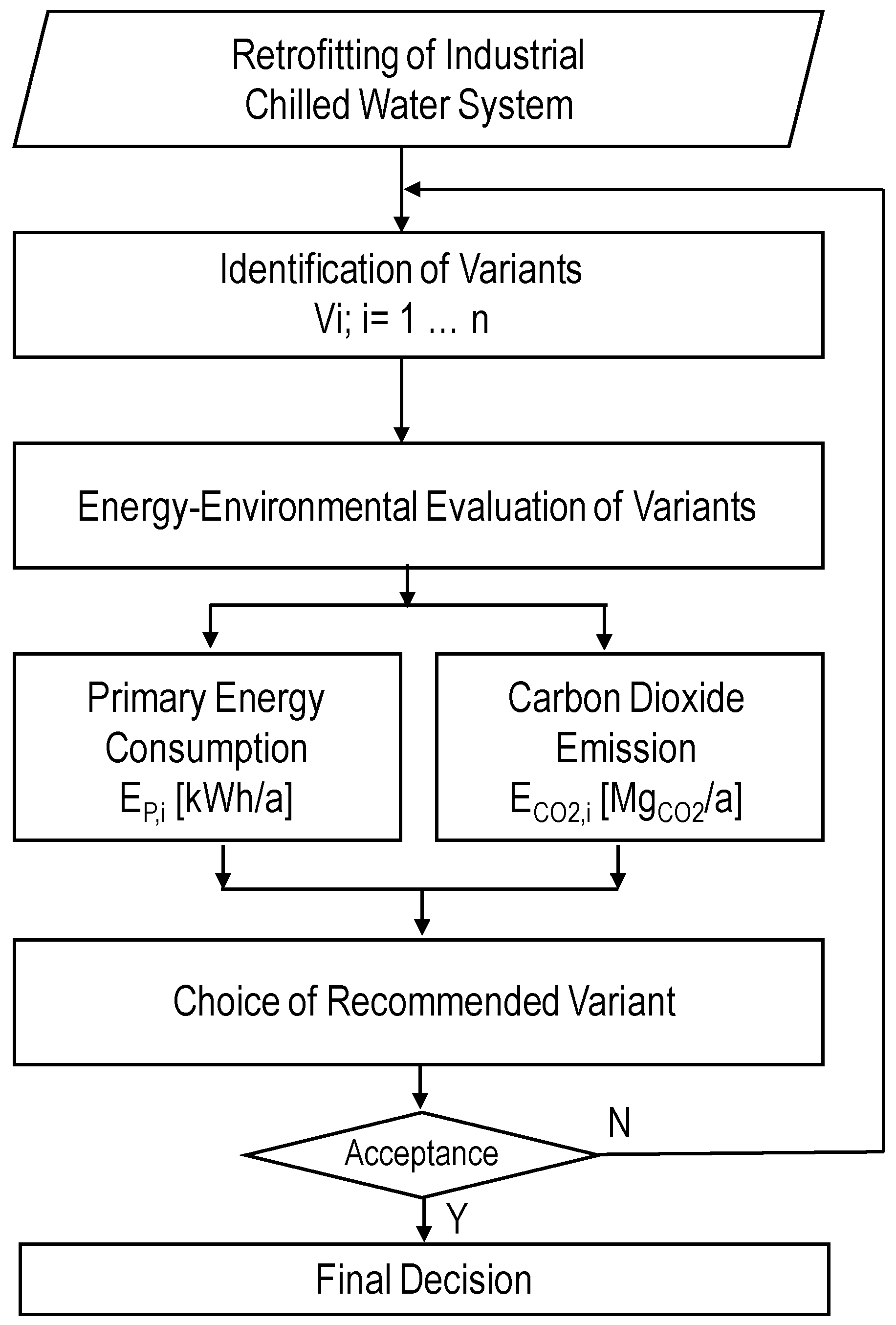
In order to select the variant of expansion or retrofitting of a chilled water production system, one needs to conduct an analysis taking into account the cooling needs, their variation over time, and the availability of energy carriers. The identified variants should be assessed according to multiple criteria, taking into account technological, energy-related, environmental, and economic aspects.
A review of absorption cooling technologies that may be applied in chilled water systems in industrial plants can be found in Nikbakhti et al. [1]. The authors noted an increased interest in this field in connection with the energy crisis, rise in primary fuel prices, and the negative environmental impact of traditional compression chilling systems. They noted that despite its many advantages (e.g., the possibility of using low-potential heat as a power source, and using cooling mediums with minimal environmental impact), this technology is characterized by low energy efficiency. By analyzing research by many other authors, they pointed to options in terms of improving the energy efficiency ratio (EER) and seasonal energy efficiency ratio (SEER) by increasing heat recuperation, using new pairs of mediums, and modifying the operating parameters.
Many research papers on absorption technology are concerned with evaluations and possible improvements of energy efficiency.
Kaynakali et al. [2] performed an energy and exergy analysis of a dual-stage absorption system powered by various energy sources. While studying the application of hot water, steam, and hot air as energy sources for a high-temperature boiler, they noticed that the internal exergy losses were lowest when the boiler was fueled by hot water and highest when it was fueled by hot air.
Saoud et al. [3] conducted in situ research and numerical modeling of a single-stage absorption chiller. Those authors built a numerical model of the chiller based on the energy balance, which they validated against a commercially available, 106.1 kW water chiller. By analyzing the device’s EER, cooling efficiency, and temperature drop in the boiler, they concluded that the equipment operated correctly across a broad range of boiler-powering temperatures and enabled the efficient use of low-temperature sources of powering heat.
El-Shafie et al. [4] conducted experimental research on a 1750 kW absorption chiller with a natural gas-fueled boiler. Two years of research allowed those authors to determine the energy-efficiency variability and internal exergy losses of the device based on operating time. They noticed a 22% drop in the EER and a 14% increase in exergy losses, which they attributed to the device becoming contaminated during use. Their final conclusion was that the equipment should undergo service checks more frequently.
Mróz (2006) [5] conducted experimental research on a 500 kW single-stage absorption chiller fueled by steam. The research helped to evaluate the energy and economic efficiency of the studied system. It was discovered that the instantaneous cooling load of the device significantly influenced its EER.
The prospects for integrating absorption chilling systems as elements of a combined energy economy were described in [6,7,8].
Trygg and Amiri [6] noted that Sweden offers favorable conditions for implementing absorption technology using waste heat from electricity generation in heat and power plants. They calculated that applying tri-generation technology may result in an 80% national-scale reduction in carbon dioxide emissions and a 170% reduction in the costs of cooling energy generation as a result of the sale of electricity generated in this way.
A similar analysis of the Finnish energy market was conducted by Saastamoinen and Paiho [7], who noted the attractiveness of using tri-generation systems.
Gąsiorowski and Mróz [8] analyzed the energy and exergy efficiency of a low-power tri-generation system based on a gas-fueled microturbine and a single-stage absorption chiller. They demonstrated that in such systems, the key parameter impacting efficiency is the optimal use of waste heat, i.e., the heat of the exhaust gases generated in the gas microturbine.
From the point of view of synergy between absorption chillers and combined heat and power (CHP) systems, another important parameter is the required temperature of the heat vector supplied to the boiler. Gomari et al. [9] studied the influence of supply temperature on the EER in single-, dual- and three-stage absorption systems. They found that the maximum EER value for a typical vaporization temperature (Tv = 4 °C) was 95 °C for single-stage systems (EER = 0.7), 190 °C for dual-stage systems (EER = 1.2), and 205 °C for three-stage stage systems (EER= 1.6). The rising required temperature of boiler power supply negatively impacted the operation of CHP production, resulting in a lower co-generation ratio.
M.M. Joybari and F. Haghighat [10] conducted an analysis of systems with various heat exchanger designs, all sharing the same EER coefficient. Their study on the effects of the working fluid’s mass flow rate and the inlet temperatures of the cooling water, chilled water, and heating fluid from the heat source showed that a decrease in the working fluid’s mass flow rate resulted in reduced exergy loss for the system element in question. Additionally, they observed that the total system exergy rose when the heat source and inlet chilled water temperatures were lower and the inlet cooling water temperature was higher. The analysis found that the absorber and condenser experienced the most significant exergy losses. Consequently, the studies recommended modifying the cooling tower by decreasing the cooling water’s mass flow rate while increasing its temperature, ensuring that it can still satisfy cooling demand.
In an article by H. Ansarinasab and others [11], a thermoeconomic analysis of a solar-powered absorption cooling system integrated with different types of collectors was presented. Their analysis revealed that the system performance factor increased with an increase in source temperature and evaporator temperature, while the exergy efficiency was proportional to the temperature of the water supplying the generator and inversely proportional to the temperatures of the evaporator, absorber, and condenser. It was pointed out that the most economical solution from the perspective of exergy efficiency was a solar absorption cooling system utilizing evacuated tube collectors (ETC), with an exergy efficiency of 0.66. However, when interpreting the system efficiency data, the use of parabolic trough collectors (PTCs) proved to be the most favorable solution.
Kerme et al. [12] conducted a series of studies and analyses on an absorption cooling system using lithium bromide and water, powered by solar energy (flat plate collector). Aspects including the impact of different types of collectors on efficiency and heat gain, the inlet temperature to the generator, the efficiency of the heat exchanger, and the mass flow rate of the working fluid were assessed to determine their influence on system performance. The analysis indicated that using a collector with a selective coating increased the system’s efficiency and heat gain compared to using single- or double-glazed collectors. An increase in the heat exchanger efficiency significantly improved the overall system performance, while increasing the mass flow rate of the fluid reduced the chiller efficiency. The results showed that the main source of exergy losses in this system was the solar collector (which accounted for 84% of the total exergy losses), followed by the generator (8.3% of the total exergy losses). Increasing the inlet temperature to the generator led to a slight increase in cooling efficiency, but after stabilizing, it ultimately decreased. This also resulted in increased exergy losses in system components. Based on these findings, the authors noted that improving the heat exchanger efficiency reduced the exergy losses of the system and improved the cooling performance, while an increase in the mass flow rate led to a decrease in the efficiency of the system, contributing to higher exergy losses.
In his article, G. S. Dhindsa [13] presented actions aimed at improving the performance of absorption cooling systems powered by solar energy. The author noted that the use of various types of waste energy led to a significant increase in the efficiency of the absorption cooling system. That article also highlighted the correlation between system performance and the increased latent heat of the working fluid. Attention was drawn to the beneficial effect of using iron oxide nanoparticles as a component of the refrigerant fluid. G.S. Dhindsa emphasized that under optimal operating temperatures for the generator, a constant pressure process demonstrated higher absorption cooling efficiency than a constant temperature process.
G. L. Szabó [14] examined ways to optimize the operation of absorption chillers for cooling purposes, with the main requirement being the increase in exergy efficiency, which impacts both quantitative and qualitative indicators. The article stated that ways to improve system performance included changing the generator temperature, changing the condensation temperature, and consolidating changes in both the generator and condenser temperatures. For example, lowering the condenser temperature by 2.1 °C and increasing the generator temperature by 27.3 °C significantly increased the system performance indicators.
In an article by J. Asadi and others [15], a thermoeconomic analysis of a solar-powered absorption cooling system integrated with different types of collectors was presented. The analysis found that the system performance factor increased with an increase in the source temperature and the evaporator temperature, while the exergy efficiency was proportional to the temperature of the water that supplied the generator and inversely proportional to the temperatures of the evaporator, absorber, and condenser. A solar absorption cooling system using evacuated tube collectors (ETC) was identified as the most economically favorable solution, with an exergy efficiency of 0.66. However, in terms of the efficiency of the solar-powered system, the use of parabolic trough collectors (PTC) turned out to be the most beneficial.
Banua and Sudharsanb [16] conducted a thermodynamic analysis of absorption cooling systems. They demonstrated that choosing the right device parameters, such as the type of working fluid and the number of stages of the device, plays a crucial role in improving the efficiency of absorption cooling systems, which can be aided by the use of thermodynamic analyses (TDA). The article highlighted the optimal temperature ranges for generators based on the COP values of devices with a specific number of stages and configurations.
Rashidi and Yoo [17] compared the KPCC system (using the Kalina cycle with an NH3-H2O absorption chiller) and the KLACC system (using the Kalina cycle with a LiBr-H2O absorption chiller). The analysis showed that exergy losses in the KLACC system were 40% higher (mainly in the condenser and the preheater of the second separation tank). As a result, the efficiency of this system was close to the Kalina cycle’s efficiency, while the efficiency of the KPCC system was 6.8% higher. From an economic analysis perspective, the unit cost of energy production in the KPCC system was 20.5% lower than in the KLACC system. The analysis also emphasized that efforts to reduce exergy losses should focus on the absorber in KPCC systems and the second condenser in KLACC systems.
Alazwari et al. [18] analyzed the operation of an absorption chiller in an air handling unit with heat recovery using phase change materials (PCM) on building partitions. The authors investigated the benefits of the improvements made to the basic configuration of the system. The use of PCM reduced the cooling energy demand by 6.22%, while heat recovery reduced the demand by 8.38%. The total reduction in energy consumption generated by these improvements was approximately 111 kWh/m2. The study concluded that for cases with high cooling demand, it is worth analyzing the implementation of such improvements, especially when there is no possibility of using larger cooling-producing equipment.
In [19], the economic and environmental costs of using of a device based on solar energy-powered absorption cooling was analyzed and compared to those of a standard inverter device with a heat pump. Those others found that absorption cooling devices used in Australia consume at least 50% less energy than inverter air conditioners, resulting in half the CO2 emissions. Additionally, absorption chillers consume approximately 75% less peak electrical power (kWp), which is particularly important given the increasing performance issues affecting the power grid. However, due to the significantly higher capital cost of solar-powered absorption chillers, with a long payback time exceeding 20 years, the use of such systems, despite their numerous benefits, is difficult to justify.
Kheiri et al. [20] analyzed a gas turbine-based trigeneration system (GTBS) utilizing waste gasification fuel, which produces electricity and heat that may be used by absorption chillers to produce cooling. It was found that during the winter period, the energy utilization factor of such a device was 47.62% and its exergy efficiency was 20.42%. An environmental analysis showed that the use of the GTBS system reduced potential CO2 emissions of 9233 tons annually. Further parametric studies conducted by those authors indicated that increasing the gasifier temperature and the inlet gas temperature to the gas turbine increased the energy utilization factor of the device while reducing its exergy efficiency and overall system operating costs.
Nondy and Gogoi [21] compared the optimal performance of two gas turbine-based CCHP trigeneration systems: the first, consisting of a steam turbine, a Rankine regenerative cycle with heat recovery, two stages of absorption cooling, and a water heater, and the second, in which the Rankine regenerative cycle was replaced by a steam turbine condensation cycle. Based on a parametric analysis, the optimization of these systems resulted in a slight improvement in energy and exergy efficiency, while the device costs were reduced by 9% and 5.3%, respectively. With such a configuration, the payback time was found to be 10.83 years for the first system and 13.27 years for the second. Furthermore, it was found that under optimal operating conditions, the overall energy production and efficiency of the systems were nearly identical, but the overall cost of the first system was significantly lower than that of the second. In addition, the first system exhibited the lowest specific CO2 emissions, i.e., 91.75 kg/MWh.
In [22], a new CCHP system powered by biogas was proposed, based on secondary exhaust gas injection (due to high exergy losses in systems based on chemical recovery). Huang and other authors noted that the new system would feature an increased methane conversion factor. In the new system, electricity production increased by 55.52 kW (corresponding to 6.2%) and cooling increased by 542.49 kW (corresponding to 101.49%). The analysis revealed that the exergy efficiency of the system increased by 8.31%. The study indicated that an excessive inlet temperature of the gas to the turbine was unfavorable for exergy efficiency from the perspective of the whole system.
Mirzaee and other authors [23] analyzed a co-generation system modeled in the EES software (Aspen Plus), consisting of a gas turbine, absorption chiller, boiler, and heat exchanger. The system was studied under nine characteristic scenarios and the results were presented and compared in terms of energy efficiency, energy consumption, fuel consumption ratio, and CO2 production. The optimal solution for combined electricity and cooling production was found in Scenario 5 (two absorption chillers installed in series, i.e., Stages I and II), with a fuel consumption ratio of 45,325.5 kJ/kg. For the combined production of electricity and heat, Scenario 7 was the most beneficial (with a fuel consumption ratio of 39,541.9 kJ/kg), where all heat could be recovered. That article also noted that the highest CO2 production (88.18 kg/s) was observed in the devices presented in Scenarios 1 and 6, which were found to be insufficient and inefficient. On the basis of the conducted studies, it was concluded that for combined heat and electricity production, reducing the pressure in the heat recovery system of the gas turbine led to a decrease in the output temperature from the heat exchanger, significantly affecting the fuel consumption ratio.
Modi et al. studied the energy efficiency of a single-stage absorption chiller with variable parameters in terms of boiler power supply and absorber cooling [24]. They showed that the decreasing absorption temperature increased the device’s energy efficiency, i.e., the possibility of cooling the absorber to 30 °C allowed for the maximization of the EER (0.77) when the boiler’s supply temperature was lowered to 82 °C. Similar research results were obtained by Karamangil et al. [25], Sun [26], and Aphornratana and Sriveerakul [27].
A literature survey revealed that there is limited interest in the application of such solutions in industrial plants. This is partly due to a lack of knowledge among industry energy managers concerning the availability of absorption cooling technologies. New approaches to the evaluation of industrial plants based on the Environmental-Social-Governance (ESG) model require a broader look at existing, technically acceptable solutions which could help to reduce energy consumption and the environmental footprint of industry.
Despite relatively low EERs and SEERs, absorption chillers used in synergy with combined heat and power sources—i.e., tri-generation systems—may be attractive solutions in terms of energy usage (primary energy) and environmental sustainability (CO2 emissions) in comparison to traditional compressor systems powered by electricity.
Here, we present an energy and environmental analysis of implementing the dual-stage absorption chillers supplied from an existing gas-fueled co-generation plant at a selected pharmaceutical plant. It is proposed that such an action may lead to the reduction of primary energy consumption and carbon dioxide emissions.

2. Evaluation Method

In order to evaluate chilled water retrofitting variants, the energy-environment method was proposed. The general algorithm of the proposed method is shown in Figure 1.
The identification of technically acceptable variants was based on an analysis of available chilled water production technologies and access to energy carriers, e.g., electricity, hot water, low pressure, or high pressure steam. We also required detailed information about cooling load and annual cooling energy use of the studied industrial plant.
Our evaluation of the identified variants included two decision criteria: annual primary energy consumption and annual carbon dioxide emissions.
Our calculation of annual primary energy consumption was based on the annual cooling energy use and energy efficiency of chilled water production systems, including the seasonal energy efficiency ratio (SEER) of water chillers and overall energy efficiency of the production and distribution of the energy carriers used to drive water chillers. The derivation of annual carbon dioxide emissions requires knowledge on primary energy carbon dioxide emission factors depending on the ratio of the carbon content in the fuel and its low heating value. The detailed calculation procedure for both decision criteria is described in Section 4.

3. Case Study—Description of Variants

3.1. Basic Solution—Variant 0

The total cooling power of the cooling energy receivers installed in the studied pharmaceutical plant amounted to 4600 kW. The total cooling power of the cooling energy sources present in the facility equaled 3635 kW, which constituted 78% of the total cooling power of all receivers. The entire amount of the 7/15 °C chilling water produced in the plant was used for cooling and drying the air in the air conditioning systems in the technological area and for cooling the air in the office area and auxiliary production area (i.e., control rooms, server rooms, CCTV rooms).
The planned development and modernization of the chilling water production system assumed an increase of cooling power to 4085 kW, with the technological structure of the source to be as follows:
  • CHCh1—compression chiller with in-built condenser; planned chiller with 1000 kW cooling power (EER = 3.03, SEER = 3.85),
  • CWCh3—compression chiller; existing chiller with 635 kW cooling power,
  • CWCh4—compression chiller with in-built condenser; planned chiller with 650 kW cooling power (EER = 2.99, SEER = 3.85),
  • CWCh5—compression chiller; existing chiller with 900 kW cooling power,
  • CWCh6—compression chiller; existing chiller with 900 kW cooling power
Each of the above-listed chillers was connected to a joint 2xDn350 chilling water collector via an individual pipe connection equipped with a hydraulic control system, i.e., a set of throttles. Said collector powered a hydraulic loop supplying chilling water to all receivers located in the facility.
An additional element of the planned modernization of the plant’s cooling source was a free cooling system equipped with two dry air coolers, DC1 and DC2, with 1200 kW maximum cooling power (operating with external temperatures below 0 °C).
A schematic of the basic solution (Variant 0) for chilled water system retrofitting is shown in Figure 2.
The planned modernization of the chilled water production system in the facility did not change the cooling economy there. The economy was still meant to be based on compression water chillers powered by electricity. In addition, the chillers used, with integrated air-cooled condensers, had relatively low EERs and SEERs. Consequently, one would expect a slight drop in the consumption of primary energy and a small drop in the carbon dioxide emissions of the plant.
However, this situation could change by using dual-stage, steam-powered absorption water chillers (AWChs). The source of power of a dual-stage AWCh is high pressure steam.
The facility under study is equipped with a natural-gas fueled, back-pressure combined heat and power plant. The total production capacity for 10 bar steam is 9.6 Mg/h, with 6.4 Mg/h being used continuously by the facility for technological purposes. The remaining steam production capacity of the CHP plant (3.2 Mg/h) is a reserve that can be used to power dual-stage absorption water chillers.
The average annual energy efficiency of the CHP plant (production and transmission) is ηEC = 0.875, and the average annual heat production co-generation ratio in the form of steam and electricity e = 0.41.
Based on the verified balance of cooling needs and the proposed scenario for chilled water source modernization, two variants of cooling energy supply to the facility were proposed, employing dual-stage, absorption water chillers—Variants 1 and 2. Both variants involved the installation of new water chillers with total cooling capacity of 1650 kW.

3.2. Variant 1

The first variant replaced the planned 1000 kW compression water chiller CWCh1 with a dual-stage absorption water chiller with equivalent cooling power. It used deionized water as a refrigerant and a lithium bromide (LiBr) water solution as the absorbent. The refrigerant, i.e., water vapor, flowed from evaporator to the absorber due to the pressure difference. The resulting decrease of lithium bromide concentration necessitated the regeneration of absorbent, which was directed to the generator. A schematic of the proposed variant of system retrofitting is shown in Figure 3. The source was equipped with a dual-stage 1000 kW AWCh paired with an open-type cooling tower. The technical characteristics of the setup described in this variant are given in Table 1.
The implementation of Variant 1 required: (i) the development of a steam and condensate network from the steam CHP plant to the absorption water chiller room adjacent to the production building; (ii) the development of a steam connection station to the absorption water chiller with an automatic regulation system; (iii) the development of a service water network connecting the water chiller with the open cooling tower; and (iv) the development of a network supplying the cooling water volume in the system, along with a treatment station.
Other elements of the system were in line with the accepted basic variant of modernization for a chilled water system. A schematic of the connections of the 1.0 MW dual-stage absorption water chiller is shown in Figure 4 [28].

3.3. Variant 2

The second variant assumed replaced the two planned compression water chillers—CWCh1 (1000 kW cooling power) and CWCh4 (650 kW cooling power)—with a dual-stage absorption water chiller with 1650 kW cooling power. It used deionized water as a refrigerant and a lithium bromide (LiBr) water solution as the absorbent. The refrigerant, i.e., water vapor, flowed from evaporator to the absorber due to the pressure difference. The resulting decrease of lithium bromide concentration necessitated the regeneration of absorbent, which was directed to the generator. A schematic of the proposed variant of system retrofitting is shown in Figure 5. The absorption water chiller operated in synergy with the open-type cooling tower. The technical characteristics of the setup described in this variant are given in Table 2.
The implementation of Variant 2 required: (i) the development of a steam and condensate network (or modification of the existing network) from the steam CHP plant to the absorption water chiller room adjacent to the production building; (ii) the development of a steam connection station to the absorption water chiller with an automatic regulation system; (iii) the development of a service water network connecting the water chiller with the open cooling tower; and (iv) the development of a network supplying the cooling water volume in the system, along with a treatment station.
Other elements of the system were in line with the accepted basic variant for the modernization of the chilled water system. A schematic of the connections of the 1.65 MW dual-stage absorption water chiller is shown in Figure 6 [28].

4. Energy and Environmental Evaluation of the System Retrofitting Variants

4.1. Annual Cooling Energy Production

Based on information obtained from the chilled water receiver monitoring system at the facility, it was assumed in the annual cooling energy demand analysis that the system’s peak demand for cooling power would amount to 78% of the maximum power needs of the installed receivers, i.e., 3635 kW [29]. The entire amount of the chilled water produced was used to maintain the thermal comfort parameters in the production area (air cooling and drying) and in the office and auxiliary area (air cooling).
The expected annual cooling energy consumption was calculated according to the guidelines on energy certification for water chillers. Assuming that the operation time of the water chillers in the facility covered the period from 15 April to 15 September, i.e., 3600 h/a, and in the remainder of the year, the cooling needs were wholly met by the slow cooling system, the amount of the cooling energy produced in a year would correspond to the values presented in Table 3 [29].
Assuming that the production of cooling energy in the absorption water chillers would account for the core production, and the compression chillers would supply the supplementary and peak production, the annual supply of cooling energy from the absorption chillers would be as follows [29]:
  • Variant 1—1000 kW maximum power, operation for 3600 h/a, 3600.0 MWh/a,
  • Variant 2—1650 kW maximum power, operation for 3600 h/a, 4620.0 MWh/a
The designated volumes of cooling energy production were used to compare the consumption of primary energy and carbon dioxide emissions for the proposed retrofitting variants with reference to the basic variant.

4.2. Annual Consumption of Primary Energy

From the point of view of implementing a sustainable energy management strategy, it was necessary to optimize the consumption of non-renewable energy vectors—i.e., to minimize primary energy consumption and reduce carbon dioxide emissions. In order to compare the effects of implementing, in the considered plant, a chilled water production system based on absorption water chillers with a traditional system based on compression water chillers powered by electricity, we calculated the consumption of primary energy and carbon dioxide emissions. The comparison was made exclusively with reference to the retrofitted part of the chilled water production system.
In the case of the basic variant (Variant 0), the consumption of primary energy was calculated as follows:
E P = 1 η TOT , 0 Q ch , r SEER 0
where:
EP-annual consumption of primary energy for the purpose of producing cooling energy, in MWh/a,
Qch,r-annual cooling energy production, in MWh/a,
SEER0-seasonal energy efficiency ratio for a compression water chiller,
ηTOT,0-total efficiency of electricity production, transmission, and utilization.
The total efficiency of the production, transmission, and utilization of the electricity vector in the case of compression water chillers was calculated as follows:
η TOT , 0 = η EL η W
where:
ηEL-efficiency of electricity production and transmission in the Polish energy system, i.e., 0.40,
ηW-efficiency of energy utilization in the facility, i.e., 1.00.
In the case of Variants 1 and 2, the consumption of primary energy was calculated according to the avoided cost principle [30], making it possible to compare the consumption of primary energy in cogenerative circuits (CHP plants) and separate ones (the production of heat in heating plants and electricity in system power stations). In line with the above, the consumption of primary energy for Variants 1 and 2 could be calculated as follows:
E P = 1 η TOT , 1 2 Q ch , r SEER 1 2 1 + e 1 η TOT , 0 Q ch , r SEER 1 2 e
where:
EP-annual consumption of primary energy for the purpose of producing cooling energy, in MWh/a,
Qch,r-annual cooling energy production, in MWh/a,
SEER1(2)-seasonal energy efficiency ratio for an absorption water chiller,
ηTOT,1(2)-total efficiency of steam production, transmission, and consumption in the CHP plant in the facility.
e-average annual electricity and heat co-generation ratio in the facility’s CHP plant.
The average annual electricity and heat co-generation ratio in a facility’s CHP plant is an average annual measure of efficiency that indicates the amount of electricity produced relative to the amount of useful heat generated in the co-generation process.
e = E Q
where:
E-the amount of electricity produced, in MWh/a,
Q-the amount of useful heat produced, in MWh/a,
Ratio (e) indicates how many units of electricity are produced per unit of useful heat generated in the co-generation process.
The total efficiency of the production, transmission, and consumption of the electricity vector in the case of compression water chillers was calculated as follows:
η TOT , 1 2 = η EC η W
where:
ηEC-efficiency of production and transmission of steam from the facility’s CHP plant, i.e., 0.875,
ηW-efficiency of steam utilization in the facility, i.e., 0.96.
The annual consumption of primary energy for the production of cooling energy, as calculated using the aforementioned procedure, is compared in Table 4, with Variant 0 being the system modernization variant based on compression water chillers.
According to Table 4, the best variant of chilled water production system modernization in the pharmaceutical plant was Variant 2, in which the core production of cooling energy was performed by a 1.65 MW steam-powered dual-stage absorption water chiller. This variant allowed for a reduction in the consumption of primary energy of over 370 MWh/a (12.3%) compared to the basic variant. In the case of Variant 1, the main reason for its higher consumption of primary energy than in Variant 0 was the constant operation of the compression water chiller generating 1020 MWh of cooling energy—resulting in annual consumption of over 660 MWh/a of primary energy. Despite this, even this solution enabled a reduction in primary energy consumption of over 170 MWh/a (5.6%) compared to the basic variant.
The consumption of primary energy in the system retrofitting variants based on absorption water chillers was strongly influenced by the electricity and steam co-generation ratio in the CHP plant powering the pharmaceutical factory. Figure 7 illustrates this influence for a constant efficiency of energy supply from the CHP plant equal to 0.84.
An increasing co-generation ratio for the CHP plant powering the pharmaceutical factory resulted in lowering the consumption of primary energy in variants of retrofitting the cooling energy supply system based on absorption water chillers. On the other hand, when this ratio dropped to e = 0.30, the variants became less attractive than the basic variant.
The threshold values of the co-generation ratio for which the variants based on absorption water chillers displayed primary energy consumption at the level of the basic variant were e = 0.37 for Variant 1 and e = 0.34 for Variant 2.

4.3. Annual Emissions of Carbon Dioxide

Another important parameter in the evaluation of sustainable energy management is the level of carbon dioxide emissions. The annual carbon dioxide emissions for the basic variant of chilled water production in the pharmaceutical plant could be calculated as follows:
E CO 2 = e CO 2 WK E P , 0
where:
ECO2-annual CO2 emissions connected with producing cooling energy for the basic variant, in MgCO2/a,
EP-annual consumption of primary energy for the purpose of producing cooling energy, in MWh/a,
e CO 2 WK -carbon dioxide emission ratio for a given primary fuel in the basic variant (coal) e CO 2 WK = 0.35 MgCO2/MWh.
In Variants 1 and 2, the annual carbon dioxide emissions were derived from Equation (7), again applying the principle of avoided cost:
E CO 2 = 1 η TOT , 1 2 Q ch , r SEER 1 2 1 + e e CO 2 GZ 1 η TOT , 0 Q ch , r SEER 1 2 e e CO 2 WK
where:
EP-annual consumption of primary energy for the purpose of producing cooling energy, in MWh/a,
e CO 2 GZ -carbon dioxide emission ratio from primary fuel used in variants based on absorption water chillers (natural gas) e CO 2 GZ = 0.20 MgCO2/MWh.
The annual carbon dioxide emissions stemming from cooling energy generation in the pharmaceutical plant were calculated according to Equation (7) and are compared in Table 5.
According to Table 5, the application of absorption water chillers as the core source of cooling energy production in the pharmaceutical plant would allow for a significant reduction of carbon dioxide emissions to the atmosphere. Compared to system modernization based on compression water chillers (Variant 0), annual CO2 emission related to chilled water production could be reduced by over 900 Mg/a (in the case of Variant 1) and 1140 Mg/a (in the case of Variant 2). The negative CO2 emissions in Variant 2 were due to both the application of the avoided cost principle, which greatly reduced primary energy consumption, and replacing coal with natural gas, which has a much lower index of carbon dioxide emissions per unit.
The analysis of primary energy consumption and carbon dioxide emissions led us to the recommend the implementation of Variant 2, i.e., the installation of a 1.6 MW dual-stage absorption water chiller.

5. Conclusions

The performed energy-environmental analysis of the retrofitting of a chilled water production system in a pharmaceutical facility led us to formulate the following conclusions:
  • The realization of cooling energy management in the considered industrial facility, based on covering core cooling needs using energy produced in steam-powered dual-stage absorption water chillers, is a viable solution.
  • The two variants under analysis consisted of replacing the planned electric-powered compression water chillers. The proposed solutions based on double-stage absorption water chillers would help to significantly reduce the consumption of primary energy and the emission of carbon dioxide related to the production of cooling energy.
  • Despite the absorption water chillers having much lower energy efficiency ratios (EERs) and seasonal energy efficiency ratio (SEERs) than commonly used compression water chillers, employing steam co-generated with electricity to power them makes them more attractive from the point of view of energy consumption and environmental impact.
  • It was found that co-generated heat and power plant energy efficiency and co-generation ratio were of the greatest importance concerning the reduction of primary energy use and carbon dioxide emissions.
  • An additional argument in favor of using these systems is the replacement of electricity—commonly used for cooling energy production in industrial plants—with a less-processed form of energy—i.e., steam. This is especially important in pharmaceutical plants, where electricity is needed to ensure basic production capacity.
  • A complete evaluation of the attractiveness of the proposed solution would require an economic analysis taking into account the total investment costs and maintenance costs of the solutions in question, while also considering the avoided costs of electrical and energy infrastructure retrofitting which would be necessary for the implementation of the basic variant.
  • The lessons learned during our analysis could be transferred to other industrial facilities requiring chilled water production systems. In such cases, detailed information concerning the available fuel mix and the energy efficiency of heat and electricity production and distribution would be required.

Author Contributions

Methodology, T.M.; Formal analysis, T.M.; Investigation, T.M. and K.F.; Resources, T.M.; Writing—original draft, T.M. and K.F. All authors have read and agreed to the published version of the manuscript.

Funding

This research was funded by Poznan University of Technology, grant number 0713/SBAD/2024_2025. And The APC was funded by Poznan University of Technology.

Institutional Review Board Statement

Not applicable.

Informed Consent Statement

Not applicable.

Data Availability Statement

The data presented in this study are available on request from the corresponding author due to the privacy reasons.

Conflicts of Interest

The authors declare no conflict of interest.

Nomenclature

The following abbreviations are used in this manuscript:
Symbols
eaverage annual electricity and heat co-generation ratio
e CO 2 GZ carbon dioxide emission ratio for natural gas (Mg/MWh)
e CO 2 WK carbon dioxide emission ratio for coal (Mg/MWh)
Ethe amount of electricity produced (MWh/a)
ECO2annual CO2 emission (Mg/a)
EPannual consumption of primary energy (MWh/a)
EERenergy efficiency ratio
mmass flow rate (Mg/h)
Ppressure (Pa)
Qthe amount of useful heat produced (MWh/a)
Qch,rannual cooling energy production (MWh/a)
SEERseasonal energy efficiency ratio
SEER0seasonal energy efficiency ratio for a compression water chiller
SEER1(2)seasonal energy efficiency ratio for an absorption water chiller
Ttemperature (°C)
Vvolumetric flow rate (m3/h)
Greek symbols
ηECaverage annual energy efficiency
ηELefficiency of electricity production and transmission in the Polish energy system
ηTOT,0total efficiency of electricity production, transmission, and utilization
ηTOT,1(2)total efficiency of steam production, transmission, and consumption in the CHP plant in the facility
ηWefficiency of energy utilization in the facility
Abbreviations
AWChabsorption water chillers
CCHPcombined cooling, heating, and power
CHPcombined heating and power
COPcoefficient of performance
CWChcompression water chillers
ETCevacuated tube collectors
GTBSgas turbine-based trigeneration system
KLACCKalina lithium bromide absorption chiller cycle
KPCCKalina power-cooling cycle
PCMphase change materials
PTCparabolic trough collectors
TDAthermodynamic analysis

References

  1. Nikbakhti, R.; Wang, X.; Hussein, A.K.; Iranmanesh, A. Absorption cooling systems–Review of various techniques for energy performance enhancement. Alex. Eng. J. 2020, 59, 707–738. [Google Scholar] [CrossRef]
  2. Kaynakli, O.; Saka, K.; Kaynakli, F. Energy and exergy analysis of a double effect absorption refrigeration system based on different heat sources. Energy Convers. Manag. 2015, 106, 21–30. [Google Scholar] [CrossRef]
  3. Saoud, A.; Bruno, J.C.; Boukhchanaa, Y.; Fellah, A. Performance investigation and numerical evaluation of a single-effect double-lift absorption chiller. Appl. Therm. Eng. 2023, 227, 120369A. [Google Scholar] [CrossRef]
  4. El-Shafie, M.; Hussien, A.A.; Kambara, S.; Hayakawa, Y. Performance Evaluation of an Industrial Absorption System. Energy Procedia 2019, 156, 266–272. [Google Scholar] [CrossRef]
  5. Mróz, T. Thermodynamic and economic performance of the LiBr–H2O single stage absorption water chiller. Appl. Therm. Eng. 2006, 26, 2103–2109. [Google Scholar] [CrossRef]
  6. Trygg, L.; Amiri, S. European perspective on absorption cooling in a combined heat and power system–A case study of energy utility and industries. Appl. Energy 2007, 84, 1319–1337. [Google Scholar] [CrossRef]
  7. Saastamoinen, H.; Paiho, S. Prospects for absorption chillers in Finnish energy systems. Energy Procedia 2018, 149, 307–316. [Google Scholar] [CrossRef]
  8. Gąsiorowski, P.; Mróz, T. Energy and exergy evaluation of tri-generation system based on natural gas fired micro-turbine—A case study. Instal 2023, 11, 9–13. [Google Scholar]
  9. Gomri, R. Investigation of the potential of application of single effect and multiple effect absorption cooling systems. Energy Convers. Manag. 2010, 51, 1629–1636. [Google Scholar] [CrossRef]
  10. Joybari, M.M.; Haghighat, F. Exergy analysis of single effect absorption refrigeration systems: The heat exchange aspect. Energy Convers. Manag. 2016, 126, 799–810. [Google Scholar] [CrossRef]
  11. Ansarinasab, H.; Mehrpooya, M. Advanced exergoeconomic analysis of a novel process for production of LNG by using a single effect absorption refrigeration cycle. Appl. Therm. Eng. 2017, 114, 719–732. [Google Scholar] [CrossRef]
  12. Kerme, E.D.; Chafidz, A.; Agboola, O.P.; Orfi, J.; Fakeeha, A.H.; Al-Fatesh, A.S. Energetic and exergetic analysis of solar-powered lithium bromide-water absorption cooling system. J. Clean. Prod. 2017, 151, 60–73. [Google Scholar] [CrossRef]
  13. Dhindsa, G.S. Review on performance enhancement of solar absorption refrigeration system using various designs and phase change materials. Mater. Today Proc. 2021, 37, 3332–3337. [Google Scholar] [CrossRef]
  14. Szabó, G.L. Exergetic optimization of absorption chillers–A case study. Case Stud. Therm. Eng. 2021, 28, 101634. [Google Scholar] [CrossRef]
  15. Asadi, J.; Amani, P.; Amani, M.; Kasaeian, A.; Bahiraei, M. Thermo-economic analysis and multi-objective optimization of absorption cooling system driven by various solar collectors. Energy Convers. Manag. 2018, 173, 715–727. [Google Scholar] [CrossRef]
  16. Banu, P.S.A.; Sudharsan, N.M. Review of water based vapour absorption cooling systems using thermodynamic analysis. Renew. Sustain. Energy Rev. 2018, 82, 3750–3761. [Google Scholar] [CrossRef]
  17. Rashidi, J.; Yoo, C.K. Exergetic and exergoeconomic studies of two highly efficient power-cooling cogeneration systems based on the Kalina and absorption refrigeration cycles. Appl. Therm. Eng. 2017, 124, 1023–1037. [Google Scholar] [CrossRef]
  18. Alazwari, M.A.; Abu-Hamdeh, N.H.; Khoshaim, A.; Almitani, K.H.; Karimipour, A. Using phase change material as an energy-efficient technique to reduce energy demand in air handling unit integrated with absorption chiller and recovery unit—Applicable for high solar-irradiance regions. J. Energy Storage 2021, 42, 103080. [Google Scholar] [CrossRef]
  19. Abdullah, G.F.; Saman, W.; Whaley, D.; Belusko, M. Optimization of Standalone Solar Heat Fired Absorption Chiller for Typical Australian Homes. Energy Procedia 2016, 91, 692–701. [Google Scholar] [CrossRef]
  20. Kheiri, R.; Saray, R.K.; Kashani, B.O. Thermo-economic-environmental analysis of a new tri-generation seasonal system with gas turbine prime mover based on municipal solid waste gasification. Energy Convers. Manag. 2022, 265, 115755. [Google Scholar] [CrossRef]
  21. Nondy, J.; Gogoi, T.K. Tri-objective optimization of two recuperative gas turbine-based CCHP systems and 4E analyses at optimal conditions. Appl. Energy 2022, 323, 119582. [Google Scholar] [CrossRef]
  22. Huang, Z.; Su, B.; Wang, Y.; Yuan, S.; Huang, Y.; Li, L.; Cai, J.; Chen, Z. A novel biogas-driven CCHP system based on chemical reinjection. Energy 2024, 297, 131238. [Google Scholar] [CrossRef]
  23. Mirzaee, M.; Zare, R.; Sadeghzadeh, M.; Maddah, H.; Ahmadi, M.H.; Acıkkalp, E.; Chen, L. Thermodynamic analyses of different scenarios in a CCHP system with micro turbine–Absorption chiller, and heat exchanger. Energy Convers. Manag. 2019, 198, 111919. [Google Scholar] [CrossRef]
  24. Modi, B.; Mudgal, A.; Patel, B. Energy and Exergy Investigation of Small Capacity Single Effect Lithium Bromide Absorption Refrigeration System. Energy Procedia 2017, 109, 203–210. [Google Scholar] [CrossRef]
  25. Karamangil, M.I.; Coskun, S.; Kaynakli, O.; Yamankaradeniz, N. A simulation study of performance evaluation of single-stage absorption refrigeration system using conventional working fluids and alternatives. Renew. Sustain. Energy Rev. 2010, 14, 1969–1978. [Google Scholar] [CrossRef]
  26. Sun, D.-W. Comparison of the performances of NH3-H2O, NH3-LiNO3 and NH3-NaSCN absorption refrigeration systems. Energy Convers. Manag. 1998, 39, 357–368. [Google Scholar] [CrossRef]
  27. Aphornratana, S.; Sriveerakul, T. Experimental studies of a single-effect absorption refrigerator using aqueous lithium–bromide: Effect of operating condition to system performance. Exp. Therm. Fluid Sci. 2007, 32, 658–669. [Google Scholar] [CrossRef]
  28. UTC Carrier Absorption Water Chillers. Available online: https://www.carrier.com/commercial/en/eu/products/air-conditioning/absorption-chillers/ (accessed on 7 March 2025).
  29. Mróz, T. Feasibility Study on Absorption System for the Production of Chilled Water in Selected Pharmaceutical Plant. 2022. (In Polish) [Google Scholar]
  30. Mróz, T. Energy Management in Built Environment: Tools and Evaluation Procedures; Publishing House of Poznań University of Technology: Poznan, Poland, 2022. [Google Scholar]
Figure 1. General algorithm of an industrial chilled water system retrofitting evaluation method.
Applsci 15 07465 g001
Figure 2. Schematic of a basic solution for chilled water system retrofitting—Variant 0.
Applsci 15 07465 g002
Figure 3. Schematic of chilled water system retrofitting Variant 1.
Applsci 15 07465 g003
Figure 4. Schematic of dual-stage absorption water chiller connections—Variant 1.
Applsci 15 07465 g004
Figure 5. Schematic of chilled water system retrofitting Variant 2.
Applsci 15 07465 g005
Figure 6. Schematic of dual-stage absorption water chiller connections—Variant 2.
Applsci 15 07465 g006
Figure 7. The influence of the co-generation ratio on primary energy consumption in the analyzed system.
Applsci 15 07465 g007
Table 1. Technical data of AWCh for Variant 1–1.0 MW water chiller.
Cooling power[kW]1000
Generator power[kW]850
Refrigerant[-]H2O
Absorbent[-]LiBr-H2O
Concentration of absorbent strong solution[%]62.8
Concentration of absorbent weak solution[%]55.3
EER[-]1.19
SEER (including auxiliary energy consumption)[-]1.09
External cooling system power[kW]1850
Chilled water temperature[°C]7/15
Pressure of refrigerant in evaporator (absolute)[MPa]0.00083
Temperature of refrigerant in evaporator[°C]4.2
Chilled water volumetric flow[m3/h]123.0
Steam pressure in the generator (gauge)[MPa]0.90
Steam mass flow in the generator[Mg/h]1.24
Cooling water temperature—absorber and condenser[°C]29.0/35.0
Cooling water volumetric flow—absorber and condenser[m3/h]267.0
Pressure of refrigerant in condenser (absolute)[MPa]0.0066
Temperature of refrigerant in condenser[°C]38.0
Table 2. Technical data of AWCh for Variant 2–1.65 MW water chiller.
Cooling power[kW]1650
Generator power[kW]1330
Refrigerant[-]H2O
Absorbent[-]LiBr-H2O
Concentration of absorbent strong solution[%]62.8
Concentration of absorbent weak solution[%]55.3
EER[-]1.24
SEER (including auxiliary energy consumption)[-]1.14
External cooling system power[kW]2980
Chilling water temperature[°C]7/15
Pressure of refrigerant in evaporator (absolute)[MPa]0.00083
Temperature of refrigerant in evaporator[°C]4.2
Chilled water volumetric flow[m3/h]203.5
Steam pressure in the generator (gauge)[MPa]0.95
Steam mass flow in the generator[Mg/h]2.63
Cooling water temperature—absorber and condenser[°C]29.0/34.0
Cooling water volumetric flow—absorber and condenser[m3/h]512.0
Pressure of refrigerant in condenser (absolute)[MPa]0.0066
Temperature of refrigerant in condenser[°C]38.0
Table 3. Seasonal production of cooling energy in a pharmaceutical factory [29].
Partial LoadsCooling Power GeneratedEquivalent Operation TimeCooling Energy Production
[%][kW][h/a][MWh/a]
1003635108392.6
75272511883238.8
50181814762682.6
25909828752.4
Total7066.4
Table 4. Annual primary energy consumption related to chilled water production.
ParameterVariant 0Variant 1Variant 2
Annual cooling energy production for compression systems, in MWh/a4620.01020.00
Annual cooling energy production for absorption systems, in kWh/a03600.04620.0
SEER for compression chillers [-]3.853.85-
SEER for absorption chillers [-]-1.091.14
ηTOT-total efficiency—Welectricity [-]0.400.40-
ηTOT-total efficiency—steam [-]-0.840.84
Ep—annual consumption of primary energy in MWh/a3000.02829.02628.7
Table 5. Annual carbon dioxide emissions associated with chilled water production.
ParameterVariant 0Variant 1Variant 2
Annual consumption of primary energy forcompression water chillers, in MWh/a3000662.30
Annual consumption of primary energy for absorption water chillers, in MWh/a02158.62648.7
ECO2—total annual CO2 emission for chilled water production, in Mg/a1050.0156.0−93.0
Disclaimer/Publisher’s Note: The statements, opinions and data contained in all publications are solely those of the individual author(s) and contributor(s) and not of MDPI and/or the editor(s). MDPI and/or the editor(s) disclaim responsibility for any injury to people or property resulting from any ideas, methods, instructions or products referred to in the content.

