Featured Application
This study offers important insights into enhancing arc stud welding methodologies in structural and industrial applications. The results may enhance the dependability of welded connections across construction, automotive, shipbuilding, and electrical sectors, where the secure attachment of studs to diverse metal substrates is paramount for operational efficacy and safety. The mechanical performance, weld geometry, and surface integrity of arc stud welds significantly differ depending on the welding technique used—namely arc welding with a ceramic ferrule (ARC CF), arc welding with shielding gas (ARC SG), and arc welding with a radially symmetric magnetic field (ARC SRM)—and these differences are further influenced by the base material type (structural steel 1.0038 vs. stainless steel 1.4301). Specifically, it is hypothesized that the SRM technique will produce superior surface quality and arc stability, while the CF method will achieve greater weld penetration at the expense of visual uniformity.
Abstract
Arc stud welding differs from conventional arc welding techniques and is widely used for joining structural steel, stainless steel, aluminum, and copper alloys in various configurations. Achieving a reliable stud weld requires appropriate welding parameters and a suitable process selection, considering factors such as stud diameter, base material, and surface condition. This study experimentally compares three arc stud welding techniques—arc welding with a ceramic ferrule (ARC CF), arc welding with shielding gas (ARC SG), and arc welding assisted by a radially symmetric magnetic field (ARC SRM)—applied to structural steel (1.0038) and stainless steel (1.4301). Macrostructural analysis, Vickers hardness testing (HV10), visual inspection, non-destructive testing, and bend tests were performed to evaluate weld quality. Results show that ARC CF achieved the highest penetration and hardness but produced more spatter. ARC SG provided moderate penetration but was more prone to cold welds, while ARC SRM resulted in the cleanest collars with minimal spatter but shallower penetration. All welds met ISO 5817:2014 Quality Level C, confirming acceptable structural integrity. These findings support informed selection and optimization of stud welding techniques for diverse engineering applications.
1. Introduction
Arc stud welding is a well-established process for rapidly attaching metal studs to steel structures and is widely used in shipbuilding, civil engineering, automotive, and heavy equipment manufacturing [1,2,3,4]. Over the years, advances in equipment design, improved materials, and refined control systems have significantly enhanced its efficiency, reliability, and suitability for automated production [1,5,6]. Innovations such as capacitor discharge and drawn arc welding have enabled faster cycles and reduced distortion, particularly for large-diameter studs [2,3,7].
Among recent developments, stud welding with a radially symmetric magnetic field (SRM) has attracted attention for stabilizing the arc by combining a controlled magnetic field with shielding gas, thereby eliminating the need for ceramic ferrules [8,9,10]. This technique promotes uniform heat distribution and consistent arc behavior, producing high-quality welds with fewer visual and thermal defects [8,9]. Such improvements are especially valuable in automated manufacturing environments where clean welds and minimal post-processing are required [10].
The quality and integrity of arc stud welded joints depend strongly on process parameters such as welding current, arc time, and plunge depth [11,12]. Proper parameter control prevents defects like solidification cracking and ensures favorable microstructures, especially when joining dissimilar materials or advanced high-strength steels [12,13,14].
Despite these technological advancements, few systematic studies have directly compared different arc stabilization methods—namely conventional arc welding with ceramic ferrule (ARC CF), arc welding with shielding gas (ARC SG), and the SRM technique—under identical conditions for both structural steel and stainless steel. Therefore, this study presents the first systematic experimental comparison of these three arc stud welding techniques applied to two steel types (1.0038 and 1.4301) under realistic industrial conditions. The results provide validated insights into weld penetration depth, hardness, visual weld quality, and defect occurrence, and propose an integrated methodology for weld quality assessment using destructive and non-destructive testing in accordance with EN ISO 14555:2017, ISO 3452-1:2021, and ISO 5817:2014 standards [15,16,17]. These findings support process optimization and method selection for high-quality stud welding in modern automated manufacturing.
2. Materials and Methods
2.1. Process Overview
Arc stud welding encompasses several process variants, each with distinct operating parameters, arc control methods, and suitable applications. Understanding these differences is essential for selecting the most appropriate technique for specific materials and joint requirements. Table 1 provides a comparative summary of common stud welding processes, highlighting their typical stud size ranges, heat input characteristics, weld pool protection methods, typical use cases, and key advantages and limitations [4,8].

Table 1.
Overview of stud welding processes [4,8].
2.2. Experimental Procedure
The integrity of stud welds is strongly influenced by the careful calibration of welding parameters and the control of supporting factors. Key variables that affect welding quality include the following:
- Immersion: the extent to which the stud extends from the ceramic ring;
- Duration: the welding time, selected according to the base material thickness;
- Alignment: the accuracy of the stud’s centering along the welding axis.
This study evaluated three arc stud welding techniques:
- ARC CF (conventional arc welding with a ceramic ferrule);
- ARC SG (arc welding with shielding gas);
- ARC SRM (arc welding assisted by a radially symmetric magnetic field).
All methods were applied to structural steel (1.0038, S235JR + N, HBIS Group Serbia, Beograd, Serbia) and stainless-steel (1.4301, X5CrNi18-10, JMS Adriatic d.o.o, Jesenice, Slovenija) plates.
The selection of parameters followed manufacturer recommendations, standard calculation methods, and preliminary calibration tests. According to EN ISO 14555:2017, the essential parameters for ensuring weld quality include welding current, arc duration, arc voltage, stud lift (initial gap), plunge depth, and, where applicable, shielding gas flow rate and ferrule type [15].
The dimensions and properties of the studs used in this study comply with ISO 13918:2017 [18], which defines acceptance criteria and guidelines for qualification testing and production control.
2.3. Materials and Sample Preparation
Two widely used steel grades were selected as base materials for the welding tests: structural steel 1.0038 (S235JR + N) and austenitic stainless steel 1.4301 (X5CrNi18-10). Test plates were cut to dimensions of 6 × 680 × 160 mm using high-precision plasma cutting to minimize thermal distortion and ensure uniform edges. All plates were cleaned mechanically and with acetone to remove surface contaminants before welding.
Standardized studs were used in accordance with ISO 13918:2017 [18]. Each batch of studs was supplied with certification per DIN EN 10204/3.1 [19], ensuring verified chemical composition and mechanical properties. This traceability supports compliance with EN ISO 14555:2017 [15] for qualification testing and production quality control.
The chemical compositions and mechanical attributes of the alloys were obtained from mill test certificates (MTCs) adhering to DIN EN 10204/3.1, thereby ensuring certified traceability and the reliability of the data. Comprehensive property data, encompassing elemental composition and mechanical performance parameters (e.g., yield strength, tensile strength, elongation), are delineated in Table 2 and Table 3 for S235JR + N and X5CrNi18-10, respectively.

Table 2.
Chemical composition and mechanical properties of steel 1.0038 (S235JR + N) used in this study.

Table 3.
Chemical composition and mechanical properties of steel 1.4301 (X5CrNi218-10) used in this study.
The dimensions and properties of the studs used in this study comply with ISO 13918:2017 [18], ensuring reliable qualification testing and production quality control. The complete list of prepared samples is provided in Table 4.

Table 4.
Prepared stud welding samples with corresponding welding method, base material, and sample identifiers used for macrostructural, hardness, and non-destructive testing.
2.4. Welding Setup, Parameters, and Quality Assurance
All welding operations were carried out using a SOYER BMK-16i (Soyer, Wurzbach, Germany) stud welding machine equipped with digital process control to ensure precise and repeatable settings. For the SRM (stud welding with radially symmetric magnetic field) process, a PH-3N SRM welding gun (Soyer, Wurzbach, Germany) with integrated shielding gas supply and magnetic field generation was employed. The welding gun and control system were designed to ensure high repeatability and consistent arc formation [20].
Each welding method used standardized studs conforming to EN ISO 13918:2017 [18] and certified in accordance with DIN EN 10204/3.1. For the CF technique, M12 × 70 A2-50 RD studs (Bolte, Neumark, Germany) with RF 12 ceramic ferrules were used. The SG method used M12 × 70 A2-50 PD studs without aluminum ignition balls, while the SRM process employed M12 × 40 A2-50 HZ-1 studs specifically designed for stable arc formation under a magnetic field. For both SG and SRM welding, a shielding gas mixture of 82% CO2 and 18% Ar was supplied at a flow rate of 4 L/min.
Weld positions on each test plate were pre-marked using a 0.5 mm thick laser-cut stainless-steel template to ensure consistent stud spacing and precise alignment. Prior to welding, all plate surfaces were brushed and cleaned with acetone to remove contaminants.
According to EN ISO 14555:2017 [15], the essential parameters for achieving a high-quality stud weld include welding current, arc duration, arc voltage, stud lift (initial gap), plunge depth, and, where applicable, shielding gas flow rate and ferrule type. These parameters were selected based on manufacturer recommendations, standard guidelines, and preliminary calibration tests. A summary of all applied welding conditions is provided in Table 5, which consolidates the key parameters across all six test configurations (samples 3-3, 3-5, 6-3, 6-5, 9-3, and 9-5). Previous studies confirm that stud diameter and welding current are the most critical parameters influencing mechanical strength [21].

Table 5.
Welding parameters for arc stud welding methods across all sample types.
The mechanical performance of stud welded joints is strongly influenced by the selected stud diameter and welding current [22]. To ensure comprehensive quality evaluation, both non-destructive and destructive testing methods were applied.
Visual inspection was performed first to detect surface-level discontinuities such as undercuts, cold laps, lack of fusion, excessive spatter, and angular misalignment, serving as the initial quality control step. Bend tests were conducted at angles of 30° or 60°, depending on the expected thermal gradients and mechanical loads, to assess ductility and weld–root integrity through plastic deformation. Radiographic testing (X-ray or gamma-ray) was employed to identify internal defects, including porosity, slag inclusions, or incomplete fusion, which are not visible on the surface. Metallographic analysis involved sectioning and mounting welded studs from representative test plates, followed by grinding, polishing, and etching to reveal microstructural features such as heat-affected zone morphology, grain boundary integrity, and possible phase transformations. This approach provides valuable insights for diagnosing failure mechanisms and validating process qualification.
By combining non-destructive and destructive testing, including detailed microstructural characterization, the weld quality assurance process becomes more robust, enhancing the prediction of in-service performance and long-term reliability. Effective quality assurance is essential for detecting weld defects and verifying compliance with applicable process standards [23]. Optimization of welding parameters for high-strength steels and stainless steel has been extensively studied to ensure defect-free joints and consistent weld quality [2,24].
2.5. Testing and Quality Evaluation
All welded joints were verified through a combination of non-destructive and destructive tests to ensure compliance with relevant standards and industrial quality requirements.
Visual inspection was performed first to detect surface discontinuities such as undercuts, lack of fusion, excessive spatter, and misalignment, serving as the initial quality control step. Liquid penetrant testing (PT) followed ISO 3452-1:2021 [16] to reveal any additional surface-breaking defects that may not be visible to the naked eye.
Destructive testing included bend tests, conducted at 30° or 60° depending on the material and expected loading conditions, to assess ductility and root integrity of the welded joints in line with EN ISO 14555:2017 [15]. Radiographic testing and macrostructural examinations were performed to detect internal flaws such as porosity, slag inclusions, and incomplete fusion, and to evaluate weld penetration and heat-affected zone morphology.
All tests and acceptance criteria for weld imperfections were applied according to EN ISO 14555:2017 [15] and ISO 5817:2014 [17]. This integrated testing protocol provides a robust quality assessment framework, supporting the validity and reproducibility of the experimental results under realistic industrial conditions. The mechanical performance of the welded joints was strongly influenced by heat input and welding current [25].
3. Results
3.1. Macrostructural Characteristics and Penetration Depth
Macrostructural analysis was conducted to evaluate the weld bead geometry, fusion zone continuity, and penetration depth for the three arc stud welding methods investigated in this study.
Representative macroetched cross-sections for the ARC CF (ceramic ferrule) process are shown in Figure 1. Sample 3-3 (S235JR + N) exhibits a well-formed, continuous fusion zone with deep penetration and no internal flaws. In contrast, the stainless-steel joint (Sample 3-5, X5CrNi18-10) demonstrates good fusion but shows slightly higher sensitivity to heat input, emphasizing the importance of precise parameter control for austenitic alloys.
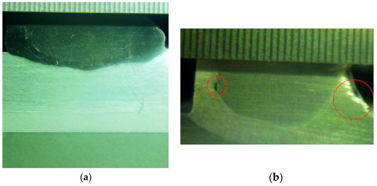
Figure 1.
Macroetched cross-sections of welded joints: (a) sample 3-3 (S235JR + N, etched with 3% nital); (b) sample 3-5 (X5CrNi18-10, electrochemically etched in 10% oxalic acid).
The macro-sections of specimens 6-3 and 6-5, which correspond to arc stud welding utilizing shielding gas (SG), are depicted in Figure 2. These cross-sectional analyses were conducted employing the same metallographic methodologies as those utilized for the preceding specimens, encompassing grinding, polishing, and etching—specifically, 3% nital for structural steel and 10% oxalic acid for stainless steel.
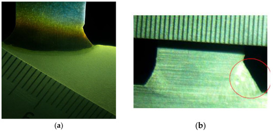
Figure 2.
Macrostructure of welded joints: (a) sample 6-3 (S235JR + N); (b) sample 6-5 (X5CrNi18-10). Imperfections are highlighted with red circles.
Sample 6-3, composed of structural steel (S235JR + N), displayed a slender yet uninterrupted fusion zone devoid of any discernible internal imperfections. The interface between the stud and the base metal was characterized by a smooth finish, with no indications of lack of fusion, porosity, or inclusions. Nevertheless, no critical defects were detected, and overall fusion quality was acceptable.
Conversely, the macro-section of sample 6-5 (X5CrNi18-10) exhibited a concentration of weld metal at the right margin of the fusion zone (highlighted in the image), likely attributed to the phenomenon of arc blow—a common occurrence in gas-shielded welding of austenitic steels. Notwithstanding this asymmetry, the joint demonstrated commendable penetration and an absence of observable defects such as cracks, porosity, or undercuts. The overall morphology suggests a robust weld that satisfies structural integrity standards, although enhanced arc control may be requisite for improved visual uniformity.
The macro-sections of specimens 9-3 and 9-5, which were welded employing the arc stud welding technique in conjunction with a radially symmetric magnetic field (SRM) and shielding gas, are depicted in Figure 3. Consistent with the preceding samples, the metallographic preparation involved meticulous sectioning, polishing to achieve a metallic sheen, and etching utilizing suitable reagents.
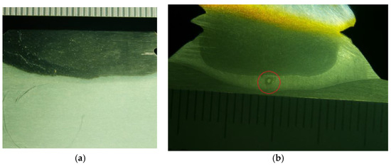
Figure 3.
Macroetched cross-sections of SRM-assisted welded studs: (a) sample 9-3 (S235JR + N, etched with 3% nital); (b) sample 9-5 (X5CrNi18-10, electrochemically etched in 10% oxalic acid), with a visible gas pore circled in red.
In the macro-section of specimen 9-3 (S235JR + N), a slender yet uninterrupted fusion zone is discerned, characterized by a marginally increased central melting, presumably affected by the stabilization of the arc and the effects of gas shielding. The geometry of the weld indicates effective fusion with regulated penetration and the absence of discernible defects, such as porosity, inclusions, or undercuts.
Conversely, the macro-section of specimen 9-5 (X5CrNi18-10) manifests a predominantly uniform and well-established fusion zone; however, a minor gas pore is observable at the center (marked in red), situated within the fused area. This defect is likely attributable to the entrapment of shielding gas during the rapid solidification process, a well-documented hazard associated with the welding of stainless steels under inert gas environments. Notwithstanding this localized imperfection, the overall morphology of the joint remains within acceptable quality thresholds, exhibiting commendable metallurgical bonding and the absence of significant discontinuities.
Across all analyzed samples, deformations in the shape of the welded circular flanges were minimal, and internal defects observed in the macro-sections were either absent or within acceptable limits. The fusion zones were continuous, with no critical flaws such as cracks, incomplete fusion, or significant porosity. Based on both visual and macrostructural evaluations, it can be concluded that the welds in all samples meet the required quality standards, confirming the effectiveness of the selected arc stud welding parameters and processes.
All the macro-sections confirmed continuous fusion zones, minimal deformation of the welded collars, and only minor imperfections, all within acceptable tolerances. According to ISO 5817:2014, all welds meet Quality Level C (Intermediate), with maximum undercut depths below 0.5 mm, no detected cracks or lack of fusion, and only minor acceptable surface irregularities. This level is appropriate for general structural applications where robust, reliable joints are required. Such welds are widely used for general structural steelwork, bridges, buildings, machinery, ship structures, and similar applications where good but not flawless welds are acceptable.
The penetration depth (d) of the welded joints was measured from the prepared macro-sections using ImageJ 1.54f software, a validated tool for digital image-based dimensional analysis. Penetration depth was defined as the maximum depth from the stud tip into the base material, as observed in the etched cross-sections. The measured values are listed in Table 6.

Table 6.
Measured weld penetration geometry of the samples.
The results show that the ARC CF (ceramic ferrule) method consistently produced the greatest average weld penetration depth. For stainless steel, the maximum penetration reached 3.547 mm, while for structural steel, it was 2.679 mm, confirming the effective heat confinement provided by the ferrule.
The ARC SG (shielding gas) method achieved moderate penetration depths with smoother bead contours but lower fusion than ARC CF, due to less arc confinement.
The ARC SRM (radially symmetric magnetic field) process produced the most uniform and symmetrical fusion zones but showed the shallowest penetration depths. The stabilizing effect of the magnetic field concentrates the arc at the stud tip and limits excessive heat spread into the base material, resulting in a narrower heat-affected zone (HAZ), which is beneficial for thin plates or heat-sensitive applications. The magnetic field assists in stabilizing arc motion, concentrating heat at the stud tip [26].
Figure 4 presents a boxplot that summarizes the measured penetration depths for each method and material. This visualization highlights the central tendency and variability for each technique. The plot confirms that ARC CF provides the deepest penetration, ARC SG delivers moderate and consistent results, and ARC SRM shows the lowest but most uniform penetration, which aligns with the macrostructural observations and measured values.
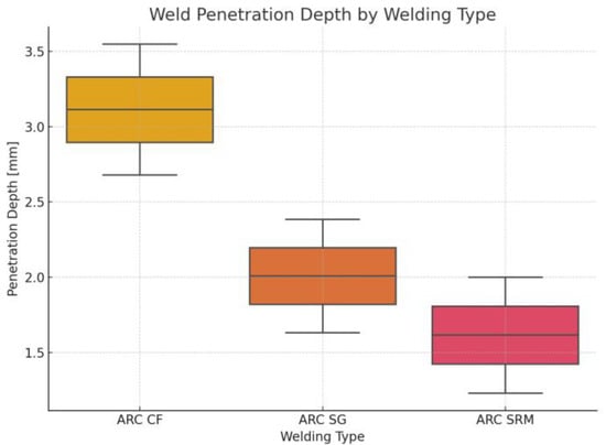
Figure 4.
Boxplot of measured weld penetration depths for ARC CF, ARC SG, and ARC SRM processes. Each value represents one welded sample per steel type.
Heat input and cooling rate control are key to avoiding undesirable phase transformations in the weld metal [27]. These findings indicate that stud welding with a ceramic ferrule yields the greatest weld penetration, enhancing joint strength through deeper fusion with the base material. Conversely, the SRM-assisted process provides the most controlled and narrow fusion zone, making it advantageous for applications requiring minimal thermal impact and high repeatability. This distinction is critical when selecting the most suitable welding method based on required joint integrity, material thickness, and production constraints.
3.2. Visual Appearance and Surface Quality
Visual inspections were performed on all welded studs to evaluate surface finish, stud alignment, and the presence of visible defects such as spatter, discoloration, or irregular weld collars. Representative photographs of the welded stud collars for each process are presented in Figure 5, Figure 6 and Figure 7.
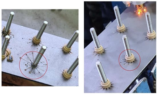
Figure 5.
Representative photographs of welded stud collars for ARC CF (ceramic ferrule) (left); example of a “hot weld” in ARC CF welding, showing over-spread molten metal beyond the ferrule boundary (right).
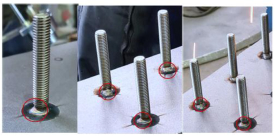
Figure 6.
Example of a “cold weld” in ARC SG welding, displaying irregular collar thickness around the stud.
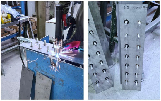
Figure 7.
Stud welding in progress using the PH-3N SRM gun with shielding gas supply (left); completed test plates with welded studs arranged according to the predefined template for macrostructural and mechanical testing (right).
The ARC CF (ceramic ferrule) process generally produced weld collars with slight surface roughness and occasional residue where the ferrule was removed after solidification. Minor ferrule breakage sometimes left small chips or marks on the surrounding area, requiring light post-weld cleaning to achieve a uniform appearance. A few samples displayed hot welds, where excessive heat input caused over-spreading of the molten metal beyond the ferrule boundary, often accompanied by spatter deposition (Figure 5). This phenomenon is typically associated with excessive welding current or extended arc duration; however, as the parameters were pre-validated by bend testing at a 60° angle, these anomalies were purely visual and did not compromise joint integrity. All ARC CF joints met the acceptance criteria defined in EN ISO 14555.
Heat input and shielding gas composition must be carefully controlled to maintain stable arc behavior and uniform weld bead formation [28]. Shielding gas composition significantly affects arc stability and weld collar uniformity [29]. Numerical analyses confirm that residual stress patterns and thermal gradients are highly dependent on the welding heat input and process duration [30].
The ARC SG (shielding gas) method resulted in cleaner weld collars with minimal surface contamination and very low spatter levels. The absence of ceramic ferrules eliminated ferrule residue, simplifying post-weld finishing. However, some samples exhibited cold welds characterized by an irregular or thin weld collar due to insufficient fusion or arc blow effects, as shown in Figure 6. Although the weld bead appeared continuous, variations in thickness around the stud were evident and could affect local fusion quality if not properly controlled. Careful adjustment of heat input and precise positioning of the welding gun are essential to prevent this defect. Irregular collar formation in SG welding can be attributed to unstable arc behavior, which is sensitive to heat input [31].
The ARC SRM (radially symmetric magnetic field) process produced the most uniform and symmetrical weld collars among the three methods. The enhanced arc stability provided by the magnetic field minimized arc wandering, resulting in smooth, well-centered collars with virtually no spatter or discoloration (Figure 7). This clean appearance and consistent collar shape make the SRM process particularly attractive for automated production lines where minimal post-processing is preferred.
Overall, all three welding processes produced visually acceptable welds with no surface flaws severe enough to compromise structural performance. However, differences in surface cleanliness, collar uniformity, and post-weld finishing requirements should be considered when selecting a suitable process, especially for applications where final appearance is critical.
3.3. Hardness Distribution
The hardness distribution across the weld metal and the heat-affected zone (HAZ) was measured using the Vickers HV10 method to evaluate the effect of each welding process on the local mechanical properties. Figure 8 presents the Vickers hardness (HV10) results for macro-sections 3-3, 6-3, and 9-3, which represent ARC CF (ceramic ferrule), ARC SG (shielding gas), and ARC SRM (radially symmetric magnetic field) welding processes, respectively. The corresponding average hardness values are summarized in Table 7.
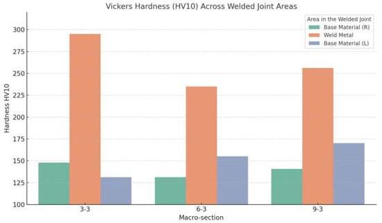
Figure 8.
Vickers hardness (HV10) distribution across the weld metal and adjacent base material for macro-sections 3-3 (ARC CF), 6-3 (ARC SG), and 9-3 (ARC SRM) on S235JR + N structural steel.

Table 7.
Average HV10 hardness values for samples 3-3, 6-3, and 9-3.
The results show a clear increase in hardness within the weld metal compared to the adjacent base material for all processes. The highest weld metal hardness was observed in sample 3-3 (ARC CF) at 295.0 HV10, which reflects the higher heat input and rapid solidification associated with deeper penetration and a larger molten zone, as discussed in Section 3.1.
Sample 6-3 (ARC SG) exhibited the lowest weld metal hardness (235.0 HV10) and slightly greater variation between the left and right base material measurements. This may indicate localized thermal gradients and less stable arc behavior compared to the other techniques.
The ARC SRM process (sample 9-3) demonstrated a balanced result, with weld metal hardness reaching 256.0 HV10 and a more consistent base material hardness on both sides of the joint. This suggests that the stabilizing effect of the radially symmetric magnetic field produces a focused, stable arc, controlling thermal diffusion and yielding a narrow HAZ.
Overall, the hardness measurements confirm that all three processes generated sufficient heat input to produce localized hardening of the weld metal, with ARC CF producing the highest peak hardness, while ARC SG and ARC SRM provided smoother hardness transitions and more uniform thermal effects. This behavior supports the suitability of SRM and SG techniques for applications where dimensional stability and controlled thermal impact are essential.
3.4. Observed Defects and Non-Destructive Testing Results
To verify the integrity of the welded joints, both non-destructive and destructive testing methods were applied in accordance with EN ISO 14555 and ISO 5817 standards. Non-destructive inspections included visual examination, liquid penetrant testing (PT), and radiographic testing (RT) where applicable.
Visual inspection served as the initial quality check to identify surface-level discontinuities such as cracks, undercuts, incomplete fusion, or excessive spatter. As discussed in Section 3.2, no critical surface flaws were found that would compromise structural performance. Minor variations, such as “hot welds” in some ARC CF samples and “cold welds” in certain ARC SG welds, were observed but did not affect the mechanical integrity of the joints.
Liquid penetrant testing was performed on representative samples to detect any surface-breaking cracks or porosity not visible to the naked eye. All tested welds passed the PT inspections without indications of unacceptable surface defects, confirming the effectiveness of the parameter control.
Radiographic testing was carried out on selected samples to identify internal discontinuities such as slag inclusions, porosity clusters, or incomplete fusion within the weld metal. The radiographs confirmed that all welds met the acceptance levels defined in ISO 5817 for Quality Level C, which is suitable for general structural applications. Minor isolated pores were occasionally detected in ARC CF welds, likely due to ferrule residue or gas entrapment, but remained within acceptable limits.
In addition to non-destructive testing, bend tests at angles of 30° and 60° were conducted to evaluate the ductility and bond strength of the welded studs. All samples withstood the required bending without failure at the weld collar, verifying sound metallurgical fusion.
Quality assurance in arc welding requires systematic control of imperfection levels, especially in production environments [32].
Overall, the combined results from visual inspection, penetrant testing, radiographic testing, and mechanical bend testing demonstrate that the applied welding parameters and techniques produced reliable and defect-tolerant stud welds compliant with relevant standards.
3.5. Comparative Performance Analysis
A comprehensive comparison of the three stud welding methods—ARC CF (ceramic ferrule), ARC SG (shielding gas), and ARC SRM (radially symmetric magnetic field)—highlights distinct performance trade-offs relevant to both structural and stainless-steel applications.
From the macrostructural results presented in Section 3.1, the ARC CF method consistently achieved the deepest weld penetration and the widest fusion zone. This greater heat input ensures robust metallurgical bonding and higher mechanical strength but requires careful control of ferrule integrity and post-weld cleanup due to possible residue or ferrule breakage.
The ARC SG technique demonstrated moderate penetration depths with good fusion continuity and minimal surface contamination. The absence of ferrules simplifies the welding process and reduces waste, making SG more convenient for applications where moderate joint strength and cleaner post-weld surfaces are acceptable. However, the observed “cold welds” in some samples underscore the need for precise alignment and parameter calibration to prevent incomplete fusion.
The ARC SRM method produced the most uniform fusion zones with the narrowest heat-affected areas. The magnetic field effectively stabilized the arc, resulting in highly repeatable weld collars with minimal spatter and excellent surface quality. Although the penetration depth was shallower than CF and SG, the controlled heat input minimizes distortion and residual stresses, which is advantageous for thin plates or parts with strict dimensional tolerances.
Hardness measurements confirmed that deeper penetration correlates with higher weld metal hardness for ARC CF, while ARC SG and SRM provided smoother hardness transitions and narrower thermal gradients, reducing the risk of brittle microstructures.
Defect analyses through visual, macrostructural, and non-destructive testing verified that all joints met the acceptance criteria for Quality Level C under ISO 5817:2014. Minor defects, such as isolated gas pores in SRM or arc blow in SG, were within allowable limits and did not compromise overall weld performance.
Overall, the selection of an optimal stud welding process depends on specific application requirements. ARC CF is suitable when maximum joint strength and deep fusion are priorities. ARC SG balances reasonable strength with cleaner surfaces and simpler processing. ARC SRM is recommended when high repeatability, minimal heat input, and excellent surface finish are critical, particularly for automated production and thin-walled assemblies.
4. Discussion
This research comprehensively investigated the performance of three arc stud welding techniques—ARC CF (ceramic ferrule), ARC SG (shielding gas), and ARC SRM (radially symmetric magnetic field)—applied to structural steel (1.0038) and stainless steel (1.4301). An integrated approach combining macrostructural examination, hardness testing, visual inspection, and non-destructive evaluation was used to characterize weld quality, penetration geometry, and defect formation. Weld pool behavior directly reflects the combined effects of process parameters and material thermal conductivity [33].
The main conclusions are as follows:
- 1.
- Penetration depth and fusion quality:The ARC CF method achieved the greatest penetration depths (2.679–3.547 mm) due to effective arc confinement by the ceramic ferrule. ARC SG produced moderate penetration (1.632–2.383 mm) with stable fusion, while ARC SRM yielded the shallowest but most uniform fusion zones (1.232–2.001 mm), minimizing thermal impact.
- 2.
- Surface quality and visual defects:Visual inspection confirmed process-dependent surface features: “hot welds” in ARC CF due to high heat input, and “cold welds” in ARC SG linked to arc blow or gun misalignment. ARC SRM produced the cleanest weld collars with minimal spatter, ideal for applications requiring high surface quality and low post-processing effort.
- 3.
- Hardness distribution:Vickers HV10 testing verified that higher penetration correlated with increased weld metal hardness: ARC CF reached up to 295 HV10, ARC SRM up to 256 HV10, and ARC SG up to 235 HV10. These results confirm controlled energy input without undesirable hardness gradients or brittle phases [34].
- 4.
- Defects and compliance:Non-destructive liquid penetrant testing, performed in accordance with EN ISO 3452-1:2021, confirmed the absence of surface-breaking defects. Visual and radiographic inspections verified that all welds complied with ISO 5817:2014 Quality Level C, with only minor, acceptable imperfections.
- 5.
- Process selection recommendations:
- ○
- ARC CF is best suited when maximum joint strength and deep fusion are priorities, but demands careful ferrule handling and spatter control.
- ○
- ARC SG balances adequate penetration and cleaner post-weld surfaces, but requires precise alignment to avoid cold welds.
- ○
- ARC SRM offers the highest process stability and best surface finish with low heat input, making it highly suitable for thin sections or applications sensitive to heat distortion.
Future research should expand on these findings as follows:
- Assessing the fatigue life and cyclic loading behavior of welded studs, especially for ARC SRM specimens [25,35];
- Refining SRM parameters (current control, shielding gas composition) to increase fusion depth while minimizing porosity formation [36,37];
- Investigating alternative material combinations and larger stud diameters to validate scalability;
- Applying advanced numerical methods such as finite element modeling to simulate thermal cycles, residual stresses, and phase transformations more accurately [36,37].
These directions will deepen understanding of arc stud welding process mechanics and guide further optimization for diverse industrial applications.
Short cycle arc stud welding also benefits from process optimization strategies similar to those discussed here [25].
Further parameter optimization could improve fusion depth and reduce defect formation, especially in high-strength steels [38].
5. Conclusions
This study provides a comprehensive experimental comparison of three arc stud welding techniques—arc welding with a ceramic ferrule (ARC CF), arc welding with shielding gas (ARC SG), and arc welding assisted by a radially symmetric magnetic field (ARC SRM)—applied to structural steel (1.0038) and stainless steel (1.4301). Macrostructural examination, Vickers hardness testing, visual inspection, non-destructive testing, and mechanical bend tests were conducted to assess the quality and integrity of the welded joints under realistic conditions.
The results demonstrate that the ARC CF process consistently produced the deepest weld penetration, reaching up to 3.547 mm in stainless-steel joints, which is advantageous for applications requiring high load-bearing capacity and robust joint strength. However, this method also tended to generate more molten metal spatter and irregular bead shapes, which may necessitate additional post-processing to achieve the desired surface finish. In contrast, the ARC SG technique achieved moderate penetration depths with stable fusion quality but was more susceptible to cold welds if the welding gun was not precisely aligned, highlighting the importance of careful parameter control.
Among the three methods, the ARC SRM process resulted in the lowest penetration depths but produced the most uniform and symmetrical weld collars with minimal spatter and excellent visual appearance. This stable arc behavior and reduced heat input make the SRM technique particularly well suited for applications where minimal thermal distortion and high surface quality are required, such as in visible architectural joints or thin sheet assemblies.
The hardness measurements confirmed that all three processes effectively increased the hardness of the weld metal relative to the base material, with ARC CF reaching the highest recorded value of 295 HV10, followed by ARC SRM and ARC SG. No evidence of undesirable brittle phases or unacceptable hardness gradients was found, indicating that the thermal cycles associated with stud welding were well controlled within acceptable limits.
Non-destructive liquid penetrant testing, performed according to EN ISO 3452-1:2021, verified the absence of surface-breaking defects in all welded specimens. Combined with visual inspection and mechanical bend tests, these results confirm that all joints met the requirements of ISO 5817:2014 Quality Level C, demonstrating their suitability for general structural applications.
From a practical perspective, the findings underline the need to manage molten metal spatter in ARC CF to ensure operator safety and minimize post-weld cleaning, and to mitigate arc blow effects in ARC SG to maintain consistent weld quality. The excellent arc stability and visual appearance achieved with ARC SRM suggest significant potential for its use in precision applications where minimal heat input and clean weld surfaces are critical.
Overall, this comparative study offers valuable guidance for engineers and practitioners in selecting and optimizing stud welding techniques to balance mechanical performance, visual quality, and project-specific constraints. Future research should expand on these results by exploring high-strength and ultra-high-strength steels, refining SRM process parameters, and examining the long-term fatigue performance of stud welded joints under cyclic loading to further ensure structural safety and durability.
Future research should extend to the following areas:
- Stud welding of cold-formed high-strength and ultra-high-strength steels [5];
- Development of improved arc control devices and advanced process variants [5];
- Investigations into fatigue crack propagation under cyclic loads to ensure long-term joint performance and structural safety [39].
Author Contributions
Conceptualization, T.T. and T.M.; methodology, T.T.; software, T.T.; validation, T.M.; formal analysis, T.T.; investigation, J.G. and L.V.; resources, J.G.; data curation, L.V.; writing—original draft preparation, T.T.; writing—review and editing, T.T. and L.V.; visualization, L.V.; supervision, T.M.; project administration, T.T.; funding acquisition, T.M. All authors have read and agreed to the published version of the manuscript.
Funding
This research was funded by the project “Analysis of Surface Parameters of Metal Coatings Applied to Polymer Structures Manufactured by Additive Technology Using Computer Vision (APPMPPTRV)”, grant number NPOO2024-2, Zagreb University of Applied Sciences. The APC was funded by the Zagreb University of Applied Sciences.
Institutional Review Board Statement
Not applicable.
Informed Consent Statement
Not applicable.
Data Availability Statement
The original contributions presented in this study are included in the article. Further inquiries can be directed to the corresponding author.
Conflicts of Interest
The authors declare no conflict of interest.
Abbreviations
The following abbreviations are used in this manuscript:
| ARC CF | Arc stud welding with ceramic ferrule |
| ARC SG | Arc stud welding with shielding gas |
| ARC SRM | Arc stud welding with a radially symmetric magnetic field |
| RF | Ring ferrule |
| SRM | Stud welding with a radially symmetric magnetic field |
| HV | Vickers hardness |
| DASW | Drawn arc stud welding |
| DOE | Design of experiment |
| EN ISO | European Standard for Arc Stud Welding of Metallic Materials |
| PT | Penetrant testing |
| NDT | Non-destructive testing |
| HAZ | Heat-affected zone |
| MTC | Mill test certificate |
References
- Nishikawa, W. The Principle and Application Field of Stud Welding. Weld. Int. 2003, 17, 699–705. [Google Scholar] [CrossRef]
- Gao, X.; Liu, Y.; Wu, Y.; Zhao, H. A review on arc stud welding technology and its developments. J. Manuf. Process. 2022, 79, 437–449. [Google Scholar] [CrossRef]
- Chi, Q.; Zhang, J.; Fu, J. Development and Application of Arc Stud Welding Technology. Weld. Technol. 2003, 32, 18–20. [Google Scholar] [CrossRef]
- Fu, J.; Zhang, Y.; Ma, D. Stud Welding Technology in Building Engineering (1)—Present Status and Outlook of Stud Welding Technology in Steel Structure Engineering. Steel Constr. 2002, 17, 56–60. [Google Scholar] [CrossRef]
- Köhler, M.; Wieschemann, A.; Dilthey, U. Welding of High-Strength Steels Using Arc Stud Welding Techniques with Process Monitoring. Weld. World 2006, 50, 19–27. [Google Scholar] [CrossRef]
- Szymanski, R.; Gazda, T.; Kozioł, M. Effect of Power Supply and Arc Control on Arc Stud Welding Quality. Weld. Int. 2018, 32, 257–266. [Google Scholar]
- Tanaka, K. Recent Advances in Capacitor Discharge Stud Welding. Weld. World 2018, 62, 357–364. [Google Scholar]
- Hameed, F.H.; Mohamed, M.T.; Sami, A.; Nawi; Gattmah, J. Dissimilar Arc Stud Welding AISI 304/AISI 1008: Mechanical Properties. IOP Conf. Ser. Mater. Sci. Eng. 2021, 1076, 012079. [Google Scholar] [CrossRef]
- Hartz-Behrend, K.; Marqués, J.L.; Forster, G.; Jenicek, A.; Müller, M.; Cramer, H.; Jilg, A.; Soyer, H.; Schein, J. Stud Arc Welding in a Magnetic Field-Investigation of the Influences on the Arc Motion. J. Phys. Conf. Ser. 2014, 550, 012003. [Google Scholar] [CrossRef]
- Jones, J.E.; Rhoades, V.L.; Holverson, T.E.; Cuneo, A.N.; Madden, S.K. Stud Welding System, Consumables, and. Method. Patent PCT/US2012/046743 (WO2013012746A2), 13 July 2012. Available online: https://patentscope.wipo.int/search/en/WO2013012746 (accessed on 23 June 2025). [CrossRef]
- Abass, M.H.; Alali, M.S.; Abbas, W.; Shehab, A.A. Study of solidification behaviour and mechanical properties of arc stud welded AISI 316L stainless steel. J. Achiev. Mater. Manuf. Eng. 2019, 97, 5–14. [Google Scholar] [CrossRef]
- Hsu, C.; Mumaw, J. Weldability of Advanced High-Strength Steel Drawn Arc Stud Welding. Weld. J. 2011, 90, 36–47. [Google Scholar]
- Eyercìoğlu, Ö.; Ucar, T. The effect of arc stud welding parameters on mechanical properties of docol 1500m advanced high strength steel welding joints. Int. J. Res. 2024, 12, 82–98. [Google Scholar]
- Afkhami, S.; Björk, T.; Larkiola, J. Weldability of Cold-Formed High Strength and Ultra-High Strength Steels. J. Constr. Steel Res. 2019, 158, 86–98. [Google Scholar] [CrossRef]
- HRN EN ISO 14555; Welding—Arc Stud Welding of Metallic Materials, 4th ed. Croatian Standards Institute: Zagreb, Croatia, 2017.
- HRN ISO 3452-1; Non-Destructive Testing—Penetrant Testing—Part 1: General Principles. Croatian Standards Institute: Zagreb, Croatia, 2021.
- ISO 5817; Welding—Fusion-Welded Joints in Steel, Nickel, Titanium and Their Alloys—Quality Levels for Imperfections. International Organization for Standardization: Geneva, Switzerland, 2014.
- ISO 13918; Welding—Studs and Ceramic Ferrules for Arc Stud Welding. International Organization for Standardization: Geneva, Switzerland, 2017.
- DIN EN 10204/3.1; Inspection Certificate. Bolte: Neumark, Germany, 2021.
- Haridas, A.D.B.M.; Asari, R. Drawn Arc Stud Welding—Process Parameters Analysis & Simulation Development. 2020. Available online: https://www.researchgate.net/publication/349238319_Drawn_Arc_Stud_Welding_-Process_Parameters_Analysis_Simulation_Development?channel=doi&linkId=6026354592851c4ed566a055&showFulltext=true (accessed on 23 June 2025). [CrossRef]
- Ghany, A.; Newby, M. Optimization of process parameters for improved stud welding of stainless steel. J. Mater. Process. Technol. 2014, 214, 2428–2435. [Google Scholar]
- Wu, Z.; Guo, X.; Wang, Z. Effect of stud diameter and welding current on the strength of arc stud welds. J. Mater. Process. Technol. 2019, 264, 159–167. [Google Scholar]
- Kumar, S.; Singh, K. Review on quality assurance techniques in arc welding. J. Manuf. Process. 2020, 55, 259–276. [Google Scholar]
- Wang, L.; Zhang, Y.; Sun, Y. Optimization of Drawn Arc Stud Welding for High Strength Steels. Mater. Des. 2021, 198, 109358. [Google Scholar]
- Kankuri, E.; Heljo, J.; Palonen, J.; Kiviranta, L.; Miettunen, K.; Mäki-Jaskari, M. Microstructure and Mechanical Properties of Arc Stud Welded Joint of High-Strength Structural Steel S700MC. Mater. Des. 2021, 200, 109427. [Google Scholar]
- Li, Y.; Liu, Y.; Zhang, Y. Dynamic analysis of arc motion in magnetic field assisted stud welding. Weld. J. 2019, 98, 399s–408s. [Google Scholar]
- Ma, J.; Zhang, Y.; Liu, X. Experimental study on arc blow in arc stud welding. Int. J. Adv. Manuf. Technol. 2018, 95, 2401–240831. [Google Scholar]
- Zhang, J.; Feng, J.; Yang, Z. Heat input and arc stability in gas shielded arc stud welding. Weld. J. 2015, 94, 147s–153s. [Google Scholar]
- Park, J.; Lee, Y.; Kim, S. Influence of Shielding Gas Composition on Stud Weld Quality. J. Mater. Process. Technol. 2019, 271, 136–143. [Google Scholar]
- Chen, L.; Wang, Y.; Li, X. Numerical analysis of temperature field and residual stress in arc stud welding. Int. J. Heat Mass Transf. 2016, 99, 846–854. [Google Scholar]
- Song, J.; Yin, Z.; Xiong, J. Process optimization of short cycle arc stud welding. J. Mater. Process. Technol. 2017, 249, 304–311. [Google Scholar]
- Zhang, Y.; Xu, G.; Liu, J.; Chen, X. Numerical simulation and experimental study of stud welding process for dissimilar metals. J. Mater. Process. Technol. 2017, 245, 107–116. [Google Scholar]
- Gong, S.; Sun, Z.; Chen, W. Effects of welding parameters on weld pool behavior in stud arc welding. Int. J. Adv. Manuf. Technol. 2015, 79, 1579–1587. [Google Scholar]
- Ramasamy, P.; Senthil Kumar, P.; Padmanabhan, K.A. Experimental analysis and microstructure characterization of drawn arc stud welding on high-strength steel. Mater. Des. 2015, 65, 978–987. [Google Scholar]
- Lee, J.; Kim, H. Fatigue Performance of Stud Welded Connections in Composite Structures. Eng. Struct. 2016, 127, 521–530. [Google Scholar]
- Cho, H.; Lee, H.; Bae, J. Numerical and experimental investigation on residual stress in arc stud welded joints. J. Constr. Steel Res. 2017, 136, 78–86. [Google Scholar]
- Liu, X.; Wang, Y.; Ma, J. Residual Stress and Distortion in Stud Welding: Finite Element Analysis and Experimental Verification. Int. J. Adv. Manuf. Technol. 2022, 119, 4299–4311. [Google Scholar]
- Zhang, Y.; Wu, S.; Li, Y. Numerical Simulation of Arc Behavior in Stud Welding Assisted by Magnetic Field. Weld. J. 2017, 96, 93s–101s. [Google Scholar]
- Chen, Q.; Han, J.; Li, Z. Evaluation of fatigue crack propagation in stud welded joints. Int. J. Fatigue 2019, 127, 208–215. [Google Scholar]
Disclaimer/Publisher’s Note: The statements, opinions and data contained in all publications are solely those of the individual author(s) and contributor(s) and not of MDPI and/or the editor(s). MDPI and/or the editor(s) disclaim responsibility for any injury to people or property resulting from any ideas, methods, instructions or products referred to in the content. |
© 2025 by the authors. Licensee MDPI, Basel, Switzerland. This article is an open access article distributed under the terms and conditions of the Creative Commons Attribution (CC BY) license (https://creativecommons.org/licenses/by/4.0/).