Abstract
A product development process establishes requirements not just for the new product’s quality and performance, but also for its manufacturing process, to guarantee that the item is manufactured with minimal impact. This is because, if an issue is discovered after the product has been released, the implications go beyond the expensive cost of the repair; the physical ergonomics problem can affect the worker’s comfort, productivity, and product quality. Virtual reality and digital human modeling are often employed in Industry 4.0 to evaluate ergonomics, but they are rarely used to examine physical ergonomics throughout the product development phases. Our study presents design guidelines to combine virtual reality and digital human modeling to anticipate the physical ergonomics evaluations of the assembly process while the product is still in development. Based on physical observations of body-posture angles and total effort classification, our proof of concept performed comparably to conventional methods. We also observed comparable results when we analyzed attributive factors such as hand clearance and strength. In contrast, our proof of concept has been shown to be limited for occupations involving extra ergonomic physical risk factors, such as touch perception, temperature fluctuations, or size changes.
1. Introduction
Conceptualization, design, fabrication, implementation, and post-launch evaluation are integral components of the product development process [1]. The effectiveness and efficiency of newly introduced products are directly influenced by the management of the development process, which necessitates the establishment of product and process design standards, among other factors, to ensure manufacturability with minimal environmental impact.
Detecting issues early in the product development stage (simulation) is important [2]. When problems are identified around or after the product launch, the cost of rectification escalates dramatically. This can be attributed to the fact that, at this stage of development, production resources are nearly exhausted, and modifications become increasingly complex and costly. In contrast, all prior phases, from definition to optimization, are conducted within a virtual environment that is simple, efficient, and inexpensive to modify [2].
From an ergonomic standpoint, the early identification of issues during virtual manufacturing not only saves time and resources but also minimizes workers’ exposure to unnecessary injury risks, thereby enhancing workplace well-being [3].
In the context of Industry 4.0, advancements in technology and the automation of production processes have created a conducive environment for the implementation of various technologies that support multiple stages of this production process, ranging from activity monitoring to workplace enhancements [4]. Among these technologies are virtual simulations such as virtual reality (VR) and digital human modeling (DHM), both of which operate within a three-dimensional (3D) environment. Virtual reality is “a computer-generated digital environment that can be experienced and interacted with as if it were real” [5]. In contrast, DHM simulations are non-immersive, utilizing computer-generated mannequins to replicate human movements [6,7].
Virtual simulation, in the context of VR and DHM technologies, employs computer modeling and simulation techniques that have been extensively utilized for over half a century across various sectors, including education, healthcare, entertainment, culture, sports, engineering, military forces, and more. However, these technologies have only recently emerged as valuable tools in the industrial sector [8].
Although scaling human models is one of the fundamental functions of digital human modeling (DHM), accurately representing the diversity of the human population remains challenging due to the significant variation in body sizes and shapes [9].
Despite their wide-ranging applications, these technologies have not yet been extensively explored by industries for physical ergonomics studies throughout the product development stages. Recent research highlights the growing interest in employing immersive technologies for ergonomics assessment in industrial settings. A systematic review, for example, mapped 250 patents and 18 scientific articles and revealed an exponential increase in innovations combining virtual reality and DHM for ergonomic applications in product development [10]. Their findings emphasize the strong potential of integrating the two technologies to detect ergonomic risks early in the design process, which could significantly reduce costs and enhance worker well-being. However, the authors note that despite broad consensus on these benefits, most existing studies and applications continue to address pre-designed manufacturing environments, where resources are already deployed, rather than focusing on proactive ergonomics during early development phases. Moreover, the integration of VR and DHM in a single analysis remains rare, suggesting a disconnect between academic advances and industrial adoption. This gap indicates the need for further applied research and experimental validation of integrated VR-DHM frameworks within the early stages of industrial product design.
Thus, this study presents design guidelines to combine virtual reality and digital human modeling to anticipate the physical ergonomics evaluations of the assembly process while the product is still in development.
This approach contributes to the field by demonstrating how the integration of digital human modeling and virtual reality can be applied proactively still during the product development phase, before workstations and tasks are physically implemented. Rather than focusing on the analysis of existing production environments, our approach enables ergonomic evaluations to be conducted based on CAD models, process plans, and digital prototypes. This perspective supports early identification of ergonomic risks, facilitates iterative design improvements, and reduces the cost and complexity of late-stage modifications. Foreseeing workplace ergonomics issues using virtual simulation tools strengthens the design of safer, more efficient, and human-centered manufacturing systems.
2. Materials and Methods
Given the recent emergence of research on virtual reality technology, this paper takes an exploratory stance and prioritizes qualitative inquiry [11]. Five senior practitioners and researchers with expertise in virtual reality, automotive product development, and ergonomics assessments defined the initial research strategy, which was then assessed by three other senior researchers, and finally all authors peer debriefed the strategy.
We followed the design science research (DSR) paradigm, which not only contributes to the advancement of knowledge but also addresses real-world applications related to the research problem or opportunity [12]. According to the DSR artifact taxonomy, our study provides an artifact of type guideline; the use type is support, and the structure is the suggestion regarding behavior in a particular situation. A guideline provides a generalized suggestion about system development; it does not have a fixed structure, but will usually make statements like “in situation X one could/should do Y”.
We carried out the following DSR’s six steps: (1) identify the problem; (2) define the solution objectives; (3) design and development; (4) demonstration; (5) evaluation; and (6) communication.
In DSR steps 1 and 2, the problem was identified, and the objectives of the research were set by conducting a systematic review of the literature and patents on this topic [10]. This review followed the Preferred Reporting Items for Systematic Reviews and Meta-Analyses (PRISMA) principles [13] and a method comprising planning, scoping, searching, assessing, and synthesizing [14].
Step 3 involved the design and development of the artifact. Based on the referred literature and patents’ review, we focused on the automotive industry because it has a large manufacturing operation and various ergonomic injury-causing elements. The following four assembly procedures were selected: the front transmission axle, the rear transmission axle, the radiator, and parking brake. These selected procedures were not chosen randomly or for convenience. Instead, the selection was based on ergonomic injury data from the automotive industry, specifically focusing on the body parts most frequently associated with injuries over the last five years. For the assessment of posture, hand clearance, and strength, body postures were selected, which affects the shoulder, lower back, hands (reach and clearance), wrist, elbow, and knee, which have been reported as the primary causes of ergonomic-related injuries in the industrial business in the last five years [15].
Then, we simulated the four assembly procedures in VR and DHM, focusing on the physical ergonomics conditions. To create a realistic simulation, everything in the workplace (parts, racks, tools, and equipment, as well as the worker him/herself) was exported from Computer-Aided Develop (CAD) Siemens NX, version 1899, and used to design the scenario for each assembly procedure. The VR simulations used a VIVE PRO head-mounted display (HMD) (HTC Corporation, New Taipei City, Taiwan) while the DHM simulations used a Dell notebook with an Intel CoreTM processor i3-1005G1. Both simulations were supported by Siemens Tecnomatix 16 and Jack 9.0 software; these tools were chosen since they are typical automotive industry resources.
Jack is developed by Siemens Digital Industries and enables the improvement of product ergonomics and the refinement of industrial processes through human modeling and simulation. It is also regarded as one of the premier human simulation tools for conducting ergonomic evaluations [16]. Jack’s simulation tools allow users to run a variety of analytic methods, including Rapid Upper Limb Assessment (RULA); Ovako Working Posture Analysis (OWAS); the National Institute for Occupational Safety and Health (NIOSH) lift equation; and hand clearance, strength, and zone of view [16]. With RAMSIS and Delmia, Jack is one of the most often used commercial software for DHM applications [17].
Tecnomatix is also a product from Siemens. This software is designed to empower industries to execute virtual simulations in manufacturing and the process. Tecnomatix can be used for various purposes, like programming and planning of production lines using robots, simulation of discrete events, simulation of flow in production lines, human modeling, simulation and analysis of ergonomics aspects, robot programming, and VR applications [18]. VR applications were adopted in this study since they are common resources in the automotive industry, provided by the same supplier as Jack. Among the main applications are test design and operational aspects of a wide variety of human factors, including injury risk, timing, user comfort, reachability, energy expenditure, fatigue limits, and other important parameters. This helps to ensure compliance with ergonomic standards during planning and to avoid the discovery of human performance and feasibility issues during production [18].
The Sue Rodgers checklist, a commonly used tool in the automotive sector, mainly those of North American origin, was utilized to conduct the ergonomic assessment. The Sue Rodgers is an assessment of muscle fatigue developed by the American doctor Suzanne Rodgers in 1992 [19]. The method aims to assess the fatigue that accumulates in the muscle. It is an ergonomic job-level assessment tool that generates a change priority score ranging from low to extremely high. Each body region is analyzed separately, such as the head and neck, shoulder and arm, knee and lower leg, and so on. The Sue Rodgers method considers three factors: effort, effort duration, and effort frequency. This approach yields a three-digit number, with each digit representing one of the three examined factors [19].
Figure 1 illustrates the hardware adopted, the immersive and non-immersive simulations, and the validation concept.
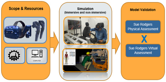
Figure 1.
Hardware, and the immersive and non-immersive simulations.
DSR’s step 4 involves demonstrating the artifact; thus, we demonstrated a proof of concept to four senior researchers of our research group, and they suggested minor improvements. For this, in the automotive industry, ergonomic analyses are already performed by feeding data into the Sue Rodgers form generated from observation and/or measurement of the worker executing his/her activities in the physical environment. Then, this measurement was carried out in an immersive environment, using a proof of concept. The feasibility was verified by comparing the outcomes of our analysis to those of actual (physical) analysis, both using Sue Rodgers’ checklist as a reference. The Sue Rodgers physical assessments were then compared to Sue Rodgers’ proof-of-concept assessments.
Step 5 of DSR consists of gathering evidence that the proposed artifact is useful, meaning that it works and does what it is intended to do [12]. To evaluate our preliminary guidelines in terms of validity criteria, we conducted an exploratory focus group with eight senior researchers of our group, experts in virtual reality and industrial applications, to examine our perceptions. Qualitative research analyzes textual information, allowing researchers to interpret themes or patterns that emerge from the data [20], so we analyzed the data to extract meaning from the text; this entailed segmenting, deconstructing, and reconstructing the data [20]. We then compiled our observations into design guidelines.
Step 6 of DSR consists in this publication to communicate our findings, which are described in the following sections.
3. Results and Discussion
Our findings are presented and discussed in the sections that follow.
3.1. Simulating the Physical Ergonomic Conditions of Assembly Procedures in VR and DHM
The next sections present the creation of CAD models/scenarios and the simulation of physical ergonomics analysis.
3.1.1. Creation of CAD Models and Scenarios
For the virtual analysis to accurately reproduce the physical one, scenarios containing all the details linked to the assembly procedures must be created before running the simulation. The key point here is to ensure that all assembly procedure parts, particularly the worker, are correctly positioned [4].
All workplace tools and facilities, the sequence of assembly procedures, and all tasks involved in such a study should be mapped, photographed, and recorded [21], and these data should be examined to determine which elements will be exported to the CAD model.
The simulation captured an image from physical assembly procedures that cover all relevant workplace information, such as the assembly sequence. Tools are essential in the execution of assembly procedures, such as those found in the automotive industry. Some tools used in this simulation include pliers, portable nutrunners, torque wrenches, spanners, and special tools (Figure 2).
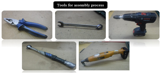
Figure 2.
Workplace tools.
The industrial facilities and resources are equally important for the execution of working tasks. Tool carts, shelves, roller racks, and skids are examples of those features shown in Figure 3.
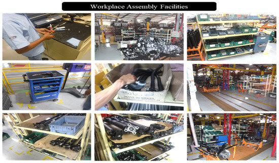
Figure 3.
Workplace resources and facilities.
Continuing the photographic mapping of the physical assembly procedures, the sequence conducted by the worker in each of the four procedures was described. Only the most important steps of each procedure are shown in the pictures. In addition, the process videos were used to conduct the simulation.
The first procedure assembly is the Front Driveshaft, in which the worker must pick up the fasteners and parts from the shelves, align the parts with the transfer case flange, and take a manual pre-torque (using hands), with a torque meter and device to rotate the set and apply torque in all screws; and, finally, the worker must mark the torqued nuts with sealing paint (Figure 4).
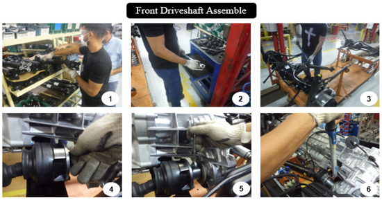
Figure 4.
Front Driveshaft assembles.
The Rear Driveshaft assembly procedure is quite similar to the Front Driveshaft assembly, with the key difference being that workers must move heavy parts from storage to the workplace. The Rear Driveshaft must be aligned in differential and connected, with the pre-torque applied with a spanner (Figure 5).
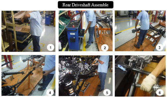
Figure 5.
Rear Driveshaft assembly.
The radiator hose-clamp procedure begins with picking up the hose bracket and tool. The upper half of the hose is fastened in the radiator, and the worker must squat to select the clamp at the radiator’s back (Figure 6).
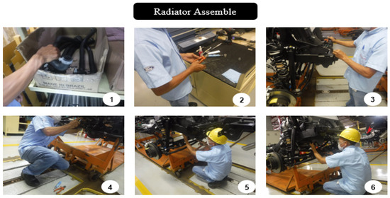
Figure 6.
Radiator-hose clamp.
The last procedure assembly is to adjust the parking brake; the worker uses portable screwdrivers and a support device to fix inside the vehicle, move the lever up and down ten times, and then align and add the required torque (Figure 7).
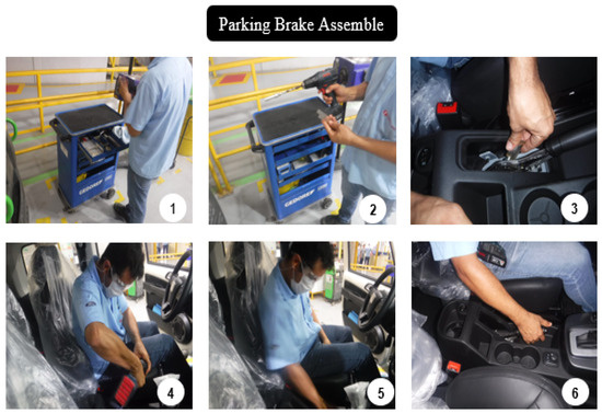
Figure 7.
Parking-brake adjustment.
After mapping and recording the actual workplaces, CATIA V5 was utilized to export three-dimensional (3D) models. As seen in the illustrations below, the first virtual illustration is about the tools needed to finish the assembly. Figure 8 shows the tools’ 3D CAD models.
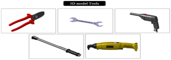
Figure 8.
CAD models tools.
Figure 9 shows the industrial facilities and resources that are available, as seen in the conventional method.
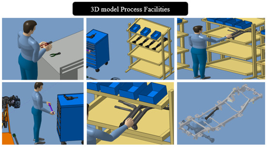
Figure 9.
CAD models facilities and resources.
Figure 10 illustrates the four assembly procedures simulated. The goal is to incorporate manikins and routines into the procedure’s execution.
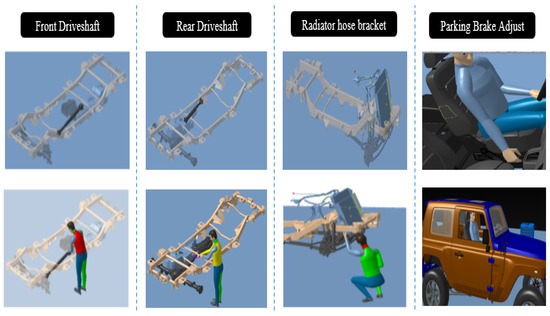
Figure 10.
CAD models assembly procedures.
Once all the elements in the CAD model were created and reproduced in reality, they were imported into Jack and Tecnomatix and built four scenarios, positioning everything that affects worker routine, and then the worker started the simulations. Figure 11 shows scenarios that contain the entire set of information needed to effectively simulate the physical assembly procedures.
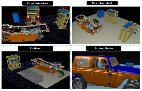
Figure 11.
Virtual scenarios in Jack.
With Jack, specific analysis tools were used to obtain quantifiable data on postures (joint angles), access (hand release), and force/torque (strength). Tecnomatix, focused on virtual reality application, was used for an immersive and qualitative evaluation, allowing users to identify issues of visibility, access, and spatial interaction from the worker’s perspective.
It is important to review the scenarios created with a senior manufacturing engineer and/or an experienced worker [22]. A careful assessment of the images and videos, as well as the participation of a manufacturing specialist who is more familiar with the assembly procedures, is required to ensure that the scenario’s composition is accurate.
3.1.2. Simulating Physical Ergonomics Analysis
After completing all the scenarios, various simulations were run to analyze the worker’s postures and other ergonomic conditions while executing the task in the workplace. These simulations included all the worker’s tasks, such as accessibility, reaching and manipulating things, gripping, and picking up tools and parts during the assembly procedure.
VR provided a good comprehension of tasks from the perspective of the worker, allowing for an immersive interaction. It was feasible, for example, to walk around the vehicle in production and imagine different ways to carry out duties, obtaining a clear understanding of the worker’s difficulty in performing the assembly procedures.
DHM simulations were performed with Jack to provide measurable data for postural analysis, an available resource that was used to complement VR analyses.
The digital human model in Jack is made up of various elements. The Jack human library contains a large number of default models. Depending on the percentile population, each default human figure has some default segment lengths (e.g., 95th, 50th, or 5th percentile) [9].
The automotive industry set the 50th percentile female as the default for most factories worldwide. The percentile was calculated using statistical assessments of its plants’ populations over the world (except for Asians). According to the assessment, the manikins’ dimensions (Figure 12) are sufficient to accommodate 90 percent of this industry’s workers [9]. To evaluate specific tasks, like hand clearance and strength, we used percentile 95th male.
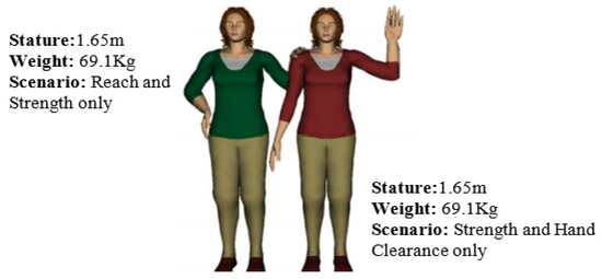
Figure 12.
Jack manikins [9].
The selection of the 50th percentile female and 95th percentile male models was based on an extensive internal anthropometric study conducted by a large automotive company over 10 years; the company concluded that these percentiles adequately represent approximately 90% of their operational workforce. However, we acknowledge that this approach does not fully capture the diversity of the workforce, especially regarding populations with distinct anthropometric profiles, indicating the need for complementary studies or more inclusive models. This limitation underscores the need for complementary studies or the development of more inclusive models, as discussed in Section 4.
The first virtual simulation was related to the installation of the Front Transmission Axle, where Jack began using the DHM for pre-torque analysis, one of the most ergonomically critical tasks of this assembly procedure. This simulation (Figure 13) shows that the worker is unable to access the screw head to perform pre-torque, a manual task, indicating that the assembly procedures do not meet a minimum hand clearance requirement.
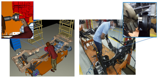
Figure 13.
Hand clearance simulation (non-immersive).
All simulations are shown alongside photographs from the physical assembly procedures, to make it easier to compare the methods.
Tecnomatix reproduced the identical assembly procedure in VR. Figure 14 illustrates that the interface condition between the driveshaft and gearbox does not allow for manual pre-torque because the back of the hand will touch the gearbox, limiting finger access to the screws.
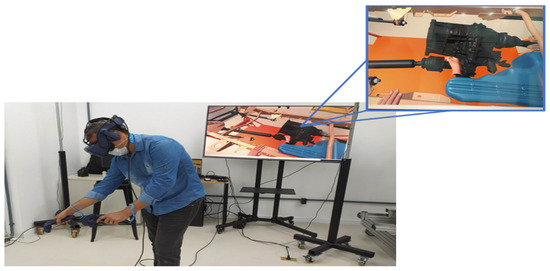
Figure 14.
Hand clearance simulation (immersive).
Every manual task must give sufficient hand access around all parts or tools required to accomplish the assembly procedure properly [9]. The clearance required for the 95th percentile male wearing production gloves of 1.5 mm in thickness is shown in Figure 15.
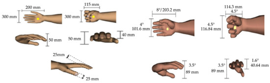
Figure 15.
Hand clearance requirements [22].
The DHM Rear Driveshaft assembly procedure was simulated. Figure 16 shows an analysis of wrist posture during a torque application task that indicates evidence of an extreme radial wrist deviation of 38.7 degrees on a scale ranging from −45 to 45 degrees.
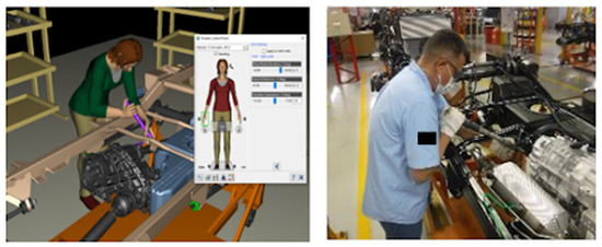
Figure 16.
Hand/wrist-posture simulation (non-immersive).
Figure 17 illustrates the hand/wrist-posture scale adapted from a general ergonomics industry guideline [23].
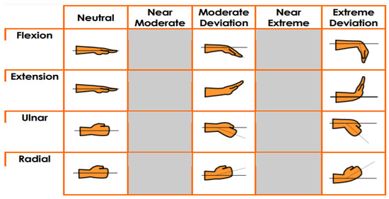
Figure 17.
Hand/wrist-posture scale [23].
The optimal postural condition for joints such as the wrist is neutral, because muscle tension is potentially uncomfortable and can develop carpal tunnel syndrome [24]. While the wrist is flexed (bent toward the palm) or stretched (bent away from the palm), especially when applying force, this condition occurs [24]. The application of torque to the Rear Driveshaft task shows this incorrect posture.
The same assembly procedure also analyzed the shoulder (Figure 18) and lower-back posture (Figure 23). Only the moderate condition was identified for these.
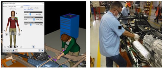
Figure 18.
Shoulder-posture simulation (non-immersive).
As a reference, Figure 19 shows the shoulder-posture scale adapted from a general ergonomics industry guideline [23].
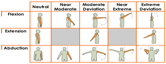
Figure 19.
Shoulder-posture scale [23].
The lower-back analysis helps evaluate the spinal forces acting on a virtual human’s lower back under any posture and loading condition (Figure 20). Thus, it is possible to determine whether newly defined or existing workplace tasks exceed NIOSH threshold limit values or expose workers to an increased risk of lower-back injury [25]. This analysis could be used to evaluate the risks of lower-back injuries in existing tasks.
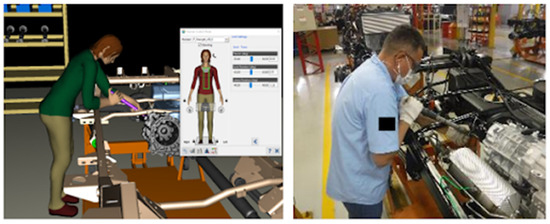
Figure 20.
Lower-back-posture simulation (non-immersive).
Figure 21 shows the lower-back-posture scale adapted from a general ergonomics industry guideline [23].
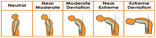
Figure 21.
Lower-back-posture scale [23].
The next simulation was of a radiator assembly procedure, and the DHM shows that the knee flexion is nearly at its extreme limits, with a deviation of 130.4 degrees on a scale ranging from −5 to 160.2 degrees (Figure 22).
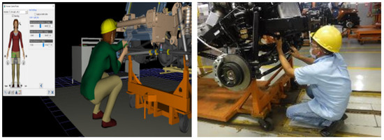
Figure 22.
Leg/knee-posture simulation (non-immersive).
In virtual simulation, the radiator hose-clamp assembly presented a potential critical ergonomics risk. Because the worker must squat to connect the clamp to the radiator hose, it is related to lower-limb posture. It is a high-risk posture for musculoskeletal problems involving joints, most particularly the knee.
Analysis of leg stresses allows identifying issues related to the leg. Studies identified three critical areas regarding the leg postures. The position follows the same criteria regarding flexion (neutral, moderate deviation, and extreme deviation) [23].
In this assembly procedure, VR analysis was performed to better understand the worker’s postural condition in an immersive assessment (Figure 23). We observed that after the hose is attached to the back of the radiator and no other access is available, this is a blind operation.
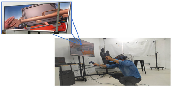
Figure 23.
Radiator hose-clamp simulation (immersive).
Finally, a simulated parking-brake assembly was performed. This simulation, like the previous ones, began with DHM. In this assembly procedure, the worker must pick up the portable nutrunners and device to support adjust, access the vehicle, and sit on the vehicle seat while applying torque to the brake lever. The worker’s trunk-twist movement was observed in order to see the screw and complete the torque for this task.
When the worker rotates the trunk to complete the task, the trunk musculature must work to overcome the body tissues’ passive resistance. The passive resistance is low in the neutral position, and the trunk can be twisted in either direction [23]. Even if the worker’s lateral rotation deviation is in the middle, flexion of 60 degrees on a scale of −52 to 84 degrees is required to apply the torque in the brake lever (Figure 24).
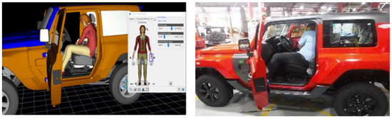
Figure 24.
Parking brake adjustment-posture simulation (non-immersive).
Figure 25 shows the trunk twist-posture scale adapted from a general ergonomics industry guideline [23].
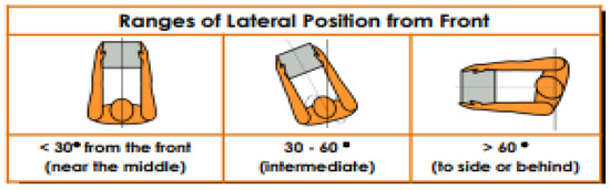
Figure 25.
Trunk twist-posture scale [23].
Much like the previous assembly procedures, VR was used to analyze how items like the seat and center console could affect the worker’s vision during the task (Figure 26).
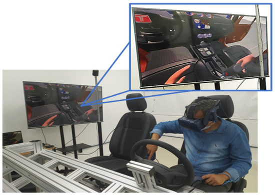
Figure 26.
Trunk twist-posture scale (immersive).
We observed that even with the seat fully adjusted to the rear, it is impossible to view the screw and position the portable nutrunners without lumbar flexion. As a general rule, workers should have a limited exposure to all near-extreme or extreme posture conditions. In these conditions, a worker cannot do this for more than 50% of the operation cycle [23].
3.2. Validation of the Developed Method
The method was validated by comparing the current physical ergonomic analysis method (real) to our virtual proof of concept, which was generated with the Sue Rodgers Muscle Fatigue evaluation checklist as a guide. The virtual simulation considered VR and DHM analysis.
Sue Rodgers’ checklist serves as the foundation for this comparison. As an outcome, the specifics pertaining to the form’s concepts, as well as how the results are presented, are provided below.
Operations were split into tasks and determined for what percent of the shift each task is completed. Next, we analyzed the primary tasks performed and rated, from 1 to 4, each task (low, moderate, high, and very high) and body region according to three risk factors (effort level, continuous effort duration, and effort frequency).
Typically, a worksheet is used to carry out the assessment ratings for each category, as shown in Table 1, adapted from [26].

Table 1.
Body part effort level Categories.
The continuous effort duration (Table 2) is spent in constant muscle activity without a break at the second step rate. It is measured for each body part/effort level identified in Step 1. There are 4 rating levels for a duration based on the time in seconds, adapted from [26].
Table 2.
Muscular Contraction in seconds.
The next step rates the frequency or number of efforts per minute. Frequency is evaluated (counted) for each body part/effort level identified in Step 1. There are 4 rating levels for frequency, as shown in Table 3, adapted from [26].
Table 3.
Effort Frequency per minute.
Last, once the ratings from 1 to 4 for effort level, duration, and frequency for each body part are determined, the body part is classified as a level of priority for change: low, moderate, high, and very high, adapted from [26]. This classification reflects the potential for muscle fatigue and is derived from Table 4.
Table 4.
Effort Level.
- Tasks are scored in the following order:
- ●
- Tasks with any rating of 4 are classified as very high priority for change regardless of the other two rating values.
- ●
- Tasks with a priority for change score of moderate and above are considered to be at an elevated risk for injury.
Since the duration and frequency are no different from physical or virtual simulation assembly procedures, the worker effort (impacted by posture) was a critical point to define the level of priority for change and compare the methods (physical vs. virtual).
The Sue Rodgers assessment was performed for four assembly procedures; however, one assembly procedure was chosen as an example to demonstrate a comparison completed using the two different methods (Figure A1).
According to the Sue Rodgers concept, the different ergonomic conditions for each body part (neck, shoulder, back, etc.) were assessed in all tasks of the Rear Driveshaft assembly procedures in Figure A1. The tasks were then classified, and the results of the physical and virtual assessments were tabulated so they could be compared.
As noted previously, an original checklist designed by Sue Rodgers shows the numerical result of the risk priority of each of the assessed tasks in the last columns. To facilitate comparison, the last columns were duplicated and named physical and virtual (highlighted in orange in Figure A1). The results of the two analyses were identical, with the same risk priority score calculated by Sue Rodgers for all assembly procedures.
Similar results were found from the analysis of attributive characteristics, such as hand clearance and strength, not covered by the Sue Rodgers checklist by comparing physical observation and virtual reality analysis.
3.3. Proposed Design Guidelines
We compiled our observations into guidelines, which are phrased as generalized suggestions regarding behavior in specific situations, and formatted as statements, following the design science research principles regarding guidelines artifacts [27]. Table 5 lists the proposed design guidelines.
Table 5.
Design guidelines for intuitive VR authoring tools.
4. Conclusions
Anthropometry (i.e., body measures) can significantly influence how workers interact with parts and tools during task execution. The percentile 50th adopted in these simulations that are representative of this industry population is based on the analyses performed. For other applications it needs to be considered a specific percentile required.
We found that our proof of concept of physical ergonomics analysis in the manufacturing process, based on virtual simulations, presents a similar performance to physical methods, where the analyses are performed by observing the reality of the process. The worker effort, impacted by posture and final risk priority score, was the same for both methods, as well as analysis of attributive of hand clearance and strength.
The Sue Rodgers checklist (Figure A1) presented individual scores (1 to 4) for the three risk factors (effort level, continuous effort duration, and effort frequency) for each task and body part in both the “real” and “virtual” assessments. Given the high similarity in results between the methods, the virtual approach demonstrates potential as an excellent alternative for reducing correction time and costs, while also decreasing worker exposure to ergonomic risks.
Therefore, our ergonomic analysis based on virtual reality and digital human modeling can be an important ergonomic analysis method applied to product development phases for early discovery of failure or issues, and it can significantly reduce the costs spent to change products post-launch. It also avoids exposing the employee to injuries and improves workplace well-being. Thus, it can be an important ergonomic analysis method that could be applied to product development phases to detect failure or issues early on and significantly reduce the costs spent to change products post-launch.
Our proof of concept used percentiles that represented 90% of the population under study. In addition, activities involving ergonomic risk factors associated with tactile perception, temperature changes, or dimensions are not covered in our experiment. Activities involving ergonomic risk factors such as tactile perception, temperature changes, or dimensions cannot be addressed with this method and must include additional elements, such as wearable devices, which can serve as a starting point for future research.
Author Contributions
Validation, M.d.S.H.; Investigation, C.S.S.; Writing—original draft, A.G.S., R.V.M., L.G.G.d.A., C.S.S., M.d.S.H. and M.V.M.G.; Writing—review & editing, R.V.M., L.G.G.d.A., M.F.C., C.S.S. and I.W.; Supervision, I.W.; Project administration, A.G.S. All authors have read and agreed to the published version of the manuscript.
Funding
This research received funding from Bahia State Research Support Foundation (FAPESB).
Institutional Review Board Statement
Not applicable.
Informed Consent Statement
Not applicable.
Data Availability Statement
The original contributions presented in this study are included in the article. Further inquiries can be directed to the corresponding author.
Acknowledgments
The authors thank the SENAI CIMATEC University, and the National Council for Scientific and Technological Development; IW is a DT-1D productivity grant fellow (308783/2020-4).
Conflicts of Interest
The authors declare no conflicts of interest.
Appendix A
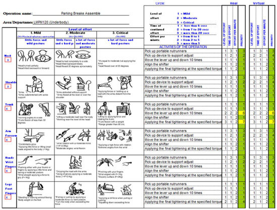
Figure A1.
Sue Rodgers checklist [26].
References
- Ma, H.; Cao, W.; Cheng, X.; Wang, C.; Wang, K. Value Creation and Sustainable Project Management: A Case Study on a Leading SOE in China. J. Cases Inform. Technol. 2023, 25, 1–16. [Google Scholar] [CrossRef]
- Failure Mode and Effects Analysis (FMEA), Why Perform Failure Mode and Effects Analysis (FMEA). 2021. Available online: https://quality-one.com/fmea (accessed on 18 July 2021).
- Naranjo, J.E.; Mora, C.A.; Bustamante Villagómez, D.F.; Mancheno Falconi, M.G.; Garcia, M.V. Wearable Sensors in Industrial Ergonomics: Enhancing Safety and Productivity in Industry 4.0. Sensors 2025, 25, 1526. [Google Scholar] [CrossRef] [PubMed]
- Fabio, G.; Margherita, P.; Luca, Z.; Marcello, P. An Automatic Procedure Based on Virtual Ergonomic Analysis to Promote Human-Centric Manufacturing. Procedia Manuf. 2019, 38, 488–496. [Google Scholar] [CrossRef]
- Jerald, J. The VR Book: Human-Centered Design for Virtual Reality; Morgan & Claypool: San Rafael, CA, USA, 2015. [Google Scholar]
- Hu, B.; Ma, L.; Zhang, W.; Salvendy, G.; Chablat, D.; Bennis, F. Predicting Real-World Ergonomic Measurements by Simulation in a Virtual Environment. Int. J. Ind. Ergon. 2011, 41, 64–71. [Google Scholar] [CrossRef]
- He, Q.; Li, L.; Li, D.; Peng, T.; Zhang, X.; Cai, Y.; Zhang, X.; Tang, R. From Digital Human Modeling to Human Digital Twin: Framework and Perspectives in Human Factors. Chin. J. Mech. Eng. 2024, 37, 9. [Google Scholar] [CrossRef]
- Lei, Y.; Su, Z.; He, X.; Cheng, C.; Lei, Y.; Su, Z.; He, X.; Cheng, C. Immersive Virtual Reality Application for Intelligent Manufacturing: Applications and Art Design. Math. Biosci. Eng. 2023, 20, 4353–4387. [Google Scholar] [CrossRef] [PubMed]
- Raschke, U.; Cort, C. Siemens Jack. In DHM and Posturography; Scataglini, S., Paul, G., Eds.; Academic Press: Cambridge, MA, USA, 2019; pp. 35–48. [Google Scholar]
- da Silva, A.G.; Mendes Gomes, M.V.; Winkler, I. Virtual Reality and Digital Human Modeling for Ergonomic Assessment in Industrial Product Development: A Patent and Literature Review. Appl. Sci. 2022, 12, 1084. [Google Scholar] [CrossRef]
- Coelho, H.; Monteiro, P.; Gonçalves, G.; Melo, M.; Bessa, M. Immersive Creation of Virtual Reality Training Experiences. IEEE Access 2024, 12, 85773–85782. [Google Scholar] [CrossRef]
- Gregor, S.; Hevner, A.R. Positioning and Presenting Design Science Research for Maximum Impact. MIS Q. 2013, 37, 337–355. [Google Scholar] [CrossRef]
- Page, M.J.; McKenzie, J.E.; Bossuyt, P.M.; Boutron, I.; Hoffmann, T.C.; Mulrow, C.D.; Shamseer, L.; Tetzlaff, J.M.; Akl, E.A.; Brennan, S.E.; et al. The PRISMA 2020 Statement: An Updated Guideline for Reporting Systematic Reviews. BMJ 2021, 372, n71. [Google Scholar] [CrossRef] [PubMed]
- Booth, A.; Martyn-St James, M.; Clowes, M.; Sutton, A. Systematic Approaches to a Successful Literature Review; SAGE Publications: Thousand Oaks, CA, USA, 2021; pp. 1–100. [Google Scholar]
- FORD Motor Company, Occupational Safety Department. Global Ergonomic Assessment. In South America Manufacturing Ergonomic Report; FORD Motor Company: Detroit, MI, USA, 2020; pp. 8–9. [Google Scholar]
- Jack, a Premier Human Simulation Tool for Populating Your Designs with Virtual People and Performing Human Factors and Ergonomic Analysis. Available online: https://www.plm.automation.siemens.com/media/store/de_de/4917_tcm1023-4952_tcm38-1992.pdf (accessed on 26 May 2025).
- Zhu, W.; Fan, X.; Zhang, Y. Applications and Research Trends of Digital Human Models in the Manufacturing Industry. Virtual Real. Intell. Hardw. 2019, 1, 558–579. [Google Scholar] [CrossRef]
- TECNOMATIX. Process Simulate. Available online: https://blogs.sw.siemens.com/tecnomatix/tecnomatix-16 (accessed on 18 October 2021).
- Joseph, B.S. Ford Motor Company Global Ergonomics Process. Proc. Hum. Factors Ergon. Soc. Annu. Meet. 2000, 44, 2–454. [Google Scholar] [CrossRef]
- Creswell, J.W.; Creswell, J.D. Research Design: Qualitative, Quantitative, and Mixed Methods Approaches; Sage Publications: Thousand Oaks, CA, USA, 2017. [Google Scholar]
- Grajewski, D.; Górski, F.; Zawadzki, P.; Hamrol, A. Application of Virtual Reality Techniques in Design of Ergonomic Manufacturing Workplaces. Procedia Comput. Sci. 2013, 25, 289–301. [Google Scholar] [CrossRef]
- Peruzzini, M.; Pellicciari, M.; Gadaleta, M. A Comparative Study on Computer-Integrated Set-Ups to Design Human-Centred Manufacturing Systems. Robot. Comput.-Integr. Manuf. 2019, 55, 265–278. [Google Scholar] [CrossRef]
- TDI. Ergonomics for General Industry General Industry. Available online: https://www.abergo.org.br (accessed on 11 July 2021).
- Cudlip, A.C.; Holmes, M.W.R.; Callaghan, J.P.; Dickerson, C.R. The Effects of Shoulder Abduction Angle and Wrist Angle on Upper Extremity Muscle Activity in Unilateral Right Handed Push/Pull Tasks. Int. J. Ind. Ergon. 2018, 64, 102–107. [Google Scholar] [CrossRef]
- Bortolini, M.; Faccio, M.; Gamberi, M.; Pilati, F. Motion Analysis System (MAS) for Production and Ergonomics Assessment in the Manufacturing Processes. Comput. Ind. Eng. 2020, 139, 105485. [Google Scholar] [CrossRef]
- Rodgers, S.H. Muscle Fatigue Assessment: Functional Job Analysis Technique. In Handbook of Human Factors and Ergonomics Methods; CRC Press: Boca Raton, FL, USA, 2004. [Google Scholar]
- Offermann, P.; Blom, S.; Schönherr, M.; Bub, U. Artifact Types in Information Systems Design Science–A Literature Review. In Global Perspectives on Design Science Research; Winter, R., Zhao, J.L., Aier, S., Eds.; Springer: Berlin/Heidelberg, Germany, 2010; pp. 77–92. [Google Scholar]
Disclaimer/Publisher’s Note: The statements, opinions and data contained in all publications are solely those of the individual author(s) and contributor(s) and not of MDPI and/or the editor(s). MDPI and/or the editor(s) disclaim responsibility for any injury to people or property resulting from any ideas, methods, instructions or products referred to in the content. |
© 2025 by the authors. Licensee MDPI, Basel, Switzerland. This article is an open access article distributed under the terms and conditions of the Creative Commons Attribution (CC BY) license (https://creativecommons.org/licenses/by/4.0/).