Review

Recent Developments in Additively Manufactured Crash Boxes: Geometric Design Innovations, Material Behavior, and Manufacturing Techniques

1
College of Engineering and Technology, American University of the Middle East, Egaila 54200, Kuwait
2
Mechanical Engineering Department, Arab Academy for Science and Technology and Maritime Transport (AASTMT), Alex 19838, Egypt
3
Mechanical Engineering Department, College of Engineering, Alexandria University, Alex 21526, Egypt
*
Author to whom correspondence should be addressed.
Appl. Sci. 2025, 15(13), 7080; https://doi.org/10.3390/app15137080 (registering DOI)
Submission received: 5 May 2025 / Revised: 24 May 2025 / Accepted: 2 June 2025 / Published: 24 June 2025
(This article belongs to the Section Additive Manufacturing Technologies)

Abstract

Crash boxes play a vital role in improving vehicle safety by absorbing collision energy and reducing the forces transmitted to occupants. Additive manufacturing (AM) has become a powerful method for developing advanced crash boxes by enabling complex geometries. This review provides a comprehensive examination of recent progress in AM crash boxes, with a focus on three key aspects: geometric design innovations, material behavior, and manufacturing techniques. The review investigates the influence of various AM-enabled structural configurations, including tubular, origami-inspired, lattice, and bio-inspired designs, on crashworthiness performance. Among these, bio-inspired structures exhibit superior energy absorption characteristics, achieving a mean specific energy absorption ( S E A ) of 21.51 J/g. Material selection is also explored, covering polymers, fiber-reinforced polymers, metals, and multi-material structures. Metallic AM crash boxes demonstrate the highest energy absorption capacity, with a mean S E A of 28.65 J/g. In addition, the performance of different AM technologies is evaluated, including Stereolithography (SLA), Material Jetting (MJT), Selective Laser Melting (SLM), Selective Laser Sintering (SLS), Fused Deposition Modeling (FDM), and hybrid manufacturing techniques. Among these, crash boxes produced by SLM show the most favorable energy absorption performance, with a mean S E A of 16.50 J/g. The findings presented in this review offer critical insights to guide future research and development in the design and manufacturing of next-generation AM crash boxes intended to enhance vehicle safety.

1. Introduction

Vehicle manufacturers continuously strive to develop vehicles with enhanced performance and improved safety features. In recent decades, passenger safety has become an increasingly important focus. For example, despite the fact that there were more registered cars in the US by approximately 30% between 1990 and 2013, the annual traffic accident-related fatality rate decreased by around 32% over the same period [1]. A fundamental factor in mitigating the impact of accidents is the structural design of the vehicle. The ability of a vehicle’s structure to absorb dynamic energy and reduce passenger injuries in the event of accidents is referred to as crashworthiness, also known as passive safety [2]. Located between the side rails and the bumper, as illustrated in Figure 1, the crash box plays a critical role in enhancing a vehicle’s crashworthiness. In case of accidents, the crash box is designed to absorb dynamic energy, thereby preventing structural damage to other components of the vehicle.
Crash boxes are traditionally manufactured using methods such as extrusion [3,4,5], stamping [6,7], welding [8,9], wire erosion [10,11,12], CNC water jet cutting [13], and composite processing [14], which restrict the design to relatively simple geometries. This limitation hinders efforts to improve crashworthiness, as it prevents the use of more advanced and efficient designs. Because of this, interest is rising in more sophisticated techniques such as additive manufacturing (AM), sometimes referred to as 3D printing, Solid Free Form (SFF), or Rapid Prototyping (RP). The concept of AM was first introduced by Charles Hull in 1984 [15]. By fabricating materials layer by layer, AM makes it possible to create intricate structures [16]. Unlike traditional manufacturing methods, AM offers increased design freedom, allowing the creation of more creative structures that maximize mechanical properties. This flexibility makes AM particularly suited for producing intricate, high-performance crash box designs [17].
While several review papers have examined crash box designs and their manufacturing techniques [18,19,20,21,22], there remains a significant gap in comprehensively assessing the transformative potential of AM in this domain. This paper provides an in-depth exploration of how AM technologies are revolutionizing crash box development. It highlights key design innovations, material advancements, and manufacturing techniques that enhance energy absorption and overall vehicle safety. The categorization of additively manufactured crash boxes is summarized in Figure 2, with detailed discussions in the following sections.
This paper is organized as follows: Section 2 provides an overview of the working principle of crash boxes. Section 3 discusses various performance metrics for crash boxes, which are essential for evaluating their effectiveness. Section 4 introduces the AM process, outlining the key steps involved in producing components using AM technologies. Section 5 delves into the prominent AM techniques used for crash box manufacturing, dividing them into three categories: liquid-based, powder-based, and solid-based methods. Section 6 explores the different geometric designs used in additively manufactured crash boxes, categorizing them into tubular, origami-inspired, lattice, and bio-inspired structures. Section 7 focuses on the materials used in the AM of crash boxes, discussing the properties and performance of polymers, fiber-reinforced polymers, metals, and multi-material structures. In Section 8, this paper reviews the specific AM techniques employed for crash box production. Finally, Section 9 concludes the paper, summarizing the key findings and future directions.

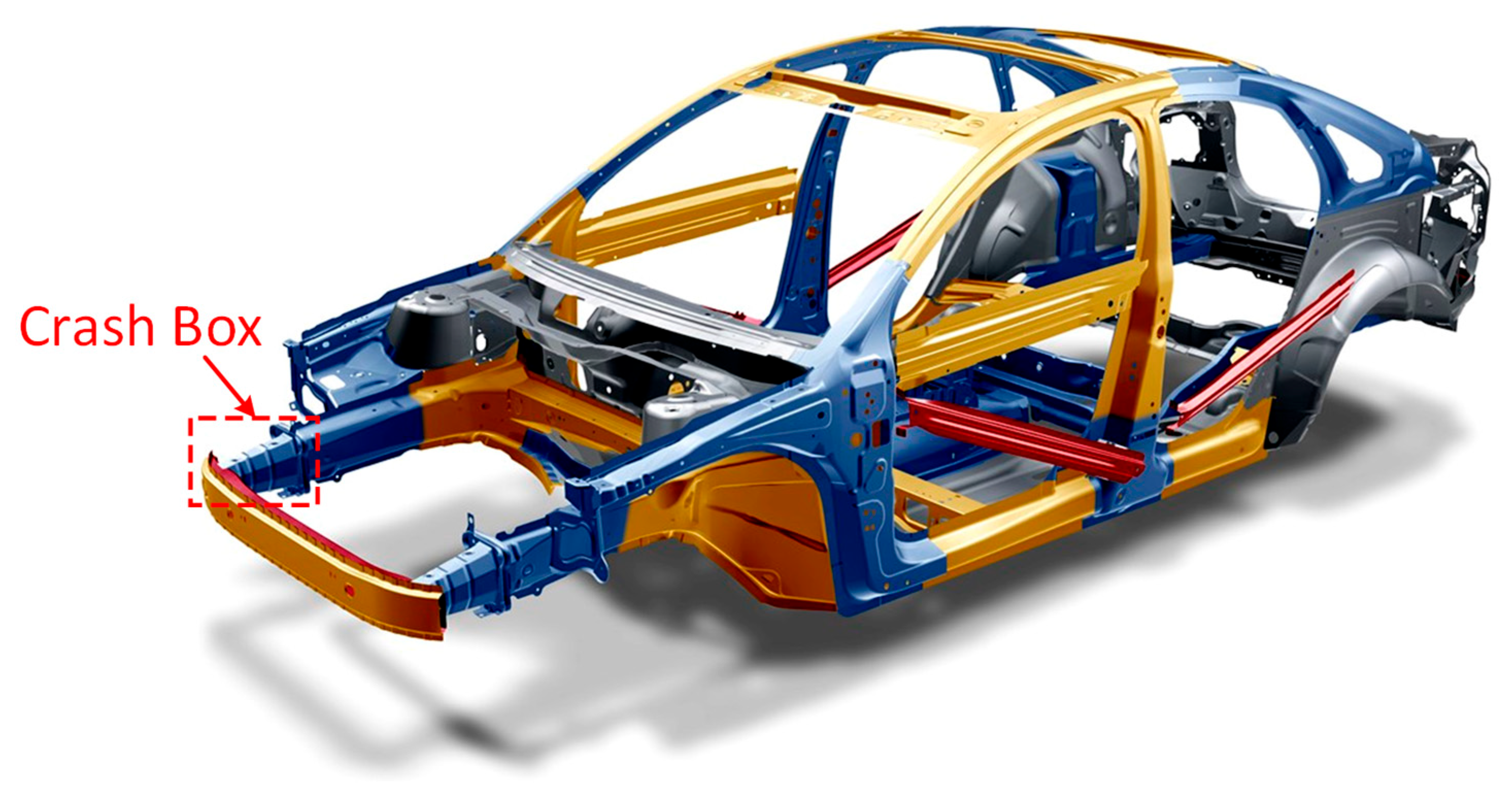
2. Crash Box Working Principle

Impact energy absorption is generally achieved through three mechanisms: frictional dissipation [23]; shear and fracture failure [24]; and plastic deformation [25]. Frictional dissipation occurs when relative movement between contacting surfaces converts kinetic energy into heat, which is influenced by surface roughness and contact forces. Shear and fracture failure involve localized material cracking and separation, where energy is absorbed through crack initiation and propagation, which are governed by material fracture toughness and strain rate sensitivity. Plastic deformation involves the irreversible reshaping of the material under stress, where energy is absorbed through permanent structural changes beyond the elastic limit [26]. The extent of energy absorption is governed by both the geometrical configuration and the material properties of the crash box [27]. Plastic deformation is the most widely utilized energy absorption mechanism in crash boxes [18]. A typical crash box exposed to axial crushing is shown in Figure 3.

3. Crash Box Performance Metrics

The effectiveness of a crash box is evaluated using several performance metrics that quantify its ability to mitigate crash forces and minimize damage to both the vehicle and its occupants. These metrics are typically derived from the force–displacement diagram, which provides insights into the crash box’s energy absorption characteristics. Figure 4 presents a typical force–displacement diagram for a crash box going through axial crushing. To describe the characteristics of energy absorption, the parameters below are considered [29].

3.1. Total Energy Absorption, E T

The total energy absorption ( E T ) of a crash box can be determined by calculating the work done by the crushing force. This is represented by the area under the axial force versus the axial displacement curve, as illustrated in Figure 4. E T is expressed as follows:
E T = 0 δ m a x F d δ
where F is the crushing force, δ is the displacement, and δ m a x is the total crush displacement.

3.2. Peak Crush Force, P C F

The peak crush force ( P C F ) , as illustrated in Figure 4, is the maximum force observed in the axial direction during the crushing process.

3.3. Mean Crush Force, M C F

The mean crush force ( M C F ) is defined as the total energy absorbed per unit of total crush displacement. It is expressed as follows:
M C F = 0 δ m a x F d δ δ m a x
where F is the crushing force, δ is the displacement, and δ m a x is the total crush displacement.

3.4. Specific Energy Absorption, S E A

The specific energy absorption ( S E A ) is defined as the total energy absorbed per unit mass of the crash box. It is expressed as follows:
S E A = E T m
where E T is the total energy absorption and m is the mass of the crash box.
A higher S E A value indicates greater energy absorption per unit mass, which in turn reduces the kinetic energy transferred to the passenger, thereby enhancing occupant safety [28].

3.5. Crush Force Efficiency, C F E

Crush force efficiency ( C F E ) is defined as the ratio of the M C F to the P C F . It is expressed as follows:
C F E = M C F P C F
For crashworthiness, a high value of CFE indicates a low peak crushing force, which results in reduced force being transferred to the passenger, thereby enhancing safety [28].

4. AM Process

Using AM technology to produce a component typically follows a sequence of seven essential steps, as shown in Figure 5, which apply universally across different AM techniques [30]. After the conceptual development of the idea, the AM process starts with creating a 3D digital model for the structure, which can be generated using 3D CAD software. The accuracy of this model is crucial because it has a direct impact on the finished product’s quality. Several factors, such as geometric limitations and the need for support material, must be considered at this stage. Once the 3D CAD file is ready, it is converted into a Standard Tessellation Language (STL) file format, which simplifies the design by representing the object’s surface with triangles. The 3D digital model is then transformed into G-Code, a programming language used to operate 3D printers, by importing the STL file into slicer software. The slicer software divides the model into layers and defines key printing parameters, including layer height, printing speed, and the layout of support structures. Once the file is prepared, the object is manufactured using the chosen 3D printing technology. After the printing process is complete, any support structures must be removed. For certain technologies, removing supports might only require separating the printed component from the build plate; for others, more intricate procedures would be needed. Finally, post-processing is often necessary to enhance the mechanical properties and surface quality of the printed part. Common techniques include post-heat treatment, which is employed to relieve residual stresses induced during the printing process and to refine the microstructure. Additionally, surface polishing or chemical smoothing is frequently used to reduce surface roughness and improve the overall finish of the component.

5. AM Processes

Various AM processes are available, each with unique benefits and limitations. The choice of a specific AM technique is affected by parameters like the material, processing speed, resolution, cost-effectiveness, and the performance requirements of the product. Based on the initial state of the printing material, AM techniques are broadly divided into three categories: liquid-based, powder-based, and solid-based methods [31]. Within each category, different techniques have been developed to meet diverse applications. The most prominent AM techniques commonly used in crash box manufacturing are outlined below.

5.1. Stereolithography (SLA)

Stereolithography (SLA) was among the first AM techniques, and it was created by Charles Hull in 1984 [15]. SLA is a liquid-based AM technique. As shown in Figure 6a, the SLA system is composed of an ultraviolet (UV) laser source, a building platform, and a tank full of liquid photoresin. The liquid located in the tank is polymerized by the UV laser beam. To create the required pattern, the laser beam is directed through the tank’s transparent glass while being manipulated by mirrors. The laser is used to polymerize the patterned 2D layer, and depending on the system configuration, the platform is either raised or lowered to enable the polymerization of the next layer. The 3D part is created by repeating the process. Lastly, the unpolymerized photoresin liquid needs to be cleaned from the printed part [32]. This photopolymerization process results in a thermoset material formed through irreversible chemical crosslinking, which renders the printed parts non-re-meltable [33].
The key advantage of SLA is the printing parts’ high resolution. SLA printing has many drawbacks, including slow speed, high cost, and a limited selection of photopolymer liquids. The potential toxicity of the photopolymer liquid is a further concern [17].

5.2. Material Jetting (MJT)

Material Jetting (MJT) was introduced in 1999 [17]. MJT is a liquid-based AM technique. The MJT system generally includes one or more extruders equipped with a nozzle, a UV light source, and a build platform as illustrated in Figure 6b. The first step is to heat the photoresin liquid, which is then deposited as hundreds of microdroplets from the nozzle, creating a thin layer on the build platform. These droplets are rapidly polymerized by the UV light. After polymerizing a layer, a new layer of liquid is deposited onto the previous layer. Each subsequent layer is polymerized to complete the part [34]. The photopolymerization process in MJT similarly yields thermoset materials with irreversible chemical crosslinking, producing cured parts that cannot be re-melted [33].
The main advantage of MJT is being able to print with several materials simultaneously, which makes it possible to produce parts with a variety of characteristics. Furthermore, MJT is cost-effective and scalable for various production volumes. However, it also has several drawbacks, including the limited range of compatible photoresin liquids, poor mechanical and thermal properties, and concerns about the toxicity of the photoresin liquids [35].

5.3. Selective Laser Melting (SLM)

Selective Laser Melting (SLM), introduced in 1995, emerged as an alternative technology to SLA [36]. It is categorized as a powder-based AM technique. As shown in Figure 6c, the SLM system includes an XY scanning mirror, a laser source, a powder supply piston, a powder build piston, and a re-coater. A thin layer of powder is applied to the building platform by the re-coater. The powder is then scanned by a laser, which follows a specific trajectory that corresponds to the 3D design’s cross-section. When the laser moves, it melts the powder, causing it to fuse. Once a layer is complete, the powder build piston lowers slightly, and a fresh layer of powder is added. The part is constructed by fusing each new layer with the one before it. The completed 3D part is then revealed once the unused powder is removed. In order to minimize oxidation, the printing area is frequently flushed with argon or nitrogen gas during the SLM process. Several kinds of metals can be 3D printed with the SLM technique, including titanium, steel, aluminum, and nickel alloys [37].
SLM is ideal for complicated parts because it provides high-quality printing and precise resolution. A significant advantage is that the powder acts as a support structure, eliminating challenges in removing additional support material. However, SLM has its drawbacks, including high costs and slower processing times compared to other AM techniques [16].

5.4. Fused Deposition Modeling (FDM)

Fused Deposition Modeling (FDM), also referred to as Fused Filament Fabrication (FFF), is a solid-based AM technique. Developed in 1989, it is the most commonly used method in AM [36]. The FDM system typically includes a building platform, filament spools, and a heated extrusion nozzle, as shown in Figure 6d. After being passed from the filament spool to the heated extrusion nozzle, the thermoplastic filament melts and becomes semi-liquid. The melted material is then deposited layer by layer onto the building platform or previous layers, where it fuses and solidifies. This procedure is repeated until the part is constructed. Polymeric materials with low melting points, such as Polyethylene Terephthalate Glycol (PETG), Acrylonitrile Butadiene Styrene (ABS), polyamide (PA) which is also known as nylon, Polycarbonate (PC), thermoplastic polyurethane (TPU), Acrylonitrile Styrene Acrylate (ASA), and Polylactic Acid (PLA), are frequently used as filament basis materials in the FDM technique. Fiber-reinforced filaments have been created recently in order to enhance the filaments’ mechanical properties [17].
FDM printing’s restriction to thermoplastic polymers with appropriate melt viscosities is one of its disadvantages. The viscosity needs to be sufficiently low to allow for extrusion while still being sufficiently high to support the structure. Additionally, issues such as nozzle clogging can occur, particularly with fiber-reinforced filaments. Furthermore, products manufactured using the FDM technique often display anisotropic properties. Despite these limitations, FDM printing offers significant advantages, like high speed, low cost, and ease of use. An additional advantage of FDM printing is the capability to deposit different materials simultaneously by using several extrusion nozzles loaded with different filaments, which makes it possible to produce parts with a variety of characteristics [38].
Figure 6. Illustration of standard AM configurations: (a) SLA; (b) MJT; (c) SLM; (d) FDM [39].
Applsci 15 07080 g006
Table 1 summarizes the categories, materials, advantages, and disadvantages of the most prominent AM techniques commonly used in crash box manufacturing.

5.5. Other Techniques

It is important to note that additive manufacturing comprises seven primary processes, from which different techniques are derived. For instance, powder-based techniques include Selective Laser Sintering (SLS). SLS operates similarly to SLM, but instead of fully melting the material, SLS heats it to a temperature just below melting, enabling the powder particles to fuse. Polycaprolactone (PCL), TPU, and PA are thermoplastic polymers that are most frequently utilized in SLS. For specific uses, these thermoplastics can be filled with glass, ceramics, metals, or fiber elements [40]. Another AM technique is Jet Prototyping (JP), which is also known as Inject Printing. The processing components of JP are similar to those in SLS and SLM, as all three systems use powdered materials, powder beds, and mechanisms for powder management. However, JP differs in how it fuses particles. Instead of lasers, JP deposits a liquid binder through an injection nozzle onto the powder bed. This binder either physically or chemically bonds the powder particles, whereas SLS and SLM use laser-based fusion to bind the particles. JP printers are most commonly used for ceramics [32]. Another AM technology is the continuous fiber-reinforced FDM. Unlike conventional FDM, which relies on unreinforced or short-fiber-filled polymers, this technique strategically incorporates continuous fibers (carbon, glass, or Kevlar) to enhance the mechanical properties of the structure. This process involves simultaneously feeding continuous fibers and polymers into the extrusion nozzle, as shown in Figure 7. The nozzle heats the polymer beyond its melting point, while the fiber is preheated before entering the nozzle, ensuring its effective integration into the molten polymer within the extrusion system [41].

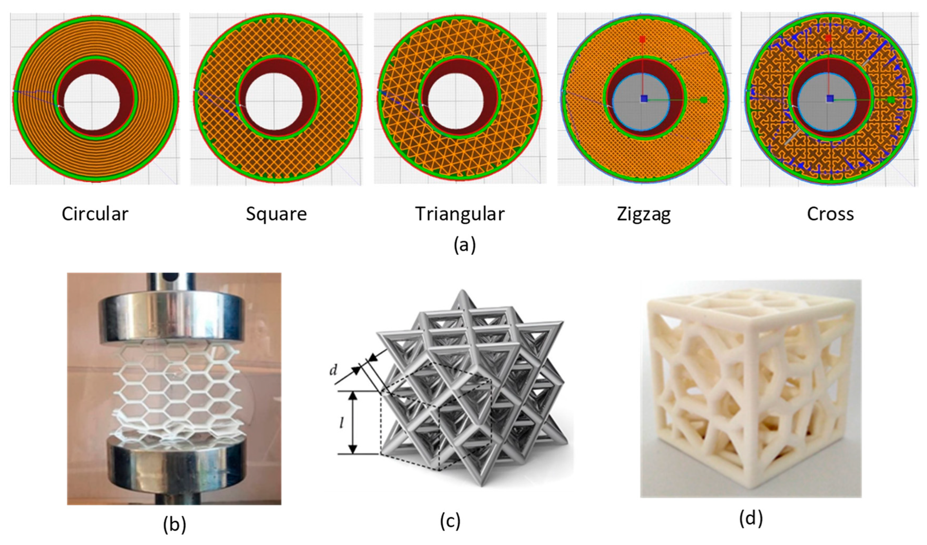
6. Geometries Used in Additively Manufactured Crash Boxes

In this section, 3D-printed crash boxes are classified into four main categories based on their geometric structural design: tubular structures, origami-inspired structures, lattice structures, and bio-inspired structures.

6.1. Tubular Structures

Tubular structures, available in either single- or multi-cell configurations, are a common design choice for crash boxes. These structures are engineered to deform progressively under axial loads, effectively dissipating dynamic energy during an impact [18]. AM offers a range of material options and provides an efficient fabrication process for tubular structures. Several investigations have examined tubular structures produced through AM [43,44,45].
Dharma Bintara and Agus Choiron [46] investigated carbon-fiber-reinforced PLA single-cell circular structures fabricated by using the FDM technique, as shown in Figure 8a, examining deformation patterns and E T . After testing wall thicknesses of 1.6, 1.8, and 2 mm, they found that E T increased with thickness, reaching 357.99 J at 2 mm, although fragmentation at the thickest wall indicated a trade-off between energy absorption and structural integrity. All specimens exhibit local buckling and discontinuous folding. While Dharma Bintara and Agus Choiron [46] focused on conventional single-cell circular tubes, Sun et al. [47] extended the study of single-cell tubular structures by introducing geometric modifications through corrugation, as shown in Figure 8b. They investigated shape memory corrugated tubes (SMCTs) fabricated from PLA/TPU blends using the FDM technique. The results reveal that the number of corrugations and their amplitude significantly influence the energy absorption capacity and recovery behavior. SMCTs demonstrate over 98% shape recovery within 20 s after thermal activation. After more than ten compression–recovery cycles, S E A values stabilize in the corrugated tubes, while straight tubes show a continuous decline.
Multi-cell tubular structures have attracted significant attention due to their superior performance, offering enhanced energy absorption capabilities and stable deformation under loading conditions compared to single-cell structures. These characteristics make them highly suitable for crash box applications. Tunay and Bardakci [48] investigated multi-cell tubes featuring concentric corner-edge connections in square and hexagonal cross-sections, as shown in Figure 8c. Manufactured from PLA+ and ABS materials using FDM, their results show that increasing the number of internal corners enhances energy absorption, with PLA+ tubes outperforming ABS. Specifically, tubes with S-WW and H-WW geometries demonstrated significantly higher S E A values compared to other geometries. These findings align with Wang et al. [49], who investigated multi-cell-filled tubes with different internal cell geometries—circular, hexagonal, and triangular—fabricated from carbon-fiber-reinforced PA using FDM as shown in Figure 8d. Their results show that higher filling densities significantly improve S E A , with circular-filled configurations achieving higher S E A values than the hexagonal and triangular variants. Liu et al. [50] further advanced the study of multi-cell tubular structures by investigating stepwise graded multi-cell tubes (SGMTs) and continuous graded multi-cell tubes (CGMTs), as illustrated in Figure 8e. The specimens are fabricated using carbon-fiber-reinforced PA filaments via the FDM technique. The results showed that the stepwise graded multi-cell tubes exhibited distinct multi-stage deformation during axial compression, with the S E A displaying an upward trend as the number of stepwise segments increased. Additionally, for the same range of cross-sectional variations, the continuous graded multi-cell tubes developed more plastic hinges and demonstrated superior energy absorption performance, which was attributed to the absence of discontinuous interfaces.

6.2. Origami-Inspired Structures

Origami-inspired structures, also known as pre-folded structures, are innovative designs that incorporate intricate folding patterns to enhance the energy absorption capacity of crash boxes, drawing inspiration from the ancient Japanese art of paper folding. These structures offer several advantages over traditional designs, including reduced P C F values, high energy absorption efficiencies, and stable deformation behaviors [21]. Origami-inspired structures, especially multi-cell origami designs, are challenging to produce due to their intricate geometries and complex folding patterns, which are difficult to replicate using traditional manufacturing methods. AM provides a viable solution that accommodates the complex shapes and fine details required in origami-inspired designs, enabling the precise fabrication of such detailed structures. Several investigations have focused on origami-inspired structures developed through AM [51,52,53].
Li et al. [54] proposed an origami crash box (OCB), shown in Figure 9a, fabricated using the FDM technique with carbon-fiber-reinforced nylon (PATH-CF15) material. Various geometrical configurations are generated using the Latin Hypercube Sampling (LHS) method to train an Artificial Neural Network (ANN) model designed to forecast the performance of the OCB. The results revealed that the highest difference in P C F between ANN predictions and experimental findings is 19.9%, while the highest difference in E T is 27.5%.
Because of their high energy absorption capacity and lightweight nature, multi-cell structures are frequently utilized in energy-absorbing applications. However, these structures can generate high P C F , posing risks to passenger safety during crashes. To address the issue, Qiu et al. [55] proposed origami-inspired multi-cell tubes fabricated from 316L stainless steel using SLM, with the printed specimens shown in Figure 9b. Their study demonstrates that web-to-web (W2W) designs achieved the highest S E A , while web-to-corner (W2C) designs offered superior deformation modes and lower P C F . Building on the multi-cell concepts, Xiao et al. [56] introduced double-layer biomimetic multi-cell tubes with pre-folded external walls, shown in Figure 9c, fabricated using SLM with stainless steel 316L. By varying parameters such as the number of cell elements, wall thickness, folded segments, folded edges, and cell patterns, they found that structures with eight edges and four-fold segments significantly enhanced both S E A and P C F performance.

6.3. Lattice Structures

Lattice structures are periodic, porous configurations that consist of systematically arranged 2D or 3D unit cells. According to studies, these structures are lightweight and have superior energy absorption capabilities, which makes them ideal for use in crash box designs [57]. Lattice structures are challenging to produce through traditional manufacturing techniques due to their intricate geometries and complex internal networks, which often require precision at a fine scale. AM techniques offer a suitable alternative by enabling the construction of these intricate forms. Several investigations have focused on lattice structures fabricated via AM [58,59,60].
Lattice structures are widely used as energy absorbers due to their reliable mechanical properties. Lin et al. [61] introduced symmetry-corrugate hierarchical honeycombs (SCHHs), shown in Figure 10a, fabricated from stainless steel 316L via SLM. The study investigated the effects of amplitude coefficients (φA) and period coefficients (φT) on crashworthiness, revealing that φT had a more pronounced influence on crash performance than φA. SCHH structures achieved a 53.8% improvement in E T compared to conventional honeycombs.
Graded lattice structures feature systematic variations in internal geometry within the same part, allowing for tailored mechanical performance and optimized energy absorption. Li et al. [62] introduced a novel graded origami-inspired lattice structure, illustrated in Figure 10e, fabricated from stainless steel 304 L using SLM. The S E A values across different orientations and geometries were recorded as 9.53 J/g for X-0.85-60, 4.63 J/g for Y-0.85-60, 9.08 J/g for Z-0.85-60, 7.15 J/g for Z-0.65-60, and 7.68 J/g for Z-0.85-50. Among graded configurations, G-50-65-50 achieved 10.89 J/g, G-65-50-65 reached 11.78 J/g, and G-50-65 exhibited the highest S E A at 13.08 J/g.
Auxetic lattice structures are promising for crash box design due to their unique deformation behavior and enhanced energy absorption capacity. Unlike traditional lattices, auxetic structures expand laterally when compressed, promoting superior distribution and dissipation of impact energy. Zhou et al. [63] investigated the energy absorption performance of three lattice types, hexagonal (non-auxetic), re-entrant (auxetic), and double arrowhead (auxetic), under axial and in-plane loading, as illustrated in Figure 10c. Specimens are fabricated using FDM with carbon-fiber-reinforced nylon (Onyx) and standard nylon. The results show that the double arrowhead auxetic structure exhibits the highest energy absorption capacity, achieving an S E A 125% higher than the hexagonal lattice and 244% higher than the re-entrant design when fabricated with Onyx.
Triply periodic minimal surface (TPMS)-based porous lattice structures have been attracting attention due to their excellent performance and lightweight characteristics. Wang et al. [64] introduced three novel composite TPMS-based porous structures, namely PI-type, PIP-type, and PN-type structures, as shown in Figure 10d, drawing inspiration from the micro-porous architecture of bones. These structures are produced from 316L stainless steel using SLM. The results show that deformation patterns and energy absorption capacities are strongly influenced by the thickness ratio between the inner and outer surfaces. PI structures with a thickness ratio of 0.4 (PI-0.4) demonstrate superior energy absorption capacity, achieving 10.8% and 12.1% improvements in E T and C F E , respectively, compared to conventional foams. Building upon interest in TPMS structures, Yin et al. [65] further investigated TPMS lattice structures and proposed a hierarchical structure based on TPMS inspired by natural biological architectures, as shown in Figure 10b. These hierarchical structures are fabricated from 316L stainless steel using SLM. The findings reveal that the S E A and P C F values of hierarchical structures are higher than those of non-hierarchical structures at the same density.
Lattice-filled multi-cell tubes combine the lightweight, tunable properties of lattice structures with the energy absorption and load distribution advantages of multi-cell designs, offering significant potential for enhanced crashworthiness. Liu et al. [66] investigated both assembled and integrated lattice-filled multi-cell tubes fabricated from carbon-fiber-reinforced PA using the FDM technique, as shown in Figure 10f. The study finds that the synergistic effect enhances E T by 55.6% and 83.8% for the assembled and integrated lattice-filled tubes, respectively, compared to the sum of empty multi-cell tubes and pure lattice structures.
Figure 10. Lattice structures: (a) symmetry-corrugate hierarchical honeycombs [61]; (b) hierarchical structure based on a triply periodic minimal surface [65]; (c) auxetic lattice structures [63]; (d) triply periodic minimal surface-based porous structures [64]; (e) graded origami-inspired lattice structures [62]; (f) lattice-filled multi-cell tubes [66].
Applsci 15 07080 g010

6.4. Bio-Inspired Structures

Animals and plants have adapted to harsh environments by optimizing their biological architecture throughout millions of years of evolution. These structures possess remarkable features, including lightweight construction and exceptional energy absorption capabilities. Bio-inspired structures are engineered designs that mimic the efficient characteristics of biological structures [20]. Bio-inspired structures often involve intricate designs that present substantial manufacturing challenges when using traditional methods. AM offers a suitable alternative, enabling the precise fabrication of these complex geometries. Several studies have focused on bio-inspired structures produced through AM [67,68,69,70].
Several studies have explored bio-inspired tubular structures, leveraging the capabilities of AM to realize complex designs that offer enhanced energy absorption performance. Cetin [71] proposed a thin-walled multi-cell tube with DNA-like helical ribs, fabricated from PLA using the FDM technique, as shown in Figure 11a. The study investigated various design parameters, such as spiral turns, inner diameter, and the number of spirals. The results demonstrated a significant increase in energy absorption, with S E A improving by 166.62% and C F E by 169.70% compared to a single-tube design. Chen et al. [72] drew inspiration from bamboo nodes to design Bionic Tubes with Bamboo Cross-section (BTBCs) and Bionic Tubes with Rib (BTRs), as shown in Figure 11b, manufactured from 316L stainless steel using the SLM technique. The study examined design parameters such as the number of inner tubes, tube diameter, number of ribs, rib location, and rib size. The results showed that BTBC-1 achieved the best S E A improvement with a 108.97% increase, while the best C F E improvement was observed in BTBC-2, which showed a 46.3% increase. Xiang et al. [73] proposed a bio-inspired thin-walled corrugated tapered tube modeled on the barnacle structure, as shown in Figure 11c. The specimens are produced using SLM with stainless steel 316L. The results indicate that the number of corrugations and the corrugation amplitude significantly affect the energy absorption capacity. The S E A of the corrugated tapered tube shows a 15.75% improvement over the traditional tapered tube. Building on their earlier work, Xiang et al. [74] further advanced the barnacle-inspired design by introducing hierarchical tapered tubes. Three design configurations are compared: the conventional tapered tube (CTT), the hierarchical tapered tube without corrugation (HTT), and the hierarchical corrugated tapered tube (HCTT), as shown in Figure 11d. The specimens are fabricated using SLM with 316L stainless steel. The results demonstrate that increasing the number of substructures significantly enhances the energy absorption capacity. The S E A of the HTT structure with four substructures achieves an 85.8% increase compared to the CTT structure.
Honeycomb lattice structures are recognized for their efficient energy absorption capacity, making them ideal for crashworthiness applications. Ha et al. [75] proposed a bio-inspired hierarchical circular honeycomb (BHCH) structure inspired by the natural architecture of wood and compared its performance to that of a conventional circular honeycomb (CH), as depicted in Figure 11e. The specimens, fabricated from nylon using FDM technology, revealed that the BHCH structure achieves a 45.3% improvement in S E A compared to the corresponding CH with an identical wall thickness. Extending the exploration of bio-inspired lattice structures, Khoa et al. [76] proposed five bio-inspired lattice structures, shown in Figure 11f, drawing inspiration from the arrangement of femur bones. The structures include a re-entrant honeycomb with a bio-inspired core (RE-BIO), a bio-inspired model with hierarchical subcells (BIO-HIERA), a bio-inspired design integrated with a honeycomb structure (BIO-HONEY), a bio-inspired design incorporating a re-entrant honeycomb (BIO-RE), and the baseline bio-inspired design (BIO). The specimens are fabricated from nylon using the FDM technique. The results demonstrate improvements in S E A , with BIO-RE achieving the highest improvement of 46.80%. However, the BIO-HONEY structure shows a reduction in S E A by 7.37%.
S E A serves as a key indicator of the crash box’s performance, reflecting the structure’s ability to absorb impact energy efficiently relative to its mass. Figure 12 presents the S E A values for additively manufactured crash box geometries, which are categorized into tubular, origami-inspired, lattice, and bio-inspired structures, as highlighted in recent studies. The mean S E A values for tubular, origami-inspired, lattice, and bio-inspired structures are 16.29 J/g, 15.29 J/g, 11.61 J/g, and 21.51 J/g, respectively. These results indicate that bio-inspired structures provide enhanced crashworthiness, whereas lattice structures may be less effective in absorbing impact energy. The standard deviation of S E A is highest for bio-inspired structures at 23.01 J/g, reflecting greater variability in energy absorption capabilities compared to the lattice structure at 12.67 J/g and origami-inspired structure at 12.46 J/g, while tubular structures demonstrate the most consistent performance at 8.75 J/g. This variability suggests that the energy absorption performance of bio-inspired designs can vary widely depending on the specific geometric features employed, while tubular structures tend to deliver more consistent and predictable energy absorption behavior. Notably, the limited number of studies on origami-inspired crash boxes highlights the need for further research to fully explore their energy absorption potential.

7. Materials Used in Additively Manufactured Crash Boxes

This section will focus on the various materials used in the AM of crash boxes. These materials can be classified into four main categories: polymers, fiber-reinforced polymers, metals, and multi-material.

7.1. Polymers

Polymers are widely employed in AM due to their versatility, cost efficiency, and adaptability across various AM techniques [16]. Moreover, polymers offer notable benefits, such as low weight and processing flexibility [77]. These properties render polymers ideal for applications requiring optimized energy absorption capacity, making them a desirable option for innovative crash box manufacturing. Multiple studies have examined polymer-based crash boxes produced through AM [78,79,80,81].
Recent studies have explored the influence of material selection and processing parameters on the crashworthiness of polymers used in additively manufactured crash boxes. Hidayat et al. [82] conducted a comprehensive study on thin-walled multi-cell tubular structures, illustrated in Figure 13a, analyzing the effects of wall thickness, filament material, and printing parameters such as layer height, printing speed, nozzle temperature, and nozzle diameter. The specimens were fabricated using FDM with three types of PLA: PLA+, PLA-ST, and PLA-LW. The highest C F E , reaching 0.91, was achieved using the PLA-ST filament, a wall thickness of 1.6 mm, a printing speed of 90 mm/s, a nozzle temperature of 230 °C, a 0.3 mm layer height, and a 0.8 mm nozzle diameter. For the maximum S E A of 19.08 J/g, the optimal setup included the PLA+ filament, a wall thickness of 1.6 mm, a printing speed of 90 mm/s, a nozzle temperature of 220 °C, a 0.3 mm layer height, and a 0.6 mm nozzle diameter. In a related study, Isaac et al. [83] investigated the performance of five polymer-based honeycomb lattice structures, shown in Figure 13b, fabricated using FDM with four polymer materials: PLA, PETG, ABS, ASA, and a fiber-reinforced material, PA12 with nano-carbon fiber. The results revealed that PETG and PLA achieve superior S E A values of 2.49 J/g and 2.6 J/g, respectively. PETG also exhibits the highest C F E at 0.83, followed by ABS at 0.78, highlighting PETG’s superior performance in both S E A and C F E .
Some studies have focused on the cyclic compression–recovery behavior of polymers used in additively manufactured crash boxes. For instance, Zhang et al. [84] investigated metamaterial lattice structures, shown in Figure 13c, fabricated using the FDM technique with PLA and PETG. The study examined unit-cell layouts, including hexagonal, hybrid, and re-entrant configurations. Under one-off compression, the PETG re-entrant honeycomb exhibited the best performance. During cyclic compression, the PETG re-entrant honeycomb demonstrated superior reusability, retaining approximately 40% of its energy dissipation capacity after seventeen cycles, which is two cycles more than the hybrid counterpart and five cycles more than the hexagonal counterpart. These findings further corroborate PETG’s superior performance, as noted in earlier studies.
Temperature is a critical factor influencing the mechanical properties of polymers employed in additively manufactured crash boxes. Chen et al. [85] investigated the effect of temperature on the performance of an origami crash box (OCB), illustrated in Figure 13d, fabricated from PLA using the FDM technique. The study evaluated the OCB at three temperatures: 30 °C, 40 °C, and 50 °C. The results revealed a clear temperature dependence, with S E A values of 1.88 J/g at 30 °C, 1.71 J/g at 40 °C, and 0.45 J/g at 50 °C, indicating a decline in S E A as temperature increases. This behavior is closely related to the glass transition temperature ( T g ) of PLA, which lies near the tested temperature range. As the material approaches or exceeds its T g , it transitions from a rigid, glassy state to a more rubbery and ductile state, resulting in a significant reduction in stiffness and energy absorption capacity. Consequently, a thorough understanding of the thermal properties of polymer materials, particularly their T g , is essential when evaluating or designing crashworthy components for varying operational environments.
Annealing is an effective post-processing technique for enhancing the crystallinity and mechanical properties of additively manufactured polymers by thermally reducing inter-layer defects. Hidayat et al. [86] investigated the performance of resin-coated 3D-printed thin-walled multi-cell structures (TWMCSs), shown in Figure 13e, fabricated from PLA using the FDM technique and coated with epoxy resin. Optimal S E A values were achieved by annealing at 80 °C for 40 to 120 min. The combined application of resin coating and annealing led to a 57% increase in S E A compared to untreated specimens.

7.2. Fiber-Reinforced Polymers

Polymers generally exhibit lower mechanical properties compared to metals. To enhance the performance of polymer structures, fibers, such as carbon fibers or glass fibers, are embedded within the polymer matrix [87]. This results in the formation of fiber-reinforced polymers that demonstrate improved mechanical properties [39]. A variety of studies have explored fiber-reinforced polymer crash boxes that are produced using AM techniques [88,89,90].
Wang et al. [91] investigated the energy absorption performance of additively manufactured thin-walled fiber-reinforced polymer tubes shown in Figure 14a. The tubes are manufactured using FDM with materials such as PA, short-carbon-fiber-reinforced polyamide (PACF), and short-glass-fiber-reinforced polyamide (PAGF). Four configurations were examined: hexagonal, quadrangular, triangular, and circular cross-sections. The study found that the highest energy absorption performance was shown by the hexagonal tubes composed of PACF in both dynamic impact and quasi-static compression scenarios. Fiber-reinforced polymers are also influenced by temperature. Liu et al. [92] examined the effects of loading rate and temperature on the crushing behavior of multi-cell hexagonal tubes (MHTs), as shown in Figure 14b. The specimens, fabricated using FDM with carbon-fiber-reinforced PA, were tested at four temperatures (−40 °C, −10 °C, 20 °C, and 50 °C) under both impact tests (an initial velocity of 10 m/s) and compression tests (constant rates of 10 mm/min, 100 mm/min, and 500 mm/min). The study found that the S E A of MHTs increases with compressive rates under compression but decreases when the loading condition shifts to impact. Regarding the effect of temperature, under compression, the highest S E A occurs at −10 °C, with a decrease in S E A as the temperature rises. In contrast, impact tests demonstrate higher S E A at 50 °C compared to the lower temperatures.

7.3. Metals

Additively manufactured metals offer superior energy absorption capacity compared to additively manufactured polymers, making them highly effective for crash box applications [39]. However, while polymers provide lightweight and great design flexibility, the complexity and cost associated with metal AM present significant drawbacks [16]. Several studies investigated additively manufactured metallic crash boxes [93,94,95].
Post-heat treatment optimizes the mechanical properties of additively manufactured metal structures by relieving residual stress arising from the printing process and refining the microstructure. Niu et al. [96] investigate the influence of post-heat treatment on the energy absorption characteristics of hexagonal thin-walled tubes manufactured with SLM using the AlSi10Mg aluminum alloy, as shown in Figure 15a. The findings reveal that heat treatment substantially enhances the energy absorption properties of these tubes. Specifically, the deformation displacement of the heat-treated tubes reaches 38 mm, a significant increase compared to the untreated samples at 5 mm, indicating a 660% improvement. The untreated tubes exhibit an S E A of 4.87 J/g, and a C F E of 0.54. In contrast, the heat-treated tubes achieve an S E A of 12.16 J/g and a C F E of 0.35. Building on the results established by Niu et al. [96], Mohamed et al. [97] investigated aluminum thin-walled tubes with various slit dimensions, as illustrated in Figure 15b. The tubes are fabricated using SLM with the AlSi10Mg aluminum alloy, followed by a heat treatment process. Four geometrical characteristics are considered in this study, resulting in a total of 18 samples: slit width, number of slits, slit ends, and slit length. The findings show that sample S12 is identified as the most suitable, exhibiting a C F E of approximately 2 and an E T of about 1560 J.

7.4. Multi-Material

Multi-material AM allows for the integration of geometrical complexity and material flexibility within a single structure, enabling localized material variations that can significantly enhance mechanical properties [34]. As a result, multi-material crash boxes can be engineered to deliver improved performance. However, due to their cost and manufacturing complexity, there are relatively few studies that explore multi-material crash boxes manufactured through AM techniques.
Zorzetto et al. [98] proposed a novel wood-inspired, helix-reinforced cylinder design, as shown in Figure 16a. The specimens were fabricated using the MJT technique, utilizing a stiff polymer (VeroWhitePlus) for the fibers and a blend of the stiff polymer with a rubber-like transparent material (TangoPlus) for the intermediate matrix. It was found that thin reinforcement fibrils, oriented perpendicular to the primary loading direction, significantly enhanced energy absorption, which aligns with the design strategy observed in natural wood cell walls. While Zorzetto et al. [98] highlighted the benefits of strategic multi-material reinforcement, Johnston et al. [99] focused on understanding how different material pairings influence the energy absorption performance across various lattice structures. Johnston et al. [99] investigated multi-material combinations across three lattice geometries: one non-auxetic (hexagonal honeycomb) and two auxetic (re-entrant and anti-tetrachiral) structures, as illustrated in Figure 16c. Each geometry was evaluated using three material configurations: a single-material structure made of PLA and two dual-material structures combining PLA–TPU and PLA–nylon. The findings highlight that, in general, single-material PLA structures achieve the highest energy absorption performance, whereas PLA–nylon combinations consistently exhibit lower performance due to insufficient inter-material bonding. Furthermore, for applications requiring multiple loading cycles, the PLA-TPU combination generally offers a significant advantage.
Using continuous fibers as reinforcement in thin-walled structures provides a feasible method to create strong, lightweight structures. Wang et al. [42] investigated 3D-printed continuous fiber-reinforced thin-walled structures with square, circular, and hexagonal configurations, as illustrated in Figure 16b. The continuous fiber-reinforced FDM technique was employed, utilizing ramie yarn with a linear density of 24 Nm/2R as the continuous fiber and PLA as the thermoplastic matrix. Their results indicate that a combination of delamination, fiber pullout, and plastic deformation contributes to enhancing the energy absorption process. It was observed that the hexagonal structure exhibits the highest S E A , whereas the square structure achieves a higher C F E .
The SEA values of different materials used in additively manufactured crash boxes, as reported in recent studies, are illustrated in Figure 17 and categorized into polymers, fiber-reinforced polymers, metals, and multi-material. The mean S E A values for polymers, fiber-reinforced polymers, and metals are 8.45 J/g, 14.23 J/g, and 28.65 J/g, respectively. These results indicate that metals generally exhibit the highest energy absorption capacity, followed by fiber-reinforced polymers, with polymers showing the lowest energy absorption capacity. The standard deviation for metals is the highest at 16.50 J/g, indicating greater variability in energy absorption performance. Fiber-reinforced polymers have a standard deviation of 11.72 J/g, showing moderate variability, while polymers exhibit the lowest variability at 8.19 J/g, suggesting a more consistent but lower energy absorption capacity. Notably, few studies have explored the potential of multi-material crash boxes, highlighting the need for further investigation to fully understand their energy absorption capabilities.

8. AM Techniques for Crash Boxes

In this section, 3D-printed crash boxes are classified into five main categories based on their printing techniques: SLA, MJT, SLM, SLS, FDM, and hybrid manufacturing techniques.

8.1. SLA

Few studies have explored the use of SLA AM technology to enhance the energy absorption properties of crash boxes [100,101].
Lin et al. [102] introduced multilayer thin-walled sandwich lattice structures inspired by Peano space-filling curves (PSCs) and Serpentine space-filling curves (SSCs), as shown in Figure 18a. The study comprehensively examined the effects of geometric parameters, including curve order, layer height, septa thickness, and wall thickness, on energy absorption performance. The specimens were fabricated using the SLA technique with Tough 1500 resin. The results revealed that the PSC2 design achieved the highest S E A of 1.67 J/g and C F E of 0.67, owing to its complex hierarchical structure. Expanding on the concept of bio-inspired designs, Liu et al. [103] developed a series of bio-inspired structures (BSs) based on the distinctive macro/microstructures of starfish (Genus Asterias) and the elytra of the leaf beetle (Cryptocephalus aureolus), as illustrated in Figure 18b. The specimens were fabricated using the SLA technique with R4600 resin. The results showed that double-layer designs consistently exhibited superior energy absorption capabilities compared to their single-layer counterparts. Among the configurations evaluated, BS-6 achieved the highest S E A of 363.99 ± 8.11 J/kg, demonstrating enhanced crashworthiness relative to the other designs. Further leveraging natural inspirations, Liu et al. [104] proposed a series of biomimetic hierarchical thin-walled structures (BHTSs) based on the macro/microstructures of the lotus leaf, as depicted in Figure 18c. The structures are fabricated using SLA with R4600 resin. Among the designs, BHTS-6 exhibited the best energy absorption performance, achieving an S E A of 293.41 ± 19.089 J/kg. This improvement is attributed to the presence of an extra layer of bifurcation at each terminal branch, which increased the structural complexity and enhanced the crashworthiness.

8.2. MJT

Only a few researchers have conducted investigations using MJT AM technology to improve crash boxes’ energy absorption capabilities.
Tao et al. [105] proposed regular square honeycomb (RSH) and square hierarchical honeycomb (SHH) lattice structures, as shown in Figure 19a. These specimens were fabricated using VeroWhitePlus material with the MJT technique. The study investigated the impact of substructure numbers on energy absorption performance. The results revealed that SHH exhibited improved S E A and C F E compared to an RSH of equal mass, with SHH-5 showing improvements of 126.7% in S E A and 53.6% in C F E compared to RSH-5. In a related study, Zhang et al. [106] investigated the energy dissipation characteristics of Beetle Elytron Plates (BEPs), inspired by the microstructure of beetle elytra, and compared these with honeycomb plates (HPs) of equivalent wall thickness, as shown in Figure 19b. The specimens were manufactured using MJT with DSM Somos 14120 resin (manufacturer: Royal DSM; manufacturing facility: Elgin, IL, USA). The results showed that BEPs achieved an energy dissipation capacity five times higher than that of HPs, indicating a significant improvement in energy absorption performance.

8.3. SLM

SLM has emerged as a leading additive manufacturing technique for fabricating crash boxes, with several studies demonstrating improved energy absorption performance using this method [107,108].
Alkhatib et al. [109] experimentally investigated sinusoidally corrugated tubes made from an AlSi10Mg aluminum alloy using SLM, as shown in Figure 20a. The corrugated tubes exhibited significantly lower and more stable P C F compared to straight tubes, achieving up to a 75% reduction in P C F and a 63% improvement in C F E . However, these benefits were accompanied by reductions in E T and S E A by 46% and 55%, respectively. Expanding on bio-inspired architectures, Niu et al. [110] proposed a novel lattice configuration known as horsetail bio-honeycombs (HBHs), which were inspired by the internal structure of horsetail stems and fabricated using SLM with stainless steel 316L, as shown in Figure 20b. When compared to circular honeycombs (CHs), HBHs demonstrated notable improvements in crashworthiness indicators, including a 31.32% increase in S E A , 30.94% in M C F , 31.31% in E T , and 25.54% in C F E . Further investigation into lattice architectures was conducted by Stanczak et al. [111], who analyzed four lattice designs consisting of two with 2D unit cells (honeycomb and auxetic) and two with 3D unit cells (rhomboidal and foam), all fabricated using SLM with AlSi10Mg, as shown in Figure 20c. The 3D structures outperformed the 2D configurations, achieving S E A values of 10.43 J/g and 11.27 J/g for rhomboidal and foam, respectively, compared to 6.27 J/g for honeycomb and only 1.86 J/g for the auxetic design.

8.4. SLS

The application of SLS AM technology to enhance the energy absorption performance of crash boxes has been explored in a limited number of studies.
Tang et al. [112] investigated two origami-inspired designs: the same-direction origami tube (SOT) and the reverse origami tube (ROT), as shown in Figure 21a. Specimens were fabricated using SLS with PA11 material. The results reveal that the SOT outperforms the ROT, achieving a 13.46% higher S E A . Additionally, various configurations of two-, three-, and four-layer origami structures were developed by combining different origami tubes with connecting plates. The study found that the two-layer structures exhibit the highest S E A compared to the three- and four-layer configurations. Expanding on the use of SLS for optimized energy-absorbing structures, Zeng et al. [113] explored the energy absorption capabilities of different lattice and composite lattice structures, as depicted in Figure 21b. The study evaluated unit cells such as the six-hole sphere (SHS) lattice, face-centered cubic (FCC) lattice, body-centered cubic (BCC) lattice, and minimal surface structure (MSS). Samples were fabricated using SLS with nylon PA2200 material. The findings demonstrate that integrating MSS and BCC lattices into composite structures significantly improves energy absorption performance, achieving an energy absorption ratio of 18.3 J/cm3.

8.5. FDM

The FDM AM technique has been widely explored in studies to enhance the energy absorption characteristics of crash boxes [114,115,116].
One of the key parameters in FDM additive manufacturing is the infill pattern, which significantly influences the mechanical properties and crashworthiness performance of printed objects. Awd Allah et al. [117] investigated the effect of infill pattern on the crashworthiness of tubes made from PLA, employing five different infill patterns, circular, square, triangle, zigzag, and cross, all with a 50% infill density, as shown in Figure 22a. The results reveal that the square infill pattern provides the highest values for P C F (24.38 kN), M C F (20.58 kN), E T (673.38 kJ), and S E A (26.52 J/g), while the zigzag infill pattern achieves the highest C F E value of 0.91. Both Hashemi and Galehdari [118] and Niutta et al. [119] conducted comparative studies examining the energy absorption performance of structures manufactured using FDM and metal materials. Hashemi and Galehdari [118] explored the energy absorption of a honeycomb lattice structure fabricated from PLA using FDM. Their findings reveal that the S E A of the PLA honeycomb structure (0.25 J/g) outperforms an aluminum counterpart, which exhibits an S E A of 0.182 J/g. Niutta et al. [119] investigated the performance of a cubic lattice structure produced with carbon-fiber-reinforced nylon using FDM. They report that the S E A increases with beam diameter and decreases with unit-cell size, with the design offering a 25% weight reduction compared to conventional steel components. Exploring bio-inspired structures manufactured using the FDM technique, Efstathiadis et al. [120] examined the mechanical behavior of a Voronoi structure inspired by the microstructure of the Paracentrotus lividus sea urchin shell. PLA specimens were fabricated using FDM, with variations in rod thickness, node count, and edge smoothness. The results show that the S E A improves as these geometric parameters’ values increase, with the highest S E A recorded at 8.85 ± 0.27 J/g.

8.6. Hybrid Manufacturing Techniques

Hybrid manufacturing techniques, which integrate various AM techniques or combine AM components with traditionally manufactured parts, offer a promising approach to leveraging the efficiency of crash boxes. By combining various AM techniques, components benefit from the unique advantages each method offers. Furthermore, integrating AM components with conventionally manufactured parts enables the fusion of AM’s design flexibility with the material robustness and cost-effectiveness of traditional manufacturing [121]. Moreover, the interaction between AM components and traditional parts enhances overall energy absorption capacity, as the custom geometries of AM elements effectively dissipate impact energy, while traditional materials provide essential structural stability. Several studies employed hybrid manufacturing techniques to enhance the energy absorption capacity of crash boxes [122,123,124,125].
Recent advancements in crash boxes combining aluminum with additively manufactured polymer components have demonstrated significant improvements in crashworthiness. Astuti et al. [126] investigated a honeycomb hybrid crash box design consisting of an aluminum circular tube filled with a carbon-fiber-reinforced PLA honeycomb structure manufactured via FDM, as shown in Figure 23a. Three variations of crash box models are examined: circular tube, honeycomb structure, and honeycomb hybrid crash box. The honeycomb hybrid crash box design showed a 17.95% increase in E T compared with the sum of the circular tube and honeycomb structure. Further advancing this research direction, Hidayat et al. [127] investigated aluminum and PLA tubes, multi-cell PLA structures, and aluminum/PLA hybrid tubes, as shown in Figure 23b, with PLA structures also produced using FDM. The results revealed that the E T of the aluminum/PLA hybrid tube increased by 59% compared to the single-cell aluminum tube. Additionally, the E T of the aluminum/PLA hybrid tube exceeded the combined values of the PLA and aluminum tubes as well as the PLA multi-cell structures. Extending the exploration of aluminum–polymer hybrids, Fu et al. [128] further explored aluminum/nylon hybrid tubes, as shown in Figure 23c. The nylon specimens are fabricated using the FDM technique, utilizing nylon 66 as the printing material. The study examined both single-cell and quadruple-cell hybrid tubes, along with pure aluminum tubes. The results revealed that the nylon quadruple-cell tube, along with the interaction effects, exhibited a 45.2% increase in S E A and a 41.1% increase in C F E compared to pure aluminum tubes.
The incorporation of tubular structures manufactured using traditional methods and lattice structures fabricated through 3D printing is an effective strategy for enhancing the energy absorption performance of crash boxes. Kocabas et al. [129] introduced a multi-cell tube integrated with a novel lattice structure, as shown in Figure 23d. In this design, the lattice structure is fabricated from aluminum alloy AlSi10Mg using the Selective Laser Melting (SLM) technique, while the multi-cell tubes are produced from aluminum Al6063–T5 using conventional manufacturing. The results show that the hybrid configuration can absorb up to 30.36% more E T compared to the cumulative absorption of the individual components. Building on this approach, Tao et al. [130] proposed a hybrid structure combining lattice-reinforced thin-walled tubes with varying cross-sectional cell counts and gradient densities, as illustrated in Figure 23e. The square aluminum tubes are cut from the Al1060 alloy using electrical discharge machining, and the lattice structures are additively manufactured from AlSi10Mg using SLM. The experimental results revealed that the hybrid structure achieved an optimal S E A increase of 83.02% compared to an empty tube. Moreover, the E T of the hybrid structure was 43.40% higher than the sum of its individual components, highlighting the synergistic effect between the lattice and tubular elements.
Thin-walled structures exhibit excellent crashworthiness; however, their energy absorption efficiency often diminishes as wall thickness increases, leading to undesirable weight gain. To address this trade-off, the incorporation of foam fillers has emerged as a viable strategy to simultaneously reduce weight and enhance the energy absorption capacity in thin-walled designs. Wang et al. [131] proposed X-shaped rib-reinforced foam-filled tubes, illustrated in Figure 23f, considering both aluminum foam and additively manufactured PLA foam fabricated using FDM as lightweight fillers. The results indicated that tubes that are diagonally filled with PLA foam blocks possessed a better energy absorption capacity. Extending the same concept to lattice structures, Sadeghzade et al. [132] examined two configurations of bipyramid octagonal lattice microstructures with equal density, as shown in Figure 23g. The specimens, made from PLA and PA using FDM, are injected with foam in their porous spaces. The results indicated that foam integration raises S E A in all cases, with PLA Type-1 increasing from 0.1 J/g to 7.6 J/g and Type-2 increasing from 1.2 J/g to 7.4 J/g, confirming foam as the dominant factor in improving energy absorption in hybrid systems. Additionally, PLA consistently outperforms PA in all tested configurations.
To leverage the distinct advantages of various AM techniques, Luo et al. [133] introduced a novel foam-filled spiral tube (FFST) inspired by natural spiral structures, as illustrated in Figure 23h. The spiral tubes (STs) and random foam are both additively manufactured, with the STs produced using SLM from stainless steel 316L, while the foam is fabricated using FDM with PLA material. The results reveal intricate interaction mechanisms between the foam and the spiral tube, leading to enhanced energy dissipation. Optimization studies indicate that the FFST design achieves an S E A of 11.97 J/g, highlighting the effectiveness of combining different AM techniques.
The SEA values corresponding to various additive manufacturing techniques used in crash box fabrication, including SLA, MJT, SLM, SLS, FDM, and hybrid manufacturing techniques, are presented in Figure 24, based on findings from recent studies. The mean S E A values for SLA, SLM, FDM, and hybrid manufacturing techniques are 0.77 J/g, 28.65 J/g, 11.20 J/g, and 13.26 J/g, respectively. SLM-produced crash boxes exhibit the highest energy absorption capacity, likely due to the superior mechanical properties of metal-based materials used in this technique. In contrast, SLA-produced crash boxes have the lowest S E A , reflecting the brittle nature of photopolymer resins. FDM, which is commonly used for fabricating both polymer and fiber-reinforced polymer crash boxes, shows moderate S E A values with a relatively high standard deviation of 9.38 J/g, indicating variability in energy absorption performance depending on material selection. Hybrid manufacturing techniques also demonstrate moderate S E A values, with a standard deviation of 7.25 J/g, suggesting a balance between different material properties. The standard deviation is highest for SLM-produced crash boxes at 16.50 J/g, reflecting greater variability in energy absorption, while SLA-produced crash boxes have the lowest standard deviation at 0.78 J/g, indicating more consistent but lower energy absorption capacity. Remarkably, few studies have investigated the crashworthiness of SLA-, MJT-, and SLS-produced crash boxes, highlighting the need for further research to explore their potential in energy-absorbing capabilities.
A detailed summary of the geometric designs, materials, and fabrication techniques presented in various studies is provided in Table 2, highlighting the current research landscape in the development of additively manufactured crash boxes.

9. Conclusions

Crash boxes are critical components for vehicle safety, and the potential of AM to enhance their design and performance has gained significant attention in recent years. AM has unlocked new possibilities for optimizing the crash box design. This review explored key advancements in AM-enabled crash boxes, focusing on innovations in geometric design, material behavior, and manufacturing techniques.
AM has demonstrated exceptional capabilities in producing complex structures such as multi-cell tubular, origami-inspired, lattice, and bio-inspired designs that are challenging or impossible to fabricate using traditional methods. A comparative analysis of S E A values highlighted in recent studies and summarized in Figure 12 shows that bio-inspired structures achieve the highest mean S E A value of 21.51 J/g, indicating superior crashworthiness, while lattice structures record the lowest value of 11.61 J/g. Tubular and origami-inspired designs exhibit intermediate performance, with mean S E A values of 16.29 J/g and 15.29 J/g, respectively. The standard deviation is highest for bio-inspired structures at 23.01 J/g compared to lattice structures at 12.67 J/g and origami-inspired structures at 12.46 J/g, highlighting that the performance of bio-inspired designs can vary widely depending on the specific geometric features employed, while tubular structures demonstrate the most consistent performance at 8.75 J/g. These findings emphasize the significant potential of additively manufactured bio-inspired geometries for enhancing crash energy absorption. Remarkably, the limited number of studies on origami-inspired crash boxes underscores the need for further research to fully explore their energy absorption potential. Future work should focus on combining computational modeling with experimental validation and applying parametric design optimization techniques to refine origami-inspired geometries for enhanced energy absorption efficiency.
Material selection plays a pivotal role in the performance of additively manufactured crash boxes, with polymers, fiber-reinforced polymers, and metals each offering distinct advantages and limitations. A comparative analysis of S E A values, as highlighted in recent studies and summarized in Figure 17, indicates that metals exhibit the highest mean S E A of 28.65 J/g, followed by fiber-reinforced polymers at 14.23 J/g and polymers at 8.45 J/g, demonstrating superior crashworthiness for metals. The standard deviation of S E A is highest for metals at 16.50 J/g, reflecting greater variability in the energy absorption performance, while fiber-reinforced polymers show moderate variability at 11.72 J/g, and polymers exhibit the lowest variability at 8.19 J/g. These findings underscore the significant potential of metallic additively manufactured crash boxes for enhancing energy absorption. Notably, despite the potential of multi-material crash boxes, few studies have explored their performance, indicating a need for further research to fully understand their performance.
AM has shown significant potential in producing complex crash box geometries, including SLA, MJT, SLM, SLS, FDM, and hybrid manufacturing techniques, each with distinct energy absorption characteristics. A comparative analysis of S E A values, as highlighted in recent studies and summarized in Figure 24, reveals that SLM-produced crash boxes achieve the highest mean S E A value of 28.65 J/g, which is attributed to the superior mechanical properties of metal-based materials. In contrast, SLA-produced crash boxes exhibit the lowest mean S E A of 0.77 J/g, primarily due to the brittle nature of photopolymer resins. FDM, commonly used for fabricating both polymer and fiber-reinforced polymer crash boxes, demonstrates moderate S E A values at 11.20 J/g, with a relatively high standard deviation of 9.38 J/g, indicating variability in energy absorption based on material selection. Hybrid manufacturing techniques also show moderate S E A values at 13.26 J/g, with a standard deviation of 7.25 J/g, reflecting a balance of material properties. Notably, the highest variability in energy absorption is observed in SLM, with a standard deviation of 16.50 J/g, whereas SLA shows the lowest variability at 0.78 J/g, indicating more consistent but lower energy absorption. These findings emphasize the considerable promise of SLM in advancing the performance of crash boxes. Remarkably, few studies have explored the crashworthiness of SLA-, MJT-, and SLS-produced crash boxes, highlighting the need for further research to fully understand their energy absorption potential.
This review provides valuable insights into the key trends and advancements in AM-enabled crash boxes, outlining promising future directions for the design and manufacturing of next-generation crash boxes. By leveraging the unique capabilities of AM, researchers and engineers can develop safer, more efficient, and optimized crash box solutions, ultimately contributing to improved vehicle safety.

Author Contributions

Conceptualization, A.S., A.M.A. and A.A.; methodology, A.S., A.M.A. and A.A.; formal analysis, A.S., A.M.A. and A.A.; investigation, A.S., A.M.A. and A.A.; resources, A.S., A.M.A. and A.A.; data curation, A.S., A.M.A. and A.A.; writing—original draft preparation, A.S. and A.M.A.; writing—review and editing, A.S. and A.M.A.; visualization, A.S. and A.M.A.; supervision, A.M.A., A.I.S. and A.A.; project administration, A.I.S. and H.A.E.-G. All authors have read and agreed to the published version of the manuscript.

Funding

This research received no external funding.

Data Availability Statement

Not applicable.

Conflicts of Interest

The authors declare no conflicts of interest.

References

  1. Pradeep, S.A.; Iyer, R.K.; Kazan, H.; Pilla, S. Automotive Applications of Plastics: Past, Present, and Future. In Applied Plastics Engineering Handbook: Processing, Materials, and Applications, 2nd ed.; William Andrew Publishing: Norwich, NY, USA, 2017; pp. 651–673. ISBN 9780323390408. [Google Scholar]
  2. Omar, M.A. The Automotive Body Manufacturing Systems and Processes; John Wiley and Sons: Hoboken, NJ, USA, 2011; ISBN 9780470976333. [Google Scholar]
  3. Hanssen, A.G.; Langseth, M.; Hopperstad, O.S. Static and Dynamic Crushing of Circular Aluminum Extrusions with Aluminum Foam Filler. Int. J. Impact Eng. 2000, 24, 475–507. [Google Scholar] [CrossRef]
  4. Hanssen, A.G.; Langseth, M.; Hopperstad, O.S. Static and Dynamic Crushing of Square Aluminum Extrusions with Aluminum Foam Filler. Int. J. Impact Eng. 2000, 24, 347–383. [Google Scholar] [CrossRef]
  5. Acar, E.; Altin, M.; Güler, M.A. Evaluation of Various Multi-Cell Design Concepts for Crashworthiness Design of Thin-Walled Aluminum Tubes. Thin-Walled Struct. 2019, 142, 227–235. [Google Scholar] [CrossRef]
  6. Ma, J.; Dai, H.; Shi, M.; Yuan, L.; Chen, Y.; You, Z. Quasi-Static Axial Crushing of Hexagonal Origami Crash Boxes as Energy Absorption Devices. Mech. Sci. 2019, 10, 133–143. [Google Scholar] [CrossRef]
  7. Yuan, L.; Shi, H.; Ma, J.; You, Z. Quasi-Static Impact of Origami Crash Boxes with Various Profiles. Thin-Walled Struct. 2019, 141, 435–446. [Google Scholar] [CrossRef]
  8. Wesselmecking, S.; Kreins, M.; Dahmen, M.; Bleck, W. Material Oriented Crash-Box Design—Combining Structural and Material Design to Improve Specific Energy Absorption. Mater. Des. 2022, 213, 110357. [Google Scholar] [CrossRef]
  9. Kaczyński, P.; Makuła, P. Constitutive Strength Model for Spot Joints of Thin-Walled Energy-Absorbing Elements. Eng. Struct. 2023, 292, 116592. [Google Scholar] [CrossRef]
  10. Mert, S.K.; Demiral, M.; Altin, M.; Acar, E.; Güler, M.A. Experimental and Numerical Investigation on the Crashworthiness Optimization of Thin-Walled Aluminum Tubes Considering Damage Criteria. J. Braz. Soc. Mech. Sci. Eng. 2021, 43, 1–22. [Google Scholar] [CrossRef]
  11. Güler, M.A.; Mert, S.K.; Altin, M.; Acar, E. An Investigation on the Energy Absorption Capability of Aluminum Foam-Filled Multi-Cell Tubes. J. Braz. Soc. Mech. Sci. Eng. 2023, 45, 541. [Google Scholar] [CrossRef]
  12. Chen, J.; Li, E.; Liu, W.; Mao, Y.; Hou, S. Crashworthiness Analysis of Novel Cactus-Inspired Multi-Cell Structures under Axial Crushing. Int. J. Mech. Sci. 2024, 268, 109053. [Google Scholar] [CrossRef]
  13. Aktaş, C.; Acar, E.; Güler, M.A.; Altın, M. An Investigation of the Crashworthiness Performance and Optimization of Tetra-Chiral and Reentrant Crash Boxes. Mech. Based Des. Struct. Mach. 2023, 51, 6881–6904. [Google Scholar] [CrossRef]
  14. Kathiresan, M.; Manisekar, K.; Rajamohan, V.; Güler, M.A. Investigations on Crush Behavior and Energy Absorption Characteristics of GFRP Composite Conical Frusta with a Cutout under Axial Compression Loading. Mech. Adv. Mater. Struct. 2022, 29, 5360–5377. [Google Scholar] [CrossRef]
  15. Hull, C.W. Apparatus for Production of Three Dimensional Objects by Stereolithography. U.S. Patent 4575330A, 11 March 1986. [Google Scholar]
  16. Ngo, T.D.; Kashani, A.; Imbalzano, G.; Nguyen, K.T.Q.; Hui, D. Additive Manufacturing (3D Printing): A Review of Materials, Methods, Applications and Challenges. Compos. Part B Eng. 2018, 143, 172–196. [Google Scholar] [CrossRef]
  17. Wu, Y.; Fang, J.; Wu, C.; Li, C.; Sun, G.; Li, Q. Additively Manufactured Materials and Structures: A State-of-the-Art Review on Their Mechanical Characteristics and Energy Absorption. Int. J. Mech. Sci. 2023, 246, 108102. [Google Scholar] [CrossRef]
  18. Yao, R.; Pang, T.; Zhang, B.; Fang, J.; Li, Q.; Sun, G. On the Crashworthiness of Thin-Walled Multi-Cell Structures and Materials: State of the Art and Prospects. Thin-Walled Struct. 2023, 189, 110734. [Google Scholar] [CrossRef]
  19. Abdullah, N.A.Z.; Sani, M.S.M.; Salwani, M.S.; Husain, N.A. A Review on Crashworthiness Studies of Crash Box Structure. Thin-Walled Struct. 2020, 153, 106795. [Google Scholar] [CrossRef]
  20. Ha, N.S.; Lu, G. A Review of Recent Research on Bio-Inspired Structures and Materials for Energy Absorption Applications. Compos. Part B Eng. 2020, 181, 107496. [Google Scholar] [CrossRef]
  21. Xiang, X.M.; Lu, G.; You, Z. Energy Absorption of Origami Inspired Structures and Materials. Thin-Walled Struct. 2020, 157, 107130. [Google Scholar] [CrossRef]
  22. Ha, N.S.; Lu, G. Thin-Walled Corrugated Structures: A Review of Crashworthiness Designs and Energy Absorption Characteristics. Thin-Walled Struct. 2020, 157, 106995. [Google Scholar] [CrossRef]
  23. Langley, A.A. Description of a Hydraulic Buffer-Stop for Railways. Proc. Inst. Mech. Eng. 1886, 37, 105–120. [Google Scholar] [CrossRef]
  24. Thornton, P.H. Energy Absorption in Composite Structures. J. Compos. Mater. 1979, 13, 247–262. [Google Scholar] [CrossRef]
  25. Wierzbicki, T.; Abramowicz, W. On the Crushing Mechanics of Thin-Walled Structures. J. Appl. Mech. Trans. ASME 1983, 50, 727–734. [Google Scholar] [CrossRef]
  26. Abramowitch, S.; Easley, D. Introduction to Classical Mechanics. In Biomechanics of the Female Pelvic Floor; Academic Press: Cambridge, MA, USA, 2016; pp. 89–107. ISBN 9780128032299. [Google Scholar]
  27. Boria, S. Lightweight Design and Crash Analysis of Composites. In Lightweight Composite Structures in Transport: Design, Manufacturing, Analysis and Performance; Woodhead Publishing: Cambridge, UK, 2016; pp. 329–360. ISBN 9781782423430. [Google Scholar]
  28. Altin, M.; Acar, E.; Güler, M.A. Foam Filling Options for Crashworthiness Optimization of Thin-Walled Multi-Tubular Circular Columns. Thin-Walled Struct. 2018, 131, 309–323. [Google Scholar] [CrossRef]
  29. Saber, A.; Güler, M.A.; Altin, M.; Acar, E. Bio-Inspired Thin-Walled Energy Absorber Adapted from the Xylem Structure for Enhanced Vehicle Safety. J. Braz. Soc. Mech. Sci. Eng. 2024, 46, 613. [Google Scholar] [CrossRef]
  30. Jiménez, M.; Romero, L.; Domínguez, I.A.; Espinosa, M.D.M.; Domínguez, M. Additive Manufacturing Technologies: An Overview about 3D Printing Methods and Future Prospects. Complexity 2019, 2019, 9656938. [Google Scholar] [CrossRef]
  31. Guerrero de Mier, A.; del Espinosa Escudero, M. Progress in RepRap: Open Source 3D Printing. DYNA Eng. Ind. 2014, 89, 34–38. [Google Scholar] [CrossRef]
  32. Whyte, D.J.; Rajkhowa, R.; Allardyce, B.; Kouzani, A.Z. A Review on the Challenges of 3D Printing of Organic Powders. Bioprinting 2019, 16, e00057. [Google Scholar] [CrossRef]
  33. Zhang, B.; Kowsari, K.; Serjouei, A.; Dunn, M.L.; Ge, Q. Reprocessable Thermosets for Sustainable Three-Dimensional Printing. Nat. Commun. 2018, 9, 1831. [Google Scholar] [CrossRef]
  34. Gülcan, O.; Günaydın, K.; Tamer, A. The State of the Art of Material Jetting—A Critical Review. Polymers 2021, 13, 2829. [Google Scholar] [CrossRef]
  35. Elkaseer, A.; Chen, K.J.; Janhsen, J.C.; Refle, O.; Hagenmeyer, V.; Scholz, S.G. Material Jetting for Advanced Applications: A State-of-the-Art Review, Gaps and Future Directions. Addit. Manuf. 2022, 60, 103270. [Google Scholar] [CrossRef]
  36. Capasso, I.; Andreacola, F.R.; Brando, G. Additive Manufacturing of Metal Materials for Construction Engineering: An Overview on Technologies and Applications. Metals 2024, 14, 1033. [Google Scholar] [CrossRef]
  37. Álvarez-Trejo, A.; Cuan-Urquizo, E.; Bhate, D.; Roman-Flores, A. Mechanical Metamaterials with Topologies Based on Curved Elements: An Overview of Design, Additive Manufacturing and Mechanical Properties. Mater. Des. 2023, 233, 112190. [Google Scholar] [CrossRef]
  38. Kouka, M.A.; Abbassi, F.; Habibi, M.; Chabert, F.; Zghal, A.; Garnier, C. 4D Printing of Shape Memory Polymers, Blends, and Composites and Their Advanced Applications: A Comprehensive Literature Review. Adv. Eng. Mater. 2023, 25, 2200650. [Google Scholar] [CrossRef]
  39. van de Werken, N.; Tekinalp, H.; Khanbolouki, P.; Ozcan, S.; Williams, A.; Tehrani, M. Additively Manufactured Carbon Fiber-Reinforced Composites: State of the Art and Perspective. Addit. Manuf. 2020, 31, 100962. [Google Scholar] [CrossRef]
  40. Valino, A.D.; Dizon, J.R.C.; Espera, A.H.; Chen, Q.; Messman, J.; Advincula, R.C. Advances in 3D Printing of Thermoplastic Polymer Composites and Nanocomposites. Prog. Polym. Sci. 2019, 98, 101162. [Google Scholar] [CrossRef]
  41. Cheng, P.; Peng, Y.; Li, S.; Rao, Y.; Le Duigou, A.; Wang, K.; Ahzi, S. 3D Printed Continuous Fiber Reinforced Composite Lightweight Structures: A Review and Outlook. Compos. Part B Eng. 2023, 250, 110450. [Google Scholar] [CrossRef]
  42. Wang, K.; Lin, H.; Le Duigou, A.; Cai, R.; Huang, Y.; Cheng, P.; Zhang, H.; Peng, Y. Geometric Accuracy and Energy Absorption Characteristics of 3D Printed Continuous Ramie Fiber Reinforced Thin-Walled Composite Structures. Chin. J. Mech. Eng. 2023, 36, 150. [Google Scholar] [CrossRef]
  43. Wang, K.; Sun, G.; Wang, J.; Yao, S.; Baghani, M.; Peng, Y. Reversible Energy Absorbing Behaviors of Shape-Memory Thin-Walled Structures. Eng. Struct. 2023, 279, 115626. [Google Scholar] [CrossRef]
  44. Wang, K.; Tan, Q.; Wang, J.; Liu, Y.; Zhai, Z.; Yao, S.; Peng, Y. A Low-Cost Granular-Medium Hot Quasi-Isostatic Pressing Method for Enhancing Compressive Properties of 3D Printed Structures. J. Manuf. Process. 2024, 115, 441–451. [Google Scholar] [CrossRef]
  45. Wirawan, W.A.; Junipitoyo, B.; Putro, S.H.S.; Sabitah, A.; Suudy, A.H.; Ridwan, R.; Choiron, M.A. Collapse Behavior and Energy Absorption Characteristics of Design Multi-Cell Thin Wall Structure 3D-Printed Under Quasi Statistic Loads. Automot. Exp. 2024, 7, 149–160. [Google Scholar] [CrossRef]
  46. Bintara, R.D.; Choiron, M.A. Deformation Pattern and Energy Absorption of Polylactic Acid (PLA) Carbon Crash Box under Quasi Static Loading. IOP Conf. Ser. Mater. Sci. Eng. 2021, 1034, 012011. [Google Scholar] [CrossRef]
  47. Sun, G.; Wang, J.; Wang, K.; Baghani, M.; Peng, Y.; Rao, Y. Repeatable Compressive Functionality of 3D Printed Shape-Memory Thin-Walled Corrugated Structures. Int. J. Mech. Sci. 2023, 257, 108552. [Google Scholar] [CrossRef]
  48. Tunay, M.; Bardakci, A. A Study of Crashworthiness Performance in Thin-Walled Multi-Cell Tubes 3D-Printed from Different Polymers. J. Appl. Polym. Sci. 2024, 141, e56287. [Google Scholar] [CrossRef]
  49. Wang, K.; Liu, Y.; Wang, J.; Xiang, J.; Yao, S.; Peng, Y. On Crashworthiness Behaviors of 3D Printed Multi-Cell Filled Thin-Walled Structures. Eng. Struct. 2022, 254, 113907. [Google Scholar] [CrossRef]
  50. Liu, Y.; Wang, J.; Tan, Q.; Gao, H.; Wang, K.; Yao, S.; Peng, Y. On Multi-Stage Deformation and Gradual Energy Absorption of 3D Printed Multi-Cell Tubes with Varying Cross-Section. Eng. Struct. 2024, 319, 118839. [Google Scholar] [CrossRef]
  51. Yang, K.; Xu, S.; Shen, J.; Zhou, S.; Xie, Y.M. Energy Absorption of Thin-Walled Tubes with Pre-Folded Origami Patterns: Numerical Simulation and Experimental Verification. Thin-Walled Struct. 2016, 103, 33–44. [Google Scholar] [CrossRef]
  52. Yang, K.; Xu, S.; Zhou, S.; Shen, J.; Xie, Y.M. Design of Dimpled Tubular Structures for Energy Absorption. Thin-Walled Struct. 2017, 112, 31–40. [Google Scholar] [CrossRef]
  53. Yang, K.; Xu, S.; Zhou, S.; Xie, Y.M. Multi-Objective Optimization of Multi-Cell Tubes with Origami Patterns for Energy Absorption. Thin-Walled Struct. 2018, 123, 100–113. [Google Scholar] [CrossRef]
  54. Li, J.; Qu, M.; Jiang, Z. Multi-Objective Optimization for 3D Printed Origami Crash Box Cell Based on Artificial Neural Networks and NSGA-II. J. Mater. Process. Des. 2023, 7, 1–13. [Google Scholar] [CrossRef]
  55. Qiu, N.; Yu, Z.; Wang, D.; Xiao, M.; Zhang, Y.; Kim, N.H.; Fang, J. Bayesian Optimization of Origami Multi-Cell Tubes for Energy Absorption Considering Mixed Categorical-Continuous Variables. Thin-Walled Struct. 2024, 199, 111799. [Google Scholar] [CrossRef]
  56. Xiao, Y.; Long, H.; Wang, Y.J.; Hu, H.L.; Liu, Y.; Wu, Q. Structural Design and Analysis of Impact Energy Absorption Characteristics for Pre-Folded External Double-Layer Biomimetic Multi-Cell Thin-Walled Tubes. Mech. Adv. Mater. Struct. 2024, 31, 12469–12480. [Google Scholar] [CrossRef]
  57. Yin, H.; Zhang, W.; Zhu, L.; Meng, F.; Liu, J.; Wen, G. Review on Lattice Structures for Energy Absorption Properties. Compos. Struct. 2023, 304, 116397. [Google Scholar] [CrossRef]
  58. Yin, H.; Liu, Z.; Dai, J.; Wen, G.; Zhang, C. Crushing Behavior and Optimization of Sheet-Based 3D Periodic Cellular Structures. Compos. Part B Eng. 2020, 182, 107565. [Google Scholar] [CrossRef]
  59. Wang, Z.; Yao, S.; Liu, K.; Wei, K.; Gao, T.; Zhao, M. Origami Embedded Honeycomb with Three-Axial Comparable and Improved Energy Absorption Performance. Thin-Walled Struct. 2023, 193, 111295. [Google Scholar] [CrossRef]
  60. Najafi, M.; Ahmadi, H.; Liaghat, G. Experimental Investigation on Energy Absorption of Auxetic Structures. Mater. Today Proc. 2021, 34, 350–355. [Google Scholar] [CrossRef]
  61. Lin, J.; Huang, W.; Zhang, Y.; Kong, H.; Jiang, M.; Hong, Y. Novel Symmetry Corrugate Hierarchical Honeycomb for Superior Crashworthiness. Thin-Walled Struct. 2024, 204, 112354. [Google Scholar] [CrossRef]
  62. Li, Q.; Zhi, X.; Fan, F. Dynamic Crushing of Uniform and Functionally Graded Origami-Inspired Cellular Structure Fabricated by SLM. Eng. Struct. 2022, 262, 114327. [Google Scholar] [CrossRef]
  63. Zhou, J.; Liu, H.; Dear, J.P.; Falzon, B.G.; Kazancı, Z. Comparison of Different Quasi-Static Loading Conditions of Additively Manufactured Composite Hexagonal and Auxetic Cellular Structures. Int. J. Mech. Sci. 2023, 244, 108054. [Google Scholar] [CrossRef]
  64. Wang, H.; Tan, D.; Liu, Z.; Yin, H.; Wen, G. On Crashworthiness of Novel Porous Structure Based on Composite TPMS Structures. Eng. Struct. 2022, 252, 113640. [Google Scholar] [CrossRef]
  65. Yin, H.; Zhou, J.; Wen, G.; Wu, Z. Crushing Analysis and Optimization for Bio-Inspired Hierarchical 3D Cellular Structure. Compos. Struct. 2022, 286, 115333. [Google Scholar] [CrossRef]
  66. Liu, Y.; Tan, Q.; Lin, H.; Wang, J.; Wang, K.; Peng, Y.; Yao, S. Integrated Design and Additive Manufacturing of Lattice-Filled Multi-Cell Tubes. Compos. Sci. Technol. 2023, 243, 110252. [Google Scholar] [CrossRef]
  67. Alemayehu, D.B.; Todoh, M. Enhanced Energy Absorption with Bioinspired Composite Triply Periodic Minimal Surface Gyroid Lattices Fabricated via Fused Filament Fabrication (FFF). J. Manuf. Mater. Process. 2024, 8, 86. [Google Scholar] [CrossRef]
  68. Harish, A.; Alsaleh, N.A.; Ahmadein, M.; Elfar, A.A.; Djuansjah, J.; Hassanin, H.; El-Sayed, M.A.; Essa, K. Designing Lightweight 3D-Printable Bioinspired Structures for Enhanced Compression and Energy Absorption Properties. Polymers 2024, 16, 729. [Google Scholar] [CrossRef] [PubMed]
  69. Vu, T.D.; Pham, D.B.; Huang, S.C. A Novel Bio-Inspired Hierarchical Corrugated Tube to Enhance Crashworthiness Performance. In Proceedings of the 2023 IEEE 6th International Conference on Knowledge Innovation and Invention (ICKII), Sapporo, Japan, 11–13 August 2023; pp. 677–682. [Google Scholar] [CrossRef]
  70. Xia, P.; Li, N.; Fu, H.; Wang, L.; Qin, H.; Xiong, C.; Yu, X.; Wang, Q.; Wang, C.; Zhao, F. Achieving High Strength and Energy Absorption of Novel 3D Printed Helical Layered Square Honeycombs. Thin-Walled Struct. 2024, 203, 112155. [Google Scholar] [CrossRef]
  71. Cetin, E. Energy Absorption of Thin-Walled Multi-Cell Tubes with DNA-Inspired Helical Ribs under Quasi-Static Axial Loading. J. Braz. Soc. Mech. Sci. Eng. 2024, 46, 607. [Google Scholar] [CrossRef]
  72. Chen, B.C.; Zou, M.; Liu, G.M.; Song, J.F.; Wang, H.X. Experimental Study on Energy Absorption of Bionic Tubes Inspired by Bamboo Structures under Axial Crushing. Int. J. Impact Eng. 2018, 115, 48–57. [Google Scholar] [CrossRef]
  73. Xiang, X.; Xiao, C.; Ha, N.S.; Lu, G.; Zhang, S.; Liu, Y. The Quasi-Static Compressive Mechanical Properties of Barnacle Bioinspired Structures. Eng. Struct. 2023, 275, 115307. [Google Scholar] [CrossRef]
  74. Xiang, X.; Xiao, C.; Lu, G.; Xie, Y.M.; Zhu, M.; Ha, N.S. Crushing Performance of Bioinspired Hierarchical Tapered Structures. Mater. Des. 2024, 238, 112611. [Google Scholar] [CrossRef]
  75. Ha, N.S.; Pham, T.M.; Tran, T.T.; Hao, H.; Lu, G. Mechanical Properties and Energy Absorption of Bio-Inspired Hierarchical Circular Honeycomb. Compos. Part B Eng. 2022, 236, 109818. [Google Scholar] [CrossRef]
  76. Khoa, N.D.; Bohara, R.P.; Ghazlan, A.; Thai, T.; Ngo, T. Novel Hierarchical Bioinspired Cellular Structures with Enhanced Energy Absorption under Uniaxial Compression. Aerosp. Sci. Technol. 2024, 147, 108995. [Google Scholar] [CrossRef]
  77. Wang, X.; Jiang, M.; Zhou, Z.; Gou, J.; Hui, D. 3D Printing of Polymer Matrix Composites: A Review and Prospective. Compos. Part B Eng. 2017, 110, 442–458. [Google Scholar] [CrossRef]
  78. Cheng, Q.; Yin, J.; Wen, J.; Yu, D. Mechanical Properties of 3D-Printed Hierarchical Structures Based on Sierpinski Triangles. Int. J. Mech. Sci. 2023, 247, 108172. [Google Scholar] [CrossRef]
  79. Ji, Y.; Gao, Z.; Chen, W.; Huang, H.; Li, M.; Li, X. Study on the Deformation Mode and Energy Absorption Characteristics of a Corner-Enhanced Biomimetic Spider Web Hierarchical Structure. Thin-Walled Struct. 2024, 199, 111810. [Google Scholar] [CrossRef]
  80. Vălean, C.; Marșavina, L.; Linul, E. Compressive Behavior of Additively Manufactured Lightweight Structures: Infill Density Optimization Based on Energy Absorption Diagrams. J. Mater. Res. Technol. 2024, 33, 4952–4967. [Google Scholar] [CrossRef]
  81. Zuo, X.; Guo, C.; Chen, W.; Wang, Y.; Zhao, J.; Lv, H. Influence of Loading Rate and Temperature on the Energy Absorption of 3D-Printed Polymeric Origami Tubes under Quasi-Static Loading. Polymers 2022, 14, 3859. [Google Scholar] [CrossRef]
  82. Hidayat, D.; Istiyanto, J.; Sumarsono, D.A.; Kurniawan, F.; Ardiansyah, R.; Wandono, F.A.; Nugroho, A. Investigation on the Crashworthiness Performance of Thin-Walled Multi-Cell PLA 3D-Printed Tubes: A Multi-Parameter Analysis. Designs 2023, 7, 108. [Google Scholar] [CrossRef]
  83. Isaac, C.W.; Sokołowski, A.; Duddeck, F.; Adamiak, M.; Pakieła, W.; Aremu, A. Mechanical Characterisation and Crashworthiness Performance of Additively Manufactured Polymer-Based Honeycomb Structures under in-Plane Quasi-Static Loading. Virtual Phys. Prototyp. 2023, 18, e2273296. [Google Scholar] [CrossRef]
  84. Zhang, D.; Li, M.; Qiu, N.; Yang, J.; Wu, C.; Steven, G.; Li, Q.; Fang, J. 4D-Printed Reusable Metamaterial via Shape Memory Effect for Energy Dissipation. Int. J. Mech. Sci. 2024, 275, 109309. [Google Scholar] [CrossRef]
  85. Chen, W.; Guo, C.; Zuo, X.; Zhao, J.; Peng, Y.; Wang, Y. Experimental and Numerical Investigation of 3D Printing PLA Origami Tubes under Quasi-Static Uniaxial Compression. Polymers 2022, 14, 4135. [Google Scholar] [CrossRef]
  86. Hidayat, D.; Istiyanto, J.; Sumarsono, D.A.; Kurniawan, F.; Abdurohman, K. Crashworthiness Characteristics of Thin-Walled Multi-Cell Structures via the Application of Annealing Process: An Experimental Investigation. Evergreen 2024, 11, 1892–1900. [Google Scholar] [CrossRef]
  87. Aqeel, M.; Nasir, M.A.; Rehman, Z.U.; Nauman, S.; Wakeel, A.; Hanna, E.G. Development of AgNPs-PVP/TPU Based Flexible Strain Sensors for Structural Health Monitoring of Composite Structures. Results Eng. 2024, 23, 102526. [Google Scholar] [CrossRef]
  88. Huffman, B.; Singh, A.; Koohbor, B.; Youssef, G. Vat Photopolymerization 3D Printing of Glass Microballoon-Reinforced TPMS Meta-Structures. Compos. Part B Eng. 2024, 287, 111799. [Google Scholar] [CrossRef]
  89. Xing, S.; Jiang, Z.; Zhao, J.; Sun, X.; Wang, Y. Failure Mechanism and Crashworthiness Optimization of Variable Stiffness Nested Origami Crash Box. Eng. Fail. Anal. 2025, 167, 108953. [Google Scholar] [CrossRef]
  90. Saber, A.; Güler, M.A.; ElSayed, O.S.; Aldallal, H.; Alsadi, A.; Aldousari, Y. Crash Performance of Additively Manufactured Tapered Tube Crash Boxes: Influence of Material and Geometric Parameters. Preprints 2025, 2025051266. [Google Scholar] [CrossRef]
  91. Wang, J.; Liu, Y.; Wang, K.; Yao, S.; Peng, Y.; Rao, Y.; Ahzi, S. Progressive Collapse Behaviors and Mechanisms of 3D Printed Thin-Walled Composite Structures under Multi-Conditional Loading. Thin-Walled Struct. 2022, 171, 108810. [Google Scholar] [CrossRef]
  92. Liu, Y.; Wang, J.; Cai, R.; Xiang, J.; Wang, K.; Yao, S.; Peng, Y. Effects of Loading Rate and Temperature on Crushing Behaviors of 3D Printed Multi-Cell Composite Tubes. Thin-Walled Struct. 2023, 182, 110311. [Google Scholar] [CrossRef]
  93. Li, Q.; Zhi, X.; Fan, F. Quasi-Static Compressive Behaviour of 3D-Printed Origami-Inspired Cellular Structure: Experimental, Numerical and Theoretical Studies. Virtual Phys. Prototyp. 2022, 17, 69–91. [Google Scholar] [CrossRef]
  94. Liu, B.; Xu, X. Experimental and Numerical Study on Crashworthiness of Bionic Hedgehog Spine Thin-Walled Structures. Thin-Walled Struct. 2023, 189, 110892. [Google Scholar] [CrossRef]
  95. Tao, C.; Wang, Z.; Liu, Z.; Wang, Y.; Zhou, X.; Liang, X.; Li, H. Crashworthiness of Additively Manufactured Lattice Reinforced Thin-Walled Tube Hybrid Structures. Aerospace 2023, 10, 524. [Google Scholar] [CrossRef]
  96. Niu, X.; Qin, R.; Lu, Y.; Chen, B. Energy Absorption Behaviors of Laser Additive Manufactured Aluminium Alloy Thin-Walled Tube Tailored by Heat Treatment. Mater. Trans. 2021, 62, 278–283. [Google Scholar] [CrossRef]
  97. Mohamed, A.S.; Laban, O.; Tarlochan, F.; Al Khatib, S.E.; Matar, M.S.; Mahdi, E. Experimental Analysis of Additively Manufactured Thin-Walled Heat-Treated Circular Tubes with Slits Using AlSi10Mg Alloy by Quasi-Static Axial Crushing Test. Thin-Walled Struct. 2019, 138, 404–414. [Google Scholar] [CrossRef]
  98. Zorzetto, L.; Ruffoni, D. Wood-Inspired 3D-Printed Helical Composites with Tunable and Enhanced Mechanical Performance. Adv. Funct. Mater. 2019, 29, 1805888. [Google Scholar] [CrossRef]
  99. Johnston, R.; Kazancı, Z. Analysis of Additively Manufactured (3D Printed) Dual-Material Auxetic Structures under Compression. Addit. Manuf. 2021, 38, 101783. [Google Scholar] [CrossRef]
  100. Li, Q.; Wang, W.; Tan, H.; Long, X.; Wang, F.; Hu, L. Energy Absorption Characteristics of Modular Assembly Structures under Quasi-Static Compression Load. Compos. Struct. 2024, 342, 118260. [Google Scholar] [CrossRef]
  101. Wang, Y.J.; Zhang, Z.J.; Xue, X.W.; Zhou, J.; Song, Z.X. Axial and Lateral Crushing Performance of Plate-Lattice Filled Square Sandwich Tubes. Compos. Struct. 2021, 274, 114404. [Google Scholar] [CrossRef]
  102. Lin, P.; Zhang, Z.; Chen, Y.; Hu, D. Investigation of Structural Energy Absorption Performance in 3D-Printed Polymer (Tough 1500 Resin) Materials with Novel Multilayer Thin-Walled Sandwich Structures Inspired by Peano Space-Filling Curves. Polymers 2023, 15, 4068. [Google Scholar] [CrossRef]
  103. Liu, L.; Li, L.; Guo, C.; Ge, Y.; Zhang, L. A Study of the Mechanical Properties of Naturally-Inspired Tubular Structures Designed for Lightweight Applications. Appl. Sci. 2023, 13, 6519. [Google Scholar] [CrossRef]
  104. Liu, L.; Li, L.; Guo, C.; Ge, Y.; Chen, Y.; Zhang, L. The Design of a Biomimetic Hierarchical Thin-Walled Structure Inspired by a Lotus Leaf and Its Mechanical Performance Analysis. Materials 2023, 16, 4116. [Google Scholar] [CrossRef]
  105. Tao, Y.; Li, W.; Wei, K.; Duan, S.; Wen, W.; Chen, L.; Pei, Y.; Fang, D. Mechanical Properties and Energy Absorption of 3D Printed Square Hierarchical Honeycombs under In-Plane Axial Compression. Compos. Part B Eng. 2019, 176, 107219. [Google Scholar] [CrossRef]
  106. Zhang, X.; Xie, J.; Chen, J.; Okabe, Y.; Pan, L.; Xu, M. The Beetle Elytron Plate: A Lightweight, High-Strength and Buffering Functional-Structural Bionic Material. Sci. Rep. 2017, 7, 4440. [Google Scholar] [CrossRef]
  107. Xu, W.; Wang, C.; Liu, B.; Jia, S. Crushing Responses and Energy Absorption of Bionic Inspired Corrugated Honeycombs. Int. J. Impact Eng. 2023, 179, 104641. [Google Scholar] [CrossRef]
  108. Yang, K.; Li, Z.; Ge, D. Quasi-Static and Dynamic out-of-Plane Crashworthiness of 3D Curved-Walled Mixed-Phase Honeycombs. Thin-Walled Struct. 2023, 182, 110305. [Google Scholar] [CrossRef]
  109. Alkhatib, S.E.; Matar, M.S.; Tarlochan, F.; Laban, O.; Mohamed, A.S.; Alqwasmi, N. Deformation Modes and Crashworthiness Energy Absorption of Sinusoidally Corrugated Tubes Manufactured by Direct Metal Laser Sintering. Eng. Struct. 2019, 201, 109838. [Google Scholar] [CrossRef]
  110. Niu, X.; Xu, F.; Zou, Z.; Zhu, Y. Impact Resistance of Horsetail Bio-Honeycombs. Int. J. Mech. Sci. 2024, 266, 108988. [Google Scholar] [CrossRef]
  111. Stanczak, M.; Fras, T.; Blanc, L.; Pawlowski, P.; Rusinek, A. Numerical and Experimental Study on Mechanical Behaviour of the AlSi10Mg Aluminium Structures Manufactured Additively and Subjected to a Blast Wave. EPJ Web Conf. 2021, 250, 02017. [Google Scholar] [CrossRef]
  112. Tang, Y.; Li, Q.; Miao, X.; Chen, B.; Yin, L.; Liu, X.; Gu, C. Design Novel Origami Structures for Energy Absorption under Compressive Load. Acta Mech. Sin. Xuebao 2024, 40, 423271. [Google Scholar] [CrossRef]
  113. Zeng, Y.; Du, X.; Yao, H.; Li, P.; Dong, P.; Chen, J. An Nylon Lattice Structure with Improved Mechanical Property and Energy Absorption Capability. Compos. Part C Open Access 2022, 8, 100285. [Google Scholar] [CrossRef]
  114. Peng, X.; Liu, G.; Li, J.; Wu, H.; Jia, W.; Jiang, S. Compression Property and Energy Absorption Capacity of 4D-Printed Deformable Honeycomb Structure. Compos. Struct. 2023, 325, 117591. [Google Scholar] [CrossRef]
  115. Raj, R.; Jiyalal Prajapati, M.; Tsai, J.T.; Kumar, A.; Jeng, J.Y. Design and Additive Manufacturing of Novel Hybrid Lattice Metamaterial for Enhanced Energy Absorption and Structural Stability. Mater. Des. 2024, 245, 113268. [Google Scholar] [CrossRef]
  116. Shen, W.; Zhang, Z.; Okudan Kremer, G.E.; Qin, H. Origami-Inspired Infill Pattern for Additive Manufacturing. Manuf. Lett. 2022, 33, 516–520. [Google Scholar] [CrossRef]
  117. Awd Allah, M.M.; Abdel-Aziem, W.; Abd El-baky, M.A. Collapse Behavior and Energy Absorbing Characteristics of 3D-Printed Tubes with Different Infill Pattern Structures: An Experimental Study. Fibers Polym. 2023, 24, 2609–2622. [Google Scholar] [CrossRef]
  118. Hashemi, S.; Galehdari, S.A. Numerical and Experimental Study of Energy Absorption of PLA Calibrated Honeycomb Structures under Quasi-Static Loading. J. Braz. Soc. Mech. Sci. Eng. 2023, 46, 26. [Google Scholar] [CrossRef]
  119. Niutta, C.B.; Ciardiello, R.; Tridello, A. Experimental and Numerical Investigation of a Lattice Structure for Energy Absorption: Application to the Design of an Automotive Crash Absorber. Polymers 2022, 14, 1116. [Google Scholar] [CrossRef]
  120. Efstathiadis, A.; Symeonidou, I.; Tsongas, K.; Tzimtzimis, E.K.; Tzetzis, D. 3D Printed Voronoi Structures Inspired by Paracentrotus Lividus Shells. Designs 2023, 7, 113. [Google Scholar] [CrossRef]
  121. Dávila, J.L.; Neto, P.I.; Noritomi, P.Y.; Coelho, R.T.; da Silva, J.V.L. Hybrid Manufacturing: A Review of the Synergy between Directed Energy Deposition and Subtractive Processes. Int. J. Adv. Manuf. Technol. 2020, 110, 3377–3390. [Google Scholar] [CrossRef]
  122. He, Y.; He, Y.; Sun, J.; Li, X.; Lu, M.H.; Chen, Y.F. Breaking Mechanical Performance Trade-off in 3D-Printed Complex Lattice-Inspired Multi-Cell Tubes under Axial Compression. Compos. Sci. Technol. 2024, 258, 110920. [Google Scholar] [CrossRef]
  123. Liu, Z.; Wang, Y.; Liang, X.; Yu, W. Crashworthiness Study of Functional Gradient Lattice-Reinforced Thin-Walled Tubes under Impact Loading. Materials 2024, 17, 2264. [Google Scholar] [CrossRef]
  124. Tan, H.; He, Z.; Li, E.; Cheng, A.; Chen, T.; Tan, X.; Li, Q.; Xu, B. Crashworthiness Design and Multi-Objective Optimization of a Novel Auxetic Hierarchical Honeycomb Crash Box. Struct. Multidiscip. Optim. 2021, 64, 2009–2024. [Google Scholar] [CrossRef]
  125. Savaş, C.; Altın, M.; Güler, M.A.; Acar, E. Crushing Performance of an Additively Manufactured Bio-Inspired Hybrid Energy Absorption Profile. Mater. Test. 2024, 66, 1751–1765. [Google Scholar] [CrossRef]
  126. Astuti, F.A.F.; Choiron, M.A.; Purnowidodo, A.; Irawan, Y.S. Energy Absorption and Deformation Pattern of Honeycomb Hybrid Crash Box under Frontal Load. AIP Conf. Proc. 2024, 3132, 010001. [Google Scholar]
  127. Hidayat, D.; Istiyanto, J.; Nabilah, J.D.; Ardiansyah, R.; Saptari, S.A.; Kurniawan, F.; Sumarsono, D.A. Experimental Investigation on Axial Quasi-Static Crushing of Al/PLA Hybrid Tubes. J. Phys. Conf. Ser. 2023, 2551, 012008. [Google Scholar] [CrossRef]
  128. Fu, X.; Zhang, X.; Huang, Z. Axial Crushing of Nylon and Al/Nylon Hybrid Tubes by FDM 3D Printing. Compos. Struct. 2021, 256, 113055. [Google Scholar] [CrossRef]
  129. Kocabas, G.B.; Yalcinkaya, S.; Cetin, E.; Sahin, Y. Energy Absorption of a Novel Lattice Structure-Filled Multicell Thin-Walled Tubes Under Axial and Oblique Loadings. Adv. Eng. Mater. 2024, 26, 2400483. [Google Scholar] [CrossRef]
  130. Tao, C.; Zhou, X.; Liu, Z.; Liang, X.; Zhou, W.; Li, H. Crashworthiness Study of 3D Printed Lattice Reinforced Thin-Walled Tube Hybrid Structures. Materials 2023, 16, 1871. [Google Scholar] [CrossRef] [PubMed]
  131. Wang, S.; Zhang, M.; Pei, W.; Yu, F.; Jiang, Y. Energy-Absorbing Mechanism and Crashworthiness Performance of Thin-Walled Tubes Diagonally Filled with Rib-Reinforced Foam Blocks under Axial Crushing. Compos. Struct. 2022, 299, 116149. [Google Scholar] [CrossRef]
  132. Sadeghzade, M.; Gharehbaghi, H.; Toozandehjani, H.; Farrokhabadi, A. Experimental Study of Energy Absorption Capability in the Lattice Structures Based on the Octagonal Bipyramid Unit Cell. J. Braz. Soc. Mech. Sci. Eng. 2023, 45, 460. [Google Scholar] [CrossRef]
  133. Luo, G.; Liu, J.; Li, L.; Xue, P.; Zhao, J.; Chen, Y. Crashworthiness Analysis and Multi-Objective Optimization Design for Foam-Filled Spiral Tube. Int. J. Mech. Sci. 2024, 282, 109588. [Google Scholar] [CrossRef]
Figure 1. Crash box.
Applsci 15 07080 g001
Figure 2. Categorization of additively manufactured crash boxes.
Applsci 15 07080 g002
Figure 3. Crash box undergoing axial crushing: (a) before crushing; (b) after crushing [28].
Applsci 15 07080 g003
Figure 4. Typical force–displacement diagram for a crash box.
Applsci 15 07080 g004
Figure 5. Steps of the AM process.
Applsci 15 07080 g005
Figure 7. Illustration of a standard continuous fiber-reinforced FDM configuration [42].
Applsci 15 07080 g007
Figure 8. Tubular structures: (a) circular tubes [46]; (b) shape memory corrugated tubes [47]; (c) multi-cell thin-walled tubes [48]; (d) multi-cell-filled thin-walled tubes [49]; (e) multi-cell multi-stage tubes [50].
Applsci 15 07080 g008
Figure 9. Origami-inspired structures: (a) origami crash box [54]; (b) origami-inspired multi-cell tubes [55]; (c) double-layer biomimetic multi-cell tubes with pre-folded external walls [56].
Applsci 15 07080 g009
Figure 11. Bio-inspired structures: (a) DNA-inspired structure [71]; (b) bionic tubes inspired by bamboo [72]; (c) corrugated tapered tube inspired by barnacle structure [73]; (d) hierarchical tapered tube inspired by the barnacle structure [74]; (e) bio-inspired hierarchical circular honeycomb [75]; (f) femur bones inspired structures [76].
Applsci 15 07080 g011
Figure 12. S E A of additively manufactured crash box geometries: tubular, origami-inspired, lattice, and bio-inspired structures.
Applsci 15 07080 g012
Figure 13. Polymers: (a) thin-walled multi-cell tubular structure [82]; (b) polymer-based honeycomb lattice structures [83]; (c) honeycomb metamaterials [84]; (d) origami crash box deformation modes [85]; (e) thin-walled multi-cell structure [86].
Applsci 15 07080 g013
Figure 14. Fiber-reinforced polymers: (a) thin-walled fiber-reinforced polymer tubes [91]; (b) multi-cell hexagonal tubes [92].
Applsci 15 07080 g014
Figure 15. Metals: (a) hexagonal thin-walled tube [96]; (b) thin-walled tubes featuring various slit dimensions [97].
Applsci 15 07080 g015
Figure 16. Multi-material: (a) wood-inspired helix-reinforced structure [98]; (b) continuous fiber-reinforced thin-walled structures [42]; (c) multi-material lattice geometries [99].
Applsci 15 07080 g016
Figure 17. S E A of additively manufactured crash box materials: polymers, fiber-reinforced polymers, metals, and multi-material.
Applsci 15 07080 g017
Figure 18. SLA: (a) structures inspired by Peano space-filling curves [102]; (b) structures inspired by the starfish and beetle elytra [103]; (c) structures inspired by the lotus leaf [104].
Applsci 15 07080 g018
Figure 19. MJT: (a) hierarchical honeycomb structures [105]; (b) beetle elytron-inspired structures [106].
Applsci 15 07080 g019
Figure 20. SLM: (a) sinusoidally corrugated tubes [109]; (b) horsetail bio-honeycombs [110]; (c) 2D and 3D lattice structures [111].
Applsci 15 07080 g020
Figure 21. SLS: (a) origami-inspired designs [112]; (b) lattice structures [113].
Applsci 15 07080 g021
Figure 22. FDM: (a) tubes with different infill patterns [117]; (b) honeycomb structure [118]; (c) cubic lattice structure [119]; (d) Voronoi lattice structure [120].
Applsci 15 07080 g022
Figure 23. Hybrid manufacturing techniques: (a) honeycomb hybrid crash box [126]; (b) aluminum/PLA hybrid tubes [127]; (c) aluminum/nylon hybrid tubes [128]; (d) multi-cell tube with lattice structure [129]; (e) lattice reinforced thin-walled tubes [130]; (f) X-shaped rib-reinforced foam-filled tubes [131]; (g) octagonal bipyramid structure [132]; (h) foam-filled spiral tube [133].
Applsci 15 07080 g023
Figure 24. S E A of AM techniques for crash boxes: SLA, MJT, SLM, SLS, FDM, and hybrid manufacturing techniques.
Applsci 15 07080 g024
Table 1. AM techniques.
MethodsCategoryMaterials UsedAdvantagesDisadvantages
SLALiquid-basedPhotoresin liquidsHigh resolution
  • Limited materials
  • High cost
  • Low printing speed
  • Toxicity
MJTLiquid-basedPhotoresin liquids
  • Multilateral printing
  • Low cost
  • Scalability in production
  • Limited materials
  • Toxicity
  • Product has poor mechanical and thermal properties
SLMPowder-basedMetal alloys
  • High resolution
  • Powder bed serves as a support structure
  • Low printing speed
  • High cost
FDMSolid-based
  • Polymers
  • Fiber-reinforced polymers
  • Multilateral printing
  • High printing speed
  • Low cost
  • Limited materials
  • Nozzle clogging
  • Product has anisotropic properties
Table 2. Summary of the geometric designs, materials, and fabrication techniques used across various studies.
AM TechniqueMaterialGeometryReference
SLATough 1500 ResinLattice[102]
R4600 ResinBio-Inspired Multi-Cell Tube[103]
R4600 ResinBio-Inspired Multi-Cell Tube[104]
MJTVeroWhitePlus/
TangoPlus Polymers
Bio-Inspired Tube[98]
VeroWhitePlusHierarchical Lattice[105]
DSM Somos 14120 ResinBio-Inspired Hierarchical Lattice[106]
SLMStainless Steel 316LMulti-Cell Origami Tube[55]
Stainless Steel 316LBio-Inspired Multi-Cell Origami Tube[56]
Stainless Steel 316LHierarchical Lattice[61]
Stainless Steel 304LOrigami Graded Lattice[62]
Stainless Steel 316LTriply Periodic Minimal Surface Lattice[64]
Stainless Steel 316LHierarchical Triply Periodic Minimal Surface Lattice[65]
Stainless Steel 316LBio-Inspired Multi-Cell Tube[72]
Stainless Steel 316LBio-Inspired Tapered Tube[73]
Stainless Steel 316LBio-Inspired Hierarchical Multi-Cell Tube[74]
Stainless Steel 316LBio-Inspired Lattice[110]
Aluminum AlSi10MgTube[96]
Aluminum AlSi10MgTube[97]
Aluminum AlSi10MgCorrugated Tube[109]
Aluminum AlSi10MgAuxetic Lattice
Non-Auxetic Lattice
[111]
SLSPA11Origami Tube[112]
PA2200Lattice[113]
FDMPLA Carbon FiberTube[46]
PLA/TPU BlendCorrugated Tube[47]
PLA+
ABS
Multi-Cell Tube[48]
PA Carbon FiberMulti-Cell Tube[49]
PA Carbon FiberMulti-Cell Stepwise Graded Tube
Multi-Cell Continuous Graded Tube
[50]
PA Carbon FiberOrigami Tube[54]
PA
PA Carbon Fiber
Auxetic Lattice[63]
PA Carbon FiberLattice-Filled Multi-Cell Tube[66]
PLABio-Inspired Multi-Cell Tube[71]
PABio-Inspired Hierarchical Lattice[75]
PABio-Inspired Hierarchical Lattice[76]
PLA+
PLA-LW
PLA-ST
Multi-Cell Tube[82]
PLA
PETG
ABS
ASA
PA Carbon Fiber
Lattice[83]
PLA
PETG
Lattice[84]
PLAOrigami Tube[85]
PLAMulti-Cell Tube[86]
PA
PA Carbon Fiber
PA Glass Fiber
Tube[91]
PA Carbon FiberMulti-Cell Tube[92]
PLA
PLA/TPU
PLA/PA
Auxetic Lattice
Non-Auxetic Lattice
[99]
PLA/Ramie Yarn FiberTube[42]
PLATube[117]
PLALattice[118]
PA Carbon FiberLattice[119]
PLABio-Inspired Lattice[120]
Hybrid
Manufacturing Technique
Aluminum/PLA Carbon FiberMulti-Cell Tube[126]
Aluminum/PLAMulti-Cell Tube[127]
Aluminum/PAMulti-Cell Tube[128]
Aluminum Al1060/
Aluminum AlSi10Mg
Tube/Gradient Lattice[130]
Aluminum Al6063–T5
/Aluminum AlSi10Mg
Multi-Cell Tube/Lattice[129]
Aluminum/Foam
Aluminum/PLA
Aluminum/Foam/PLA
Multi-Cell Tube/Foam[131]
PA/Foam
PLA/Foam
Lattice/Foam[132]
Stainless Steel 316L/PLASpiral Tube/Foam[133]
Disclaimer/Publisher’s Note: The statements, opinions and data contained in all publications are solely those of the individual author(s) and contributor(s) and not of MDPI and/or the editor(s). MDPI and/or the editor(s) disclaim responsibility for any injury to people or property resulting from any ideas, methods, instructions or products referred to in the content.

