Abstract
This paper considers tracking control of non-affine pure-feedback systems with uncertain disturbances. The “explosion of complexity” in the process of backstepping design is eliminated by introducing the output of first-order filter to replace the derivative of virtual control signal. The mean-value theorem is utilized to overcome the non-affine difficulties appearing from the pure-feedback systems. By employing fuzzy logic systems (FLSs) and dynamic surface approach, an adaptive fuzzy controller with only one adaptive parameter is presented. Stability analysis shows that the proposed control method guarantees that all closed-loop system signals are semi-globally uniformly ultimately bounded. The main innovations of this paper are that the final gain function is viewed as an adjustable constant gain in the procedure of actual control signal design and the FLSs only handle state errors and disturbances. The new controller not only has the advantages of tracking performance, but it also reduces the computational burden in comparison with traditional adaptive backstepping method whose FLSs need to tackle with all gain function and system dynamics. A comparison simulation example shows the effectiveness of the proposed controller.
1. Introduction
The uncertain disturbances widely reside in practical industrial control systems, such as hydro-turbine governing systems [1], autonomous surface vehicle control systems [2], robotic control systems [3], and quadrotor unmanned aerial vehicle control systems [4], which often degrade the system performance and even result in instability. Therefore, the effect of uncertain disturbances should be considered in the controller design, and there have been many interesting results about the controller design and its stability analysis for nonlinear systems with uncertain disturbances in [5,6,7]. For example, an asymptotic tracking control scheme is developed for nonlinear systems, where a newly designed disturbance estimator is introduced to effectively compensate for unknown disturbances [6]. For hydraulic turbine regulation systems, disturbance reconstruction techniques have been effectively implemented. Specifically, a nonlinear observation mechanism was constructed to precisely reconstruct disturbance components in hydro-turbine governing processes [1]. Liu et al. further used a fixed-time observer to solve the problem of uncertain external disturbance in quadrotor unmanned aerial vehicle control systems [4]. A class of Gaussian RBF (radial basis function) neural networks was employed to approximate unknown dynamics and composite disturbances in robotic control systems [3]. An event-driven control strategy was successfully implemented for marine autonomous vehicles through intelligent disturbance compensation. A fuzzy approximation mechanism was employed to address time-varying uncertainties in the closed-loop system [2].
The fuzzy logic system (FLS) or neural network is viewed as an effective approximation tool, so it has been widely used in the field of intelligent control to handle highly nonlinear functions or dynamic uncertainties [8,9,10,11,12,13]. Long et al. developed an adaptive neural network controller for a class of switched nonlinear pure feedback systems [14]. An adaptive neural network controller is used to solve the tracking control problem of nonlinear stochastic systems [15]. A three-dimensional fuzzy PID controller was proposed for spacecraft orientation regulation in geostationary orbital operations. Enhanced positioning precision was achieved through this methodology, where proportional–integral–derivative parameters were dynamically adjusted using fuzzy logic principles [8]. Wu et al. used fuzzy logic systems to identify unknown internal dynamics and mismatched disturbances in multi-agent control systems [11]. Xie et al. used fuzzy logic systems to model unknown nonlinear dynamics when designing attitude control systems for spacecraft [12]. Thus, fuzzy logic systems show unique advantages in dealing with uncertain dynamics or disturbances. Therefore, fuzzy logic systems with Gaussian member functions will be used to deal with uncertain perturbations in control systems. In addition, this paper will design an adaptive update law with lower computational load, which will be used to update the weight parameters in fuzzy logic systems in real time.
Non-affine pure-feedback systems represent a generalized class beyond conventional strict-feedback architectures [16]. The intrinsic structural complexity of these systems prevents explicit decoupling of affine components from control inputs, thereby complicating stabilization mechanism design [17,18]. This topological constraint has motivated extensive investigations into advanced control methodologies for such nonlinear configurations [19,20]. A distributed control framework has been developed for stochastic multi-agent systems with pure-feedback non-affine dynamics. Event-triggered communication protocols have been integrated to simultaneously address system uncertainties and minimize network resource utilization [21]. For dynamic systems requiring strict transient performance, non-overshoot control strategies have been systematically established. Novel stability conditions with reduced conservatism have been derived through Lyapunov-based analysis techniques [22]. The small-gain theorem has been effectively utilized to resolve stabilization difficulties in uncertain nonlinear pure-feedback systems. This approach has proven particularly advantageous when combined with switched reference model architectures [14]. Zuo et al. used a class of positive control gain functions to solve the pure feedback problem in nonlinear control systems [17]. The differential mid-value theorem has been employed to convert the pure-feedback form of control system into the strict-feedback form [19]. In this paper, the non-affine purity feedback problem in the controlled system is solved by using the differential median theorem [23,24].
The backstepping controller is viewed as a traditional control scheme and has been employed to control pure-feedback systems [25,26] during the past years. For example, a fuzzy adaptive backstepping control scheme was presented for multi-agent systems with pure-feedback nonlinear dynamics [26]. He et al. introduced observer technology into backstepping controllers to solve the tracking control problem of a class of pure-feedback systems [27]. However, backstepping technology cannot avoid the repeated differential operations of virtual control signals, which is called “explosion of complexity”. Subsequently, dynamic surface control (DSC) has been come into being, whose core algorithm is that the output of the filter is used to approximate the intermediate control signal such that the shortcomings of the backstepping controller are overcome [15,28,29]. Zhang et al. introduced dynamic surface controllers into a class of strict feedback systems with output constraints [29]. The application scope of dynamic surface control algorithm extends from theoretical dynamic systems to practical applications, and it solves the formation control problem of quadrotor unmanned aerial vehicles [30]. An adaptive dynamic surface control algorithm was used to solve the tracking control problem of flexible manipulators, and the calculation efficiency of its weight parameters can be further improved [31].
Inspired by the abovementioned discussions, a fuzzy-based adaptive control scheme is proposed for non-affine pure-feedback systems subject to stochastic disturbances. Computational complexity issues arising from recursive differentiation procedures are resolved through dynamic surface control methodology. Unknown disturbances and state estimation errors are approximated via fuzzy logic mechanisms. Structural constraints inherent in non-affine system formulations are addressed using the differential mean-value theorem. Compared with the available research results, the design method of the proposed controller in this paper has the following contributions:
- Significant tracking performance improvements are achieved through the developed control scheme when compared with conventional dynamic surface control methodologies for completely unknown system dynamics [31]. Radial basis function networks are specifically employed to compensate for uncertain disturbances and state estimation errors. This structural simplification enables more efficient parameter adaptation processes while maintaining approximation accuracy.
- In the design process of the controller, the solution to the nonlinear equations of the actual control signal is avoided by employing an adjusting parameter to replace the final gain function, which reduces the computational cost significantly.
- Only one parameter is needed for the updating of the adaptive law, which also alleviates computational cost to a certain extent.
The remainder of this paper is planned as follows. The system statement and the preliminaries are presented in Section 2. Section 3 provides the process of the controller design and its stability analysis. A comparison of the simulation results is presented to show the advantage of the proposed control approach in Section 4. The conclusions of the full paper are contained in Section 5.
2. Problem Formulation and Preliminaries
The real space is formally denoted by , with the dimensional attribute explicitly specified through the superscript s; denotes a positive real number. Defined operational notations and are, respectively, assigned to signify the estimated parameter and its corresponding uncertainty measure. Standard mathematical symbolism is uniformly adopted to represent the Euclidean 2-norm for both vectorial and matricial entities. Transposition operation for any vector or matrix W is systematically expressed via the superscript T, such that consistently denotes the transposed form throughout this research paper.
2.1. System Description and Transformation
The controlled object is selected as a single-input single-output pure-feedback system with uncertain time-varying disturbance, specifically categorized as the following type [32]:
where the state vector is represented as , while the system output and control signal are denoted by y and u, respectively; the differentiable functions and are considered to be known. Additionally, continuous disturbances and are bounded but remain unknown.
By employing the differential mid-value theorem, an affine representation is derived for the originally non-affine functions and , resulting in the following form:
where these terms and denote the control gain variables associated with the jth and nth subsystems, respectively; and both represent certain equilibrium points, which are usually set to zero. For notational brevity, repeated function arguments in subsequent derivations may be omitted; for example, is written compactly as . The substitution of (2) into (1) leads to the derivation of
2.2. Lemmas and Assumptions
To achieve the design completion and stability verification of the proposed controller, standard assumptions and lemmas applicable to adaptive control frameworks will be incorporated.
Lemma 1
(see [33]). Consider a dynamical system described by the differential equation ; if there exists a continuously differentiable Lyapunov function candidate satisfying
where q and υ are strictly positive constants, and t denotes the time variable, then the state trajectory x is semi-globally uniformly ultimately bounded (SGUUB).
Lemma 2
(see [34]). Consider a fuzzy logic system represented by , where denotes a bounded continuous function defined on the compact set Ω. Given a desired approximation accuracy , when the total number of hidden nodes is sufficiently large, an optimal weight vector can be determined through the following optimization problem:
where the optimal weight vector is obtained by minimizing the supremum of the approximation error between the fuzzy logic system and the target function over the entire domain Ω.
Remark 1.
During the controller design procedure for an nth-order pure-feedback system, n unknown optimal weight vectors () are typically required. To reduce computational complexity, a single adaptive parameter θ is introduced to estimate these weight vectors collectively, defined as
An adaptive law will be subsequently developed in Section 3 to provide online estimation of θ, thereby enabling the acquisition of each fuzzy logic system’s optimal weights through the relation established in (6).
Assumption 1
(see [28]). Within the framework of nonlinear control system design, the desired reference trajectory and its first-order time derivative are collectively represented by a bounded signal vector . This vector is rigorously confined to a well-defined compact region in the following two-dimensional Euclidean space:
where the bounding parameter serves as a strictly positive constant that quantitatively determines the maximum allowable magnitude of the reference signals. The compactness of ensures that all possible trajectories of interest remain within this predetermined bounded region throughout the control process.
Remark 2.
The conventional backstepping control framework for nth-order nonlinear systems, as per the existing research in [35], imposes the requirement that both the desired trajectory and its complete set of n derivatives must be incorporated in the controller synthesis. In contrast, the developed control scheme is formulated to operate with only the reference signal and its first-order time derivative, i.e., and . The proposed approach is rendered particularly well suited for industrial applications due to the substantial reduction in information requirements. In such applications, the acquisition of higher-order derivatives is frequently found to be impractical or even unfeasible.
Assumption 2.
For ensuring the controllability of the system dynamics, an additional assumption is introduced regarding the boundedness of control gain variables. Specifically, each gain term is constrained to satisfy the following inequality: , where and represent strictly positive constants denoting the minimum and maximum bounds of the control gains, respectively.
Assumption 3
(see [6]). A boundedness condition is imposed on the external disturbance term , which is assumed to be continuous but unknown. Specifically, the absolute value of the disturbance is constrained by , where represents a known positive real constant that serves as the least upper bound for the disturbance magnitude. The upper bound value of disturbance is not used in controller design, so Assumption 3 is not strict.
2.3. Fuzzy Logic System Approximation
Fuzzy logic systems (FLSs) are widely recognized as universal approximators for nonlinear functions. Typically, such an FLS consists of three key components: a fuzzification interface, multiple fuzzy inference rules, and a defuzzification module [13,20]. In the present study, an FLS structure is employed to approximate an unknown continuous function defined on a compact set , which can be mathematically expressed as
where denotes an l-dimensional input vector, represents the adjustable weight vector with dimension parameter , corresponding to the number of fuzzy rule nodes. The term indicates the approximation error, which is bounded by . The basis function vector is defined as , whose components are characterized by Gaussian membership functions:
where denotes the center position vector of the h-th receptive field, and determines the width of the corresponding Gaussian distribution [6]. The longer the length of the center position vector, the higher the approximation accuracy of the fuzzy logic system. However, excessive length can also lead to overfitting issues. Therefore, the center position parameters should be reasonably selected based on the actual application background. The Euclidean norm operator is utilized to measure the distance between the input vector and the center vector.
3. Controller Design and Stability Analysis
An adaptive fuzzy dynamic surface control (DSC) strategy with constant gain is developed for a class of non-affine pure-feedback systems described by (1). The proposed methodology integrates fuzzy logic systems (FLSs) with the mean-value theorem to achieve system stabilization, followed by a stability analysis demonstrating semi-global uniform ultimate boundedness (SGUUB) of the closed-loop signals.
The DSC framework employs the following coordinate transformations at each design step:
where and denote tracking errors, corresponds to either a virtual control law or the input of a first-order filter, and represents the filtered output; is the error between the filter output and the virtual control signal . The dynamics of the first-order filter are governed by [36]
where is a positive constant. The core component of the proposed control scheme is given as follows:
where , , are design parameters. The vector corresponds to the basis function vector of the ith subsystem, and represents the estimated value of the adaptive parameter . Specially, the actual control input u is characterized by a constant gain , which is constrained such that . In contrast, virtual control laws , contain time-varying gain function and , respectively. The entire closed-loop control system is shown in Figure 1.
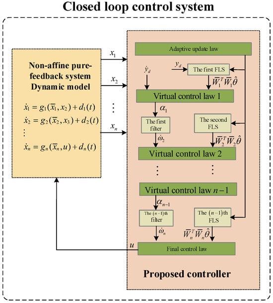
Figure 1.
A schematic diagram of the closed-loop control system.
Remark 3.
To enhance computational efficiency, the time-varying gain function is substituted with a constant parameter ψ. This modification eliminates the need to solve complex nonlinear equations associated with the control input u, thereby substantially accelerating the algorithm’s execution speed.
Theorem 1.
Assuming that the non-affine pure-feedback system (1) satisfies Assumptions 1–3, the proposed adaptive dynamic surface control system (it consists of three parts: intermediate control signals (12) and (13), the final control law (14), and the parameter adaptation mechanism (15)) can guarantee that all system states are semi-globally uniformly ultimately bounded (SGUUB), with the tracking errors approach asymptotically to an arbitrarily small neighborhood of zero.
Notice that the procedure of proof can be divided into n steps.
Step 1: Following the coordinate transformations established in (10), the error dynamics can be expressed as
where represents the output tracking error and denotes the filter error. The temporal derivative of the tracking error is obtained as
The definition of can be obtained from (10):
By adding and at both ends of the Equation (18), the state can be obtained:
Considering the strict-feedback structure in (3) and the new form of in (19), the derivative is formulated as
Substitution of (20) into (17) yields the error dynamics:
To ensure rapid convergence of the first subsystem, the virtual control law (12) is introduced. Its incorporation into (21) results in
Determining how to construct a suitable Lyapunov function can refer to the following experience: On the one hand, in order to ensure the positive definiteness of the Lyapunov function, the square terms of the key variables can be constructed. In addition, the proposed controller must strictly control the convergence trend of tracking error and filtering error, so they can be considered as important components of the Lyapunov function. Therefore, consider the following quadratic Lyapunov function candidate:
whose time derivative is given by
After substituting (22) into (24), the derivative of Lyapunov can be further expressed in the following form:
Choose a continuous real-valued bounded function as the input function of the first FLS (8):
with . Substituting (26) into (25), one has
Based on Lemma 2, the FLS can be adopted to approximate the such that for any accuracy , satisfies the following equation:
where is error function with upper bound . Then, (27) can be rewritten as
According to Young’s inequality, we can obtain
where has been defined in (6). Substituting (30) into (29), one gains the following result:
The first command control signal goes through a first-order filter; both the output derivative and the are satisfied in the following equilibrium:
where is the filter positive constant and . One of the conditions of which the dynamic system can be controlled is that the control signal is bounded; so, assume that , where is positive constant.
Based on the definition of (12), we assume that there exists a bounded continues function such that
where can be simplified as . According to (16) and (32), the time derivative of is computed as
Based on the nature of the absolute value inequality, one has
Using the completion squares theorem, we have
Substituting (36) into (35), the following result holds:
Substituting (37) into (31) we can conclude that
Choose a smooth scalar function , and its time derivative can be obtained:
Substituting (39) into (40) produces
The input function of the kth FLS is defined as follows:
with . Based on Assumption 3, we derive that is unknown bounded, so is also an unknown bounded function. Substituting (42) into (41) results in
It can be inferred from Lemma 2 that the FLS can be viewed as an approximator to model the unknown function such that for any accuracy , satisfies the following equation:
where is error function with upper bound . According to the definition of (44), (43) can be further deformed as follows:
with the help of the Young’s inequality, we conclude that
Substituting (46) into (45), one obtains
The filter output with design constant is defined as follows:
According to the same analysis, whereby, from (34) to (38), we have
where denotes . Substituting (49) into (47), one obtains the following result:
Step n: The nth error surface is , and its time derivative can be described as
Based on system (3) and (51), can be represented as
Substituting (14) into (52), one obtains
According to the definition of , it can be inferred that the constant design parameter is less than the minimum value of , so the following inequality holds:
Establish a Lyapunov function candidate , and its own derivative can be derived as
where . It can be inferred from (6) that is a constant value whose derivative is 0; so, the following equation holds:
Substituting (54) into (56) produces
The input function of the nth FLS is constructed as
with . Based on Assumption 3, it can be derived that is an unknown bounded function. Substituting (58) into (57) results in
Approximation of unknown function requires the FLS with given accuracy ; therefore, satisfies
where is error function with upper bound . Substituting (60) into (59) yields
Based on Young’s inequality, we obtain
Substituting (62) into (61), one obtains
Now, define the overall Lyapunov function for nonlinear control system (1) as follows:
Differentiating V with respect to time holds:
By substituting (63), (50), and (38) into (65), it can be observed that satisfies
Substituting the update law defined in (15) into (66) yields
Letting , we have the following inequality:
Assuming that , one can gain the following inequality:
Remark 4.
The constant parameter of each filter must be determined under the condition that the aforementioned inequality is satisfied. When the bounds of and q cannot be precisely estimated, a sufficiently small near zero may be selected to meet the required conditions. However, excessively reducing this parameter can introduce unbounded terms in the system dynamics differential equation, resulting in divergent solutions. To avoid this issue, the filter constant should be adjusted to a larger value.
As , one obtains
By using Young’s inequality, the following inequality holds:
Substituting (71) into (70) yields:
By substituting (68), (69), and (72) into (68), one obtains
Letting
where φ, ς, , , are positive constants, and , so . Then, (73) can be simplified as
Inequality (75) satisfies all the conditions mentioned in Lemma 1, so we conclude that all signals in the system (1) are SGUUB [37]. The proof of Theorem 1 is completed. Furthermore, when time tends to infinity, based on (64), the following result can be obtained:
when the control system enters steady state, its tracking error satisfies the following inequality:
Based on (77), it implies that arbitrarily given tracking accuracy can be achieved by determining adequate control parameters.
Remark 5.
By employing the framework of DSC [28], this research tackles with the fuzzy adaptive control problem for a class of pure-feedback systems by using only one adaptive updating law. Therefore, the proposed scheme not only is the extension of previous research achievements for strict-feedback systems [20], but it also reduces the computational burden in comparison of [28,35].
4. Simulation Results
This section provides two simulation examples to illustrate the advantages of the control algorithm described. Simulation Example 1 involves the tracking control problem of a second-order non-affine memory feedback system. Simulation Example 2 mainly takes a flexible robot as the controlled object, and further analyzes the performance of the proposed control algorithm and PID control.
4.1. Simulation Example 1
A comparison research between the presented approach and the fuzzy dynamic control method with unknown system dynamics [31] is provided to demonstrate the advantages of tracking performances, based on the same dynamics system and FLS. The same dynamic system and fuzzy logic system (FLS) are utilized for fair comparison. In this section, a nonlinear pure-feedback system subject to external disturbances (, ) is considered: [32]:
where , , and the desired tracking trajectory is selected as . Based on the aforementioned practical system (78), the control signal and the updating law are designed in the following forms:
where , ; therefore, the number of input neurons of and are 3 and 5, respectively. Furthermore, and have the same center position vector , seven nodes, and Gaussian width value 2. The initial conditions and design parameters of this simulation are given as follows: , , , , , , , , , , , , . Then, we set the filter positive constant of the first-order filter.
Remark 6.
The recommended value of ψ can be calculated using the theoretical Formula (2). In addition, ψ is regarded as the negative gain coefficient of tracking error. The smaller the value of ψ, the more significant its amplification effect on tracking error. In order to improve the convergence speed, a smaller ψ can be selected while ensuring the stability of the closed-loop system. In addition, through parameter debugging, it can be found that the design parameter φ has the greatest impact on the estimated value . The recommended range for setting the parameter φ is 0.5–20. The larger the value of φ, the faster the convergence speed of the estimated value . However, too fast a convergence speed can easily lead to estimation values falling into local optima. Therefore, in order to ensure sufficient approximation accuracy, a smaller φ can be prioritized.
Based on the same FLSs and initial conditions of state variables (, ), to facilitate comparison research, we provide the initial control signal, final actual control signal, and adaptive law of existing fuzzy control scheme (see [31]):
where , , , , , , , , , , , .
Remark 7.
It should be pointed out that two adaptive parameters ( and ) are required to update the weight vectors of all FLSs in the existing fuzzy control approach. However, the proposed control scheme needs only one adaptive parameter to achieve the above functions regardless of the system order; thus, for an n-order pure-feedback system, the online learning time of the FLSs of the proposed scheme can be reduced by , compared with the literature [31].
However, is used to approximate unknown function , where is the input vector of the first FLS. is utilized to approximate unknown function , which can be described as
where . In addition to state errors and disturbance terms, , also contain system functions (, ) and the derivative term of such that the degree of nonlinearity of and are significantly higher than and , respectively. As we are using FLSs with the same approximation ability in this simulation, the tracking performance of the existing control proposal [31] will be affected.
Figure 2, Figure 3, Figure 4, Figure 5 and Figure 6 show that the developed control method not only guarantees that tracking errors converge to an arbitrarily small region of zero, but it also ensures that state variables, control signal, and adaptive updating function are bounded, which proves the correctness of Theorem 1. Figure 2 displays the following performance of the presented controller. It is obviously observed that the output of the proposed controller is more closely tracking the . The range of variation between the maximum and minimum values of the steady-state tracking error (RTE) is regarded as a quantitative index for evaluating tracking performance.
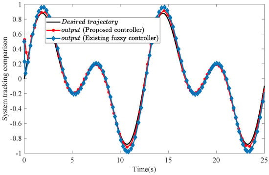
Figure 2.
System tracking comparison of the proposed controller (red dotted solid line) with existing control method (solid line marked with diamond shape).
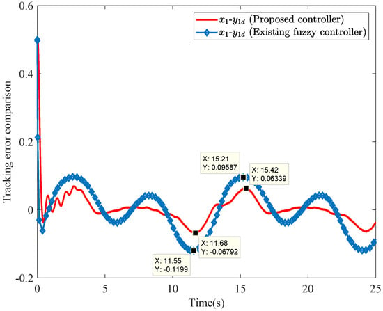
Figure 3.
Comparison of the tracking error of this paper (red solid line) with existing control method (solid line marked with diamond shape).
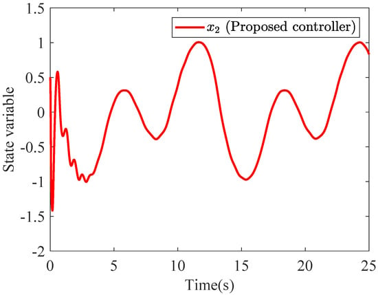
Figure 4.
State variable of the presented control scheme.
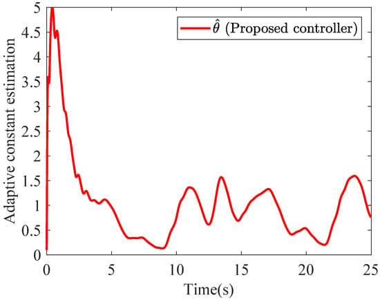
Figure 5.
Adaptive constant estimation of the presented control scheme.
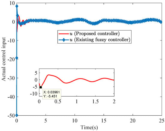
Figure 6.
Comparison of the actual control input u of this paper (red solid line) with the existing control method (solid line marked with diamond shape).
Remark 8.
A significant performance improvement is observed when comparing these two control strategies. The developed control scheme exhibits superior tracking accuracy over the conventional existing fuzzy control approach. Figure 3 demonstrates the relative tracking errors for the proposed and existing fuzzy controller. The maximum and minimum tracking errors of the proposed controller are 0.06339 and −0.06792, respectively, so its corresponding RTE index is calculated as 0.06339 + 0.06792 = 0.131. Similarly, the RTE index of the existing fuzzy controller is calculated as 0.09857 + 0.1199 = 0.2185. By contrast, the proposed controller achieves a 39.91% reduction in RTE, calculated as . This enhancement confirms the effectiveness of the new control strategy.
Figure 5 depicts the estimation of the adaptive constant parameter . The final control signals are depicted in Figure 6. The state trajectory is plotted in Figure 4. At the beginning of the control process, the conventional controller generates a negative control signal with an amplitude exceeding 50. In contrast, the developed controller produces a significantly reduced signal amplitude of −5.451. As a result, the overshoot is effectively suppressed. This improvement contributes to enhanced actuator durability.
4.2. Simulation Example 2
To further demonstrate the practicality of the control algorithm, it is specifically used to control the trajectory of a type of flexible robot:
If the link position , the link velocity , the rotor position , and the rotor velocity , then the dynamic Equation (86) of the flexible robot can be transformed into a standard form:
where , and ; , and represent some periodic time-varying disturbances. Due to (87) being a fourth-order system, it is necessary to design three virtual control laws, one actual control signal, and one adaptive law:
This flexible robot starts operating from the following initial state: , , , , , . The key control parameters are set to , , , , , , , , , , , , and , respectively. In addition, the node width parameter in the fuzzy logic system is set to 1.5, and the center position vector is set to . A classic PID controller is also used to control the joint angular displacement of the flexible robot [38]. The three key parameters of this PID controller, namely, proportional, integral, and derivative parameters, are set to 4, 0.5, and 0.1, respectively. The relevant simulation results are shown in Figure 7. The proposed control algorithm can ensure that the variation range of tracking error is reduced within the range of −0.0204 to 0.007171. However, the range of variation for the PID control algorithm extends to −0.0204 to 0.02022. Therefore, the control algorithm has a small tracking error.
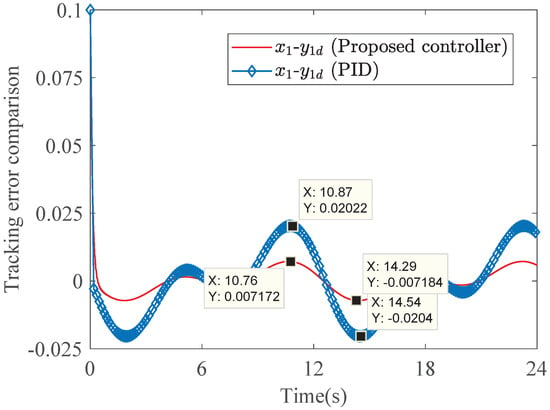
Figure 7.
Comparison of the tracking error of the proposed controller (red solid line) with the PID controller (solid line marked with diamond shape).
5. Conclusions
In this paper, a fuzzy adaptive dynamic surface control with constant gain was developed to tackle the tracking problem for non-affine pure-feedback systems with uncertain external disturbances. The abovementioned technique overcomes the “explosion of complexity” problem inherent in the backstepping design process. The difficulty of non-affine appearance in pure-feedback systems is eliminated by the mean-value theorem. The simulation results show that all in the closed-loop system signals are SGUUB, and the tracking error may be ensured to be arbitrarily small by tuning the parameters of control laws. Compared with existing fuzzy control algorithms, the RTE index of the proposed control algorithm is reduced by 39.91%. In addition, in the tracking control problem of a flexible robot, the presented control algorithm has also demonstrated excellent tracking performance, with tracking errors reduced to the range of −0.0204 to 0.007171. Future research will introduce a filter error compensation mechanism to further improve the tracking performance of the proposed algorithm.
Author Contributions
Conceptualization, L.C. and Y.W.; methodology, L.C., Y.W. and D.W.; formal analysis, L.C., Y.W. and J.C.; investigation, L.C., S.L. and D.W.; writing—original draft preparation, L.C.; writing—review and editing, L.C. and Y.W.; project administration, S.L.; funding acquisition, J.C. All authors have read and agreed to the published version of the manuscript.
Funding
This research was funded by National Key Research and Development Program (grant number 2023YFF0611203), and the National Natural Science Foundation of China (grant number 62203041). The APC was funded by 2023YFF0611203.
Institutional Review Board Statement
Not applicable.
Informed Consent Statement
Not applicable.
Data Availability Statement
Data is contained within the article.
Conflicts of Interest
Author Daiyue Wang was employed by the Beijing Xinqiao Technology Development Co., Ltd., China. The remaining authors declare that the research was conducted in the absence of any commercial or financial relationships that could be construed as a potential conflict of interest.
References
- Yi, Y.; Chen, D. Disturbance observer-based backstepping sliding mode fault-tolerant control for the hydro-turbine governing system with dead-zone input. ISA Trans. 2019, 88, 127–141. [Google Scholar] [CrossRef] [PubMed]
- Peng, Z.H.; Jiang, Y.; Wang, J. Event-triggered dynamic surface control of an underactuated autonomous surface vehicle for target enclosing. IEEE Trans. Ind. Electron. 2020, 68, 3402–3412. [Google Scholar] [CrossRef]
- Hu, Y.; Yan, H.; Zhang, H.; Wang, M.; Zeng, L. Robust adaptive fixed-time sliding-mode control for uncertain robotic systems with input saturation. IEEE Trans. Cybern. 2022, 53, 2636–2646. [Google Scholar] [CrossRef] [PubMed]
- Liu, K.; Wang, R.J.; Zheng, S.J.; Dong, S.F.; Sun, G.W. Fixed-time disturbance observer-based robust fault-tolerant tracking control for uncertain quadrotor UAV subject to input delay. Nonlinear Dyn. 2022, 107, 2363–2390. [Google Scholar] [CrossRef]
- Zhang, J.X.; Chai, T.Y. Singularity-free continuous adaptive control of uncertain underactuated surface vessels with prescribed performance. IEEE Trans. Syst. Man Cybern. Syst. 2021, 52, 5646–5655. [Google Scholar] [CrossRef]
- Yang, X.W.; Ge, Y.W.; Deng, W.X.; Yao, J.Y. Adaptive dynamic surface tracking control for uncertain full-state constrained nonlinear systems with disturbance compensation. J. Franklin Inst. 2022, 359, 2424–2444. [Google Scholar] [CrossRef]
- Guo, G.X.; Tan, H.R.; Feng, Y.; Wang, Y.N. Event-triggered fixed-time tracking control for uncertain networked autonomous surface vehicle with disturbances. Ocean Eng. 2024, 312, 100–119. [Google Scholar] [CrossRef]
- Sari, N.N.; Jahanshahi, H.; Fakoor, M. Adaptive Fuzzy PID Control Strategy for Spacecraft Attitude Control. Int. J. Fuzzy Syst. 2019, 21, 769–781. [Google Scholar] [CrossRef]
- Zhang, J.; Li, S.; Ahn, C.K.; Xiang, Z.R. Adaptive fuzzy decentralized dynamic surface control for switched large-scale nonlinear systems with full-state constraints. IEEE Trans. Cybern. 2021, 52, 10761–10772. [Google Scholar] [CrossRef]
- Lv, Z.X.; Ma, Y.M.; Liu, J.P.; Yu, J.P. Full-state constrained adaptive fuzzy finite-time dynamic surface control for PMSM drive systems. Int. J. Fuzzy Syst. 2021, 23, 804–815. [Google Scholar] [CrossRef]
- Wu, W.; Tong, S.C. Fixed-Time Adaptive Fuzzy Containment Dynamic Surface Control for Nonlinear Multiagent Systems. IEEE Trans. Fuzzy Syst. 2022, 30, 5237–5248. [Google Scholar] [CrossRef]
- Xie, S.Z.; Chen, Q.; Yang, Q.M. Adaptive fuzzy predefined-time dynamic surface control for attitude tracking of spacecraft with state constraints. IEEE Trans. Fuzzy Syst. 2022, 31, 2292–2304. [Google Scholar] [CrossRef]
- Ma, H.X.; Ren, R.N.; Tao, F.Z.; Fu, Z.M.; Wang, N. FTDO-based adaptive fuzzy fixed-time tracking control for uncertain unmanned helicopter with output constraints. Aerosp. Sci. Technol. 2024, 147, 109–116. [Google Scholar] [CrossRef]
- Long, L.J.; Si, T. Small-Gain Technique-Based Adaptive NN Control for Switched Pure-Feedback Nonlinear Systems. IEEE Trans. Cybern. 2019, 49, 1873–1884. [Google Scholar] [CrossRef] [PubMed]
- Xia, M.Z.; Zhang, T.P. Adaptive neural dynamic surface control for full state constrained stochastic nonlinear systems with unmodeled dynamics. J. Franklin Inst. 2019, 356, 129–146. [Google Scholar] [CrossRef]
- Na, J.; Ren, X.M.; Zheng, D.D. Adaptive Control for Nonlinear Pure-Feedback Systems With High-Order Sliding Mode Observer. IEEE Trans. Neural. Netw. Learn. Syst. 2013, 24, 370–382. [Google Scholar]
- Zuo, R.W.; Lv, M.L.; Li, Y.H.; Nie, H.Y. Neural-network-based adaptive tracking control for nonlinear pure-feedback systems subject to periodic disturbance. Int. J. Control 2022, 95, 2554–2564. [Google Scholar] [CrossRef]
- Zhu, Q.Q.; Niu, B.; Zhang, G.J.; Li, S.T.; Duan, P.Y. Adaptive fixed-time tracking control for a class of nonlinear pure-feedback systems: A relative threshold event-triggered strategy. ISA Trans. 2022, 122, 346–356. [Google Scholar] [CrossRef] [PubMed]
- Zhu, J.Y.; Li, S.R. Adaptive output dynamic feedback control for nonaffine pure-feedback time delay system with unknown backlash-like hysteresis. J. Franklin Inst. 2024, 361, 106–113. [Google Scholar] [CrossRef]
- Ling, S.; Wang, H.; Liu, P.X. Adaptive Fuzzy Dynamic Surface Control of Flexible-Joint Robot Systems with Input Saturation. IEEE/CAA J. Autom. Sin. 2019, 6, 97–106. [Google Scholar] [CrossRef]
- Liu, G.L.; Pan, Y.N.; Lam, H.K.; Liang, H.J. Event-triggered fuzzy adaptive quantized control for nonlinear multi-agent systems in nonaffine pure-feedback form. Fuzzy. Sets Syst. 2021, 416, 27–46. [Google Scholar] [CrossRef]
- Jia, F.J. Non-overshooting control of nonlinear pure-feedback systems. Syst. Control Lett. 2024, 185, 105–113. [Google Scholar] [CrossRef]
- Dai, Y.F.; Wang, Y.J.; Wang, C. Finite-time tracking control for time-delayed pure-feedback systems with guaranteed performance. Int. J. Robust Nonlinear Control 2024, 34, 3011–3032. [Google Scholar] [CrossRef]
- Lv, J.X.; Wang, C.H.; Liu, B.; Kao, Y.G.; Jiang, Y.S. Predefined-time output-feedback leader-following consensus of pure-feedback multiagent systems. IEEE Trans. Cybern. 2024, 54, 7754–7766. [Google Scholar] [CrossRef]
- Qi, J.; Zhang, J.; Krstic, M. Neural operators for PDE backstepping control of first-order hyperbolic PIDE with recycle and delay. Syst. Control Lett. 2024, 185, 105–114. [Google Scholar] [CrossRef]
- Chang, Y.; Feng, Z.G.; Zhang, X. Backstepping-based adaptive fuzzy tracking control for pure-feedback nonlinear multi-agent systems. Int. J. Syst. Sci. 2024, 55, 1584–1595. [Google Scholar] [CrossRef]
- He, K.H.; Dong, C.Y.; Wang, Q. Anti-disturbance dynamic inversion backstepping control for uncertain pure-feedback systems via multiple extended state observers. J. Frankl. Inst. 2021, 358, 6385–6407. [Google Scholar] [CrossRef]
- Zhang, T.P.; Ge, S.S. Adaptive dynamic surface control of nonlinear systems with unknown dead zone in pure feedback form. Automatica 2008, 44, 1895–1903. [Google Scholar] [CrossRef]
- Zhang, T.P.; Xu, H.X. Adaptive optimal dynamic surface control of strict-feedback nonlinear systems with output constraints. Int. J. Robust Nonlinear Control 2020, 30, 2059–2078. [Google Scholar] [CrossRef]
- Dun, A.; Wang, R.; Lei, F.; Yang, Y.N. Dynamic surface control for formation control of quadrotors with input constraints and disturbances. Trans. Inst. Meas. Control 2022, 44, 2500–2510. [Google Scholar] [CrossRef]
- Cheng, C.; Shen, H.K. Fractional-order dynamics and adaptive dynamic surface control of flexible-joint robots. Asian J. Control 2023, 25, 3029–3044. [Google Scholar] [CrossRef]
- Liu, M.R.; Zhang, W.H. Disturbance observer-based adaptive fuzzy control for pure-feedback systems with deferred output constraints. Nonlinear Dyn. 2025, 113, 1401–1418. [Google Scholar] [CrossRef]
- Wang, D. Neural network-based adaptive dynamic surface control of uncertain nonlinear pure-feedback systems. Int. J. Robust Nonlinear Control. 2011, 21, 527–541. [Google Scholar] [CrossRef]
- Wang, Q.; Cao, J.D.; Liu, H. Adaptive fuzzy control of nonlinear systems with predefined time and accuracy. IEEE Trans. Fuzzy Syst. 2022, 30, 5152–5165. [Google Scholar] [CrossRef]
- Bao, J.L.; Wang, H.Q.; Liu, X.P. Fuzzy Finite-Time Tracking Control for a Class of Nonaffine Nonlinear Systems with Unknown Dead Zones. IEEE Trans. Syst. Man Cybern Syst. 2021, 51, 452–463. [Google Scholar] [CrossRef]
- Yu, Z.X.; Yu, Z.S. Adaptive Neural Dynamic Surface Control For Nonlinear Pure-Feedback Systems with Multiple Time-Varying Delays: A Lyapunov-Razumikhin Method. Asian J. Control 2013, 15, 1124–1138. [Google Scholar] [CrossRef]
- Tong, S.C.; Li, Y.M. Adaptive fuzzy output feedback backstepping control of pure-feedback nonlinear systems via dynamic surface control technique. Int. J. Adapt. Control Signal Process. 2013, 27, 541–561. [Google Scholar] [CrossRef]
- Pan, Y.P.; Li, X.A.; Yu, H.Y. Efficient PID tracking control of robotic manipulators driven by compliant actuators. IEEE Trans. Control Syst. Technol. 2018, 27, 915–922. [Google Scholar] [CrossRef]
Disclaimer/Publisher’s Note: The statements, opinions and data contained in all publications are solely those of the individual author(s) and contributor(s) and not of MDPI and/or the editor(s). MDPI and/or the editor(s) disclaim responsibility for any injury to people or property resulting from any ideas, methods, instructions or products referred to in the content. |
© 2025 by the authors. Licensee MDPI, Basel, Switzerland. This article is an open access article distributed under the terms and conditions of the Creative Commons Attribution (CC BY) license (https://creativecommons.org/licenses/by/4.0/).