


Impedance-Based Inter-Turn Fault Diagnosis in Integrated Induction Motor and Drive Systems Using Space Voltage Vectors

Abstract
1. Introduction
- (1)
- To diagnose the ITF, the impedance of electrical machine is analyzed for the terminal connection. The terminal connection is implemented electrically through the space vector control of the three-phase inverter, eliminating the need for inverter disconnection or access to terminal connections when the ITF of the electrical machine is diagnosed.
- (2)
- The proposed method does not require the tracking of time-varying operational parameters, thereby simplifying implementation compared to online diagnostic approaches. Furthermore, a low-complexity algorithm based on phase impedance comparison across six space voltage vectors is employed, enhancing compatibility with embedded systems and real-time control platforms.
- (3)
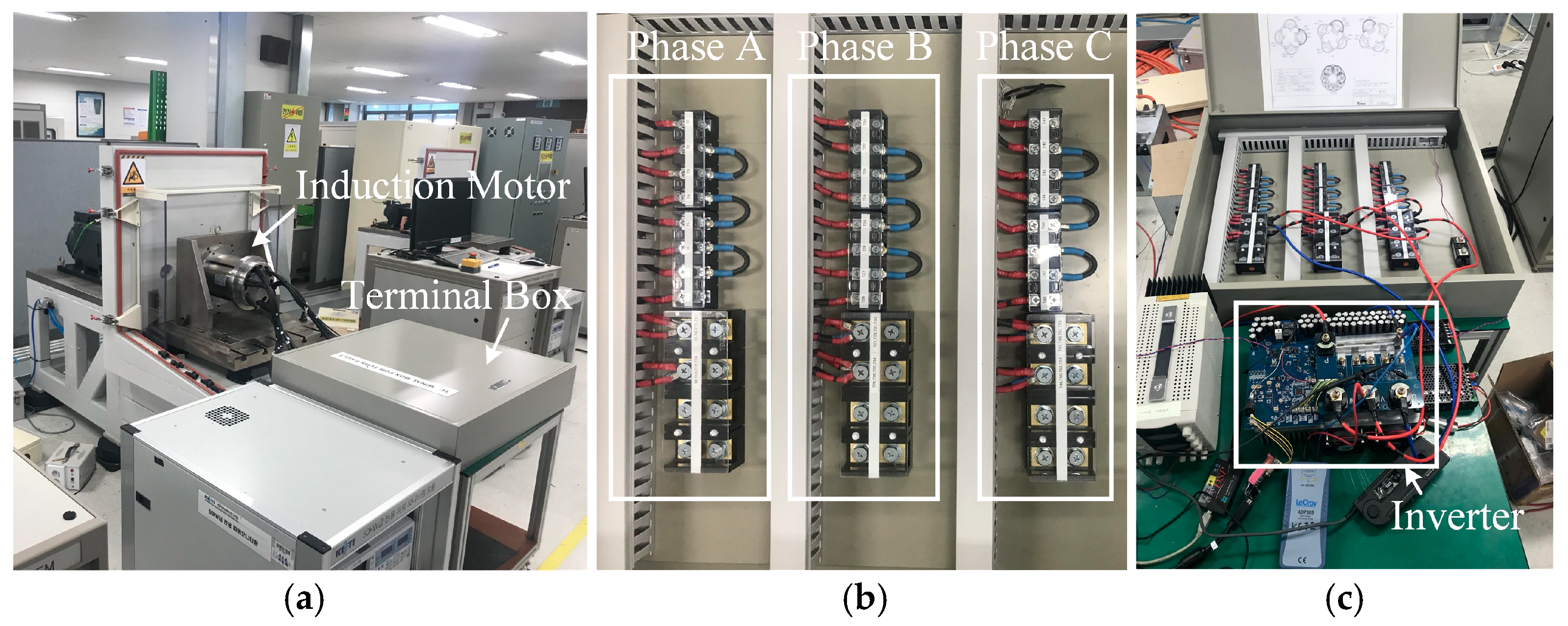
- A 12 kW three-phase IM was manufactured, and an experimental environment was implemented to verify the proposed algorithm for ITF diagnosis. The proposed ITF diagnosis algorithm was verified through the measurement of impedance for the space voltage vector for Y and Δ connections.
2. Impedance Analysis of Inter-Turn Fault of Induction Motor
2.1. Mathematical Model of Induction Motor with Inter-Turn Fault
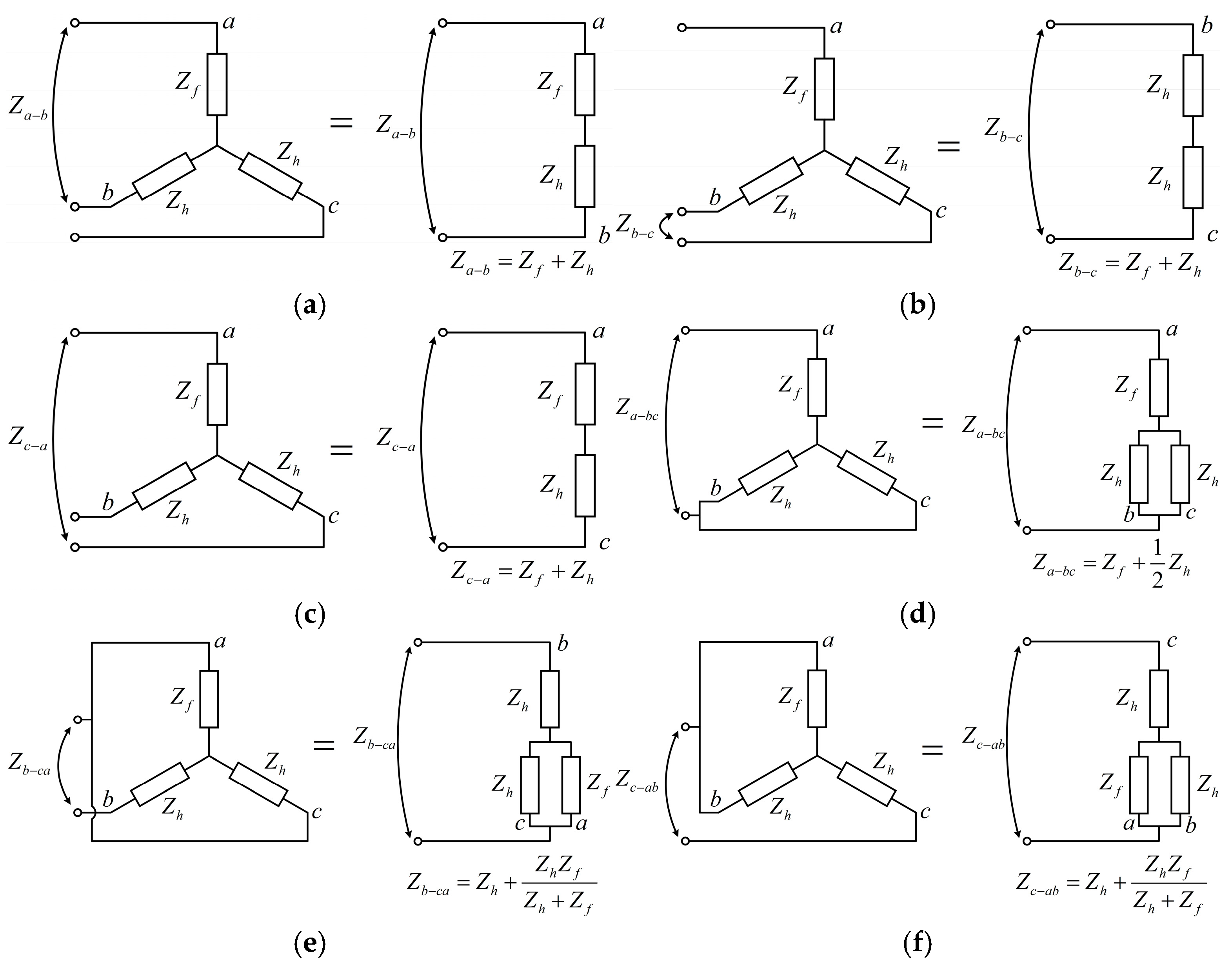
2.2. Impedance Analysis with Y Connection
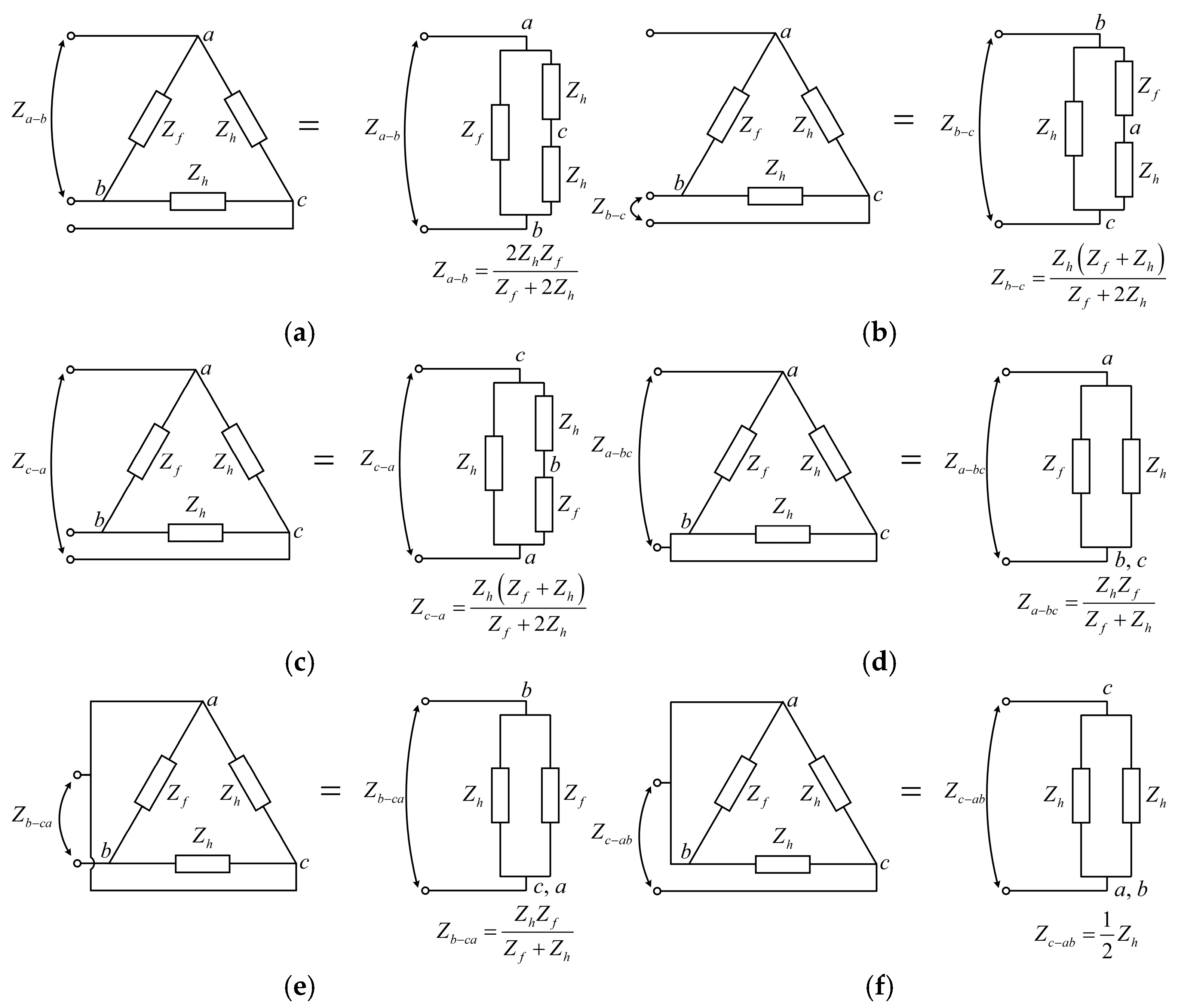
2.3. Impedance Analysis with Δ Connection
3. Inter-Turn Fault Diagnosis of Integrated Motor and Drive Systems
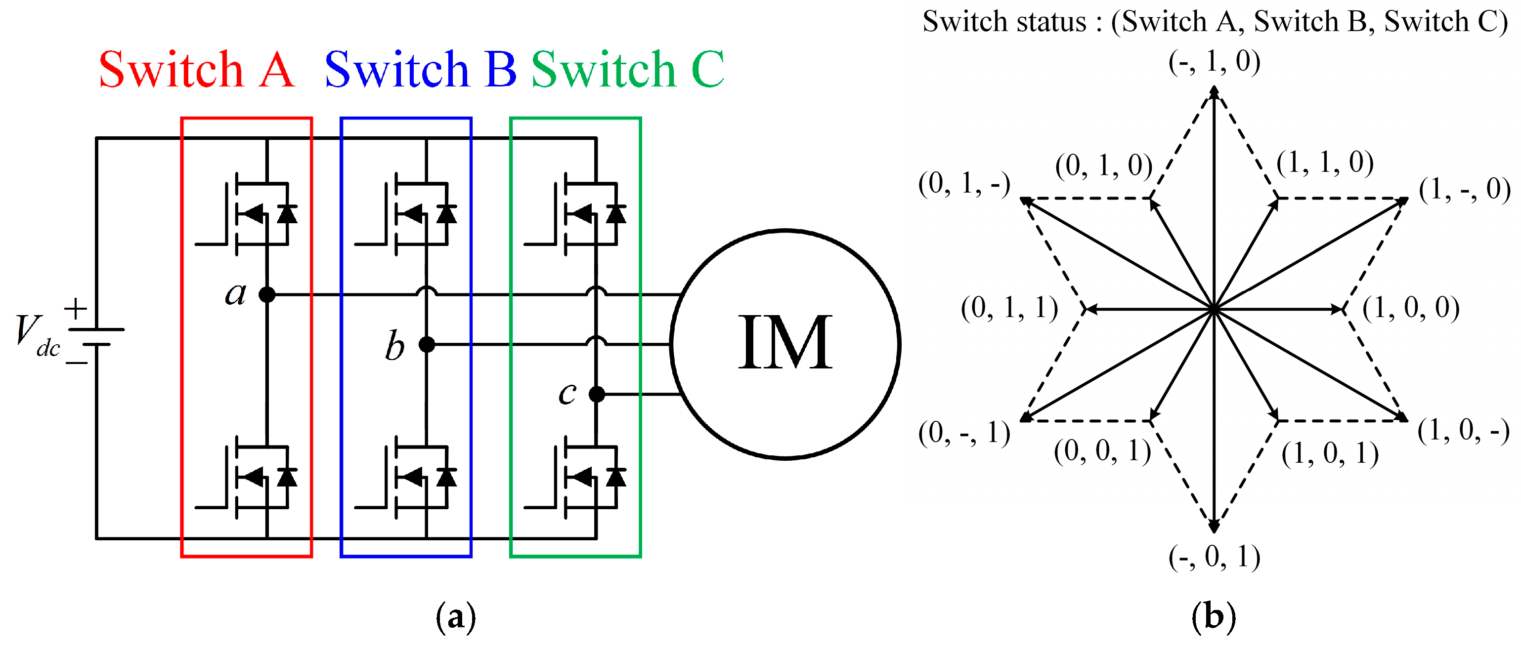
3.1. Space Voltage Vector in Three-Phase Inverter
3.2. Terminal Connection for Space Voltage Vector
3.3. Fault Diagnosis Algorithm
4. Experimental Verification
5. Conclusions
Author Contributions
Funding
Institutional Review Board Statement
Informed Consent Statement
Data Availability Statement
Conflicts of Interest
References
- Azab, M. A Review of Recent Trends in High-Efficiency Induction Motor Drives. Vehicles 2025, 7, 15. [Google Scholar] [CrossRef]
- Zhang, B.; Song, Z.; Liu, S.; Huang, R.; Liu, C. Overview of Integrated Electric Motor Drives: Opportunities and Challenges. Energies 2022, 15, 8299. [Google Scholar] [CrossRef]
- Wu, X.; Geng, Y.; Li, M.; Wang, W.; Tu, M. Inter-Turn Short Circuit Diagnosis of Permanent Magnet Synchronous Motor Based on Siamese Convolutional Neural Network Under Small Fault Samples. IEEE Sensors J. 2024, 24, 26982–26993. [Google Scholar] [CrossRef]
- Bahrami-Fard, M.; Chen, T.; Winchell, E.; Fahimi, B. Integrated Induction Motor Drive for Variable Speed Industrial Applications. IEEE Trans. Power Electron. 2025, 40, 7176–7188. [Google Scholar] [CrossRef]
- Gulsuna, O.; Tokgoz, F.; Karakaya, F.; Keysan, O. Design and Analysis of a GaN-Based Megahertz Integrated Motor Drive for a PCB Motor. IEEE Trans. Ind. Electron. 2024, 71, 15435–15444. [Google Scholar] [CrossRef]
- Zhang, J.; Zhang, X.; Gu, C.; Li, J.; Zhang, H.; Zhao, H. Characterizations of PM Synchronous Motor with an Integrated Common-Mode Voltage Filter. IEEE Trans. Ind. Appl. 2024, 60, 353–366. [Google Scholar]
- Nam, D.W.; Hong, M.K.; Jo, N.R.; Jung, D.H.; Kim, W.H. Design of Coil Patterns for an Axial Flux Permanent Magnet Synchronous Motor with PCB Stator. IEEE Access 2025, 13, 12936–12944. [Google Scholar] [CrossRef]
- Naradhipa, A.M.; Kim, S.; Yang, D.; Choi, S.; Yeo, I.; Lee, Y. Power Density Optimization of 700 kHz GaN-Based Auxiliary Power Module for Electric Vehicles. IEEE Trans. Power Electron. 2021, 36, 5610–5621. [Google Scholar] [CrossRef]
- Hwang, K.Y.; Kim, S.I.; Song, B.K. Single Winding Type Determination of Dual Winding Three-Phase Motor Considering Overheat Problem in Integrated Electric Braking System of Autonomous Vehicles. IEEE Trans. Transp. Electrific. 2023, 9, 656–666. [Google Scholar] [CrossRef]
- Sun, X.; Song, C.; Zhang, Y.; Sha, X.; Diao, N. An Open-Circuit Fault Diagnosis Algorithm Based on Signal Normalization Preprocessing for Motor Drive Inverter. IEEE Trans. Instrum. Meas. 2023, 72, 3513712. [Google Scholar] [CrossRef]
- Orlowska-Kowalska, T.; Wolkiewicz, M.; Pietrzak, P.; Skowron, M.; Ewert, P.; Tarchala, G.; Krzysztofiak, M.; Kowalski, C.T. Fault Diagnosis and Fault-Tolerant Control of PMSM Drives–State of the Art and Future Challenges. IEEE Access 2022, 10, 59979–60024. [Google Scholar] [CrossRef]
- Gupta, V.; Sultana, M.; Khanna, A. Hybrid optimization-based approach for transmission line parameter identification in the presence of noise. Data Anal. J. 2023, 9, 100182. [Google Scholar]
- Jin, L.; Wang, X.; Mao, Y.; Lu, L.; Wang, Z. Online Attribute Matching Based Few-Sample Data-Driven Diagnosis of Electrical Faults in PMSM Drive. IEEE Trans. Power Electron. 2024, 39, 2620–2631. [Google Scholar] [CrossRef]
- Tokgoz, F.; Gülsuna, Ö.; Karakaya, F.; Cakal, G.; Keysan, O. Mechanical and Thermal Design of an Optimized PCB Motor for an Integrated Motor Drive System with GaNFETs. IEEE Trans. Energy Convers. 2023, 38, 653–661. [Google Scholar] [CrossRef]
- Wang, S.; Sun, Y.; Huang, Z.; Mu, S. Analysis of Stator Internal Phase-to-Phase Short Circuit in the 12-Phase Synchronous Generator with Rectifier-Load System. IEEE Trans. Energy Convers. 2018, 33, 299–311. [Google Scholar] [CrossRef]
- Yuan, W.; Li, Y.; Xu, L.; Li, T.; Chen, X. A Fast Faulty Phase Selection Method Considering Fault Tolerance for Single Phase to Ground Fault in Distribution Networks. IEEE Trans. Instrum. Meas. 2023, 72, 3533212. [Google Scholar] [CrossRef]
- Yuan, J.; Feng, C.; Ji, Y.; Liu, X.; Dong, X.; Liu, J. Faulty Feeder Detection for Successive Single Phase-to-Ground Faults Based on Line Model Recognition and Correlation Comparison. IEEE Trans. Power Del. 2025, 40, 750–763. [Google Scholar] [CrossRef]
- Gao, C.; Gao, B.; Xu, X.; Si, J.; Hu, Y. Automatic Demagnetization Fault Location of Direct-Drive Permanent Magnet Synchronous Motor Using Knowledge Graph. IEEE Trans. Instrum. Meas. 2024, 73, 3502312. [Google Scholar] [CrossRef]
- Bonet-Jara, J.; Pons-Llinares, J.; Gyftakis, K.N. Comprehensive Analysis of Principal Slot Harmonics as Reliable Indicators for Early Detection of Interturn Faults in Induction Motors of Deep-Well Submersible Pumps. IEEE Trans. Ind. Electron. 2023, 70, 11692–11702. [Google Scholar] [CrossRef]
- Choi, J.; Kim, S.H.; Lee, W.K.; Lee, J.S. Rapid Control Prototyping and Analysis of a Fault Diagnosis and Amplifying Algorithm for Broken Rotor Bar Induction Motor Drives. IEEE Access 2025, 13, 19064–19074. [Google Scholar] [CrossRef]
- Kang, Y.; Yao, L. Fault Diagnosis for Permanent Magnet Synchronous Motor with Demagnetization Fault and Sensor Fault. IEEE Trans. Instrum. Meas. 2024, 73, 3533311. [Google Scholar] [CrossRef]
- Ma, J.; Bai, X.; Ma, F.; Zhuo, S.; Sun, B.; Li, C. Convolutional Neural Network Design Based on Weak Magnetic Signals and Its Application in Aircraft Bearing Fault Diagnosis. IEEE Sens. J. 2024, 24, 36031–36043. [Google Scholar] [CrossRef]
- Niu, G.; Dong, X.; Chen, Y. Motor Fault Diagnostics Based on Current Signatures: A Review. IEEE Trans. Instrum. Meas. 2023, 72, 3520919. [Google Scholar] [CrossRef]
- Lang, W.; Hu, Y.; Gong, C.; Zhang, X.; Xu, H.; Deng, J. Artificial Intelligence-Based Technique for Fault Detection and Diagnosis of EV Motors: A Review. IEEE Trans. Transp. Electrific. 2022, 8, 384–406. [Google Scholar] [CrossRef]
- Chen, C.S.; Lin, C.J.; Yang, F.J.; Lin, F.C. Model Design of Inter-Turn Short Circuits in Internal Permanent Magnet Synchronous Motors and Application of Wavelet Transform for Fault Diagnosis. Appl. Sci. 2024, 14, 9570. [Google Scholar] [CrossRef]
- Qin, Y.; Li, G.J.; Jia, C.; McKeever, P. Investigation of Inter-Turn Short-Circuit Fault of PM Machines Using PWM Voltage-Based Modeling. IEEE Trans. Transp. Electrific. 2024, 10, 1324–1334. [Google Scholar] [CrossRef]
- Cui, R.; Fan, Y.; Li, C. On-Line Inter-Turn Short-Circuit Fault Diagnosis and Torque Ripple Minimization Control Strategy Based on OW Five-Phase BFTHE-IPM. IEEE Trans. Energy Convers. 2018, 33, 2200–2209. [Google Scholar] [CrossRef]
- Chen, Q.; Han, X.; Liu, G.; Zhao, W.; Shi, H. Inter-Turn Fault Diagnosis and Control for Five-Phase PMSMs by Disturbance Observer. IEEE Trans. Ind. Electron. 2024, 71, 13901–13909. [Google Scholar] [CrossRef]
- Dongare, U.V.; Umre, B.S.; Ballal, M.S.; Dongare, V.P. Online Inter-Turn Fault Detection in Wound Rotor Induction Motors Based on VI Loci Pattern. IEEE Trans. Ind. Appl. 2024, 60, 411–425. [Google Scholar] [CrossRef]
- Asad, B.; Vaimann, T.; Belahcen, A.; Kallaste, A.; Rassõlkin, A.; Ghafarokhi, P.S.; Kudelina, K. Transient Modeling and Recovery of Non-Stationary Fault Signature for Condition Monitoring of Induction Motors. Appl. Sci. 2021, 11, 2806. [Google Scholar] [CrossRef]
- Zhang, J.; Zhan, W.; Ehsani, M. Fault-Tolerant Control of PMSM with Inter-Turn Short-Circuit Fault. IEEE Trans. Energy Convers. 2019, 34, 2267–2275. [Google Scholar] [CrossRef]
- Asad, B.; Vaimann, T.; Belahcen, A.; Kallaste, A.; Rassõlkin, A.; Iqbal, M.N. The Cluster Computation-Based Hybrid FEM-Analytical Model of Induction Motor for Fault Diagnostics. Appl. Sci. 2020, 10, 7572. [Google Scholar] [CrossRef]
- Gu, B.-G. Offline Interturn Fault Diagnosis Method for Induction Motors by Impedance Analysis. IEEE Trans. Ind. Electron. 2018, 65, 5913–5920. [Google Scholar] [CrossRef]


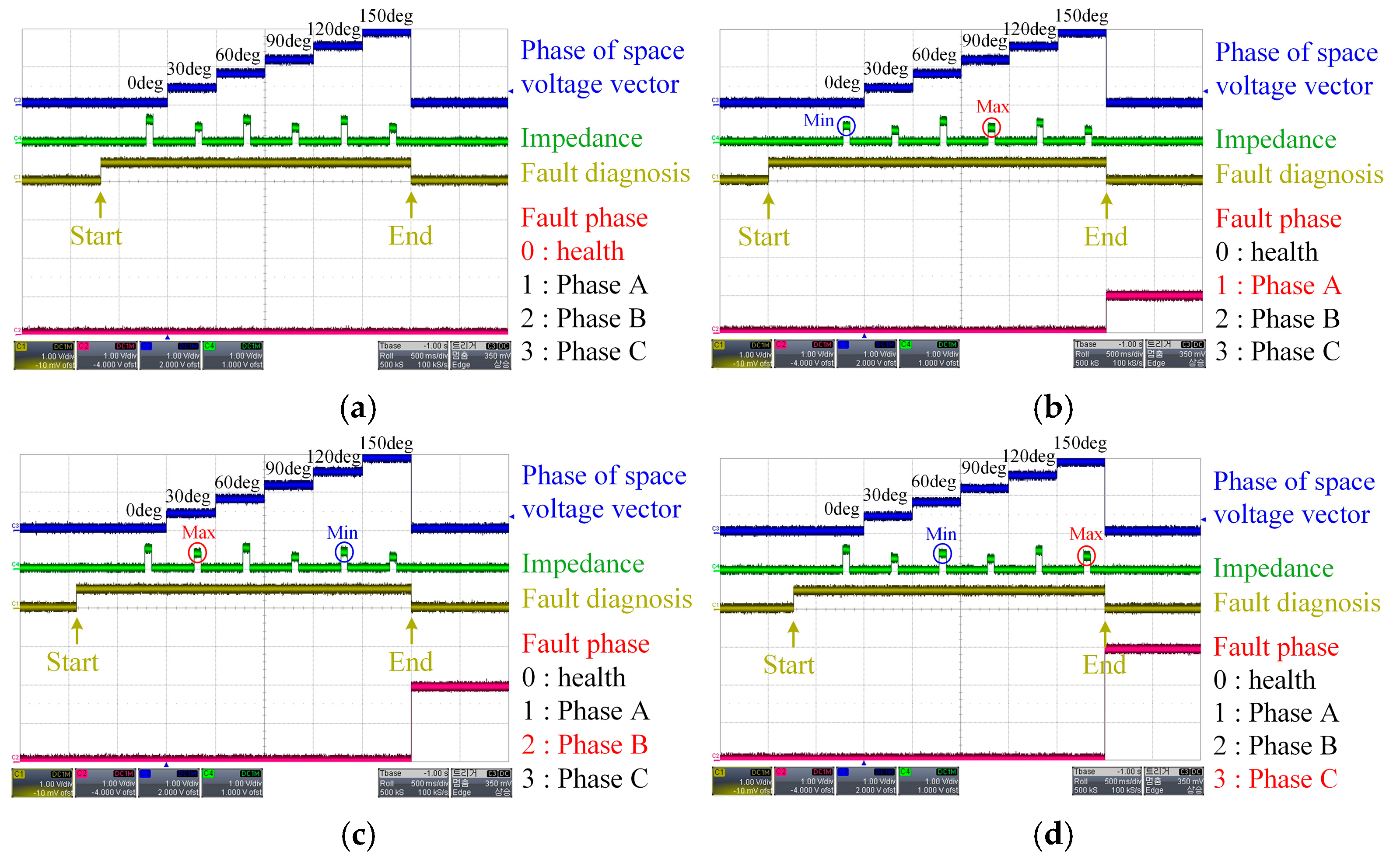
| Fault Phase | Maximum Impedance among Za-b, Zb-c, and Zc-a | Minimum Impedance among Za-bc, Zb-ca, and Zc-ab |
|---|---|---|
| A | Zb-c | Za-bc |
| B | Zc-a | Zb-ca |
| C | Za-b | Zc-ab |
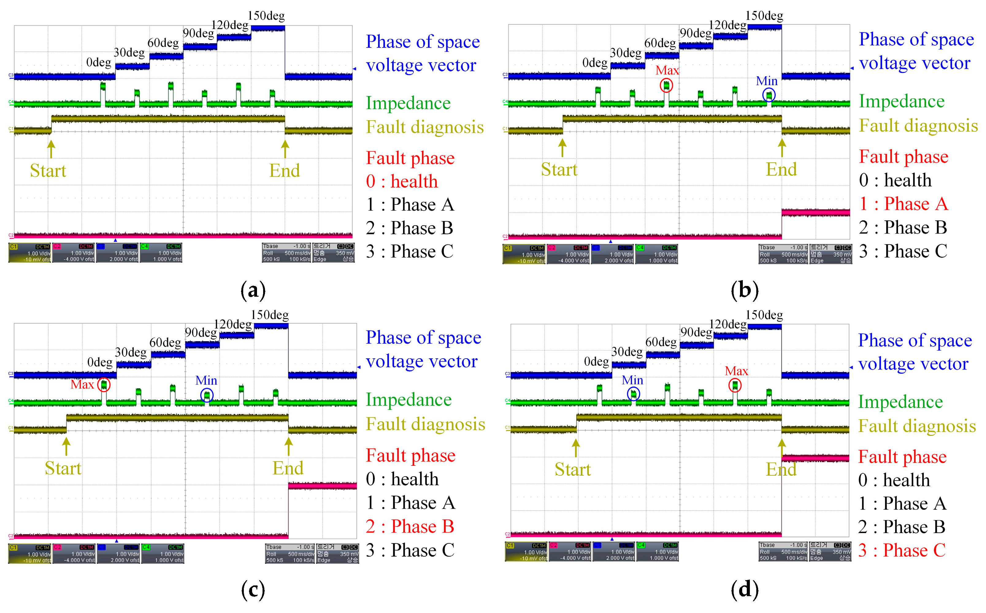
| Fault Phase | Minimum Impedance among Za-b, Zb-c, and Zc-a | Maximum Impedance among Za-bc, Zb-ca, and Zc-ab |
|---|---|---|
| A | Za-b | Zc-ab |
| B | Zb-c | Za-bc |
| C | Zc-a | Zb-ca |
| Phase A Switch | Phase B Switch | Phase C Switch | Phase of Voltage Vector [°] |
|---|---|---|---|
| 1 | 0 | 0 | 0 |
| 1 | - | 0 | 30 |
| 1 | 1 | 0 | 60 |
| - | 1 | 0 | 90 |
| 0 | 1 | 0 | 120 |
| 0 | 1 | - | 150 |
| 0 | 1 | 1 | 180 |
| 0 | - | 1 | 210 |
| 0 | 0 | 1 | 240 |
| - | 0 | 1 | 270 |
| 1 | 0 | 1 | 300 |
| 1 | 0 | - | 330 |
| Phase of Space Voltage Vector [°] | Terminal Connection |
|---|---|
| 0 and 180 | a-bc |
| 30 and 210 | c-a |
| 60 and 240 | c-ab |
| 90 and 270 | b-c |
| 120 and 300 | b-ca |
| 150 and 330 | a-b |
| Contents | Value | Unit |
|---|---|---|
| DC voltage | 52 | V |
| Power | 12 | kW |
| Current | 248 | Arms |
| Phase resistance | 11.5 | mΩ |
| Phase inductance | 0.6 | mH |
| Fault resistance | 3.6 | mΩ |
| Frequency of space voltage vector | 500 | Hz |
Disclaimer/Publisher’s Note: The statements, opinions and data contained in all publications are solely those of the individual author(s) and contributor(s) and not of MDPI and/or the editor(s). MDPI and/or the editor(s) disclaim responsibility for any injury to people or property resulting from any ideas, methods, instructions or products referred to in the content. |
© 2025 by the authors. Licensee MDPI, Basel, Switzerland. This article is an open access article distributed under the terms and conditions of the Creative Commons Attribution (CC BY) license (https://creativecommons.org/licenses/by/4.0/).
Share and Cite
Ahn, J.; Lee, J.; Kim, H. Impedance-Based Inter-Turn Fault Diagnosis in Integrated Induction Motor and Drive Systems Using Space Voltage Vectors. Appl. Sci. 2025, 15, 6065. https://doi.org/10.3390/app15116065
Ahn J, Lee J, Kim H. Impedance-Based Inter-Turn Fault Diagnosis in Integrated Induction Motor and Drive Systems Using Space Voltage Vectors. Applied Sciences. 2025; 15(11):6065. https://doi.org/10.3390/app15116065
Chicago/Turabian StyleAhn, Jungho, Ju Lee, and Hyunwoo Kim. 2025. "Impedance-Based Inter-Turn Fault Diagnosis in Integrated Induction Motor and Drive Systems Using Space Voltage Vectors" Applied Sciences 15, no. 11: 6065. https://doi.org/10.3390/app15116065
APA StyleAhn, J., Lee, J., & Kim, H. (2025). Impedance-Based Inter-Turn Fault Diagnosis in Integrated Induction Motor and Drive Systems Using Space Voltage Vectors. Applied Sciences, 15(11), 6065. https://doi.org/10.3390/app15116065