Article

A Tile-Based Multi-Core Hardware Architecture for Lossless Image Compression and Decompression

1
National Space Science Center, Chinese Academy of Sciences, Beijing 100190, China
2
School of Computer Science and Technology, University of Chinese Academy of Sciences, Beijing 100190, China
*
Author to whom correspondence should be addressed.
Appl. Sci. 2025, 15(11), 6017; https://doi.org/10.3390/app15116017
Submission received: 28 April 2025 / Revised: 24 May 2025 / Accepted: 26 May 2025 / Published: 27 May 2025

Abstract

:
Lossless image compression plays a vital role in improving data storage and transmission efficiency without compromising data integrity. However, the throughput of current lossless compression and decompression systems remains limited and is unable to meet the growing demands of high-speed data transfer. To address this challenge, a previously proposed hybrid lossless compression and decompression algorithm has been implemented on an FPGA platform. This implementation significantly improves processing speed and efficiency. A multi-core system architecture is introduced, utilizing the processing system (PS) and programmable logic (PL) of a Xilinx Zynq-706 evaluation board. The PS handles coordination. The PL performs compression and decompression using multiple cores. Each core can process up to eight image tiles at the same time. The compression process is designed with a four-stage pipeline, and decompression is managed by a dynamic state machine to ensure optimized control. The parallel architecture and innovative algorithm design enable high-throughput operation, achieving compression and decompression rates of 480 Msubpixels/s and 372 Msubpixels/s, respectively. Through this work, a practical and high-performance solution for real-time lossless image compression is demonstrated.

1. Introduction

Efficient image compression and decompression algorithms are considered essential for managing the increasing volume of image data across various domains, including multimedia [1,2], medical imaging [3,4], and surveillance systems [5,6,7]. These applications require high-throughput and low-latency solutions to support real-time performance and data transmission.
To meet these demands, hardware-accelerated lossless compression and decompression algorithms have become increasingly critical. Conventional techniques such as BPG [8], CALIC [9], and PNG [10], though effective in software environments, are often constrained in hardware due to their strong dependence on algorithmic parameters. This dependence makes the effective use of pipelining difficult, thereby limiting their scalability on hardware platforms.
Lightweight hybrid compression algorithms, such as JPEG-LS [11], have emerged as promising alternatives. Recognized for their compression efficiency and relatively low computational complexity, these methods have been widely adopted in FPGA implementations [12,13,14,15,16,17,18].
Earlier foundational research by Klimesh et al. [16] introduced modifications to the run-length coding mode in JPEG-LS, successfully reducing algorithmic complexity, though only modest gains in processing speed were realized. Merlino and Abramo [17] explored pipelining for JPEG-LS, but their design was limited to clock frequencies of approximately 21 MHz for the encoder and 16 MHz for the decoder.
Subsequent efforts focused on boosting throughput. Mert and Murat [18] demonstrated a fully pipelined JPEG-LS encoder capable of achieving 120 Mpixels/s, marking a substantial advance in real-time image compression capabilities.
To further improve the trade-off between performance and resource usage, Wang et al. [14] proposed a hardware/software co-design utilizing pixel-level parallelism and a pseudo-lossless compression approach. However, this method increased cache requirements and slightly reduced compression efficiency. Similarly, in the works of Ferretti et al. [15], pipeline implementations addressed data and structural hazards primarily through stalling, a limitation caused by the algorithm’s inherent dependence on sequential parameter updates.
More recently, Liu et al. [12] introduced an adaptive pipelined architecture that improves parameter update management, enhances context modeling, and supports block-level parallel processing. This design achieved an operating frequency of 108.6 MHz and a throughput of 43.03 Mpixels/s, offering a more balanced and efficient implementation suitable for FPGA-based platforms.
As a result, the throughput achieved by these systems is still insufficient to meet the demands of modern high-speed applications. To overcome these limitations, hybrid compression strategies more suitable for FPGA acceleration have been explored [19]. By leveraging the parallel processing capabilities of hardware, higher processing speeds can be achieved. In this study, a hybrid image compression and decompression algorithm is reviewed and optimized for hardware implementation. The algorithm integrates run-length coding [20], predictive coding [21], and a non-coding mechanism. These techniques are selectively applied based on the characteristics of the image data, enabling effective compression across various image types while maintaining lossless fidelity.
A tile-based strategy is adopted in the algorithm, where input images are divided into smaller regions for independent compression and decompression. This approach enables hardware support for multi-core operation, allowing multiple processing cores to handle image tiles in parallel. A multi-core system architecture is proposed, where up to eight tiles can be processed concurrently. The algorithm is designed with low dependency on specific parameters, making it well suited for pipelined acceleration. As a result, a four-stage pipeline is applied in the compression process. For decompression, a dynamic state machine is utilized to further enhance system performance.
The system has been tested on a Xilinx Zynq-706 evaluation board, Xilinx, Inc., San Jose, CA, USA. Experimental results show that a compression throughput of 480 Msubpixels/s and a decompression throughput of 372 Msubpixels/s are achieved. These results demonstrate that the proposed method outperforms conventional implementations in both speed and resource efficiency.
The proposed solution is particularly well suited for real-time applications in areas such as medical imaging, multimedia processing, and video surveillance. These fields require high-speed and lossless image handling capabilities, which are supported by the architecture presented in this work.
In summary, the main contributions of this research are as follows:
  • A novel high-throughput, lossless compression and decompression system is proposed, which employs a tile-based approach to enhance parallel processing capabilities. By distributing images across multiple compression and decompression cores within a specially developed multi-core architecture, the system significantly improves processing efficiency while building on previously introduced algorithms.
  • A four-stage pipeline is implemented for the compression algorithm to maximize clock frequency, further increasing throughput.
  • Dynamic state machines are utilized in the decompression algorithm, significantly improving throughput.
The remainder of this paper is organized as follows. Relevant studies are reviewed in Section 1. The proposed architecture is described in Section 2. In Section 3, the experimental results are presented and discussed. Finally, the conclusions of this paper are provided in Section 4.

2. Compression and Decompression Algorithms Based on Hybrid Strategies

An image compression and decompression algorithm based on hybrid strategies is proposed, combining multiple coding techniques to improve efficiency while maintaining lossless fidelity. Run-length coding, predictive coding, and non-coding strategies are integrated into the algorithm. Each method is selectively applied based on the local characteristics of the pixel data to optimize compression performance. The algorithm is designed on the premise that the image is divided into discrete tiles, which can be sized at 4 × 4, 8 × 8, or 16 × 16. An advantage of tile-based processing is that it is not affected by the overall image size. Regardless of the dimensions, the image is divided into smaller tiles, and compression and decompression are carried out as independent tasks for each tile. This approach standardizes the processing method for images of varying sizes while reducing overall computational complexity. It should be noted that the tile size cannot be changed within a single image. However, different tile sizes can be selected for different images.

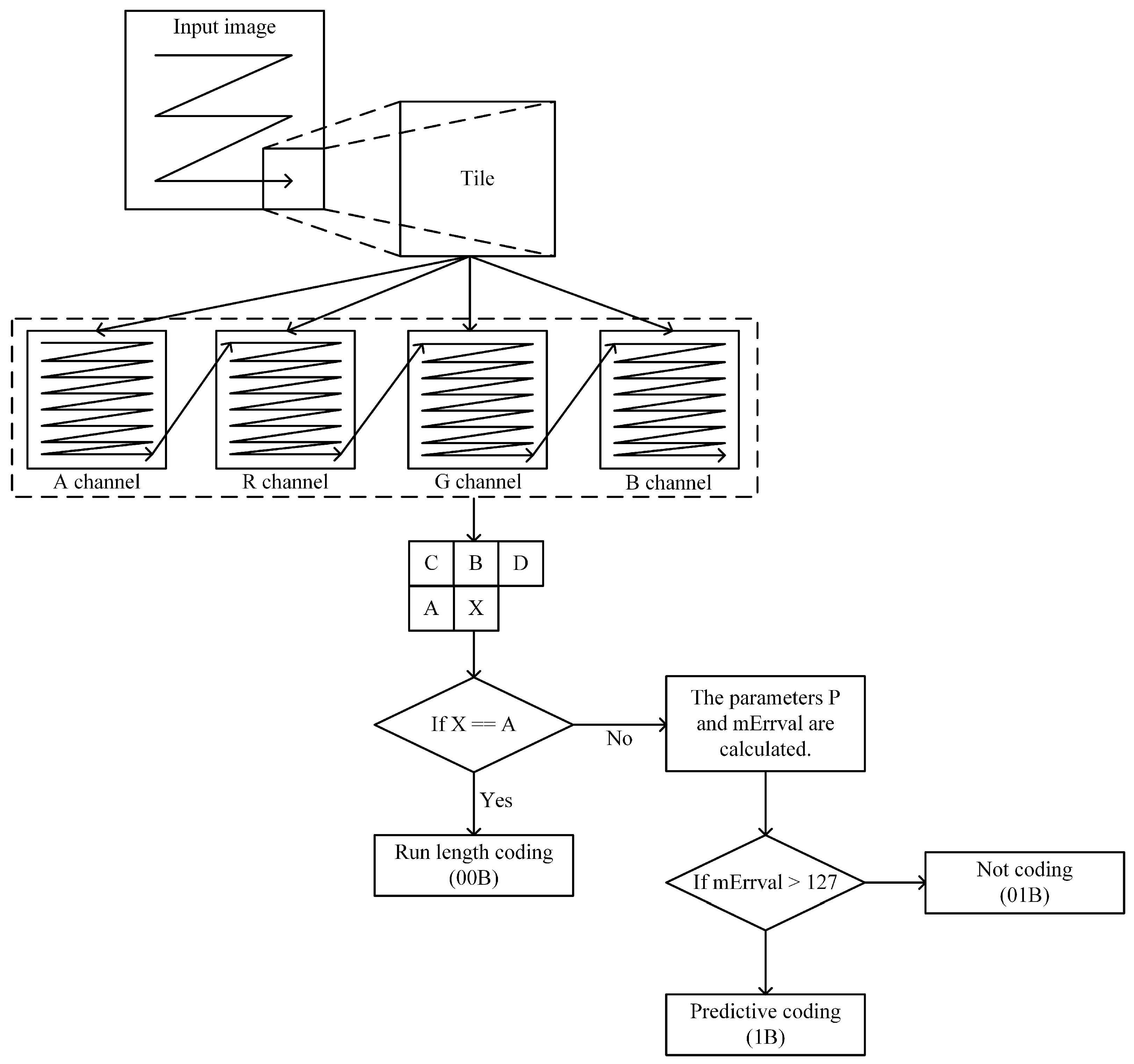
2.1. Compression Workflow

The compression workflow is illustrated in Figure 1. During the compression phase, the image is processed sequentially from left to right and top to bottom. Each tile is decomposed into its constituent pixel components: Alpha (transparency), red, green, and blue (ARGB), which correspond to the respective color channels. These components are read and compressed according to a predefined pattern, indicated by the directional arrows in Figure 1. The compression mechanism involves analyzing the current pixel component “x” in relation to its neighboring components: “A” (immediately preceding), “B” (directly above), “C” (upper left), and “D” (upper right). Each compression strategy is associated with a unique binary flag: ‘00B’ is assigned to run-length coding, ‘01B’ signifies non-coding, and ‘1B’ is reserved for predictive coding. To determine the appropriate compression strategy, the algorithm uses computational formulas, denoted as Equations (1) and (2), to calculate the parameters P and m E r r v a l . These parameters play a critical role in deciding whether predictive coding or non-coding should be applied. Once the compression mode is selected, the encoded pixel component “x” is output along with its corresponding flag bit, which indicates the encoding strategy, followed by the actual encoded data.

2.2. Decompression Workflow

In the case of decompression, the algorithm inversely applies the strategies to reconstruct the image data from the compressed state. The workflow, as depicted in Figure 2, ensures the restoration of the original image. During the decompression stage, the encoded data stream is meticulously parsed. This commences with the flag bit’s interpretation, which dictates the ensuing decompression mode. Subsequently, the data volume that corresponds to the decompression mode is read. The pixel component, once decompressed, is accurately placed back within its designated position in the tile. This precise repositioning is critical for the integrity of the image reconstruction process. Upon the conclusion of the pixel components’ decompression, the original image is meticulously reconstructed, reflecting the effectiveness of the algorithm in preserving the integrity of the image data. This complex process, governed by the flag bits and detailed computational methods, ensures the precision of the decompression, enabling the complete restoration of the image to its pristine condition. By harnessing the power of these three coding strategies within a block-based compression framework, the algorithm effectively reduces data redundancy, achieving substantial compression ratios without compromising on the quality of the decompressed images. This methodical approach enhances the efficiency of image compression and decompression, making it suitable for applications where storage or bandwidth conservation is critical.

2.3. Strategies

The operational details of the three strategies are described in the following sections, including how each is applied during the compression and decompression processes.

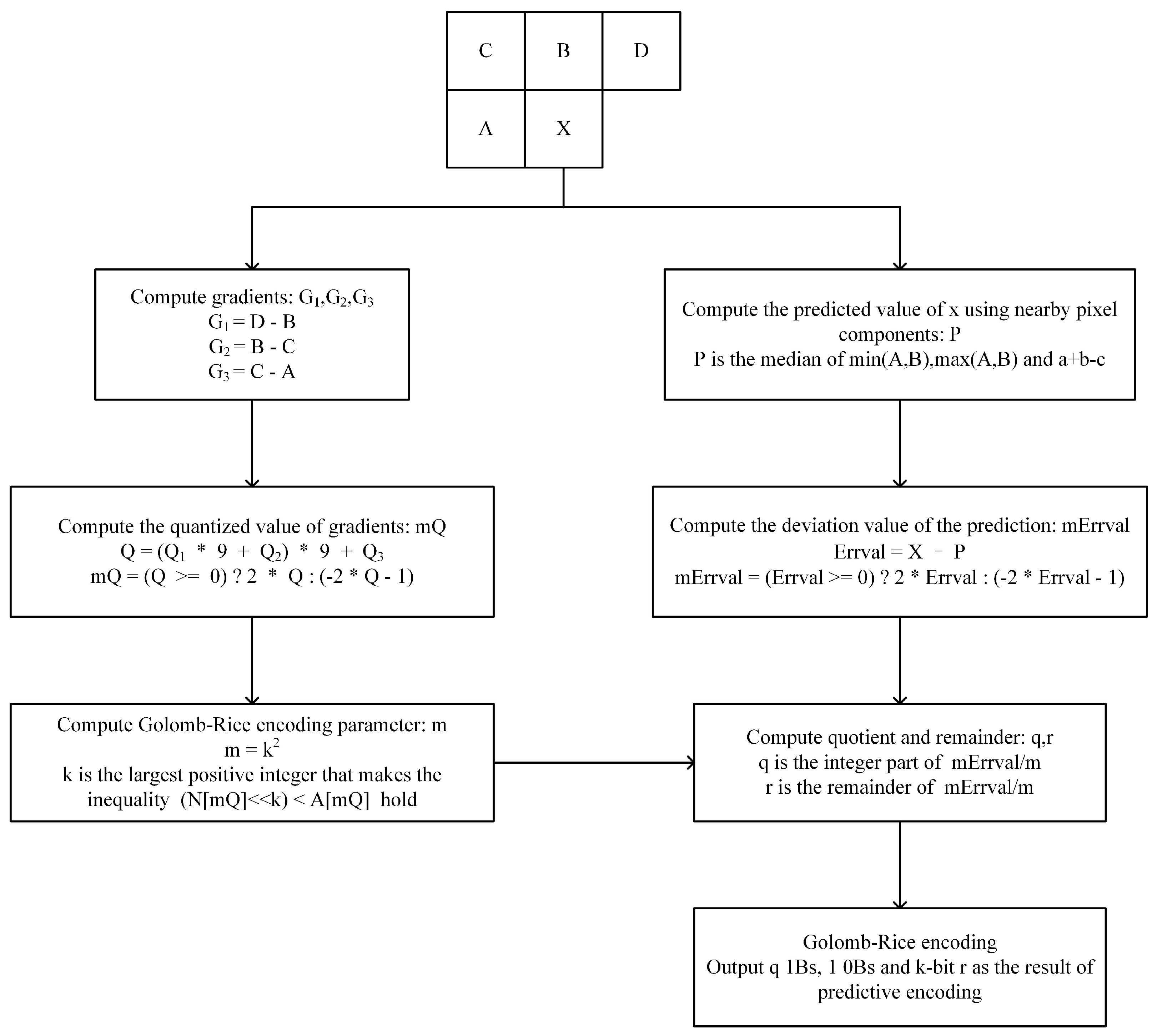
2.3.1. Predictive Coding

This paragraph elucidates a predictive coding strategy that employs gradient quantization and Golomb–Rice coding to efficiently encode and decode pixel component, enhancing image compression by dynamically adjusting based on local component characteristics. As detailed in Figure 3, the predictive coding strategy incorporates a sequential workflow that begins with the computation of gradient values G1, G2, and G3, which are then quantized into Q1, Q2, and Q3 using predefined quantization rules, as shown in Formula (1). The algorithm initializes two significant arrays: A, with a length of 730 elements set to zero, representing the accumulated error values; and N, also 730 elements long but initialized to one, signifying the count of occurrences. These arrays play an integral role in updating the predictive model and are meticulously adjusted with each new Golomb–Rice-coded value that is computed. The update mechanism dictates that for each quantized gradient mQ, the N array at the index mQ is incremented by one, and the A array at the same index is increased by the magnitude of the prediction error mErrval.
Q i = 4 G i 21 3 21 < G i 7 2 7 < G i 3 1 3 < G i < 0 0 0 G i < 0 1 0 G i < 3 2 3 G i < 7 3 7 G i < 21 4 21 G i i = 1 , 2 , 3
During the decompression phase, when the decompressor encounters the flag bit ‘1B’, it activates the inverse Golomb–Rice coding process. This involves the recalibration of the prediction error mErrval, which is then applied alongside the calculated gradient values to reconstruct the original pixel component. By incorporating gradient quantization and Golomb–Rice coding, this predictive coding strategy achieves a dynamic and adaptive compression method that responds to the localized component characteristics within the image, enhancing compression efficiency.

2.3.2. Run-Length Coding

Run-length encoding stands as a testament to the efficiency of image data compression. It is particularly adept at condensing sequences of identical components into a more compact form, significantly optimizing both storage and transmission of image data. This encoding method exploits a common characteristic of images where sequences of repeating components are prevalent, compressing these sequences into a pair that contains a component value and a run-length count. The efficacy of this approach lies in its simplicity and the drastic reduction in data size that it can achieve for images with substantial uniform areas. In the specific implementation at hand in Figure 4, run-length encoding is initiated by encoding the first pixel component in a series of consecutive identical components, which is executed using either predictive or non-coding modes. The encoding mode is selected based on the context and neighborhood of the pixel component, ensuring the most efficient encoding strategy is applied. The subsequent identical pixel components in the sequence are represented by a series of binary 1s, culminating with a binary 0, denoting the end of the run. To illustrate, if a sequence of n identical pixel components is encountered, the initial component is encoded in the selected mode, followed by the run-length encoding flag ‘00B’. The count of n − 1 identical components is then denoted by n − 2 binary 1s (‘1B’) succeeded by a single terminating binary 0 (‘0B’).
During the decompression phase, the algorithm looks for the ‘00B’ flag to signify the beginning of a run-length-encoded sequence. Subsequent bits are read in a continuous stream until a ‘0B’ is reached. The number of ‘1Bs’ encountered prior to the ‘0B’ determines the count n, and the pixel component preceding the ‘00B’ flag is then replicated n + 1 times to accurately reconstruct the original sequence of pixel components. This process ensures that the decompression faithfully restores the image to its original state.
Run-length encoding, thus, serves as a powerful tool in the domain of image compression, capitalizing on the redundancy within component sequences to achieve more efficient data storage and handling. It is particularly effective for images with large areas of uniform color, where it can significantly compress the data without loss of information.

2.3.3. Non-Coding

This study introduces a non-coding strategy to efficiently manage large prediction errors in image compression, ensuring that the encoding of pixel components remains concise and does not exceed 10 bits, even under the most challenging conditions. In predictive coding methods, the occurrence of large prediction errors can potentially inflate the bit count significantly, especially when the error magnitude surpasses 127. Conventionally, this would result in a bit sequence extending beyond 9 bits, plus an additional flag bit, cumulatively exceeding the 10-bit threshold. This inefficiency escalates with the magnitude of the prediction error, rendering the process less optimal. To mitigate this issue, the non-coding mode is introduced as a fallback mechanism. This mode is triggered when large prediction errors are detected, specifically when the error value causes the Golomb–Rice coding to exceed 9 bits. Instead of proceeding with the standard predictive coding that would yield a verbose bit sequence, the algorithm opts for the non-coding mode. It outputs the corresponding flag bit ‘01B’, followed directly by the original, uncompressed value of the current pixel component. This ensures that the encoding for any single pixel component is neatly capped at 10 bits.
During the decompression phase, the algorithm actively monitors for the ‘01B’ flag. Upon its detection, the following 8 bits in the sequence are interpreted as the actual value of the pixel component, without the need for further decoding. This direct method ensures a swift and efficient decompression output. This strategic approach to managing large prediction errors preserves the succinctness and efficiency of the compression algorithm. It provides a robust solution to circumvent the potential expansion of the bit stream, thereby ensuring that the overall compression remains effective even when faced with substantial prediction errors.

3. High-Efficiency Parallel Processing Architecture

The system is based on a parallel processing architecture. It is designed to accelerate image compression and decompression. As shown in Figure 5, a dual-side architecture is used, consisting of a processing system (PS) side and a programmable logic (PL) side. Data in the PS and PL sides are transmitted directly through 128-bit, 256-bit, and 512-bit data channels. The burst lengths for each transmission are 4, 8, and 16, respectively. Each burst transfers 2048 bits of data, equivalent to 256 subpixels, which corresponds to one subpixel channel of a 16 × 16 tile. To achieve maximum system performance, each burst transmission must transfer at least one complete subpixel channel of a tile. Therefore, tile sizes of 4 × 4, 8 × 8, and 16 × 16 were selected for use in the system.
In compression mode, the initial operations are executed on the PS side. Image data are read from memory. During reading, addresses provided by the ARM core are not continuous. Instead, the starting address of each tile row is given, and the burst length is set to match the length of the tile row. This approach allows tiles to be segmented during reading, making tile-based compression easier. The tile data are directly stored in DDR3 SDRAM. Afterward, the tiles are transferred through DMA to the compression module on the PL side. Each multi-core compression module on the PL side has eight compression cores. All cores work in parallel and can process up to eight tiles simultaneously. Since each tile is compressed independently, no parameter dependencies exist. This enables the eight cores to operate fully in sync. After compression, the length of the compressed data from each core is recorded in an AXI Stream FIFO. A signal is then sent to the PS. Based on the recorded length information, the PS transfers the compressed data back to DDR3 memory. When all the data have been compressed, the ARM core sends a command to store the data into external memory. Necessary information is added to form a complete compressed file. For decompression, a similar but reversed process is followed. The compressed file is first read by the PS. Based on the file’s internal information, the PS identifies the position of each tile. The tile data are then transferred to DDR3 SDRAM. DMA is used to move the data into the multi-core decompression module. After finding the header of each tile, the compressed data are assigned to the eight decompression cores. After decompression, the data are transferred back to DDR memory. The PS software reconstructs and stores the final image. The completed image is saved in external memory.
The multi-core compression module is composed of multiple compression cores, a tile scheduling module, and a compressed tile hub module. The tile scheduling component is utilized to efficiently assign tiles to individual compression cores based on the bit width determined by the transmission standard and the specific tile size. Once fetched from the FIFO queue, a tile is directed to the active cores, where the compression algorithm is executed. The cores operate collaboratively to compress the tiles, with length metadata attached before the data are passed to the merging module, which amalgamates the outputs from all cores, preparing the data for subsequent transmission or storage. The efficacy of this module is further enhanced by the implementation of four-stage pipeline technology within the compression cores. The multi-core decompression module consists of several decompression cores, each working in tandem with a compressed tile scheduling module, a tile hub module, and a set of data FIFOs. The data scheduling module plays a pivotal role within this architecture, orchestrating the flow of data through the decompression process. Data are retrieved from the FIFO, matched to the transmission bit width, and allocated to the active decompression cores. Upon receiving the data, the decompression cores employ a decompression algorithm to unravel the compressed information. Once decompressed, the data are transferred to the hub module, where they are combined and prepared for final output. The capabilities of the cores are enhanced by the integration of three dynamic state machines.
The control flow is managed by the ARM-based PS. Data access is ensured through DDR3 memory and its associated control logic. Compression and decompression tasks are handled by the PL side. A robust eight-core parallel design is adopted. By processing eight tiles fully in parallel, high throughput and efficient compression and decompression are achieved.

3.1. Four-Stage Pipeline-Based Compression Architecture

The efficiency of the compression module is further enhanced by implementing pipelining techniques. These techniques are realized through a four-stage pipeline composed of four sequential finite state machines (FSMs), as shown in Figure 6. Each stage is dedicated to a specific task during the compression process.
In the first stage, the pixel components A, B, C, and D, and the target pixel X, are read sequentially. Each reading operation is completed within one clock cycle. After component C is read, the computation of parameter P is initiated. After component D is read, the computations of parameters G1, G2, and G3 are started.
During the first clock cycle of the second pipeline stage, the computed results of P, G1, G2, and G3 are latched. Distributing these calculations across multiple clock cycles significantly improves the operating clock frequency. It should be noted that multi-cycle operations must be implemented with strict timing constraints [22]. This approach is considered a key method for enhancing the pipeline performance. The required clock cycles for each operation are indicated in parentheses.
Certain operations span multiple pipeline stages. For example, the computations of P, G1, G2, and G3 are not completed at the end of the first stage. Instead, they begin as soon as the necessary data become available.
During the second clock cycle of the second pipeline stage, a comparison between A and X is performed. If A and X are identical, the pipeline is terminated, and a run-length code is output. Simultaneously, the calculations of parameters mQ and mErrval are initiated. If run-length encoding is output, the computation process is interrupted. Otherwise, it continues without disruption. After four clock cycles, at the fifth clock cycle of the second stage, the results for mQ and mErrval are completed and latched into registers.
In the first clock cycle of the third pipeline stage, a check is performed to determine whether mErrval exceeds 127. If it does, encoding is skipped, and the pipeline is terminated. If not, the pipeline continues. At the same time, parameter mQ is used as an index to access parameter matrices A and N. After two clock cycles, by the end of the second clock cycle, the A and N matrices are accessed. In the third clock cycle, the indexed parameters are used to calculate parameter k. Meanwhile, updates to matrices A and N are initiated. After two additional clock cycles, at the end of the fourth clock cycle, the value of k is obtained. After three more clock cycles, the updates to matrices A and N are completed.
In the first clock cycle of the fourth pipeline stage, parameters q and r are calculated. These calculations, which started in the fifth clock cycle of the third stage, are completed after two clock cycles. Using the calculated parameters, the Golomb–Rice-encoded result is generated after three more clock cycles. Finally, in the fifth clock cycle, the encoded result is output.

3.2. Dynamic State Machine-Based Decompression Architecture

The functionality of the core is enhanced by integrating three parallel finite state machines (FSMs), with each FSM responsible for a critical phase of the decompression cycle, as shown in Figure 7. In the figure, dashed lines indicate the return of each state machine to the idle state. All three FSMs operate in parallel.
FSM1 is tasked with identifying the appropriate decoding mode and switching between run-length, predictive, and non-coding modes. In the first clock cycle, one bit of data is read. If the bit is “1”, it indicates that the current compression was produced using the predictive mode. Once the decoding mode is determined, neighboring pixels are read. After four clock cycles, four neighboring pixels are obtained, and the calculations for parameters mQ and mErrval are initiated. These calculations are completed after three clock cycles. Subsequently, FSM3 is activated, while FSM1 continues to operate in parallel. After seven clock cycles, FSM1 returns to the idle state and begins decoding new data. During this time, FSM3 uses three clock cycles to read parameters A and N from the parameter matrices by indexing with mQ. Two additional clock cycles are used to calculate parameters k and m. Another two clock cycles are required to decode the Golomb–Rice code and obtain the decompressed pixel. At this point, FSM1 has already returned to the idle state and is ready to receive new data. FSM3 uses two more clock cycles to output the decompressed pixel and simultaneously update the parameter matrices A and N.
When FSM1 returns to idle, it continues receiving one-bit data. If the next bit is “0”, an additional bit is read. If the second bit is also “0”, the run-length mode is selected. Data are continuously read one bit at a time, with each bit checked for “0” or “1”. If a “1” is encountered, the value of A is output as the decompressed result. If a “0” is encountered, the value of A is output, and FSM1 returns to the idle state to decode new data.
If two consecutive bits “1” and “1” are received, the non-coding mode is selected. In this case, four clock cycles are used to read the pixel components A, B, C, and D. One additional clock cycle is used to output the non-coded pixel data. During data output, three clock cycles are used to calculate mQ and mErrval. In the non-coding mode, if mErrval is less than or equal to 127, the parameter matrices must be updated. After completing the calculations, one clock cycle is used to allow FSM1 to return to the idle state. Immediately after the calculation, FSM2 is triggered. FSM2 checks whether mErrval is less than or equal to 127. If not, the state machine continues to execute. If the condition is met, four clock cycles are used to update the A and N matrices before FSM2 returns to idle.
These three FSMs operating in parallel form a dynamic state machine system. FSM1 acts as the main controller, continuously selecting the decoding mode, outputting decompressed data, and delegating parameter calculations and updates to FSM2 and FSM3. The offloading of certain computations to FSM2 and FSM3 accelerates FSM1’s return to the idle state, significantly improving decoding speed. Certain delay clock cycles are intentionally inserted into FSM1 to prevent data from being received too quickly. This ensures that parameter updates can be completed before new data are processed, avoiding the use of outdated parameters.
The term dynamic refers to the behavior of the three parallel finite state machines within the decompression module, which interact and adapt their execution paths in real time based on the input data. Specifically, FSM1 dynamically determines the decoding mode based on the incoming flag bits. Upon selecting a mode, it delegates different computational tasks to FSM2 and FSM3 while continuing to receive new data, thus enabling continuous decoding without waiting for parameter updates to complete. FSM2 and FSM3 are activated conditionally and execute their functions asynchronously, depending on the decoding mode selected and the values of the calculated parameters. The concurrent and conditional operation of these FSMs constitutes dynamic behavior, as the execution flow is not fixed but evolves with the decoding context.

4. Validation and Analysis

4.1. Settings

The system was implemented on the Xilinx ZC706 evaluation board [23], featuring the Zynq-7000 XC7Z045-2FFG900C SoC [24] with two ARM Cortex-A9 processors, 218,600 LUTs, 437,200 FFs, and 19.16 Mb of BRAM. The system was evaluated using five image datasets:
  • ImageNet64 [25]: A downsampled variant of the ImageNet dataset with 50,000 images at 64 × 64 pixels.
  • DIV2K [26]: Contains 100 high-resolution images from diverse scenes.
  • CLIC.p [27]: Comprises 41 high-quality color images, mainly in 2K resolution.
  • CLIC.m [27]: Includes 612K images captured with mobile devices, at predominantly 2K resolution.
  • Kodak [28]: Contains 24 uncompressed color images at 768 × 512 resolution.
The dataset is initially written to FLASH. The ARM processor initializes the DDR3 controller to transfer data from FLASH to DDR3 SDRAM. After transfer, data are sent to the compression system via AXI DMA. The ARM processor manages the flow, sending one tile at a time and retrieving compressed data back to DDR3 SDRAM. If no new data are received, the compression process concludes and an interrupt is sent to the ARM processor with runtime information for efficiency calculations. The compressed data are then stored in FLASH for further analysis.

4.2. Performance of Proposed System

The lossless compression ratio was assessed using tile sizes of 4 × 4, 8 × 8, 16 × 16, and full images. The system can also compress ARGB and RGB images. Comparisons were made with eight codecs, as detailed in Table 1. In this table, the last four rows of data refer to the proposed system, with the values in parentheses indicating the size of the tile. “Full” indicates that the image was not divided into tiles and was instead compressed using the entire image.
The proposed system demonstrated optimal compression performance across various datasets, particularly excelling with full-image and 16 × 16 tile sizes. Notably, the compression efficiency declined with a tile size of 4 × 4, indicating that larger tiles yield better results for diverse image modalities.
Table 2 presents a comparative analysis of the proposed system against several previously reported implementations of lossless image compression algorithms. The comparison includes metrics such as operating frequency, throughput, resource utilization, and the hardware platform used.
From the table, it can be observed that earlier designs, such as the 2009 Spartan-3 implementation [17], operated at relatively low frequencies and achieved limited throughput, reflecting the constraints of older FPGA technology and simpler pipeline structures. More recent works, including those from 2021 [14], 2022 [13], and 2024 [12], have shown substantial improvements in throughput due to enhanced pipeline depth and optimized algorithm–hardware integration. The proposed system, implemented on a Zynq-7000 XC7Z045 platform, achieved the highest throughput among all the compared designs: 480 Mpixels/s at a clock frequency of 300 MHz. This was accomplished while maintaining a moderate resource utilization, suggesting a balanced trade-off between speed and logic complexity. This also demonstrates the effectiveness of the proposed pipelined architecture and tile-based parallel processing strategy.
Table 3 presents a comparative evaluation of the decompression performance between the proposed system and several existing JPEG-LS-based implementations. The comparison includes operating frequency, throughput, logic resource usage, and the FPGA technology employed.
The earliest implementation, reported in 2002 [31], achieved a modest throughput of 7.14 Mpixels/s with 20k equivalent gates, reflecting the technological limitations of the time. Improvements were observed in 2015 [32] with the use of a Virtex-6 platform, where the throughput was increased to 21.07 Mpixels/s at 66.66 MHz using only 1.4k LUTs. A more recent design from 2024 [12], implemented on a Zynq-7000 XC7Z020, demonstrated further gains, with a throughput of 37.02 Mpixels/s at 128.5 MHz, utilizing just 789 LUTs. The proposed system, implemented on a Zynq-7000 XC7Z045, significantly outperforms all previous designs. It achieves a throughput of 372 Mpixels/s at 400 MHz, representing an order-of-magnitude improvement over the next best result. In conclusion, the proposed decompression architecture demonstrates a substantial advancement in both speed and efficiency.
Our analysis of the performance of the proposed implementation also focuses on throughput, resource utilization, other resources, energy consumption, consistency, the impact of image patterns, and the effect of tile size.
  • Throughput: Significant improvements were achieved by the proposed architecture. The compression module operates at a clock frequency of 300 MHz, with a maximum throughput of 480 Msubpixel/s. Pipelining is utilized in the implementation, ensuring that runtime throughput is not affected by the data themselves. One compression core processes a subpixel every five clock cycles. Throughput is calculated based on the clock frequency and the number of compression cores. Latency varies depending on the type of pixel data. When run-length coding is applied, latency is 7 clock cycles. When non-coding is applied, latency increases to 11 cycles. When predictive coding is used, latency reaches 25 cycles. Under conditions of full-speed pipelined operation, latency is effectively masked by continuous processing. The execution time is estimated using the throughput and image size. Specifically, the total data size of the image is divided by the throughput to approximate the processing duration. However, the actual processing time is influenced by the content of the image. The decompression module operates at a clock frequency of 400 MHz, achieving a maximum throughput of 372 Msubpixel/s, which is more than three times that of naive implementations. The throughput of the decompression module is influenced by the data, with varying numbers of clock cycles required for processing by different decompression cores.
  • Resource utilization: The resource utilization of the proposed system is detailed in Table 4. In addition to reporting the overall resource usage of the proposed system, Table 4 provides a comprehensive breakdown of the resource utilization for both the compression and decompression modules.
  • Other resources: The system effectively minimized memory consumption by employing FIFO for tile buffering and DDR3 SDRAM for tile and parameter storage, optimized for various tile sizes. In total, four AXI-STREAM interfaces with widths of 128 bits, 256 bits, and 512 bits were utilized in both the compression and decompression modules. Additionally, an extra AXI-STREAM interface FIFO was implemented for the transmission of compressed information. At least 512 MB of high-speed memory, such as DDR2 or higher, is required for the implementation of this system. FLASH memory cards were selected as the external storage medium for data retention.
  • Energy consumption: The system power consumption was measured to be 2.585 W at room temperature. Under extreme low temperatures of −35 °C, power consumption was reduced to 2.37 W. At an extreme high temperature of 125 °C, power consumption was increased to 3.441 W.
  • Impact of image patterns: The smoothness of images notably influenced the compression performance. Images with minimal grayscale variation yielded better compression ratios, while those with high variability performed less effectively.
  • Effect of tile size: Testing various tile sizes indicated a moderate increase in compression ratio with larger sizes. An optimal tile size of 16 × 16 was identified, balancing compression efficiency with resource constraints.
  • Consistency: Since the proposed system is implemented using a lossless compression algorithm, the images before compression and after decompression are expected to be completely identical—that is, consistency should be preserved. Therefore, the decompressed images were compared with the original images on a one-to-one basis. Upon inspection, it was confirmed that the decompressed images were completely consistent with the original ones.

5. Conclusions

In conclusion, this study presents a novel high-throughput, lossless image compression and decompression system designed to meet the growing demands of modern data-intensive applications. By integrating a hybrid compression strategy that incorporates run-length coding, predictive coding, and a non-coding mechanism, the proposed system optimally compresses various image components. Implementing the algorithm on an FPGA-based platform allows for parallel processing and efficient resource utilization, significantly improving throughput. The system’s tile-based approach, coupled with a multi-core architecture, further enhances its parallel processing capabilities. Additionally, the use of a five-stage pipeline in the compression process and three dynamic state machines in the decompression process ensures high clock frequencies and overall performance efficiency. This solution demonstrates clear advantages over existing methods, making it a robust and scalable option for real-time image processing tasks where high throughput and lossless quality are essential.
The system is implemented on Xilinx Zynq platform. As it is not purely a PL-side design, participation from the PS side is required. On other platforms, the PL-side code can be migrated by updating the IP cores. However, migrating the PS-side code is more challenging. This is due to differences in the connection methods and communication protocols between PS and PL components across platforms. These variations increase the complexity of cross-platform migration. Migration is feasible within the Zynq family, for example, the design can be ported to the ZCU104 UltraScale+ platform. In ASIC implementations, the PS must be replaced with a soft-core processor, which also adds to the migration difficulty.
In the future, further acceleration of the decompression process will be pursued. Pipelining techniques will be applied to the decompression algorithm, and the pipeline structure of the compression algorithm will also be optimized. A deeper pipeline with additional stages will be adopted to increase both operating frequency and throughput. The method will also be considered for deployment in radiation-prone environments, such as satellite systems and medical applications, where tile-based compression can enhance radiation resistance.

Author Contributions

Methodology, X.L.; software, X.L.; validation, X.L. and L.Z.; formal analysis, X.L.; investigation, X.L. and L.Z.; resources, X.L. and Y.Z.; data curation, X.L.; writing—original draft preparation, X.L.; writing—review and editing, L.Z.; supervision, Y.Z.; project administration, X.L. All authors have read and agreed to the published version of the manuscript.

Funding

This research was funded by the Key Program of the Chinese Academy of Sciences, grant number E16505B31S. The APC was funded by the same source.

Institutional Review Board Statement

Not applicable.

Informed Consent Statement

Not applicable.

Data Availability Statement

The raw data supporting the conclusions of this article will be made available by the authors on request.

Conflicts of Interest

The authors declare no conflicts of interest.

References

  1. Mentzer, F.; Agustsson, E.; Tschannen, M.; Timofte, R.; Gool, L.V. Practical full resolution learned lossless image compression. In Proceedings of the IEEE/CVF Conference on Computer Vision and Pattern Recognition, Long Beach, CA, USA, 15–20 June 2019; pp. 10629–10638. [Google Scholar]
  2. Si, Z.; Shen, K. Research on the WebP image format. In Advanced Graphic Communications, Packaging Technology and Materials; Springer: Berlin/Heidelberg, Germany, 2016; pp. 271–277. [Google Scholar]
  3. Miaou, S.G.; Ke, F.S.; Chen, S.C. A Lossless Compression Method for Medical Image Sequences Using JPEG-LS and Interframe Coding. IEEE Trans. Inf. Technol. Biomed. 2009, 13, 818–821. [Google Scholar] [CrossRef] [PubMed]
  4. Zhang, D.; Yang, M.; Tao, J.; Wang, Y.; Liu, B.; Bukhari, D. Extraction of tongue contour in real-time magnetic resonance imaging sequences. In Proceedings of the 2016 IEEE International Conference on Acoustics, Speech and Signal Processing (ICASSP), Shanghai, China, 20–25 March 2016; pp. 937–941. [Google Scholar] [CrossRef]
  5. Tong, L.Y.; Lin, J.B.; Deng, Y.Y.; Ji, K.F.; Hou, J.F.; Wang, Q.; Yang, X. Lossless Compression Method for the Magnetic and Helioseismic Imager (MHI) Payload. Res. Astron. Astrophys. 2024, 24, 045019. [Google Scholar] [CrossRef]
  6. Rane, S.; Sapiro, G. Evaluation of JPEG-LS, the new lossless and controlled-lossy still image compression standard, for compression of high-resolution elevation data. IEEE Trans. Geosci. Remote. Sens. 2001, 39, 2298–2306. [Google Scholar] [CrossRef]
  7. Verstockt, S.; De Bruyne, S.; Poppe, C.; Lambert, P.; Van de Walle, R. Multi-view Object Localization in H.264/AVC Compressed Domain. In Proceedings of the 2009 Sixth IEEE International Conference on Advanced Video and Signal Based Surveillance, Genoa, Italy, 2–4 September 2009; pp. 370–374. [Google Scholar] [CrossRef]
  8. Albalawi, U.; Mohanty, S.P.; Kougianos, E. A Hardware Architecture for Better Portable Graphics (BPG) Compression Encoder. In Proceedings of the 2015 IEEE International Symposium on Nanoelectronic and Information Systems, Didcot, UK, 8–10 October 2015; pp. 291–296. [Google Scholar] [CrossRef]
  9. Wu, X.; Choi, W.K.; Bao, P. L/sub /spl infin//-constrained high-fidelity image compression via adaptive context modeling. In Proceedings of the DCC ’97. Data Compression Conference, Snowbird, UT, USA, 25–27 March 1997; pp. 91–100. [Google Scholar] [CrossRef]
  10. Öztürk, E.; Mesut, A. Performance Evaluation of JPEG Standards, WebP and PNG in Terms of Compression Ratio and Time for Lossless Encoding. In Proceedings of the 2021 6th International Conference on Computer Science and Engineering (UBMK), Ankara, Turkey, 15–17 September 2021; pp. 15–20. [Google Scholar] [CrossRef]
  11. Weinberger, M.; Seroussi, G.; Sapiro, G. The LOCO-I lossless image compression algorithm: Principles and standardization into JPEG-LS. IEEE Trans. Image Process. 2000, 9, 1309–1324. [Google Scholar] [CrossRef] [PubMed]
  12. Liu, F.; Chen, X.; Liao, Z.; Yang, C. Adaptive Pipeline Hardware Architecture Design and Implementation for Image Lossless Compression/Decompression Based on JPEG-LS. IEEE Access 2024, 12, 5393–5403. [Google Scholar] [CrossRef]
  13. Dong, X.; Li, P. Implementation of A Real-Time Lossless JPEG-LS Compression Algorithm Based on FPGA. In Proceedings of the 2022 14th International Conference on Signal Processing Systems (ICSPS), Zhenjiang, China, 18–20 November 2022; pp. 523–528. [Google Scholar] [CrossRef]
  14. Wang, X.; Gong, L.; Wang, C.; Li, X.; Zhou, X. UH-JLS: A Parallel Ultra-High Throughput JPEG-LS Encoding Architecture for Lossless Image Compression. In Proceedings of the 2021 IEEE 39th International Conference on Computer Design (ICCD), Virtual, 24–27 October 2021; pp. 335–343. [Google Scholar] [CrossRef]
  15. Ferretti, M.; Boffadossi, M. A parallel pipelined implementation of LOCO-I for JPEG-LS. In Proceedings of the 17th International Conference on Pattern Recognition (ICPR), Cambridge, UK, 23–26 August 2004; Volume 1, pp. 769–772. [Google Scholar] [CrossRef]
  16. Klimesh, M.; Stanton, V.; Watola, D. Hardware implementation of a lossless image compression algorithm using a field programmable gate array. Mars 2001, 4, 5–72. [Google Scholar]
  17. Merlino, P.; Abramo, A. A Fully Pipelined Architecture for the LOCO-I Compression Algorithm. IEEE Trans. Very Large Scale Integr. (VLSI) Syst. 2009, 17, 967–971. [Google Scholar] [CrossRef]
  18. Mert, Y.M. FPGA-based JPEG-LS encoder for onboard real-time lossless image compression. In Proceedings of the Satellite Data Compression, Communications, and Processing XI, Baltimore, MD, USA, 23–24 April 2015; Volume 9501, pp. 45–52. [Google Scholar]
  19. Varshney, A.; Suneetha, K.; Yadav, D.K. Analyzing the Performance of Different Compactor Techniques in Data Compression Source Coding. In Proceedings of the 2024 International Conference on Optimization Computing and Wireless Communication (ICOCWC), Debre Tabor, Ethiopia, 29–30 January 2024; pp. 1–6. [Google Scholar] [CrossRef]
  20. Akhtar, M.B.; Qureshi, A.M.; ul Islam, Q. Optimized run length coding for jpeg image compression used in space research program of IST. In Proceedings of the International Conference on Computer Networks and Information Technology, Paphos, Cyprus, 31 August–2 September 2011; pp. 81–85. [Google Scholar] [CrossRef]
  21. Golomb, S. Run-length encodings (Corresp.). IEEE Trans. Inf. Theory 1966, 12, 399–401. [Google Scholar] [CrossRef]
  22. xilinx. Vivado Design Suite User Guide Using Constraints (UG903). 2022. Available online: https://docs.amd.com/r/en-US/ug903-vivado-using-constraints (accessed on 20 December 2024).
  23. xilinx. ZC706 Evaluation Board for the Zynq-7000 XC7Z045 SoC User Guide (UG954). 2019. Available online: https://docs.amd.com/v/u/en-US/ug954-zc706-eval-board-xc7z045-ap-soc (accessed on 6 August 2019).
  24. xilinx. Zynq-7000 SoC Data Sheet: Overview (DS190). 2018. Available online: https://docs.amd.com/v/u/en-US/ds190-Zynq-7000-Overview (accessed on 2 July 2018).
  25. Chrabaszcz, P.; Loshchilov, I.; Hutter, F. A Downsampled Variant of ImageNet as an Alternative to the CIFAR datasets. arXiv 2017, arXiv:1707.08819. [Google Scholar]
  26. Chen, S.; Han, Z.; Dai, E.; Jia, X.; Liu, Z.; Liu, X.; Zou, X.; Xu, C.; Liu, J.; Tian, Q. Unsupervised Image Super-Resolution with an Indirect Supervised Path. In Proceedings of the 2020 IEEE/CVF Conference on Computer Vision and Pattern Recognition Workshops (CVPRW), Seattle, WA, USA, 14–19 June 2020; pp. 1924–1933. [Google Scholar] [CrossRef]
  27. Ma, G.; Chai, Y.; Jiang, T.; Lu, M.; Chen, T. TinyLIC-High efficiency lossy image compression method. arXiv 2024, arXiv:2402.11164. [Google Scholar]
  28. Minnen, D.; Toderici, G.; Covell, M.; Chinen, T.; Johnston, N.; Shor, J.; Hwang, S.J.; Vincent, D.; Singh, S. Spatially adaptive image compression using a tiled deep network. In Proceedings of the 2017 IEEE International Conference on Image Processing (ICIP), Beijing, China, 17–20 September 2017; pp. 2796–2800. [Google Scholar]
  29. Skodras, A.; Christopoulos, C.; Ebrahimi, T. The JPEG 2000 still image compression standard. IEEE Signal Process. Mag. 2001, 18, 36–58. [Google Scholar] [CrossRef]
  30. Chen, L.; Yan, L.; Sang, H.; Zhang, T. High-Throughput Architecture for Both Lossless and Near-lossless Compression Modes of LOCO-I Algorithm. IEEE Trans. Circuits Syst. Video Technol. 2019, 29, 3754–3764. [Google Scholar] [CrossRef]
  31. Savakis, A.; Piorun, M. Benchmarking and hardware implementation of JPEG-LS. In Proceedings of the International Conference on Image Processing, Rochester, NY, USA, 22–25 September 2002; Volume 2, p. II. [Google Scholar] [CrossRef]
  32. Deng, L.; Huang, Z. The FPGA design of JPEG-LS image lossless decompression IP core. In Proceedings of the 2015 Chinese Automation Congress (CAC), Wuhan, China, 27–29 November 2015; pp. 2199–2203. [Google Scholar] [CrossRef]
Figure 1. Process of the compression algorithm.
Applsci 15 06017 g001
Figure 2. Process of the decompression algorithm.
Applsci 15 06017 g002
Figure 3. The process of predictive coding.
Applsci 15 06017 g003
Figure 4. Example of run-length coding.
Applsci 15 06017 g004
Figure 5. Architecture diagram.
Applsci 15 06017 g005
Figure 6. Four-stage pipeline for compression core.
Applsci 15 06017 g006
Figure 7. Dynamic state machine of decompression core.
Applsci 15 06017 g007
Table 1. Comparison with other methods using compression ratio metric.
MethodImageNet64DIV2KCLIC.pCLIC.mKodak
PNG [10]1.221.301.341.341.29
JPEG-LS [11]1.281.501.541.651.46
CALIC [9]1.261.481.531.621.45
JPEG2000 [29]1.261.471.511.581.45
WebP [2]1.291.471.521.571.45
BPG [8]1.291.431.481.541.42
Proposed (4 × 4)1.091.271.381.411.27
Proposed (8 × 8)1.271.471.501.621.44
Proposed (16 × 16)1.281.501.521.641.45
Proposed (full)1.281.501.531.641.45
Table 2. Compression performance comparison with existing implementations.
WorkTechnologyResourceFrequency (MHz)Throughput (Mpixel/s)Algorithm
2009 [17]Spartan-336k equivalent gates2121LOCO-I
2018 [30]Virtex-6 XC6VCX75T8354 slices51.68451.684LOCO-I
2021 [14]Virtex-7 XC7VX48518.7k LUT264263.98JPEG-LS
2022 [13]Kintex-7 XC7K70T10.25k LUT103100JPEG-LS
2024 [12]Zynq-7000 XC7Z0201.3k LUT108.643.03JPEG-LS
ProposedZynq-7000 XC7Z0458437 slices300480-
Table 3. Decompression performance comparison with existing implementations.
WorkTechnologyResourceFrequency (MHz)Throughput (Mpixel/s)Algorithm
2002 [31]-20k equivalent gates-7.14JPEG-LS
2015 [32]Virtex-6 XC6VSX315T1.4k LUT66.6621.07JPEG-LS
2024 [12]Zynq-7000 XC7Z0201.1k LUT128.537.02JPEG-LS
ProposedZynq-7000 XC7Z0457422 slices400372-
Table 4. Resource utilization.
NameSystemCompression ModuleDecompression Module
Slice LUTs887542114720268
Block RAM310.5226.550.5
Bonded IOPADS13000
BUFGCTRL400
MMCME2_ADV200
Slice Registers8515650353974
F7 Muxes1718314264
F8 Muxes2257295
Slice2985084377422
LUT as Logic840692099519848
LUT as Memory4685152420
Disclaimer/Publisher’s Note: The statements, opinions and data contained in all publications are solely those of the individual author(s) and contributor(s) and not of MDPI and/or the editor(s). MDPI and/or the editor(s) disclaim responsibility for any injury to people or property resulting from any ideas, methods, instructions or products referred to in the content.

