1. Introduction
Lightning impulse overvoltages are one of the most important causes of damage to electrical power transformers. These transient phenomena can generate extremely high voltages, far exceeding the rated values of the equipment, and can lead to insulation damage, winding penetration and, in extreme cases, the complete destruction of the transformer.
The occurrence of these surges can be caused by direct atmospheric discharges (direct lightning strikes), switching operations and maneuvers on the network.
If the lightning strike does not strike the line directly, the electromagnetic field that is generated by the discharge may induce voltages in the line conductors and, by coupling, in the transformer windings.
Switching operations and network maneuvers can also generate transient surges that can affect transformers [
1,
2,
3,
4,
5,
6,
7,
8].
Overvoltages occurring in the transformer can have adverse effects on its structure such as the following [
9,
10,
11,
12,
13]:
Damage to the insulation: If surges exceed the insulation breakdown voltage, they can lead to internal electrical discharges and the gradual degradation of insulating materials.
Winding perforation: In severe situations, surges can cause physical damage to windings and internal short circuits, as well as major transformer damage.
High currents generated by surges can produce significant electrodynamic forces, which can deform or destroy the mechanical components of the transformer.
Repeated overvoltages can accelerate the aging process of insulation.
In order to protect transformers against overvoltages occurring following a lightning impulse, several technical solutions and measures have been adopted, including the following [
10,
11,
12,
13,
14,
15,
16]:
The use of lightning arresters that directly capture lightning discharges and conduct them safely to earth;
The use of variable-resistance arresters to limit the amplitude of overvoltages by earthing in the event of the occurrence of excessive voltages;
The correct sizing of transformer insulation to withstand anticipated surges;
The use of metallic shields to reduce electromagnetic coupling between conductors and limit induced voltages;
Continuous monitoring of network parameters and automatic tripping of protective devices in case of anomalies.
A wide range of studies have been carried out to understand the transient voltages occurring at the impulse at the transformer windings and to analyze the effects that are generated by this transient phenomenon.
In order to correctly assess the risk of damage caused by overvoltages, researchers have carried out detailed research involving the following [
4,
5,
6,
7,
8,
11,
12,
13,
14,
15,
16,
17,
18,
19,
20,
21,
22,
23,
24,
25]:
Mathematical network modeling: simulating the behavior of the network under surge conditions to determine the level and wave shape of voltage surges that can occur at transformer terminals through a mathematical approach [
11,
16,
17,
18,
19,
20,
23,
25];
Field measurements to record actual overvoltages during atmospheric events to validate mathematical models and calibrate protective equipment [
9,
14,
21,
24];
Assessments of the frequency and severity of surge events to determine the level of risk and to properly size protective systems [
4,
5,
6,
7,
8,
15];
The implementation of standards and regulations defining the requirements for the design and operation of electrical systems to ensure surge protection [
4,
5,
6,
7,
8,
22];
The development of insulating materials with improved characteristics to increase transformers ability to withstand surges and achieve an effective grounding system is essential to dissipate the electrical energy of lightning and reduce step potentials [
12,
13,
14,
20,
23].
Due to the fact that the amplitude and frequency of the energizing voltage are time-varying, the transient voltages occurring in the transformer windings at lightning impulse cannot be fitted into a model.
There is no agreement/consensus as to the contribution of the magnetic core in determining the amplitude, oscillation frequency or attenuation of the resulting surge voltage at various portions of the windings.
The phenomenon of lightning impulse overvoltages has been of particular interest to researchers/specialists in the field, and mathematical models, simulations and analysis have been carried out to predetermine the overvoltages occurring at the transformer level in order to avoid fault situations.
It was proved that a model based on coupled circuits using leakage inductances as the concentration parameters can provide the magnitude of the magnetic flux, using the magnetomotive voltages whose magnitude/value depends on the value of the electric current that is generated in the electric circuit as sources. The derivative of the magnetic flux provides the magnitude of the electric current containing the resistances and capacitances. The disadvantage of such a model lies in using details from the transformer design in determining the leakage inductances and capacitances [
24,
26,
27,
28,
29,
30,
31].
The method proposed/presented in this paper was applied on a TTUS—ONAN/ONAF 31.5/40MVA, 110/5/6.6 kV power transformer, and the analytical/simulated results were validated by actual testing of the transformers under study, demonstrating that the relative error resulting from the comparison of the results is small.
2. Analytical Method for Determining the Overvoltages That Are Transmitted Between Transformer Windings
The concept of lightning impulse overvoltage in transformers defines lightning impulse voltage as an overvoltage that is generated by a sudden rise in voltage under the action of a magnetic field or sudden load. This type of overvoltage often causes damage to the insulation system and circuit components of transformers and, in severe cases, can even cause accidents such as fires and explosions.
As already mentioned in the first part of this paper, the analytical method presented for the determination of the value of the overvoltages that run through the transformer windings when the transformer is subjected to a lightning impulse has two defining components: the inductive component and the capacitive component. The process of determining the analytical relationships involves describing in a step-by-step manner how the transmission/propagation of overvoltages from the winding that is subjected to the voltage impulse to the winding with one terminal free and the other earthed occurs. The steps are as follows [
20,
23,
24]:
Determination of the component of the overvoltage that is transmitted by electromagnetic induction;
Determination of the component of overvoltage that is transmitted by capacitive coupling;
Determination of the oscillating component of the overvoltage that is transmitted between the transformer windings;
Determination of the overvoltage that is transmitted between the primary and secondary windings;
Determination of the overvoltage that is transmitted to the tertiary winding.
2.1. Determination of the Component of the Overvoltage That Is Transmitted by Electromagnetic Induction
The standard pulse wave is depicted in
Figure 1. The actual definition is precise: for the lightning pulse, the front time (T
1) is 1.2 µs and the back time (T
2) is 50 µs. In the field, the lightning pulse wave can take various shapes [
1,
2,
3,
5,
6,
7,
8].
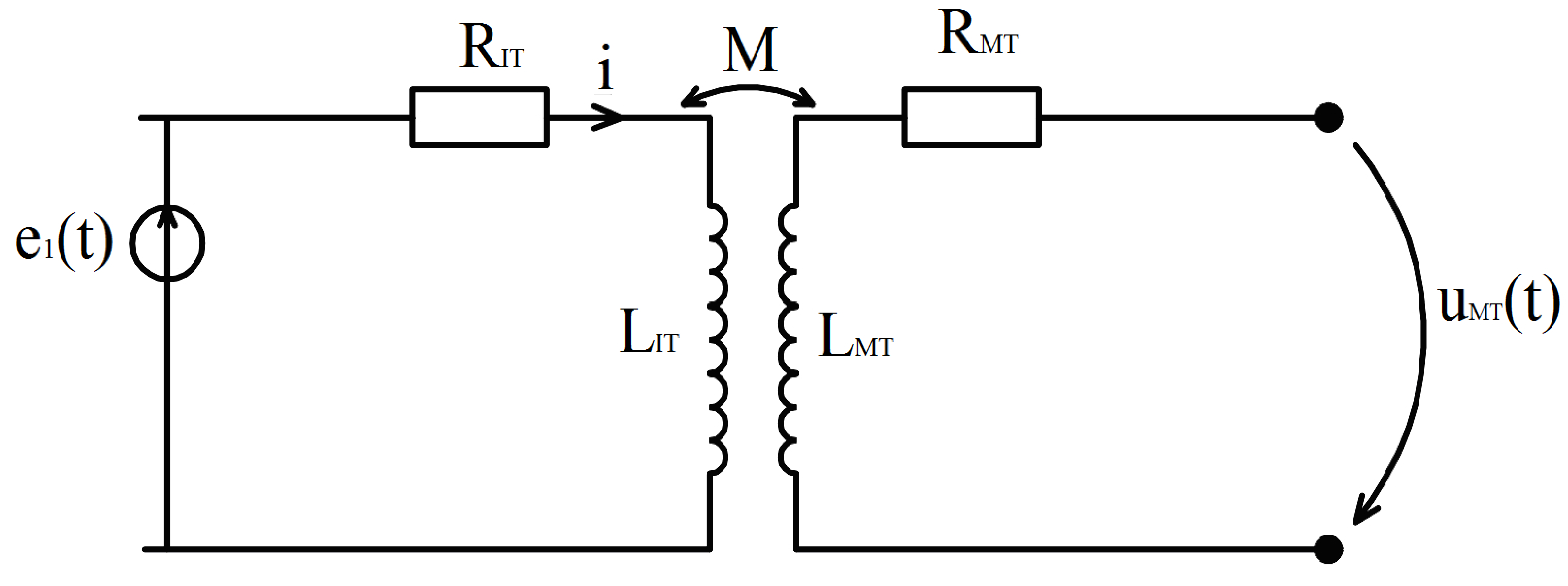
The configuration of the circuit that was analyzed to evaluate the overvoltage that is transmitted by electromagnetic induction is described in
Figure 2, where
is the standard lightning impulse; its analytical expression is as follows [
23]:
where
and are specific time constants of the lightning impulse t;
is the maximum amplitude of the lightning impulse;
is the resistance of the high-voltage (IT) winding;
is the inductance of the high-voltage winding;
is the resistance of the medium-voltage (MT) winding;
is the inductance of the medium-voltage winding;
M is the mutual inductance between the IT and MT windings.
The equations describing the circuit shown in
Figure 2 are as follows:
In the Laplace domain, we have the following relations [
1,
32,
33,
34]:
We note the time constant of the high-voltage winding as follows:
Knowing that the Laplace image
has in the time domain the expression
[
35], the following expression in the time domain can be used for the voltage that is transmitted by electromagnetic induction [
20,
23]:
Note that the value of
has a value up to
t = 2 μs, given by Equation (12), and for times exceeding this value,
will be determined according to the following [
24]:
where:
is the resistance value of the conductor in the pulsating electric field ω;
is the resistance value when a direct current flows through the conductor;
is the cross-section of the conductor;
is the surface through which the pulsating electric current flows, ω.
2.2. Determination of the Component of Overvoltage That Is Transmitted by Capacitive Coupling
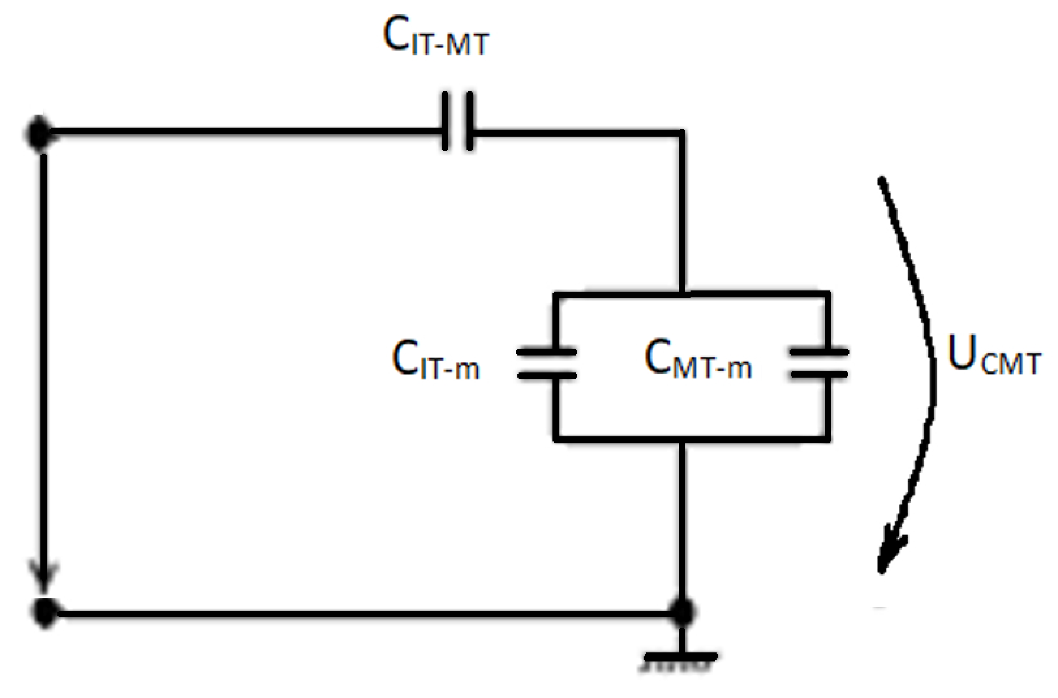
The lightning impulse voltage is applied to the input of the high-voltage winding and is distributed to the secondary winding terminal according to the capacitive circuit that can be seen in
Figure 3.
The lightning impulse at the non-energized winding terminal is split by and .
The equivalent capacitance is given by the following relation (13) [
20,
23]:
where
is the series capacity of the winding;
is the capacity of the winding with respect to the magnetic core; and
is the capacity of the winding relative to the transformer tank.
2.3. Determination of the Oscillating Component of the Overvoltage That Is Transmitted Between the Transformer Windings
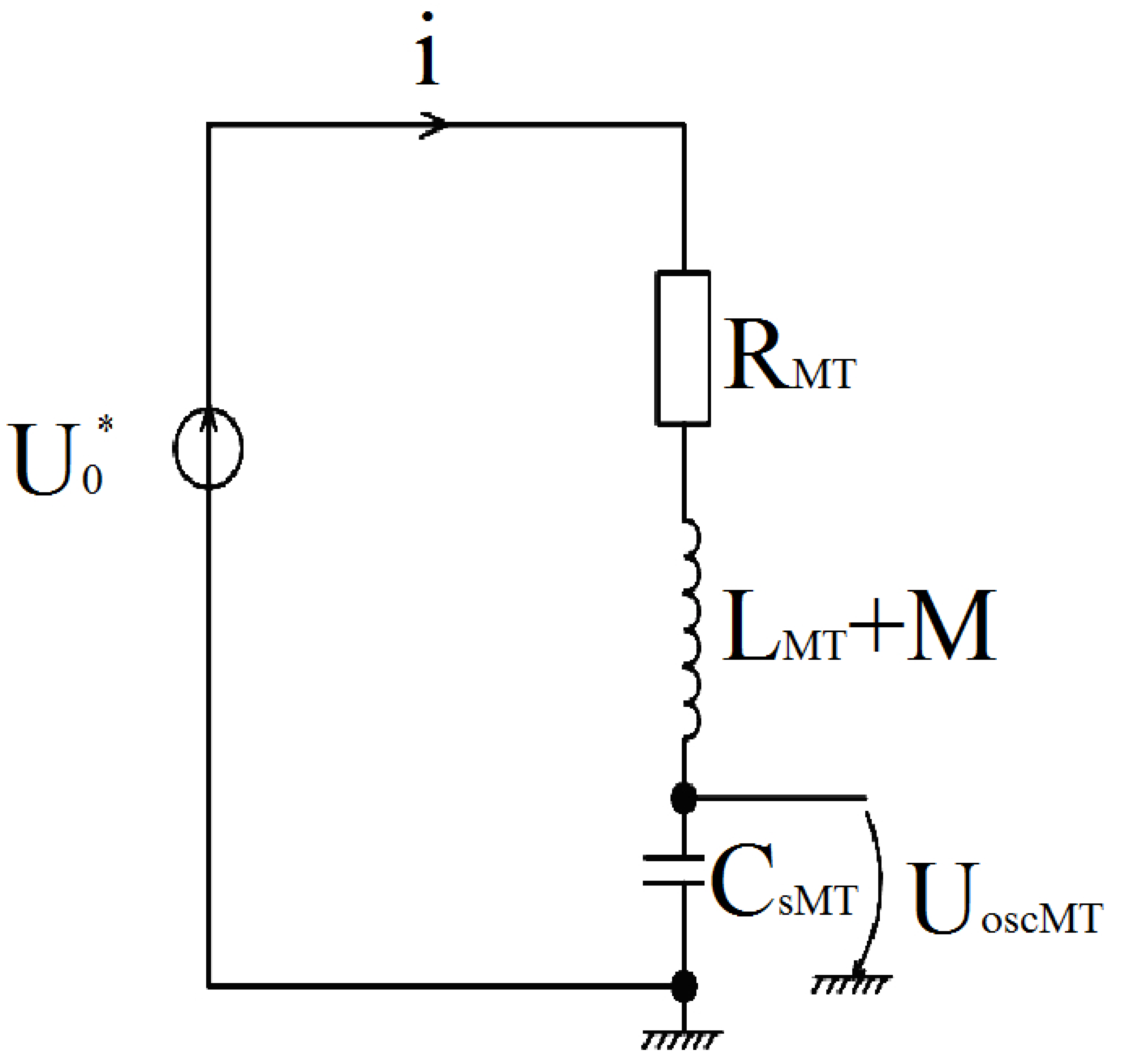
For the calculation of the oscillating component, the response of the equivalent winding circuit to the application of a stepped wave with amplitude
must be determined. The analyzed circuit is shown in
Figure 4. Under these conditions, the shape of the amplitude stepped wave
is given by the following relation (16) [
20,
23]:
Using this notation, we obtain the following:
We obtain the following equation:
Equation (21) characterizes the free voltage component at the capacitance terminals
. The roots of Equation (21) are as follows:
The free-form solution is the following relationship:
According to Euler relations, this becomes the following:
In order to determine the relationships between the oscillatory components of the surges propagating at the windings, we summed the transient response function for the energization with a step impulse voltage,
, and used the function characterizing the actual voltage, with which the MT winding is energized (see Equation (15)). Then, the Duhamel integral was applied to superpose a finite set of step functions with amplitudes and retardations that were conveniently chosen according to Equation (24) [
20,
23]:
where
T is the significant duration of the input voltage.
Because
has the value zero for
t = 0, the relation (25) becomes as follows:
Applying the integral by parts, we obtain the following [
35]:
where
;
;
is the delay step.
The second term of Equation (27) is developed as follows [
20,
23,
35]:
For delay step values in the range seconds, exponentials have values that are approximately equal to one.
According to [
35], the primitive of the integral is given by the following relation:
taking into consideration that
gives the following expression for the integral
[
20,
23,
35,
36]:
This gives the expression of the oscillating voltage at the terminals of the secondary winding [
20,
23]:
where
is the time resulting from lightning impulse sampling;
; is the number of sampling steps;
is the sampling step.
2.4. Determination of the Overvoltage That Is Transmitted Between the Primary and Secondary Windings
When the primary winding (IT) is subjected to the lightning impulse, an overvoltage is propagated at the terminals of the secondary winding (MT), which is generated by the superposition of the waveforms defined by Equations (11) and (30) and has the following equation [
20,
23,
36]:
where
is the time resulting from lightning impulse sampling;
; is the number of sampling steps;
is the sampling step.
2.5. Determination of the Overvoltage That Is Transmitted to the Tertiary Winding
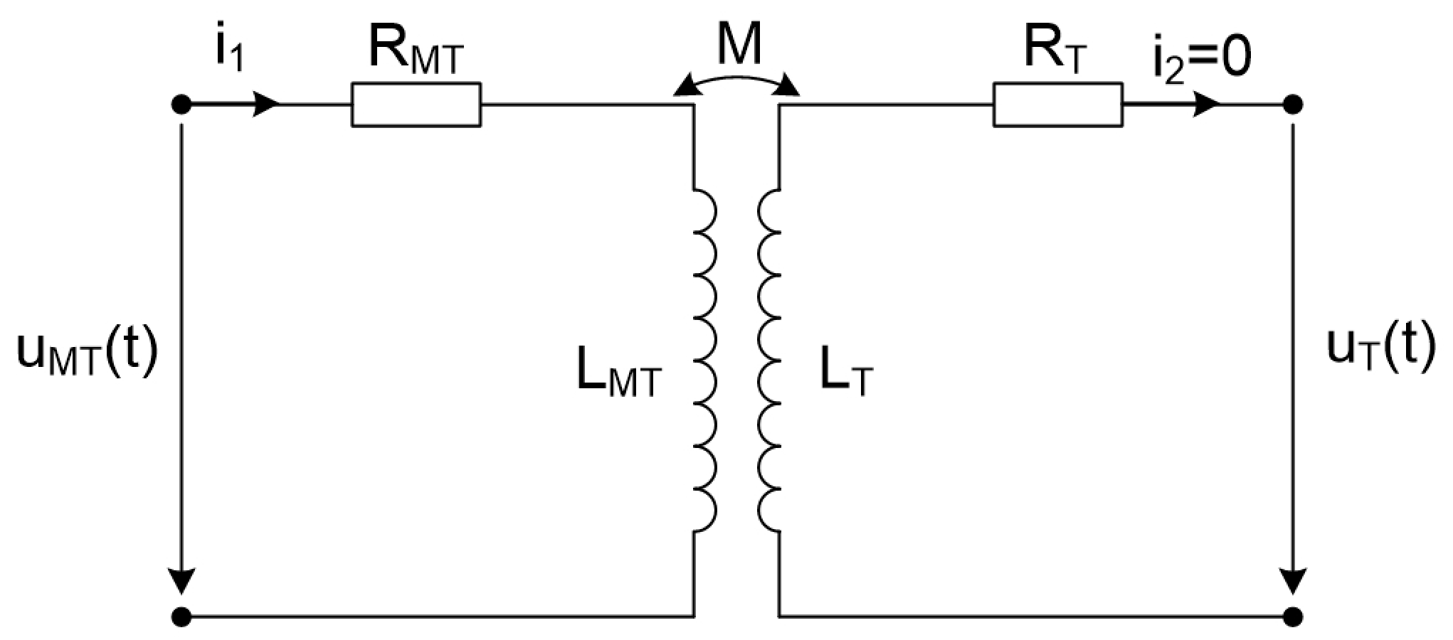
The MT winding, because it is connected to earth at one end, acts as a screen between the IT windings and the tertiary winding (T). Consequently, the overvoltage that is transmitted to T is the product of the inductive transfer between the MT and T windings (see
Figure 5) [
20,
23,
36].
but
; it then follows that
because
.
where
and
are the number of turns of the tertiary and secondary windings (MT).
3. Simulation Results
The simulation of the analyzed phenomenon was performed with MATLAB R2021b version. The code for determining the transmitted overvoltages was written in C language using the Math Script RT module [
37].
The real parameters of the power transformer are as follows:
- -
IT winding resistance: .
- -
MT winding resistance: .
- -
T winding resistance: .
- -
IT winding inductance: .
- -
MT winding inductance: .
- -
the inductance of the T winding: .
- -
T winding–MT winding capacitance: .
- -
MT winding–IT winding capacitance: .
- -
Serial capacitance of MT winding: .
- -
Capacitance of MT winding to ground: .
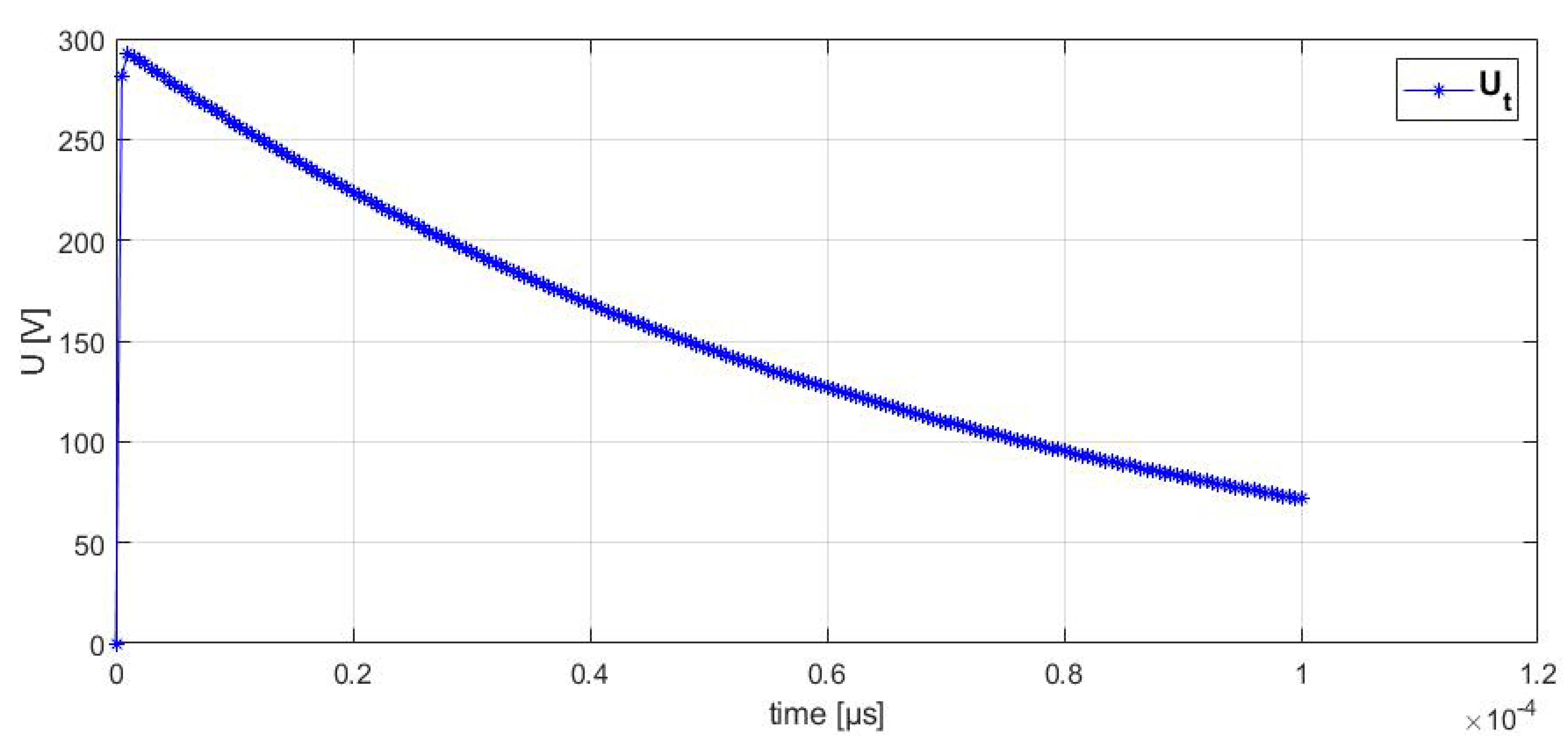
For both the simulation and testing, the value of the pulse that was applied to the transformer was set to 292.4 V, while the value of the voltage pulse that was applied in the laboratory tests was gradually increased according to current standards (see
Figure 6).
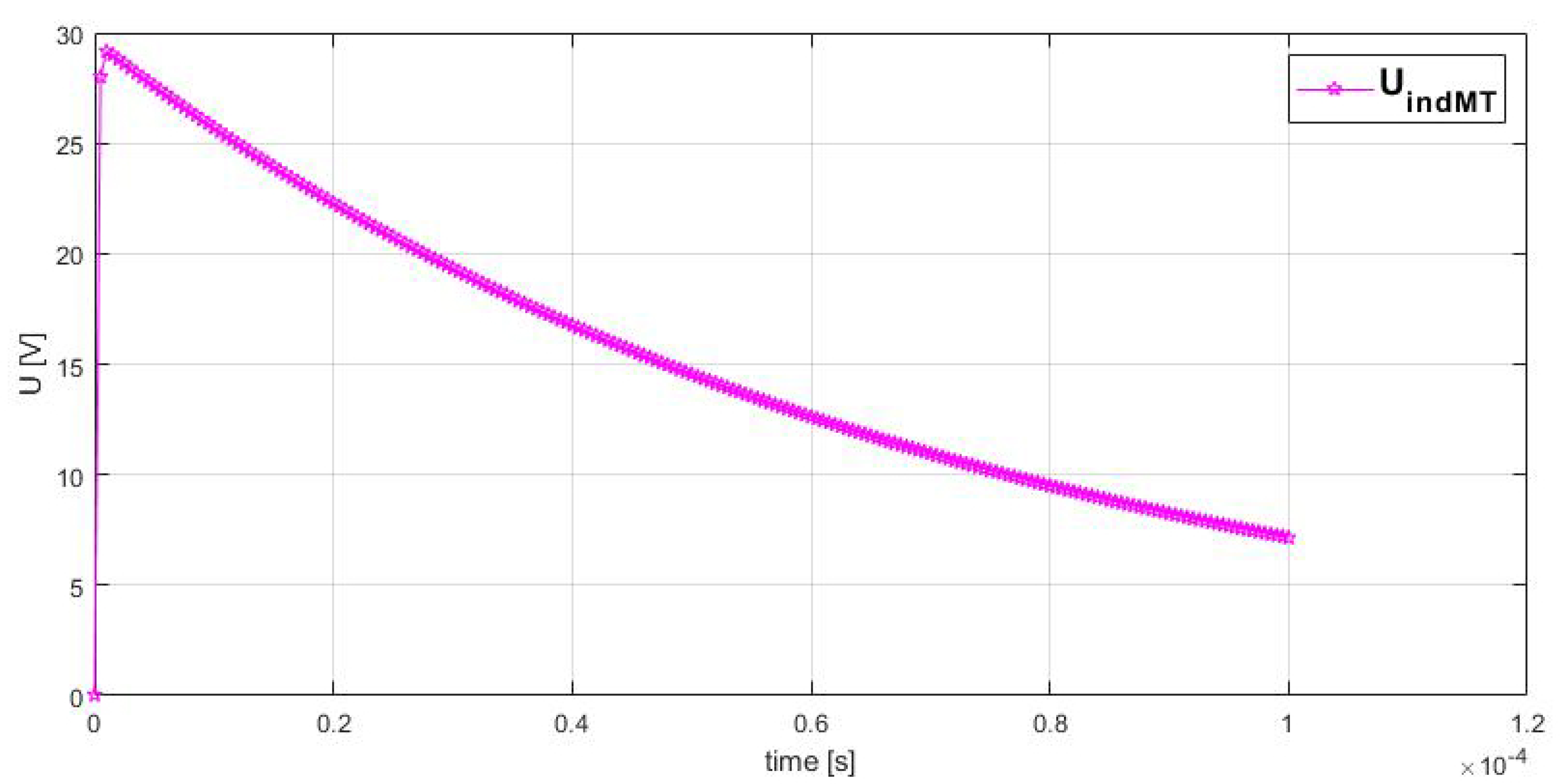
The maximum value of the voltage that was transmitted by electromagnetic induction,
, was 29.154 V (see
Figure 7).
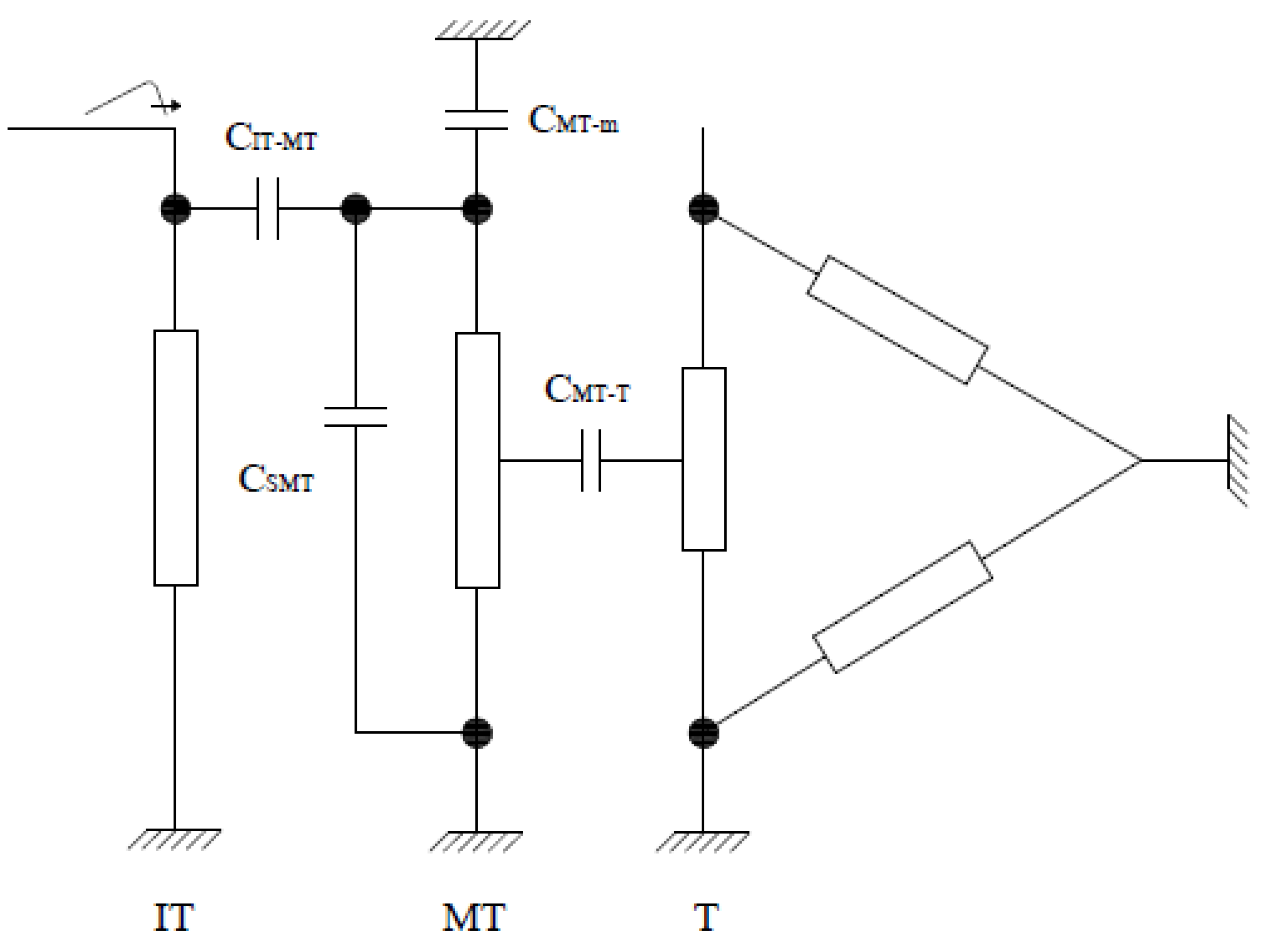
The transmission of the lightning impulse energizing the high-voltage winding to the medium-voltage winding through the existing capacitance chain is explained in the
Figure 8.
The lightning voltage division factor is given by the following relation (42):
where
is the equivalent capacity of the medium-voltage winding to earth (ground).
The equivalent capacity of the medium-voltage winding with respect to earth is determined on the basis of the following relation (43):
The relation describing the time evolution of the oscillating voltage caused by energizing the medium-voltage winding with a pulse wave that has been reduced in amplitude by the factor
is determined by the following relation:
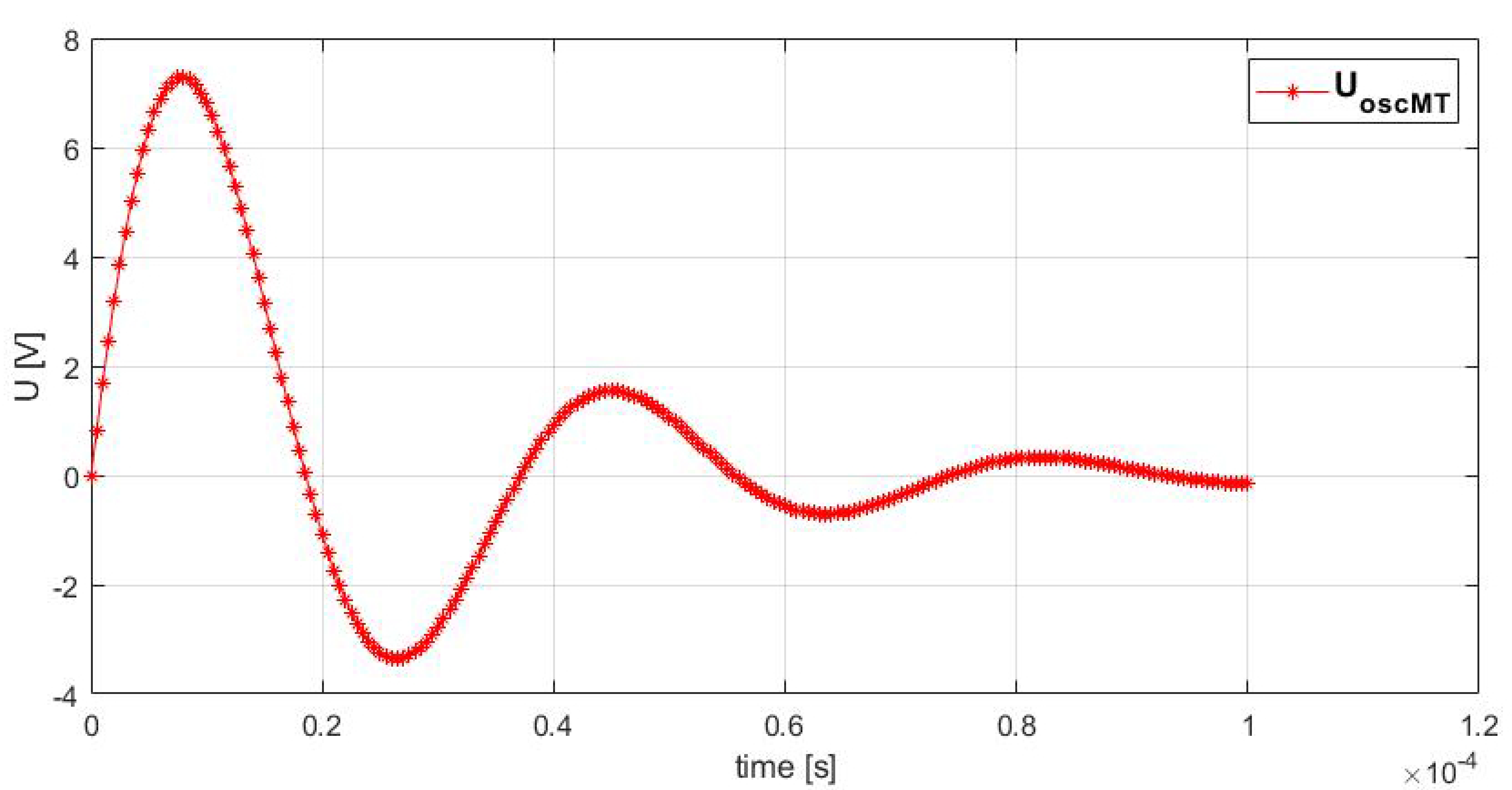
The graphical representation of the oscillating voltage variation as a function of time is given in
Figure 9.
The maximum value of the oscillating voltage caused by energizing the medium-voltage winding, , is 7.2783 V.
The voltage transmitted from the high-voltage winding to the medium-voltage winding is the sum of the inductively and capacitively transmitted voltages (see
Figure 7 and
Figure 9).
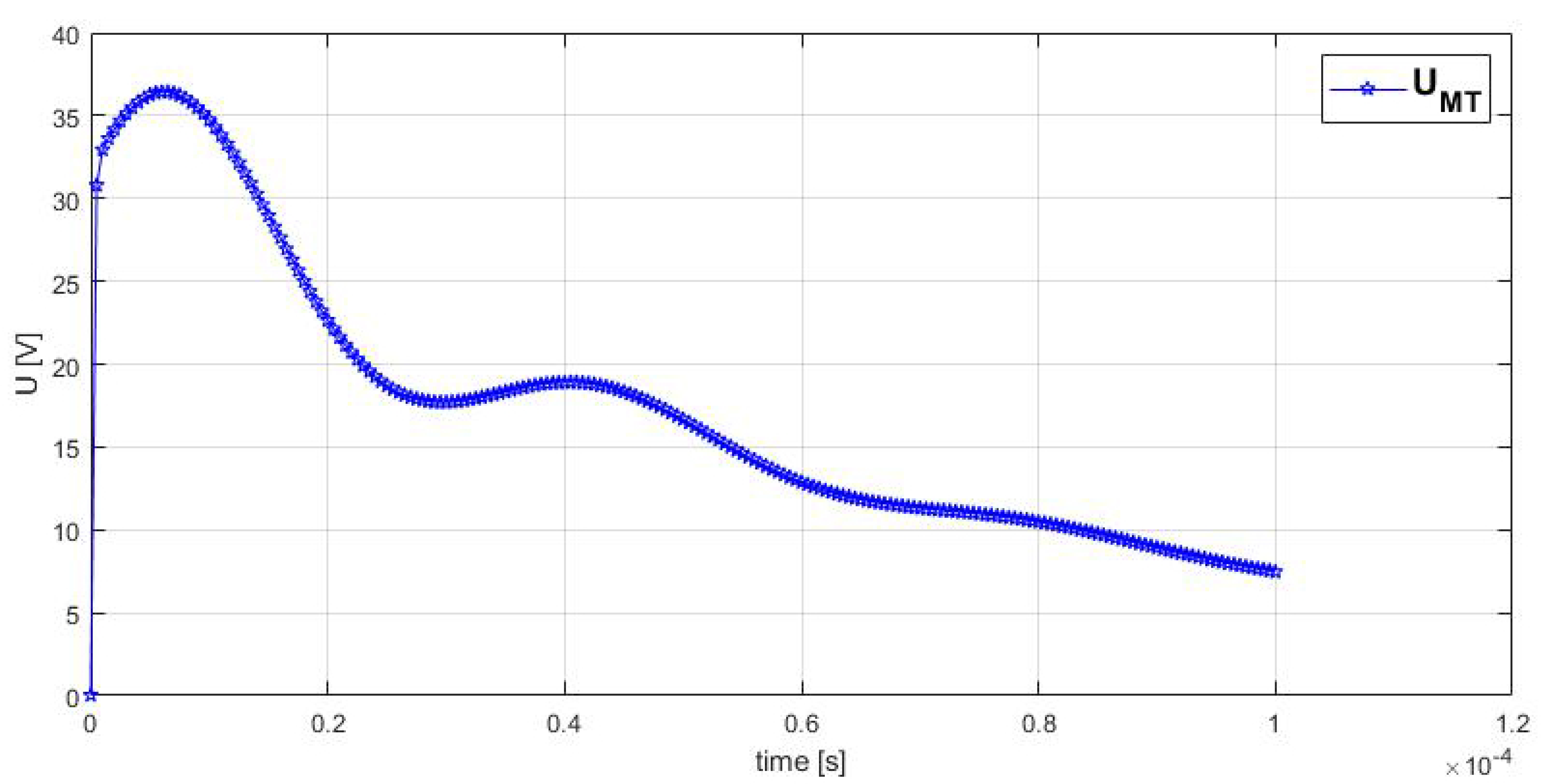
Overvoltage transmitted from high voltage to medium voltage winding, is depicted in
Figure 10.
The maximum value of the overvoltage that is transmitted from the IT winding to the MT winding is the result of the superposition of the inductive and capacitive propagated overvoltages and has a value of 36.4323 V.
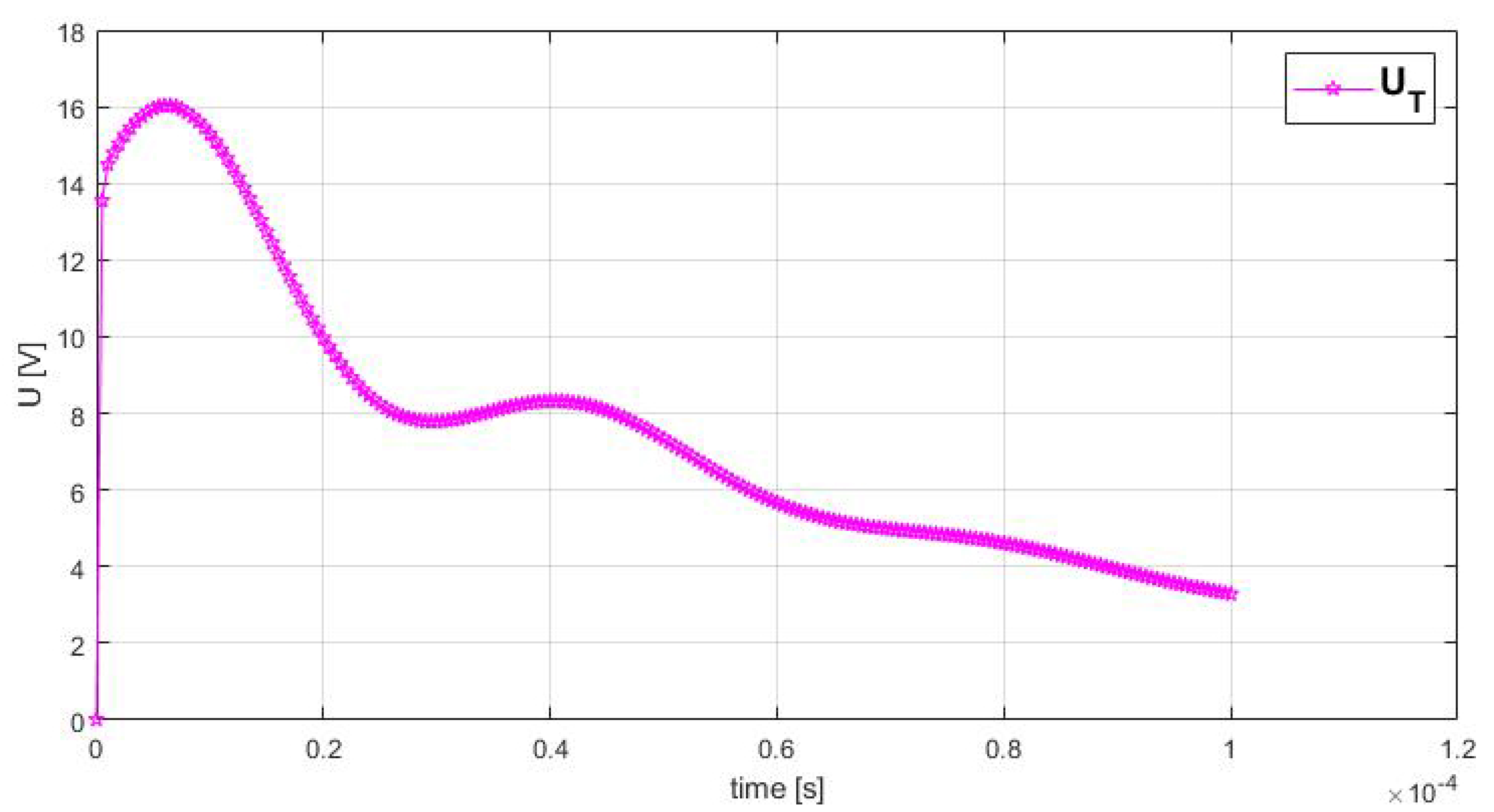
The MT winding behaves as a screen that prevents the capacitive transmission of the voltage from the IT (energized winding) to the T winding. As a result, the transmission of the overvoltage is inductively proportional to the number of turns between the MT and T windings.
The maximum value of the overvoltage that is transmitted to T when IT is energized with lightning impulse was determined using Equation (41) and has a numerical value of 16.0302 V (see
Figure 11).
4. The Test Circuit and Experimental Results
The following equipment and apparatus were used:
A repeated pulse generator, 100 W, 220 V, 50 Hz HAEFELy—Switzerland;
A digital measuring system type TR-AS lOO-12/4, no: 1291, Dr.Straus—Germany.
Test set-up: The low-voltage impulses (1.2/50 µs) were applied between each IT terminal and earth from the repeated pulse generator. When the impulse was applied on an IT terminal, the other IT terminals and their corresponding MT and T terminals were connected to earth by 500 Ω resistances. The neutral terminals were also connected directly to earth during the entire test. The MT and T homolog terminals of the IT terminal on which the voltage was applied were left free (see
Figure 12).
The maximum value recorded between the medium-voltage winding and ground at a 292.4 V pulse was 35.9 V. Compared to the value obtained in the simulation, 36.4323 V, this is relatively close (see
Figure 10 and
Figure 13).
The percentage error between the voltage value that we obtained by modeling and that resulting from the measurement for the medium-voltage winding and ground was 1.46%.
The maximum value of the voltage that is transmitted to the tertiary winding of the transformer at a pulse of 292.4 V is 15.74 V. Compared with the value obtained in the simulation, 16.0302 V, it can be seen that there are small differences between the results (see
Figure 11 and
Figure 13).
The percentage error between the voltage value that we obtained by modeling and that resulting from measurement for the voltage that was transmitted to the tertiary winding was 1.81%.
The difference between the results that we obtained with the proposed method and the experimentally obtained results may be due to the approximations introduced in the mathematical model for the determination of overvoltages, such as the following:
The negation of magnetic core losses and Joule losses;
The variation in the resistance of the conductors of the transformer windings with time, generated by the variation over time in the frequency of the electric field that was produced by the lightning impulse.
Before a pulse is applied, a period of time should be allowed to allow any residual charge to dissipate [
5,
38,
39,
40]; this may influence the value of the measured overvoltages.
5. Conclusions
Lightning overvoltages are a significant threat to the safe operation and reliability of electrical transformers. By understanding the mechanisms by which these phenomena are generated and implementing appropriate protective measures, the risk of damage can be significantly reduced, and a continuous, quality power supply can be ensured.
The maximum value recorded between the medium-voltage winding and ground at a pulse of 292.4 V was 35.9 V. Compared to the value obtained in the simulation, 34.1014 V, this was relatively close. The maximum value of the voltage transmitted to the transformer tertiary winding at a pulse of 292.4 V was 15.74 V. Compared with the value obtained in the simulation, 16.0302 V, it can be seen that there are small differences between the results.
The percentage error between the results obtained by modeling and the results obtained from transformer testing for the MT winding and earth was 1.46%, and for the overvoltage that was transmitted to the T winding, it was 1.81%.
The results obtained by applying the proposed method encourage its use in order to fulfill the needs of the transformer planner/buyer for the following reasons:
It can estimate dielectric stresses in the power transformer windings;
It effectively and correctly identified the maximum value of the overvoltage, thus allowing for optimization in transformer insulation design;
It establishes a correlation between the transformer dielectric performance and that of the protection/signaling equipment in the substation.
The experimental results obtained when measuring the voltages that were transmitted between the transformer windings following a lightning impulse validate the method proposed in this paper.
Author Contributions
Conceptualization, M.-C.N. and I.-D.N.; methodology, M.-C.N., L.-A.D. and P.-M.M.; software, I.-D.N. and M.-Ş.N.; validation, L.-A.D. and M.-Ş.N.; formal analysis, M.-C.N. and P.-M.M.; investigation, M.-C.N.; resources, M.-C.N.; data curation, I.-D.N.; writing—original draft preparation, M.-C.N.; writing—review and editing, M.-C.N., L.-A.D. and P.-M.M.; visualization, I.-D.N. and M.-Ş.N.; supervision, L.-A.D. and P.-M.M.; project administration, M.-C.N.; funding acquisition, I.-D.N. All authors have read and agreed to the published version of the manuscript.
Funding
This research was funded by University of Craiova.
Institutional Review Board Statement
Not applicable.
Informed Consent Statement
Not applicable.
Data Availability Statement
The original contributions presented in the study are included in the article.
Acknowledgments
This work was developed as part of a research grant from the Academy of Romanian Sciences with the following project title: Monitoring and analysis of electrical parameters obtained with a mobile data acquisition system, using advanced processing technologies—Wavelet transforms.
Conflicts of Interest
The authors declare no conflicts of interest.
References
- Kulkarni, S.V.; Khaparde, S.A. Transformer Engineering: Design and Practice; Marcel Dekker Inc.: New York, NY, USA, 2004; p. 478. [Google Scholar]
- Kuffel, E.; Zaengl, W.S.; Kuffel, J. High Voltage Engineering: Fundamentals, 2nd ed.; Butterworth-Heinemann: Oxford, UK, 2000; p. 559. [Google Scholar]
- Khalifa, M. High-Voltage Engineering—Theory and Practice; Marcel Dekker Inc.: New York, NY, USA, 1990; p. 524. [Google Scholar]
- IEC 60076-1; Power Transformer. Part 1: General, 3rd ed. International Electrotechnical Commission (IEC): Geneva, Switzerland, 2011.
- IEC 60076-3; Power Transformer. Part 3: Insulation Level, Dielectric Tests and External Clearances in Air, 3rd ed. International Electrotechnical Commission (IEC): Geneva, Switzerland, 2013.
- IEC 60060-1; High-Voltage Test Techniques. Part 1: General Definitions and Test Requirements, 3rd ed. International Electrotechnical Commission (IEC): Geneva, Switzerland, 2010.
- IEC 60060-2:2010; High-Voltage Test Techniques—Part 2: Measuring Systems, 3rd ed. International Electrotechnical Commission (IEC): Geneva, Switzerland, 2010.
- IEC 60060-3; High-Voltage Test Techniques—Part 3: Definitions and Requirements for On-Site Testing, 1st ed. International Electrotechnical Commission (IEC): Geneva, Switzerland, 2006.
- Sălceanu, C.-E.; Dobrea, C.; Ocoleanu, D.; Nicola, M.; Iovan, D.; Nițu, M.-C. Experimental Study of the Dynamic Short-Circuit Withstand Capability of an 8400 kVA Power Transformer Specially Designed for Photovoltaic Applications. Machines 2023, 11, 969. [Google Scholar] [CrossRef]
- Adamczyk, B.; Pająk, P.; Florkowski, M. Comparison of Initial Voltage Distributions in Layer and Disc Type Power Transformer Windings. IEEE Trans. Dielectr. Electr. Insul. 2025, 32, 73–82. [Google Scholar] [CrossRef]
- Cakil, T.; Carlak, H.F.; Ozen, S. The Indirect Effect of Lightning Electromagnetic Pulses on Electrostatic, Electromagnetic Fields and Induced Voltages in Overhead Energy Transmission Lines. Appl. Sci. 2024, 14, 3090. [Google Scholar] [CrossRef]
- Staruhina, E.A.; Syutkin, A.V.; Evdokunin, G.A. Investigation of Ferroresonance Processes Leading to Thermal Damage of Cast-Insulated Transformers. In Proceedings of the International Ural Conference on Electrical Power Engineering (UralCon), Magnitogorsk, Russia, 23–25 September 2022; pp. 213–217. [Google Scholar] [CrossRef]
- Yu, W.; Ye, Z.; Gou, J.; Tan, K.; Cai, J.; Luo, J. Effects of Iron Core Materials on a Single-phase Power Transformer during Out-of-Phase Synchronisation in MicroGrid. In Proceedings of the IEEE 4th Conference on Energy Internet and Energy System Integration (EI2), Wuhan, China, 30 October–1 November 2020; pp. 1593–1598. [Google Scholar] [CrossRef]
- De Carvalho Rocha, L.; Trezza Borges, T.; Las Casas, F. Overvoltages in Medium Voltage Industrial Systems Associated with Switching High Voltage Transformers Connected Through Insulated Cables. In Proceedings of the IEEE IAS Petroleum and Chemical Industry Technical Conference (PCIC), Orlando, FL, USA, 16–19 September 2024; pp. 1–8. [Google Scholar] [CrossRef]
- Florkowski, M.; Furgał, J.; Kuniewski, M. Propagation of Overvoltages in the Form of Impulse, Chopped and Oscillating Waveforms in Transformer Windings—Time and Frequency Domain Approach. Energies 2020, 13, 304. [Google Scholar] [CrossRef]
- Dworakowski, P.; Wilk, A.; Michna, M.; Fouineau, A.; Guillet, M. Lagrangian Model of an Isolated DC-DC Converter With a 3-Phase Medium Frequency Transformer Accounting Magnetic Cross Saturation. IEEE Trans. Power Deliv. 2021, 36, 880–889. [Google Scholar] [CrossRef]
- Beňová, M.; Dobrucký, B.; Šedo, J.; Praženica, M.; Koňarik, R.; Šimko, J.; Kuchař, M. A Novel Approach to Transient Fourier Analysis for Electrical Engineering Applications. Appl. Sci. 2024, 14, 9888. [Google Scholar] [CrossRef]
- Trkulja, B.; Drandić, A.; Milardić, V.; Žiger, I. Evaluation of Methodology for Lightning Impulse Voltage Distribution over High-Voltage Windings of Inductive Voltage Transformers. Energies 2021, 14, 5144. [Google Scholar] [CrossRef]
- Tuethong, P.; Yutthagowith, P.; Kunakorn, A. Effective Simulation Approach for Lightning Impulse Voltage Tests of Reactor and Transformer Windings. Energies 2020, 13, 5399. [Google Scholar] [CrossRef]
- Nicolae, P.-M.T.; Nicolae, I.-D.V.D.; Nițu, M.-C.; Nicolae, M.-S.P.M. Analysis and Experiments Concerning Surges Transferred Between Power Transformer Windings Due to Lightning Impulse. IEEE Trans. Electromagn. Compat. 2023, 65, 1476–1483. [Google Scholar] [CrossRef]
- Avendaño, A.; Mork, B.A.; Ishchenko, D.; Gonzalez, F. Advanced Leakage Inductance Model for Transformer Transient Simulation. In Proceedings of the IEEE Power & Energy Society General Meeting (PESGM), Portland, OR, USA, 5–10 August 2018; pp. 1–5. [Google Scholar] [CrossRef]
- Hu, R.; Zhang, Z.; Wang, S.; Lu, Y.; Liu, L.; Zhu, S.; Peng, Z. Electric Field Optimization of Cast Resin Dry-Type Transformer under Lightning Impulse. In Proceedings of the IEEE Conference on Electrical Insulation and Dielectric Phenomena (CEIDP), Richland, WA, USA, 20–23 October 2019; pp. 556–559. [Google Scholar] [CrossRef]
- Gupta, S.C.; Singh, B.P. Determination of the impulse voltage distribution in windings of large power transformers. Electr. Power Syst. Res. 1992, 25, 183–189. [Google Scholar] [CrossRef]
- Nițu, M.-C.; Nicola, M.; Nicola, C.-I.; Aciu, A.-M.; Ocoleanu, D.; Sălceanu, C.E. Overvoltage Produced by Lightning Impulse in High Power Transformers—Parameters that Influence their Transmission. In Proceedings of the International Conference on Applied and Theoretical Electricity (ICATE), Craiova, Romania, 27–29 May 2021; pp. 1–6. [Google Scholar] [CrossRef]
- Zirka, S.E.; Moroz, Y.I.; Rahimpour, E. Towards a transformer transient model as a lumped-distributed parameter system. COMPEL-Int. J. Comp. Math. Electr. Electron. Eng. 2017, 36, 741–750. [Google Scholar] [CrossRef]
- Fegerstad, P.I.; Henriksen, T. Inductance for the Calculation of Transient Oscillation in Transformers. IEEE Trans. Power Appar. Syst. 1974, PAS-93, 510–517. [Google Scholar] [CrossRef]
- Arturi, C.M. Transient simulation and analysis of a three-phase five-limb step-up transformer following an out-of-phase synchronization. IEEE Trans. Power Deliv. 1991, 6, 196–207. [Google Scholar] [CrossRef]
- Cristina, S.; D’Amore, M.; Salermo, M. Digital Simulator Transformer Windings Subject to impulse Voltage. IEEE Proc. 1982, 129, 172–176. [Google Scholar] [CrossRef]
- Chadwik, A.T.; Ferguson, J.M.; Ryder, D.H.; Stearn, G.F. Design of Power Transformers to Withstand Surges due to Lightning, with Secial Referance to a New Type of Winding. IEEE Proc. 1950, 97, 737–750. [Google Scholar]
- Chowdhuri, P. Calculation of Serie Capacitance for Transient Analysis of Windings. IEEE Trans. Power Deliv. 1987, PWRD-2, 133–139. [Google Scholar] [CrossRef]
- Robins, L. Transformer Reactances Calculations with Digital Computer. AIEE Trans. 1956, 75, 261–267. [Google Scholar] [CrossRef]
- Chen, H.-T.; Lin, J.-Y. Application of the Laplace transform to nonlinear transient problems. Appl. Math. Model. 1991, 15, 144–151. [Google Scholar] [CrossRef]
- Kim, H.J. The solution of Euler-Cauchy equation expressed by differential operator using Laplace transform. Int. J. Pure Appl. Math. 2013, 84, 345–351. [Google Scholar] [CrossRef][Green Version]
- Kazem, S. Exact Solution of Some Linear Fractional Differential Equations by Laplace Transform. Int. J. Nonlin. Sci. 2013, 16, 3–11. [Google Scholar]
- Korn, G.; Korn, T. Mathematical Handbook for Scientists and Engineers; Mc. Graw-Hill: New York, NY, USA, 1961; p. 720. [Google Scholar]
- Yang, Y.; Wang, Q.; Gao, C.; Pu, J.; Zhang, X.; Li, J. Study of Comparison of Voltage Distribution in Transformer under Different Lightning Impulse Voltages. In Proceedings of the 2020 IEEE International Conference on High Voltage Engineering and Application (ICHVE), Beijing, China, 6–10 September 2020; pp. 1–4. [Google Scholar] [CrossRef]
- Hans-Petter Halvorsen—LabVIEW MathScript. Available online: https://www.halvorsen.blog/documents/teaching/courses/labview_automation/resources/LabVIEW%20MathScript%20Module.pdf (accessed on 14 February 2025).
- Yutthagowith, P. Non-Iterative Technique for Determination of Full Lightning Impulse Voltage Parameters. Energies 2022, 15, 4199. [Google Scholar] [CrossRef]
- Arı, İ.; Mamiş, M.S. Voltage Distribution on Transformer Windings Subjected to Lightning Strike Using State-Space Method. Appl. Sci. 2025, 15, 1569. [Google Scholar] [CrossRef]
- IEEE Std C57.98-2011; IEEE Guide for Transformer Impulse Tests—Redline. (Revision of IEEE Std C57.98-1993)—Redline. IEEE: Piscataway, NJ, USA, 2012; pp. 1–146ISBN 978-0-7381-7127-2.
| Disclaimer/Publisher’s Note: The statements, opinions and data contained in all publications are solely those of the individual author(s) and contributor(s) and not of MDPI and/or the editor(s). MDPI and/or the editor(s) disclaim responsibility for any injury to people or property resulting from any ideas, methods, instructions or products referred to in the content. |
© 2025 by the authors. Licensee MDPI, Basel, Switzerland. This article is an open access article distributed under the terms and conditions of the Creative Commons Attribution (CC BY) license (https://creativecommons.org/licenses/by/4.0/).

