1. Introduction
Hydrogen is regarded as a key fuel for the future, with applications ranging from powering buildings and vehicles to serving as rocket fuel. As a clean energy carrier, it supports renewable energy sources and can be utilized in combustion engines or, more efficiently, in fuel cells to generate electricity for electric motors [
1,
2,
3,
4,
5,
6,
7]. Additionally, hydrogen functions as an energy storage medium, allowing surplus electricity to be stored via electrolysis during off-peak hours, thereby minimizing energy waste [
2,
3,
8,
9]. Recent technological advancements have improved hydrogen’s feasibility, positioning it as a potential primary energy carrier in a sustainable future [
3,
4,
8]. However, challenges persist in hydrogen production and storage, as different methods vary in cost and environmental impact.
HHO gas, also known as Brown’s gas or oxyhydrogen gas, is a mixture of hydrogen (H
2) and oxygen (O
2) in a 2:1 ratio, mirroring the composition of water (H
2O). It is generated through water electrolysis, a process in which an electric current separates water into its constituent hydrogen and oxygen gases. Due to its higher flammability compared to diesel fuel, HHO gas can enhance combustion efficiency in diesel engines. The introduction of hydrogen increases the fuel’s hydrogen-to-carbon (H/C) ratio, thereby reducing carbon-based emissions. Additionally, hydrogen exhibits an exceptionally high diffusion rate in air, which helps mitigate diesel fuel injection inhomogeneity and facilitates a more uniform fuel–air mixture [
1].
According to Najafi et al. [
1], the use of HHO gas in combination with biodiesel fuel in diesel engines has shown promising results. Studies consistently indicate that incorporating HHO gas enhances braking power, braking torque, and braking thermal efficiency while reducing brake-specific fuel consumption. Additionally, most researchers have observed that HHO gas lowers emissions of carbon monoxide (CO), unburned hydrocarbons (UHC), and particulate matter (PM), although it leads to an increase in nitrogen oxides (NOx) and carbon dioxide (CO
2) emissions [
1]. Therefore, integrating HHO gas into diesel engines presents a viable strategy for improving performance and reducing emissions in dual-fuel diesel engines without requiring modifications to the engine structure. As an emerging and sustainable energy source, HHO gas holds potential for enhancing energy security both now and in the future [
1].
Water electrolysis is inherently slow, resulting in an overall electrolyzer efficiency of less than 40%. To make gas production more cost-effective and viable for a hydrogen-based economy, advancements are required to enhance system kinetics and reduce energy consumption [
1,
4,
10,
11]. Research efforts focus on developing cost-effective electrode materials, minimizing the electrode gap, and improving overall system efficiency [
2,
4,
5,
10,
11,
12,
13].
The influence of electrode materials on electrolyzer cost and efficiency remains underexplored [
2,
4,
10,
12,
13]. Studies show that 316L stainless steel outperforms carbon steel in both hydrogen production and efficiency [
12]. Nickel and stainless steel electrodes offer a cost-effective solution with favorable electrochemical properties. Additionally, polished electrodes generate gas at a higher rate than unpolished ones, as they have fewer oxide layers that would otherwise increase resistance and reduce active reaction sites, as highlighted by Symes et al. [
2].
Aluminum alloys, prone to oxidation, can serve as high-performing anodes for auxiliary hydrogen production systems in electrolyzers [
10]. Reda et al. [
13] examined various aluminum alloy compositions and temper conditions as electrodes in an electrolyzer. Their study identified 6061-T0 Al alloy as the most efficient, offering the highest hydrogen flow rate, lower energy consumption, and superior process efficiency at a reasonable cost. In contrast, 6061-T6 and 7075-T6 Al alloys performed the worst, exhibiting low hydrogen flow rates, high energy consumption, and poor efficiency. Meanwhile, 1050-T0, 5052-T0, 7075-T0, and 7075-T7 Al alloys demonstrated moderate performance, making them viable alternatives for hydrogen production.
Ridhwan et al. [
14] examined the effects of KOH electrolyte concentration and electrode surface texture on HHO generator performance. Their findings revealed that increasing KOH concentration and modifying the electrode surface texture enhanced performance by expanding the electrode surface area.
Similarly, Reda et al. [
13] reported that elevating the electrolysis temperature had the most significant impact on improving hydrogen production efficiency, followed by increasing the electrode surface area. In contrast, altering the electrode material had the least effect on efficiency enhancement.
Okonkwo et al. [
5] examined the effect of electrode spacing on hydrogen production. Their study found that reducing the distance between immersed electrodes enhanced the electrochemical reaction rate, increased hydrogen production, and improved efficiency.
Although extensive research exists on water electrolysis, limited studies explore the relationship between electrode material, manufacturing processes, and efficiency. Therefore, a more comprehensive investigation is required to bridge this knowledge gap and better understand the influence of material processing and structure on gas production efficiency.
Efficient hydrogen storage remains a critical challenge in advancing the hydrogen economy. Hydrogen can be stored in three primary forms: compressed gaseous hydrogen (GH
2), liquid hydrogen (LH
2), and cryo-compressed hydrogen (CcH
2), each with distinct characteristics [
3,
13,
15,
16]. Compressed Gaseous Hydrogen (GH
2): Stored at room temperature under extremely high pressures (up to 700 bar). While lightweight, it requires large storage volumes and has low energy density, with up to 10% energy loss during compression. Liquid Hydrogen (LH
2): Stored at cryogenic temperatures (−240 to −253 °C) and low pressures (~10 bar). It offers higher energy density but demands strict insulation and consumes up to 40% of energy during liquefaction. Cryo-compressed Hydrogen (CcH
2): Stored at cryogenic temperatures (−196 to −240 °C) and moderate pressures (150–350 bar). This method combines the advantages of GH
2 and LH
2, offering greater efficiency and flexibility [
6].
Hydrogen can be stored in four types of pressure vessels (PVs). Type I: Fully metallic. Type II: A metallic liner reinforced with a fiber-resin composite along the hoop section. Type III: A metallic liner fully overwrapped with a fiber-resin composite. Type IV: A polymer liner entirely encased in composite material. While composite PVs offer superior performance, their high cost limits widespread adoption [
3,
6,
13,
15,
16]. The design of PVs must consider operating conditions, lifespan, external loads, and potential failure modes when selecting materials [
15]. Choosing the optimal storage method requires balancing cost and technical performance based on the specific application.
Under high pressure, hydrogen adsorbs and dissolves on material surfaces, where atomic hydrogen diffuses into the material and interacts with lattice defects, leading to hydrogen embrittlement (HE)—a phenomenon that reduces ductility and toughness [
3,
6]. HE primarily affects metallic materials used in storage tanks under hydrogen exposure, potentially causing premature cracking and loss of mechanical properties due to stress corrosion cracking or hydrogen-induced cracking [
6,
16].
Both industry and academia have extensively studied HE mechanisms, alloy manufacturing, component assembly, and mechanical testing to improve material performance [
3,
15,
16]. The safety of hydrogen storage systems depends on selecting suitable materials for critical components, including fittings, valves, connectors, container walls, and pipelines [
3].
Type I pressure vessels, as well as the metallic components of other types, such as liners and bosses, are commonly made from stainless steel, high Cr-Ni-Mo alloyed steels, or aluminum alloys [
6,
13,
15]. Unlike body-centered cubic (BCC) structures, face-centered cubic (FCC) materials exhibit minimal hydrogen diffusion due to their low diffusion coefficient at ambient and low temperatures [
13,
16].
Austenitic stainless steel is widely used for hydrogen storage and transportation due to its high resistance to hydrogen embrittlement, attributed to low hydrogen diffusivity and high solubility at room temperature [
7,
9,
16]. The chemical composition, manufacturing method, and heat treatment of stainless steel alloys significantly influence both their mechanical properties and hydrogen embrittlement behavior [
16,
17,
18,
19].
Type I pressure vessels, as well as the liners for Type II and III vessels, are typically manufactured using a combination of rolling, welding, casting, heat treatment, and drilling [
7,
15,
17]. While these methods are well-established and cost-effective, they impose geometric limitations [
7,
15,
17]. In industrial applications, Type I pressure vessels made of 316L stainless steel are commonly used for hydrogen storage at pressures ranging from 20 to 30 MPa [
6].
Additive manufacturing (AM) enables the fabrication of intricate 3D geometries, allowing for the production of highly functional components with reduced lead time and lower costs. This efficiency has increased interest in AM for manufacturing specialized metallic parts designed to withstand harsh operating conditions, such as those encountered in hydrogen technology [
7,
17,
18,
19,
20].
Laser powder bed fusion (LPBF) is one of the most widely used AM techniques for metal fabrication [
7,
9,
17,
18,
19,
20,
21]. The LPBF process is characterized by high cooling rates during solidification and complex thermal gradients [
18]. As a result, additively manufactured 316L stainless steel typically exhibits higher strength due to the fine microstructure formed during processing [
16].
Ringel et al. [
17] used AM to fabricate a 316L stainless steel pressure vessel and reported failure between 67 and 70 MPa. Similarly, Wang et al. [
21] highlighted the widespread use of AM 316L stainless steel in cryogenic applications, citing its excellent corrosion resistance and extremely low ductile-to-brittle transition temperature.
The hydrogen embrittlement (HE) sensitivity of additively manufactured (AM) 316L stainless steel is expected to differ from that of conventionally manufactured 316L. Understanding the fabrication process and structural characteristics of hydrogen storage materials is essential for comprehending the HE mechanisms in storage tanks [
3].
Current research on the HE behavior of AM 316L stainless steel has primarily focused on microstructural analysis and embrittlement mechanisms across various AM metals. However, studies remain limited, particularly in evaluating the impact of post-processing heat treatments (PPHT) on the hydrogen embrittlement resistance of AM materials. This gap highlights the need for further investigation into the correlation between AM processing conditions, heat treatment, and HE performance.
Miller et al. [
22] investigated the hydrogen embrittlement (HE) behavior of additively manufactured (AM) 316L stainless steel, reporting lower ductility and greater HE susceptibility compared to thermomechanically processed 316L stainless steel. They attributed this increased HE susceptibility to factors such as high residual stress, greater porosity, and faster hydrogen diffusion in AM 316L stainless steel.
Similarly, Bertsch et al. [
23] found that the HE susceptibility of AM 316L stainless steel is strongly influenced by its initial microstructure, particularly the morphology and density of dislocations. However, they noted that deformation twinning, dendritic segregation, and precipitates had a minimal impact on HE behavior. Additionally, their study suggested that selective laser melted (SLM) 316L stainless steel could be a viable option for hydrogen applications, owing to its high yield strength and resistance to HE.
Álvarez et al. [
20] investigated the impact of post-build processing—including annealing, hot isostatic pressing (HIP), and HIP followed by 30% cold working—on the hydrogen embrittlement (HE) behavior of additively manufactured (AM) 316L stainless steel produced via laser powder bed fusion (LPBF). The study assessed HE susceptibility through uniaxial tensile testing at both room temperature and −50 °C. Their findings revealed that the AM material exhibits directional sensitivity in both hydrogen-charged and uncharged conditions. Among the processing conditions, HIP-treated specimens demonstrated the highest resistance to HE.
Luo et al. [
18] investigated how variations in processing parameters during the LPBF process and subsequent heat treatments influence grain boundary evolution in 316L stainless steel. Their findings indicated that differences in recrystallization behavior, driven by additive manufacturing conditions, are primarily due to changes in dislocation density and chemical inhomogeneity within the as-solidified microstructure.
Zhou et al. [
19] found that distinctive microstructural features—including cellular structures, elevated dislocation density, melt pool boundaries, and deformation twins—play a crucial role in influencing martensitic transformation, as well as hydrogen diffusion and transport, thereby impacting the material’s susceptibility to hydrogen embrittlement.
With the growing demand for hydrogen applications, additive manufacturing (AM) technologies offer enhanced design flexibility and customization advantages [
7,
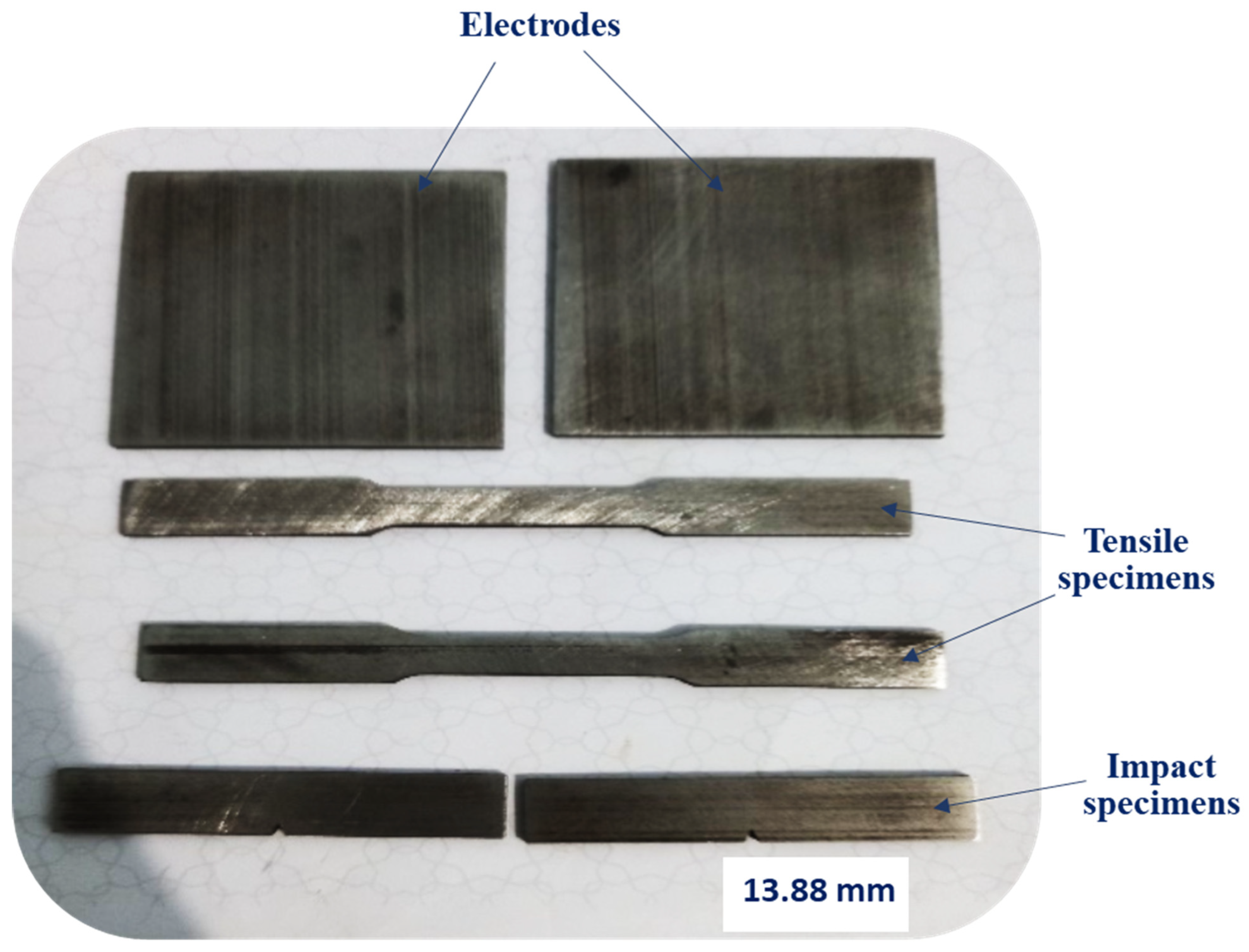
19]. This study investigates the performance of AM 316L stainless steel alloys, fabricated using selective laser melting (SLM), for HHO gas production and hydrogen storage applications. The research compares the performance of as-built and post-heat-treated AM materials with that of as-rolled stainless steel, evaluating their effectiveness as electrodes in an electrolyzer operating at 60 °C under varying currents. Additionally, the alloys were tested for hydrogen embrittlement (HE) through tensile and Charpy impact toughness tests before and after hydrogen charging. To simulate hydrogen storage conditions, mechanical testing was conducted at room temperature (to simulate gaseous hydrogen storage) and in liquid nitrogen (to simulate liquid and cryo-compressed hydrogen storage). The fracture surfaces of different material conditions were analyzed using scanning electron microscopy (SEM). Ultimately, the study identifies the most suitable alloy for both electrode and hydrogen storage applications.
3. Results and Discussion
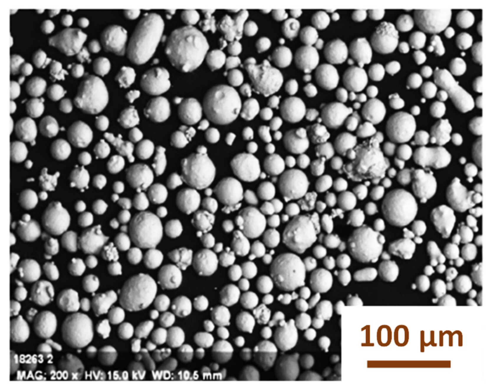
Stainless steel of the 316L type with an FCC crystal structure has different microstructural attributes based on the production conditions. The elongated austenitic phase with a high dislocation density is the main attribute of the as-rolled microstructure, and if the cold rolling was extensive, some strain-induced martensite might have occurred.
High dislocation densities, cellular grain structures with solute segregation along cell walls, and high residual stresses from thermal contraction are some of the features of non-equilibrium microstructures produced by extremely high thermal gradients and fast cooling rates in laser powder bed fusion (LPBF) and other AM processes. Internal energy is stored as a result of these traits. Depending on the treatment parameters, post-processing heat treatment of the as-built condition caused microstructure alterations.
Compared to the as-built microstructure, annealing at 800 °C produces slightly coarse cellular austenitic grains. Since 800 °C is lower than the delta-ferrite dissolution or carbide precipitation temperatures for 316L, no phase transformation takes place. The material starts the recovery mechanism to lower its internal energy at this temperature. Subgrains are created when dislocations reorganize into lower-energy structures. This removes residual stress and lowers the dislocation density.
However, because of the recrystallization process, holding at 1050 °C produces equiaxed austenitic grains with a decreased dislocation density and little remaining AM substructure.
It is worthwhile to mention that achieving these microstructural characteristics typically requires a holding period of at least one hour at the treatment temperature. To avoid the complete recrystallization process and preserve some of the characteristics of the as-built characteristics, the holding time was limited, in the current investigation, to 20 min for both treatments and followed the holding at 1050 °C by water quenching. This prevents the strength loss brought on by complete recrystallization.
Since the impact of the current processing conditions was thoroughly examined in earlier research [
9,
26,
27,
28], the current study concentrated on how these conditions affected the materials’ functional performance.
3.1. 316L Stainless Steel Electrodes for Oxyhydrogen Gas Production
3.1.1. HHO Gas Flow Rate
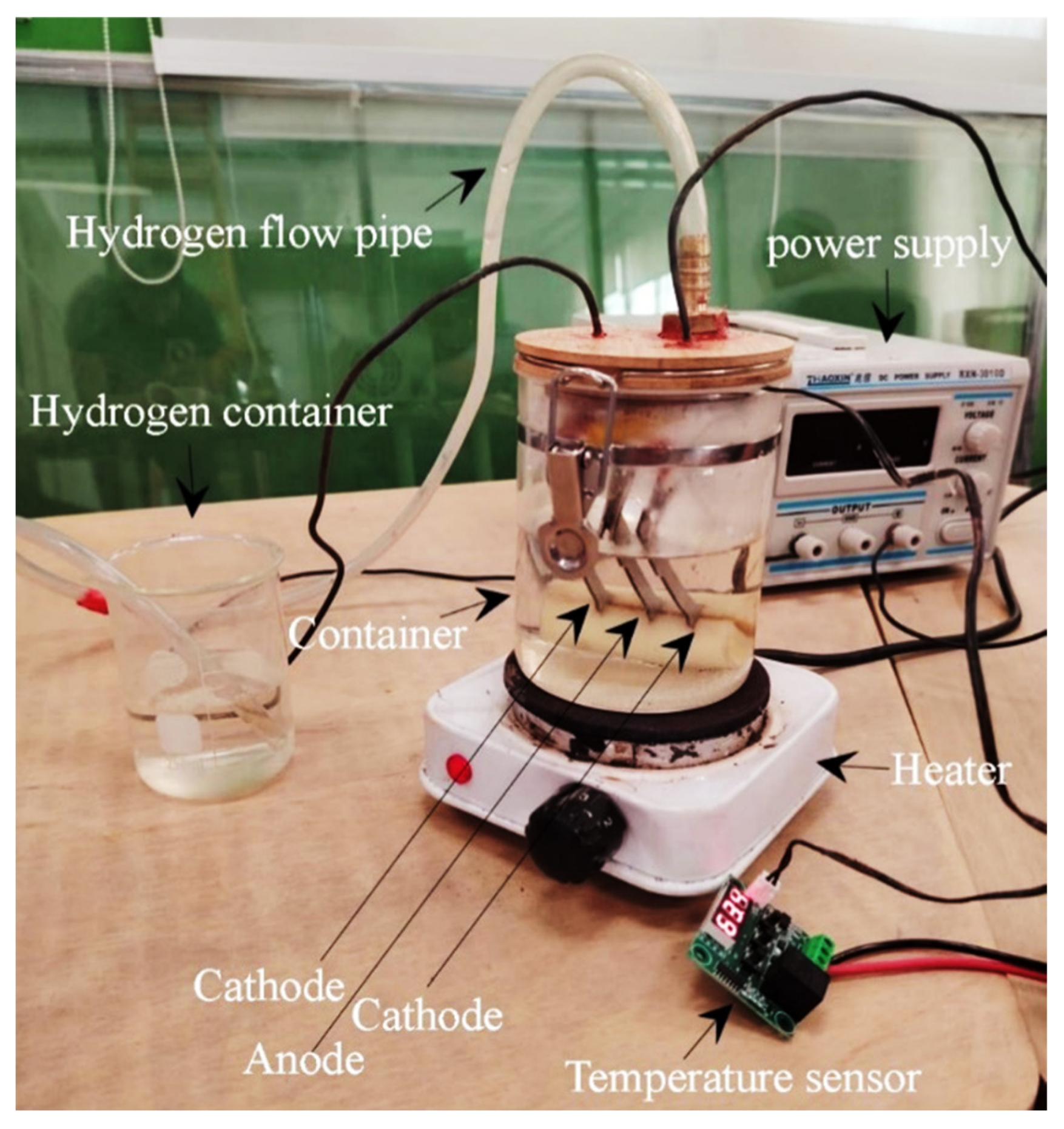
Reducing the electrode spacing and increasing the operating temperature can enhance energy efficiency in water electrolysis. Elevated temperatures improve reaction kinetics by altering the physicochemical properties of water. Specifically, heating decreases water’s dielectric constant, surface tension, and viscosity while increasing the concentration of OH
− and H
+ ions. Additionally, as temperature rises, the voltage required to overcome the Helmholtz energy barrier decreases, thereby lowering the electrical potential necessary for hydrogen gas production, as previously reported [
4,
10].
Based on these principles, a 15 mm electrode spacing and an operating temperature of 80 °C were selected for the current electrolyzer setup to optimize HHO gas production.
In this study, HHO gas flow rate measurements were conducted 10 min after power activation, in 5 min of water electrolysis at 80 °C and at constant currents of 6A, 7A, and 8A.
Figure 6 presents the HHO gas production rates (mL) at different current levels using various electrode materials.
Results indicate that increasing the current from 6A to 8A enhances HHO gas production across all electrode types. This is attributed to the higher current providing a greater number of electrons available for electrochemical reactions, thereby increasing the overall reaction rate and improving hydrogen generation efficiency.
At 6A, the as-rolled electrode exhibited the lowest HHO gas flow rate at 89 mL, followed by the as-built electrode at 110 mL. The HT1 electrode produced 132 mL, while the HT2 electrode generated 135 mL of HHO gas.
At 7A, HHO production increased across all electrode conditions. The as-rolled electrode produced 120 mL, the as-built specimen generated 137 mL, the HT1 electrode yielded 160 mL, and the HT2 electrode produced 174 mL.
At 8A, this trend continued, with the as-rolled electrode producing 138 mL, the as-built electrode generating 170 mL, the HT1 electrode yielding 210 mL, and the HT2 electrode generating 205 mL of HHO gas.
The variations in HHO production rates can be attributed to differences in material microstructure. The as-rolled electrode, serving as the baseline material, exhibited lower HHO production rates due to its fewer catalytic active sites and a less favorable microstructure for electrolysis.
In contrast, the AM electrodes demonstrated higher HHO production rates compared to the as-rolled electrode, suggesting that the additive manufacturing process introduces structural modifications that enhance catalytic activity. The 3D printing process can generate a surface with increased defects and higher roughness, which in turn provides more catalytically active sites, thereby improving the efficiency of the electrolysis process.
Post-processing heat treatment (PPHT) plays a crucial role in reducing grain boundary defects and increasing the material’s uniformity. The uniform grain structure enhances electrical conductivity and reduces resistance, thereby improving HHO production rates. HT1 (held at 800 °C for 20 min, air-cooled) likely reduces residual stresses from the 3D printing process and improves microstructural uniformity, leading to better electrochemical performance. HT2 (held at 1050 °C for 20 min, water-quenched) further enhances the microstructure and surface characteristics, optimizing both mechanical properties and catalytic activity.
The improvement in HHO production at higher currents is more pronounced in post-heat-treated electrodes, indicating that an optimized microstructure and an increased active surface area significantly enhance catalytic efficiency. The HT2 electrodes exhibited the highest HHO production rates, suggesting an optimal balance between mechanical integrity and catalytic performance.
Figure 7 presents the output voltages at different currents using various electrode materials. As shown, the voltage increases with current, ranging from 3.5 to 4.8 volts. These results indicate that PPHT electrodes consume the least power across all operating currents compared to the other electrode materials, demonstrating their improved electrochemical efficiency.
3.1.2. HHO Gas Production Efficiency
Increasing an electrolyzer’s gas generation efficiency has a number of important technical and financial effects. Greater efficiency translates into more HHO gas being produced for the same electrical energy, or, to put it another way, less energy being used by the electrolyzer. As a result, the process becomes more cost-effective and sustainable by lowering the energy cost per unit of HHO gas produced.
To evaluate the efficiency of HHO gas production, the ideal volume of HHO gas (V
gasideal) in milliliters is calculated using Equation (1) [
12,
29]:
where I is the current (in amps) passing through the cell during time t (in seconds), Vm is the molar volume of an ideal gas under standard conditions (298.15 K and 1 atm), approximately 22,414 mL/mol, and F is Faraday’s constant, 96,485 C/mol.
The real volume of HHO gas (V
gasreal) is calculated using Equation (2) as follows:
where V
gasmeasured is the volume of HHO gas experimentally measured via water displacement (in mL). T
standard and T
measure are the standard and measured temperatures (in Kelvin), respectively.
Equations (1) and (2) are used to determine the HHO gas production efficiency, which is calculated using Equation (3) [
12,
29].
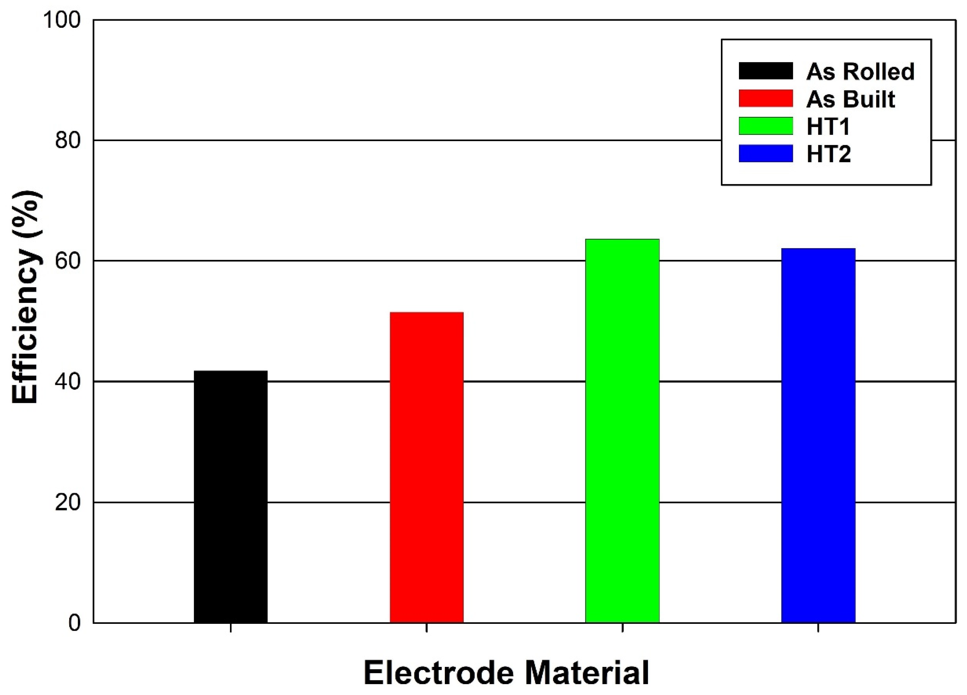
The gas production efficiency depends on the value of the passing current and the resultant gas flow rate. The bar graph in
Figure 8 illustrates the HHO gas production efficiency for the different electrode materials at a passing current of 8 amps. The as-rolled electrode exhibits the lowest efficiency at 41.81%, while the as-built electrode shows a moderate improvement, reaching approximately 51.52%.
Electrodes subjected to post-processing heat treatments (PPHTs) demonstrate significantly enhanced efficiencies. The HT1 electrode achieves an efficiency of 63.63%, whereas the HT2 electrode attains the highest efficiency at 62.11%. These results indicate that post-processing heat treatments play a crucial role in improving HHO gas production efficiency.
3.2. Hydrogen Embrittlement of 316L Stainless Steel Under Different Hydrogen Storage Conditions
The effect of hydrogen embrittlement (HE) on the mechanical properties and fracture morphology of additively manufactured (AM) 316L stainless steel was investigated under various simulated hydrogen storage conditions. Tensile and Charpy impact tests were conducted to evaluate the influence of hydrogen embrittlement on mechanical performance before and after electrochemical hydrogen charging.
Testing was performed at room temperature, simulating compressed hydrogen gas storage conditions, and in a liquid nitrogen environment, representing cryo-compressed and liquid hydrogen storage. The alloy exhibiting the highest resistance to hydrogen embrittlement in each condition was identified.
3.2.1. Tensile Properties Under Different Hydrogen Storage Conditions
Effect of Hydrogen Charging and Testing at Room Temperature
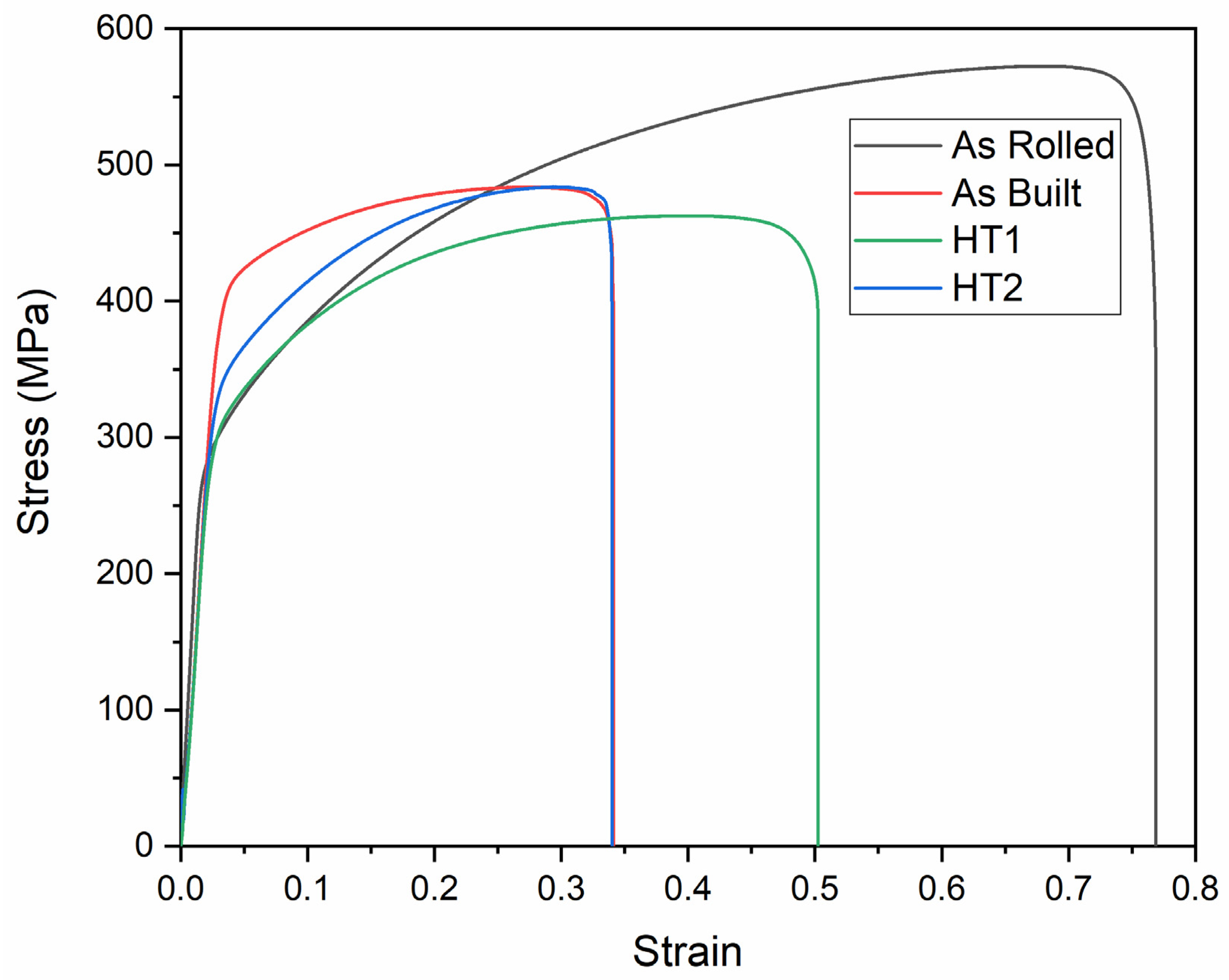
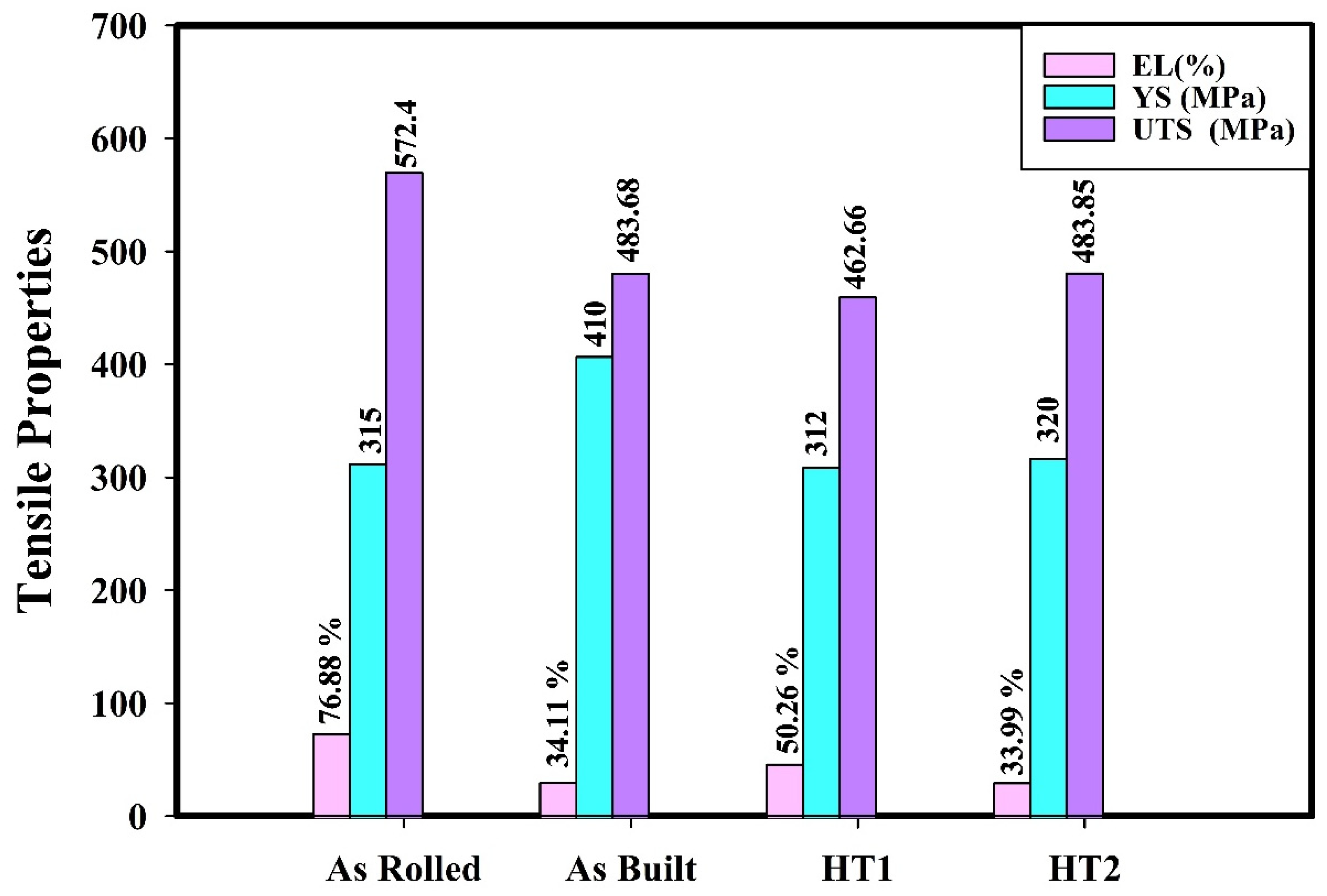
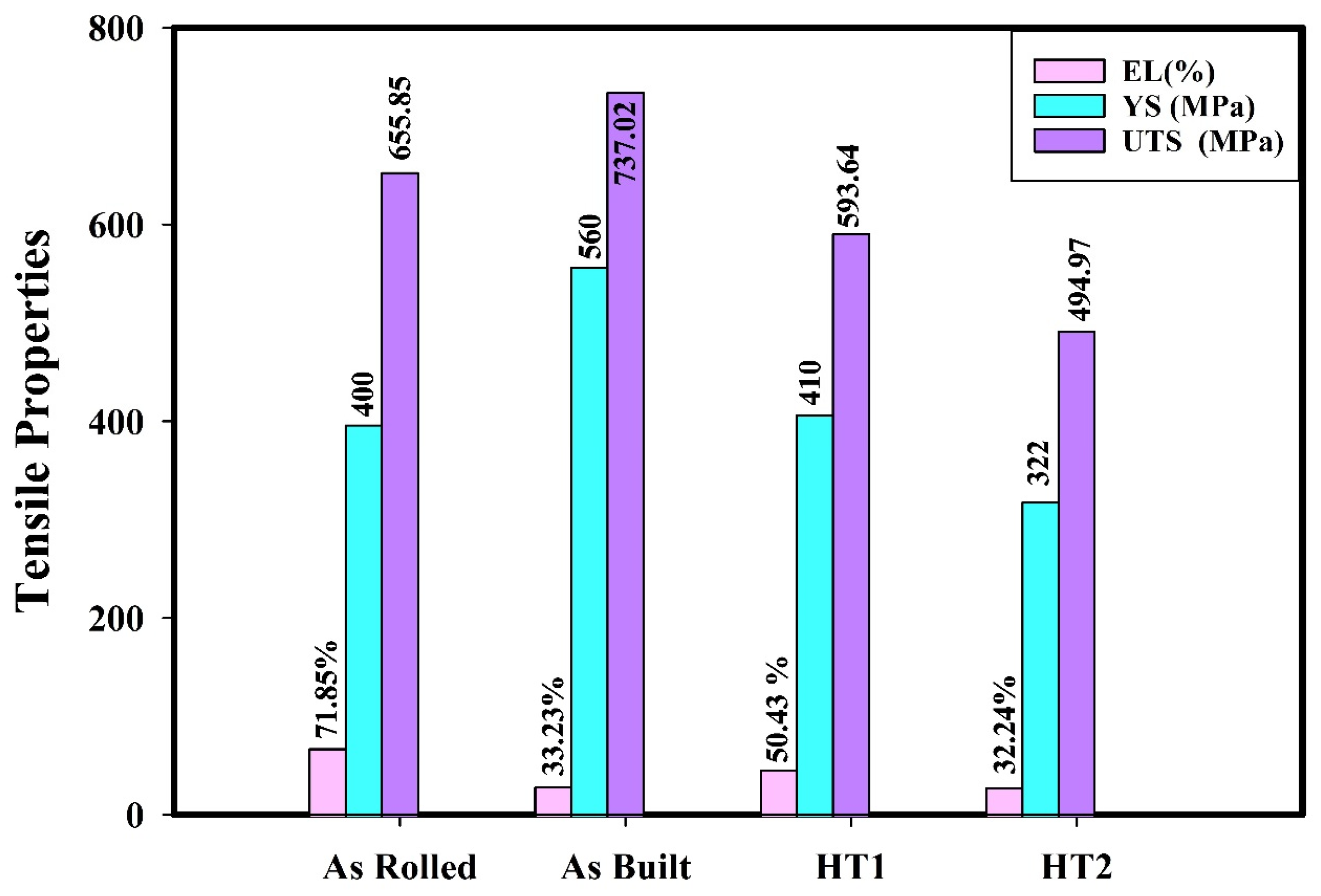
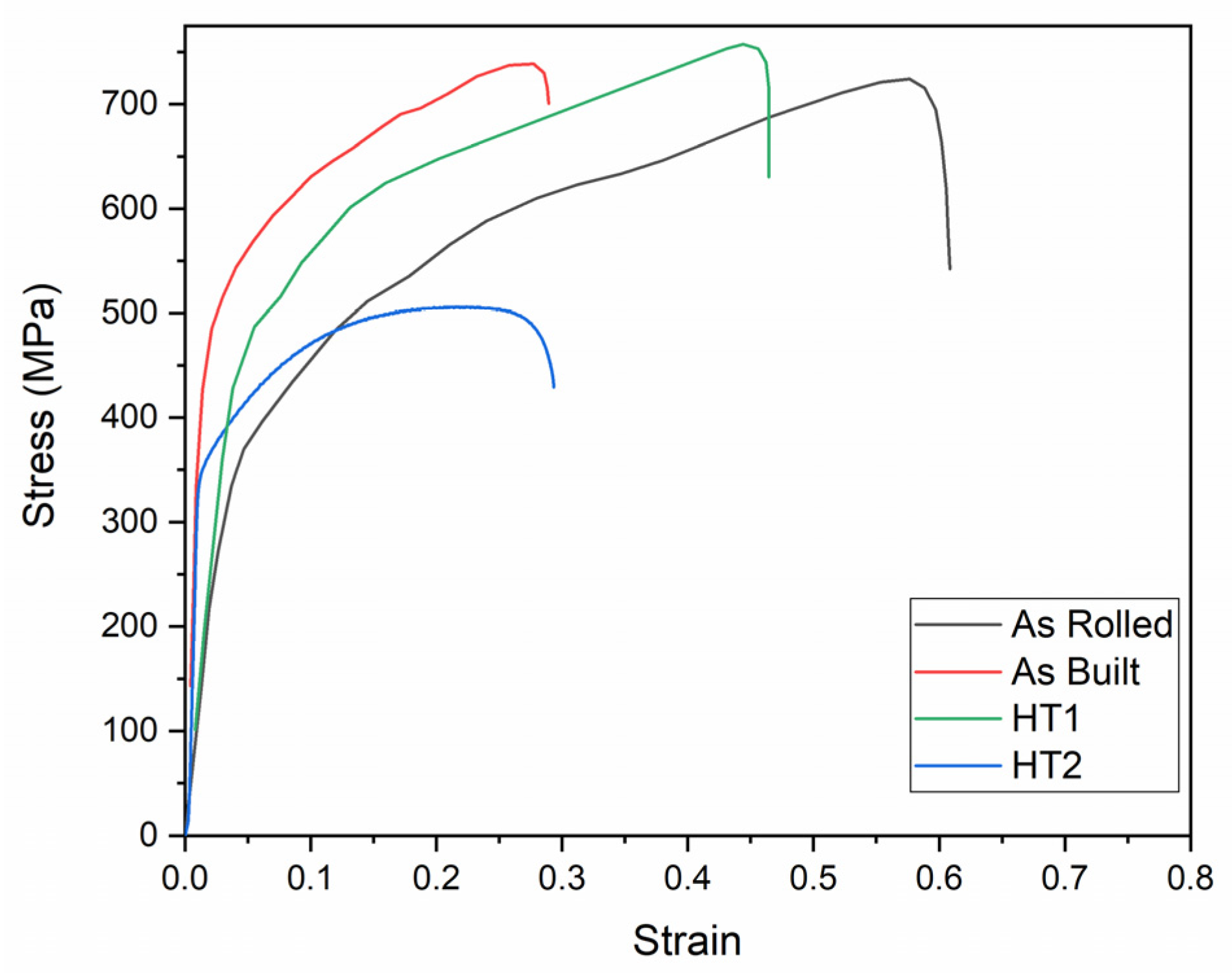
The tensile properties of 316L stainless steel in its as-rolled, as-built, HT1, and HT2 conditions were evaluated at room temperature (testing condition 1).
Figure 9 presents the engineering tensile stress–strain curves, while
Figure 10 summarizes the tensile property values for each processing condition at room temperature.
As observed from the results, the as-built specimen exhibits lower ultimate tensile strength (UTS) and elongation compared to the as-rolled specimen, but it demonstrates a 30.15% higher yield strength. This difference is primarily attributed to the higher strain hardening in as-rolled specimens due to stress-induced martensitic transformation, which occurs more significantly in wrought materials than in additively manufactured (AM) specimens [
9].
Claeys et al. [
9] reported that AM 316L stainless steel exhibits greater resistance to phase transformation than wrought 316L stainless steel due to its high dislocation density, which increases the stress required for martensite formation. The higher yield strength observed in AM materials is mainly due to their increased dislocation density and the formation of a dislocation substructure [
9,
21]. As a result, AM 316L stainless steel is well-suited for high-stress and high-pressure applications, as it can sustain higher loads without undergoing plastic deformation.
Post-processing heat treatment (PPHT) results in relatively higher work hardening during deformation compared to the as-built material [
9]. The HT1 treatment positively impacts elongation, as annealing reduces residual stresses in the as-built condition while also lowering strength due to a decrease in dislocation density. The reduction in dislocation density allows dislocations to nucleate and migrate more freely during deformation, improving ductility [
9,
21].
Conversely, the HT2 treatment has a minimal effect on the mechanical properties of the as-built material. This limited impact may be attributed to partial recrystallization and associated grain refinement during the short holding time at 1050 °C; moreover, the quenching effect may counterbalance the high cooling rates experienced during the additive manufacturing process, which contributes to a high dislocation density.
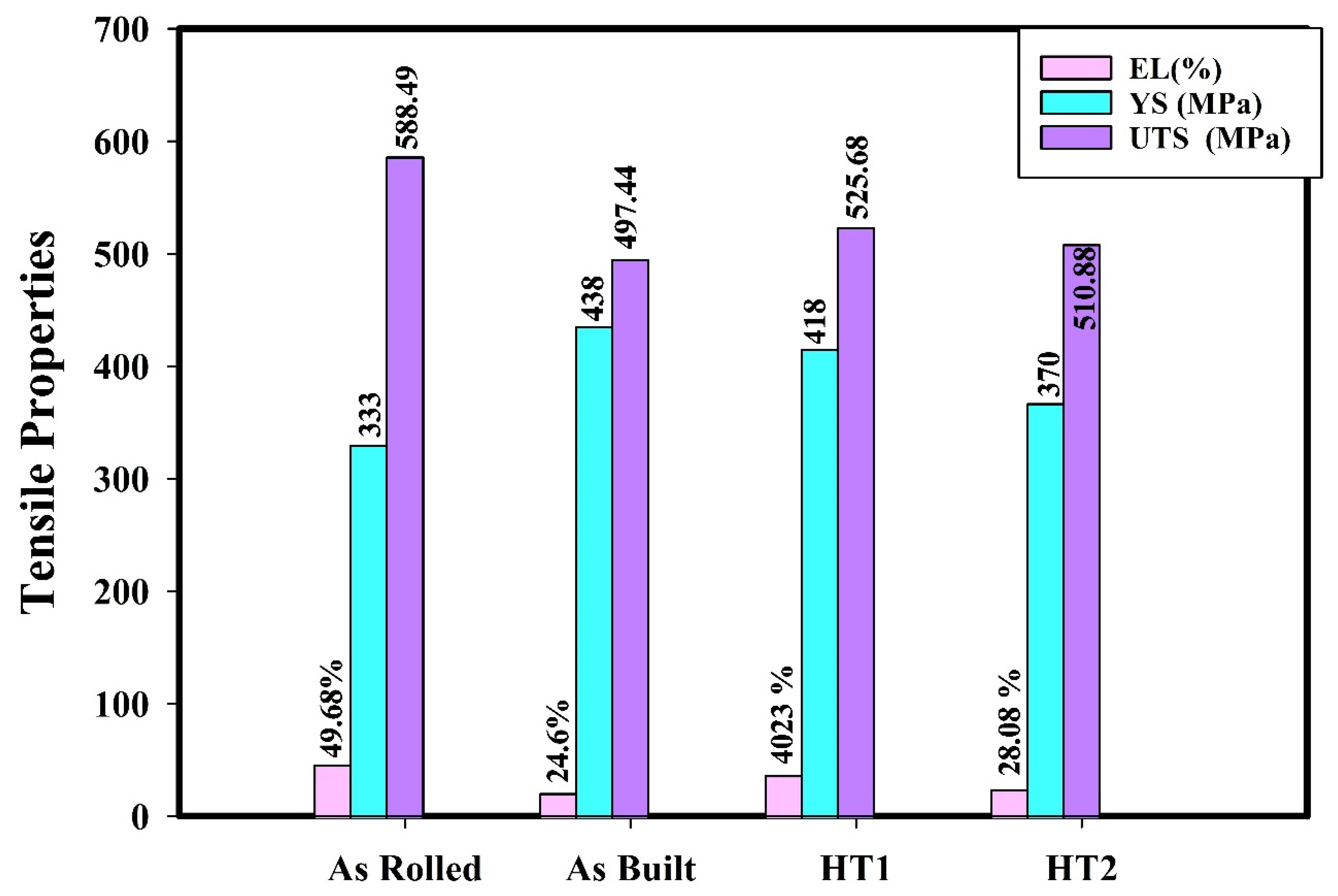
The engineering tensile stress–strain curves and tensile properties of the hydrogen-charged specimens tested at room temperature (testing condition 2) are presented in
Figure 11 and
Figure 12, respectively. As observed, hydrogen charging has a consistent and significant effect on the tensile properties of 316L stainless steel across all material conditions.
In all cases, hydrogen-charged specimens exhibit higher strength and lower elongation compared to those tested under Condition 1 (without hydrogen charging). This behavior occurs because hydrogen reduces plastic deformation, thereby inhibiting strain-induced martensite transformation. Furthermore, post-processing heat treatments mitigate the impact of hydrogen on tensile properties compared to the as-built material. These findings align with previous studies [
7,
9,
23].
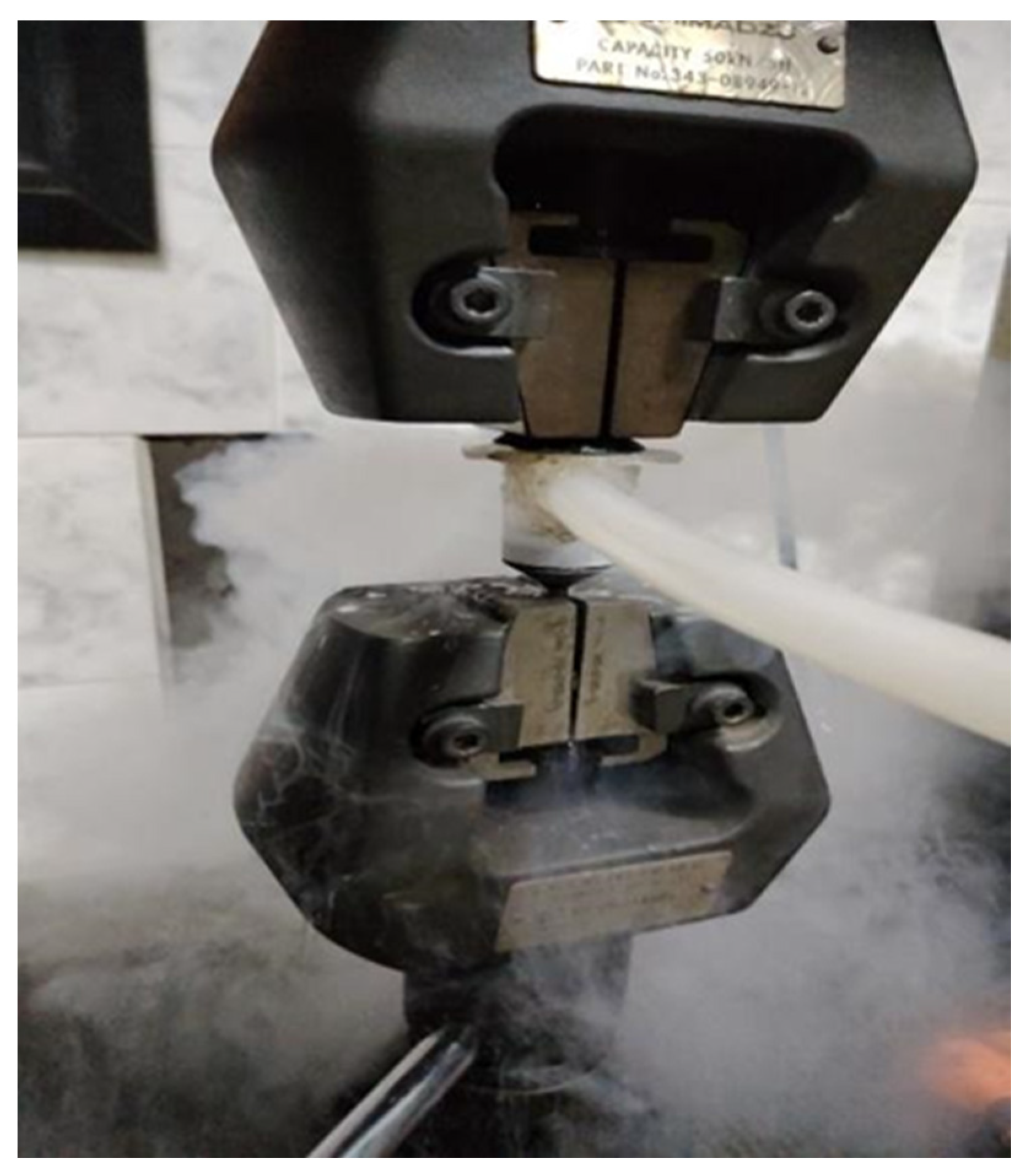
Influence of Hydrogen Charging and Testing at Cryogenic Temperature
To assess the effect of cryogenic temperature (−196 °C) on the tensile properties of 316L stainless steel, specimens were tested in a liquid nitrogen environment (testing condition 3). The engineering tensile stress–strain curves for Condition 3 are shown in
Figure 13, while the corresponding tensile property values are presented in
Figure 14.
Compared to Condition 1 (room temperature testing), cryogenic testing significantly increases the strength of all specimens. This enhancement is primarily attributed to martensitic transformation occurring during deformation at cryogenic temperatures due to the material’s low stacking fault energy at low temperatures, as previously reported by Wang et al. [
21].
The elongation of the as-rolled specimen decreases by 6.5% compared to its performance at room temperature (testing condition 1). However, the effect of cryogenic testing on elongation is less pronounced in additively manufactured specimens than in the as-rolled specimen. This difference is attributed to the non-linear hardening behavior induced by the transformation-induced plasticity (TRIP) phenomenon, as previously reported by Wang et al. [
21].
The engineering tensile stress–strain curves and tensile properties of hydrogen-charged specimens tested at cryogenic temperature (testing condition 4) are presented in
Figure 15 and
Figure 16, respectively.
As observed, hydrogen charging exhibits a consistent effect on the tensile properties of 316L stainless steel across all material conditions at cryogenic temperature. In all cases, hydrogen-charged specimens demonstrate higher strength and lower elongation compared to specimens tested at cryogenic temperature without hydrogen charging (testing condition 3). These findings align with previously published results [
20,
21,
30].
Hydrogen Embrittlement Evaluation Using Tensile Properties
Hydrogen embrittlement refers to the detrimental effect of hydrogen on mechanical properties. The behavior of hydrogen embrittlement in 316L stainless steel is significantly influenced by the manufacturing conditions and the resulting microstructure. As previously mentioned [
9,
23,
27], the as-built structure’s high dislocation density and cell boundary serve as hydrogen traps, lowering hydrogen diffusivity and postponing the spread of cracks. If properly dispersed, these traps can reduce hydrogen embrittlement, although large stress concentrations can also serve as fracture nucleation sites. High grain boundary areas in the fine microstructure of additively created 316L stainless steel serve as hydrogen traps, particularly at high angles, and carbide precipitation at grain boundaries raises the danger of hydrogen embrittlement.
To assess hydrogen embrittlement susceptibility at room temperature, the total elongation at failure of specimens tested in normal air (testing condition 1) was compared with that of hydrogen-charged specimens tested at room temperature (testing condition 2). This comparison quantifies the changes in mechanical properties and evaluates the influence of hydrogen on 316L stainless steel under conditions simulating compressed hydrogen gas storage.
To evaluate the hydrogen embrittlement susceptibility of 316L stainless steel under cryogenic conditions, the total elongation at failure of specimens tested at cryogenic temperature (testing condition 3) was compared with that of hydrogen-charged specimens tested at cryogenic temperature (testing condition 4). This comparison simulates the storage conditions of liquid and cryo-compressed hydrogen.
The hydrogen embrittlement index (HEI) was calculated at both room temperature and cryogenic temperature based on the total elongation at fracture, using the following equation [
7,
9]:
where El
un represents the elongation at fracture of the uncharged specimens, and El
H denotes the elongation at fracture of the hydrogen-charged specimens.
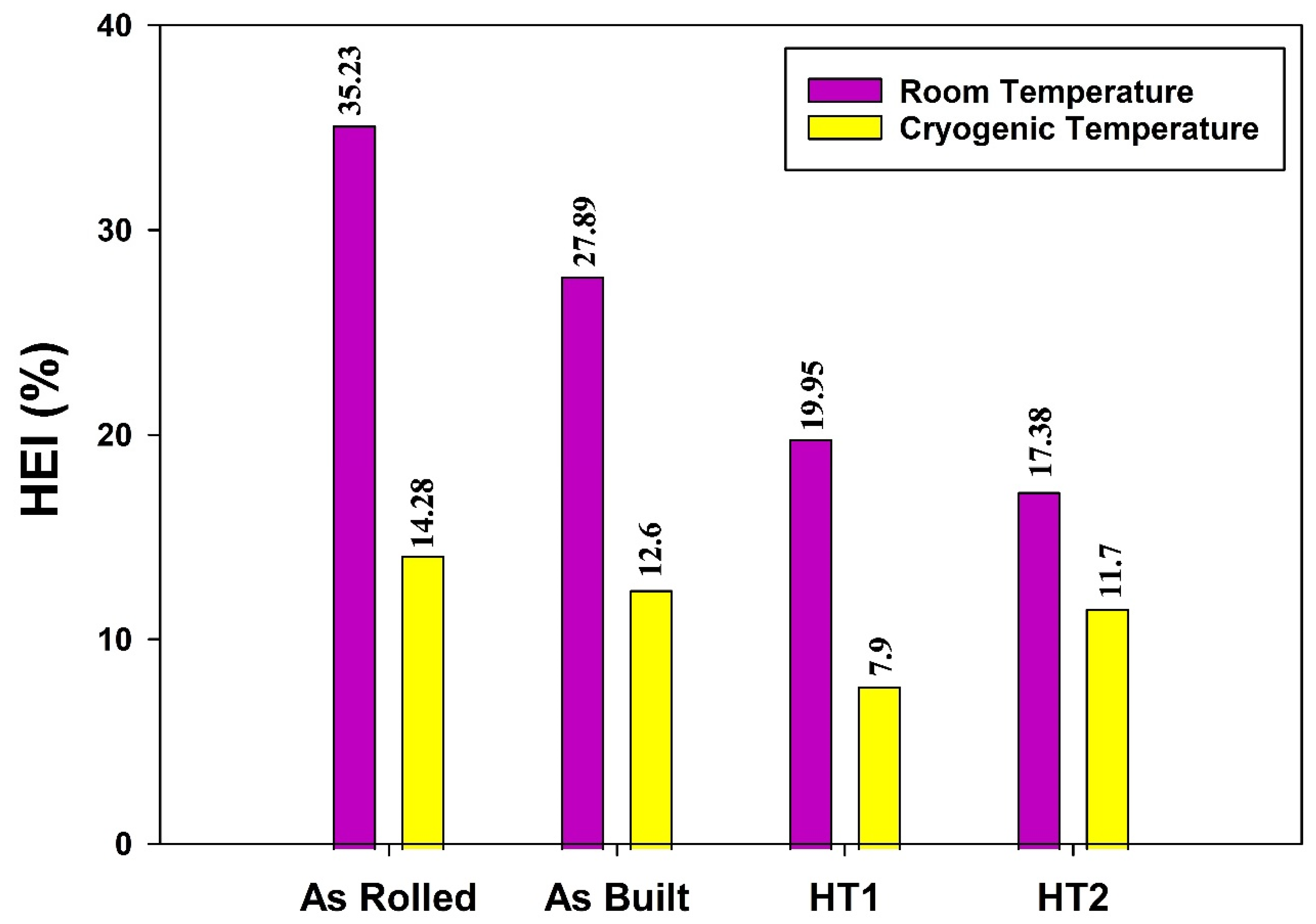
Figure 17 presents the calculated HEI values, determined using Equation (4), for the as-rolled, as-built, HT1, and HT2 specimens at both room temperature and cryogenic temperature. The HEI quantifies the loss of ductility caused by the introduction of hydrogen atoms into the microstructure during electrochemical charging. Lower HEI values indicate higher resistance to hydrogen embrittlement, demonstrating that hydrogen has a minimal impact on the mechanical behavior of 316L stainless steel.
It can be observed that hydrogen embrittlement resistance improves at cryogenic temperature (testing condition 4) across all material conditions compared to room temperature (testing condition 2). Although cryogenic temperatures enhance the propensity for strain-induced martensite formation and deformation twinning, as described by Alvarez et al. [
20], the dominant effect at low temperatures is the reduction in hydrogen diffusion, which mitigates embrittlement.
It is evident that hydrogen had minimal impact on post-processed heat-treated (PPHT) specimens. The PPHT process effectively eliminated hydrogen sensitivity and mitigated hydrogen embrittlement (HE) susceptibility by stabilizing the dislocation morphology and enhancing resistance to martensite transformation. This highlights the high efficiency of additively manufactured (AM) 316L stainless steel in resisting hydrogen embrittlement, aligning with the findings of Bertsch et al. [
23].
The results reveal that additively manufactured (AM) specimens exhibit higher hydrogen embrittlement resistance compared to as-rolled specimens. Moreover, the post-processing heat treatments (PPHTs) further enhance the hydrogen embrittlement resistance of AM materials at both room and cryogenic temperatures. This improvement is attributed to the reduced propensity for strain-induced martensite formation in AM 316L stainless steel, which decreases hydrogen embrittlement susceptibility, as reported by Alvarez et al. [
20].
It is observed that the HT2 condition is the most suitable material condition for compressed hydrogen gas storage, as it exhibits the lowest HEI at room temperature. Conversely, the HT1 condition is the most favorable for liquid and cryo-compressed hydrogen storage, demonstrating the lowest HEI at cryogenic temperature.
This behavior can be linked to the microstructural characteristics of each condition. In HT2, the quenched microstructure typically contains martensite, high residual stress, and structural defects resulting from water quenching. These features contribute to superior hydrogen embrittlement resistance at room temperature, as they hinder hydrogen diffusion more effectively compared to the as-built and HT1 conditions.
On the other hand, the annealed structure of HT1, which has fewer residual stresses, exhibits the best hydrogen embrittlement resistance at cryogenic temperatures. This is because the high residual stress present in the as-built and HT2 specimens tends to increase further at cryogenic temperatures, thereby heightening hydrogen embrittlement susceptibility.
This observation highlights the ability of AM 316L stainless steel to maintain its mechanical integrity and surface properties in hydrogen environments at both room and cryogenic temperatures, demonstrating its suitability for hydrogen storage and related applications.
3.2.2. Impact Toughness and Fractography at Different Hydrogen Storage Conditions
Hydrogen Embrittlement Evaluation Using Impact Toughness
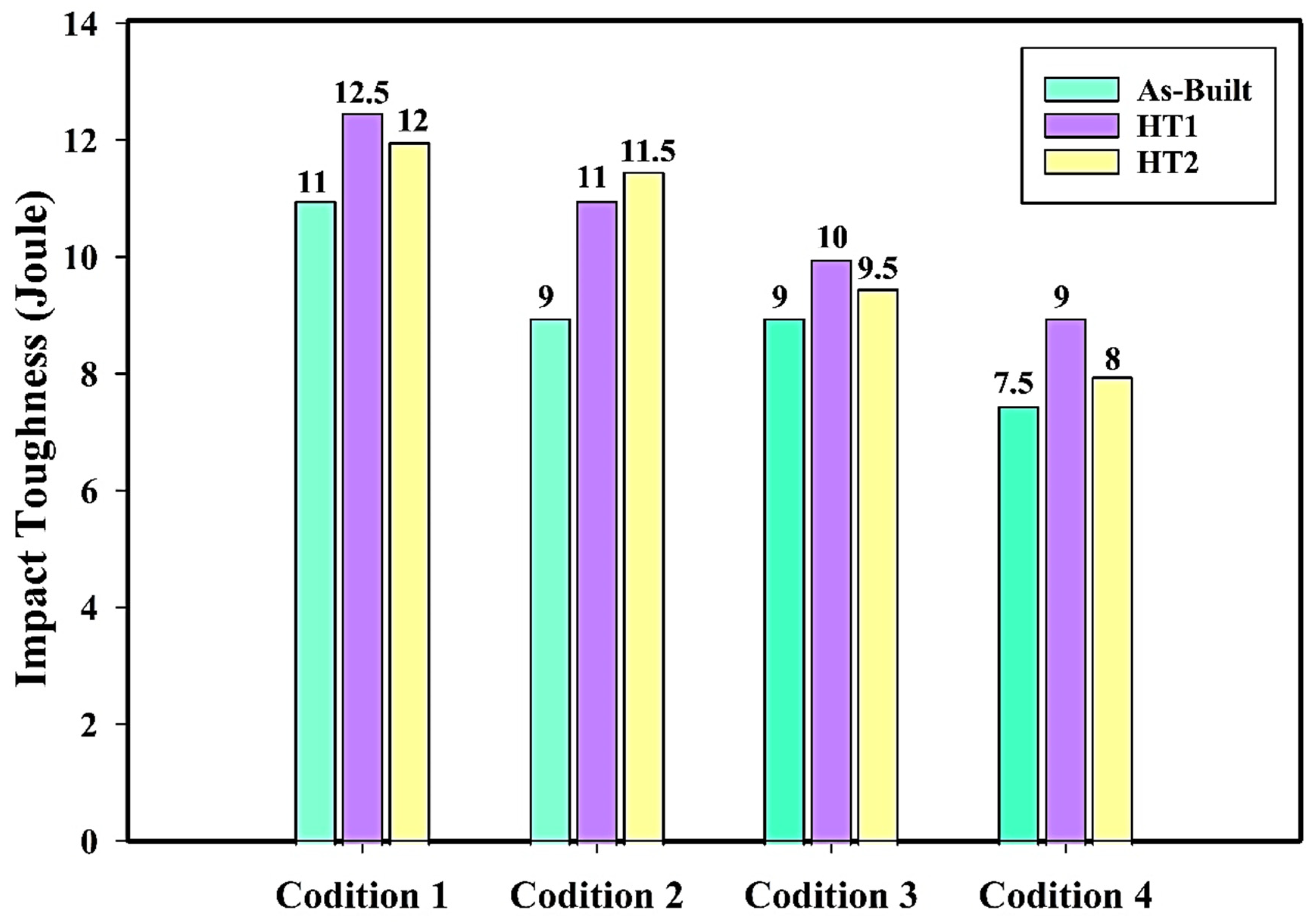
Charpy impact toughness was measured for additively manufactured and post-processed 316L stainless steel specimens, as shown in
Figure 18. Impact testing at room temperature (testing condition 1) revealed no significant differences in impact toughness, with a slight improvement observed in post-processed conditions.
In testing condition 2, where specimens were hydrogen-charged prior to impact testing, a reduction in impact toughness was observed across all material processing conditions. A similar trend was noted in Testing Condition 4 compared to Testing Condition 3, where specimens tested at cryogenic temperature exhibited lower impact values after hydrogen charging.
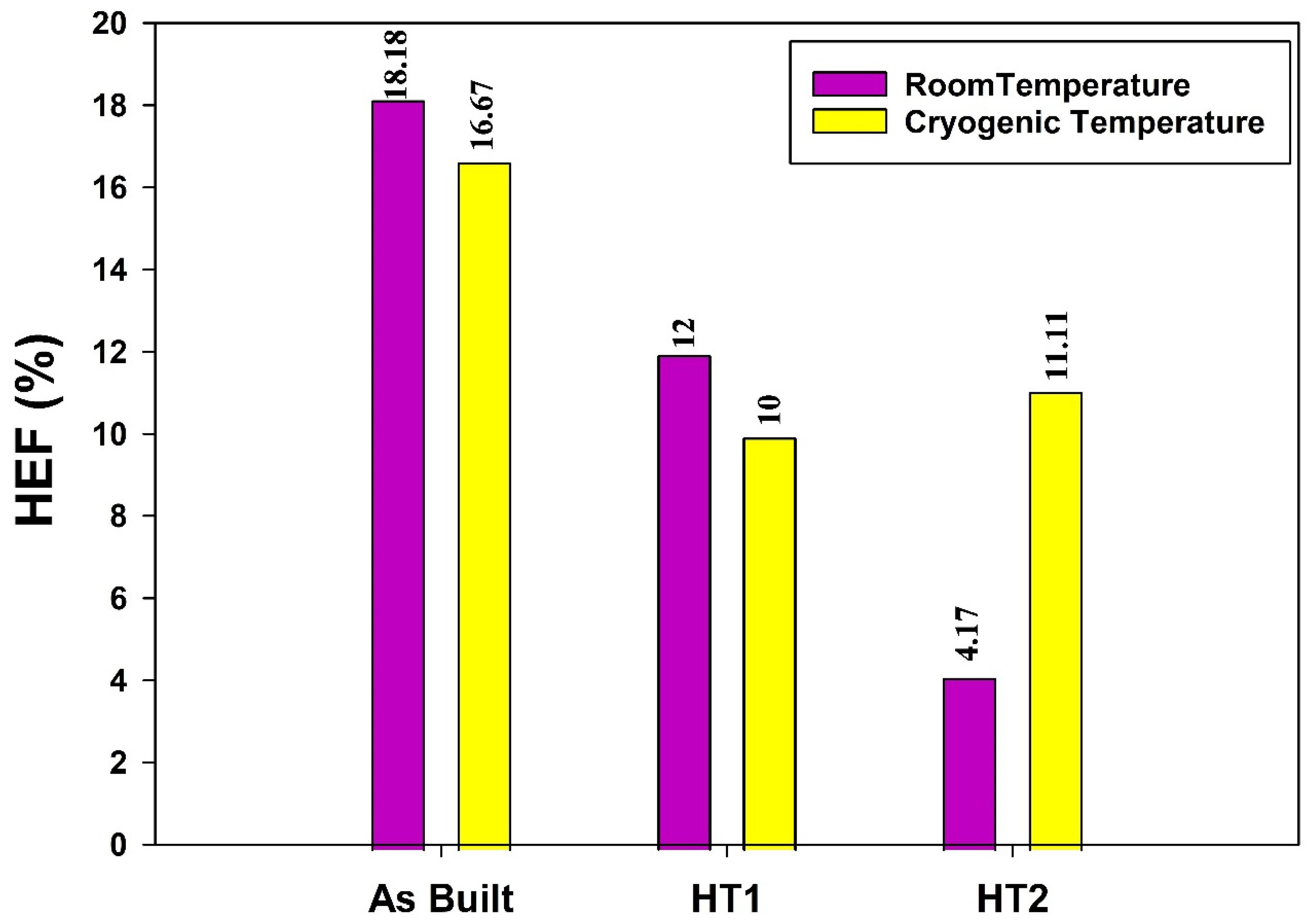
The hydrogen embrittlement factor (HEF) was calculated at both room and cryogenic temperatures to quantify the reduction in Charpy impact toughness after electrochemical hydrogen charging, using the following equation [
13]:
where U
un represents the Charpy impact toughness of the uncharged specimens (in Joules), and U
H denotes the Charpy impact toughness of the hydrogen-charged specimens (in Joules).
The hydrogen embrittlement factors, based on the reduction in impact toughness after hydrogen charging at both room and cryogenic temperatures, are presented in
Figure 19. The results indicate that post-processing heat treatments positively influence hydrogen embrittlement resistance across both temperature conditions. Notably, the HT2 condition exhibits the highest resistance to hydrogen embrittlement at room temperature, making it the most suitable choice for processing AM 316L stainless steel tanks intended for compressed hydrogen gas storage at ambient conditions. Conversely, the HT1 condition demonstrates superior resistance to hydrogen embrittlement at cryogenic temperatures, making it the optimal material for AM 316L stainless steel tanks used in liquid and cryo-compressed hydrogen storage applications.
The hydrogen embrittlement behavior of different AM 316L stainless steel alloys can be attributed to the influence of the additive manufacturing process on the hydrogen solubility and diffusivity. As reported by Claeys et al. [
9], AM increases hydrogen solubility while reducing its diffusivity due to a higher number of trapping sites. This structural characteristic allows the AM material to dissolve introduced hydrogen atoms more effectively, preventing their segregation and thereby mitigating their detrimental effects. The HEF results further validate the trends observed in the HEI measurements.
Fractography at Different Hydrogen Storage Conditions
The environmental embrittlement occurs due to the adsorption of hydrogen molecules on the surface, which subsequently dissociate into atomic hydrogen. This atomic hydrogen can migrate across the surface and diffuse into the material during mechanical deformation. The failure of the metal is influenced by the transport and accumulation of hydrogen within the triaxial tensile stress field ahead of a crack tip. Hydrogen embrittlement (HE) increases the likelihood of sudden brittle failure, compromising the material’s mechanical integrity.
This section describes the fractography analysis of as-built and HT2 specimens under different testing conditions to provide insights into the fracture mechanisms at various hydrogen storage conditions.
Figure 20,
Figure 21,
Figure 22,
Figure 23,
Figure 24 and
Figure 25 present low- and high-magnification SEM micrographs of the fracture surfaces of as-built and HT2 specimens tested under different conditions: uncharged at room temperature (Testing Condition 1), hydrogen-charged and tested at room temperature (Testing Condition 2), simulating hydrogen gas storage, and hydrogen-charged and tested at cryogenic temperature (Testing Condition 4), simulating the storage conditions of liquid and cryo-compressed hydrogen.
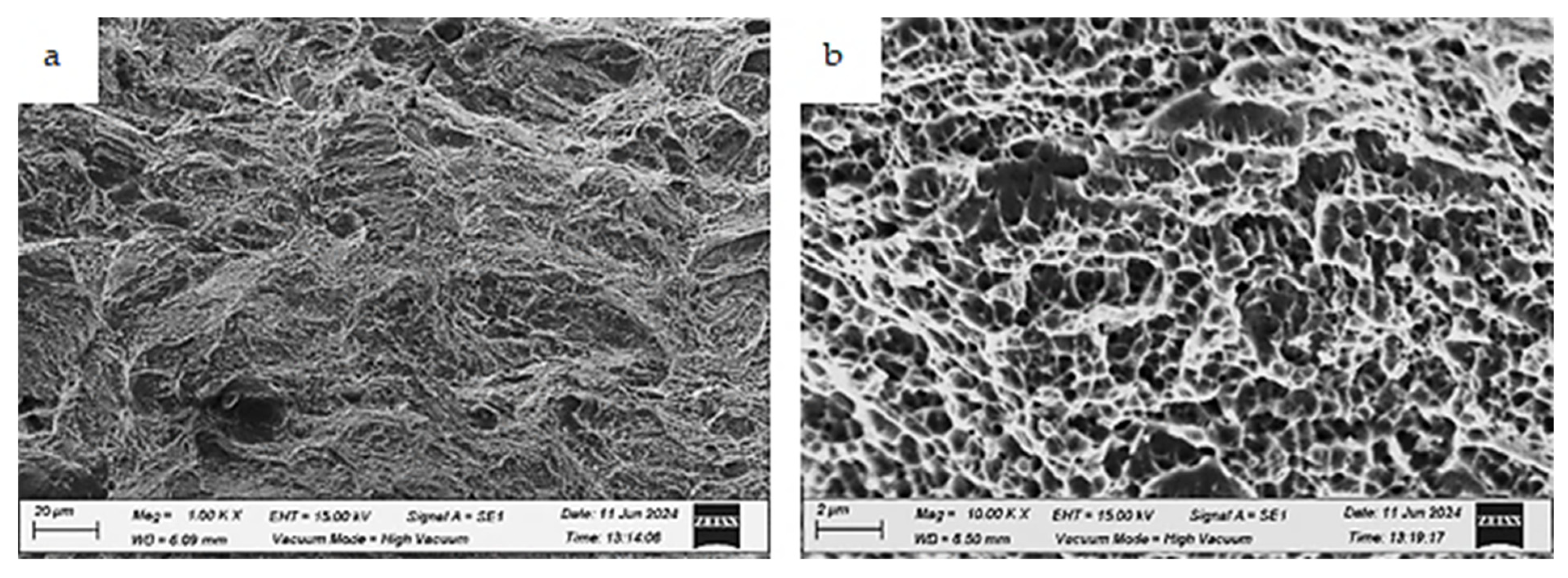
The fracture morphologies of the as-built, uncharged specimen (testing condition 1) are shown in
Figure 20. At low magnification, a few isolated cleavage facets are apparent (
Figure 20a). The fracture surface exhibits a ductile fracture with homogeneously distributed fine dimples (
Figure 20b).
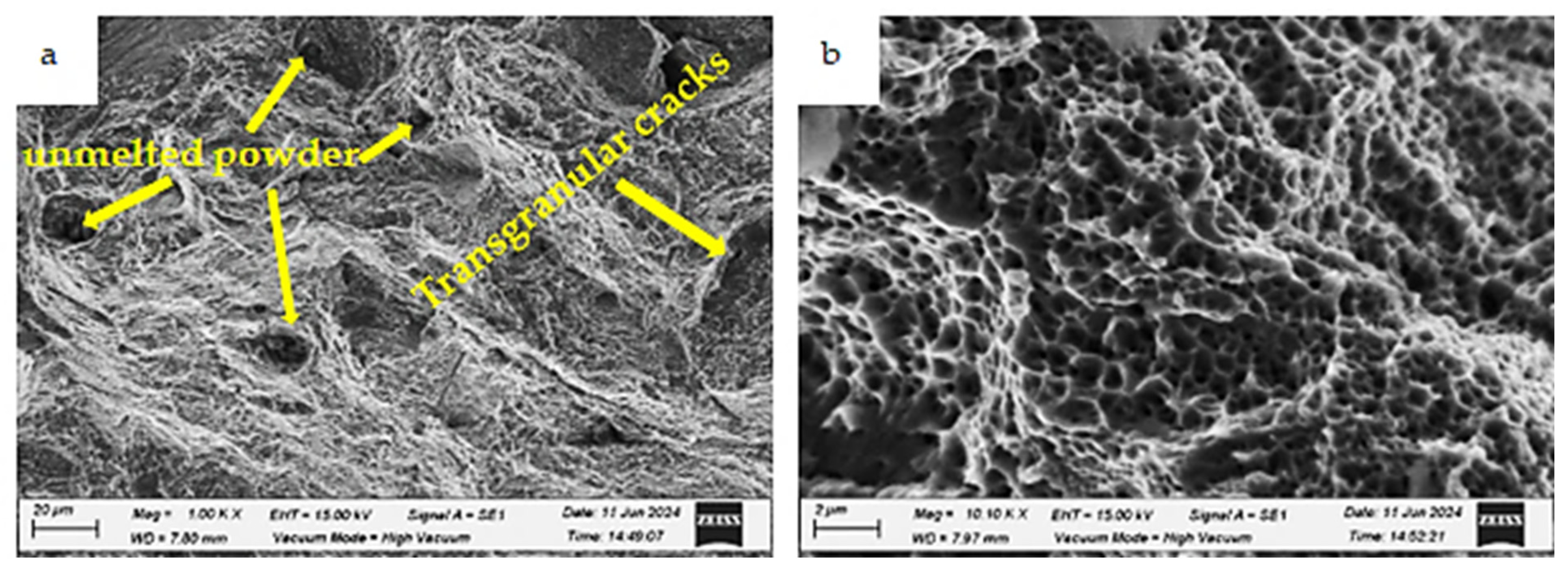
The fracture surface of the as-built specimen charged with hydrogen (testing condition 2) also exhibits a ductile fracture but with a lower fraction of dimples and some isolated cleavage facets, as shown in
Figure 21b. At low magnification, transgranular cracks are evident and marked by white arrows (
Figure 21a). Similar results have been reported in a previous study [
30].
Figure 22 presents the fracture surface of the as-built specimen charged with hydrogen and tested in a liquid nitrogen environment (testing condition 4). Despite a loss of ductility, most of the observed area retains a ductile nature, though it exhibits the lowest fraction of fine dimples compared to Conditions 1 and 2. Additionally, some transgranular cracks and unmelted powder are observed, as indicated by white arrows (
Figure 22a). This explains the reduction in impact toughness at this condition to 7.5 J.
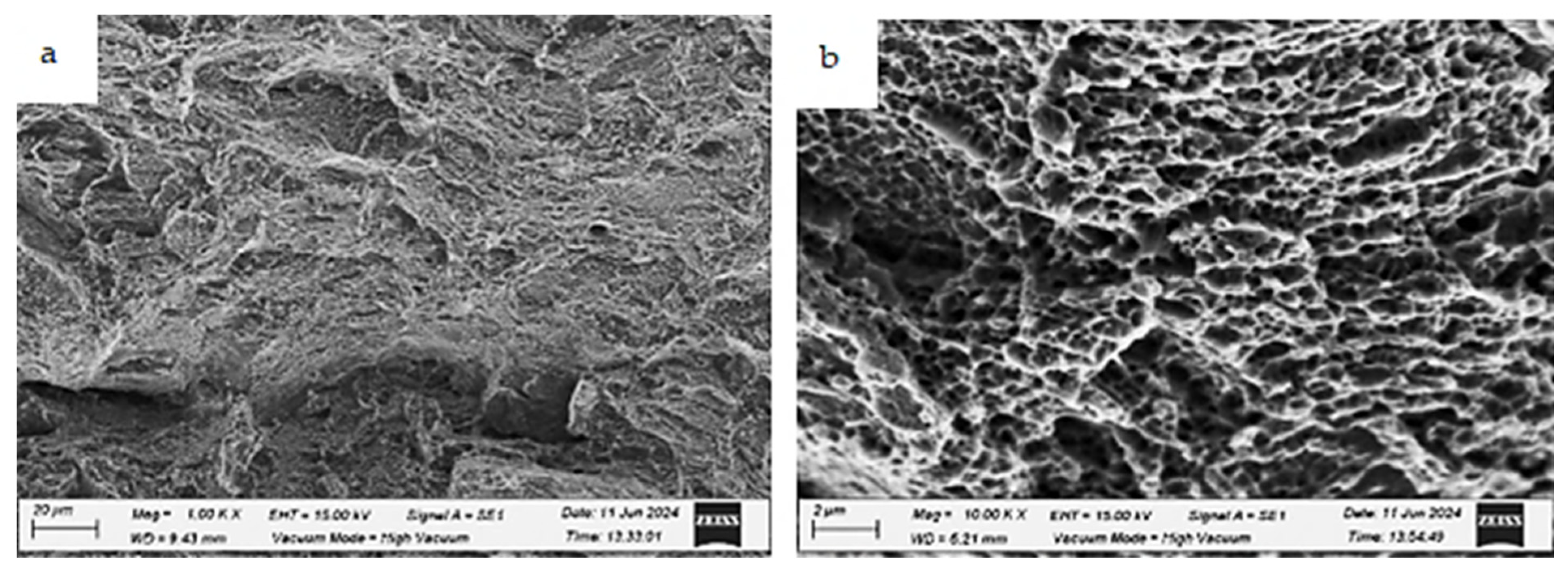
The fracture morphology of the uncharged HT2 specimen (testing condition 1) is shown in
Figure 23. Evidence of ductile fracture is observed, characterized by fine dimples and some isolated cleavage facets. Additionally, ductile microvoid formation is present.
In testing condition 2, where the HT2 specimen was hydrogen-charged and tested at room temperature, transgranular cracks and ductile microvoid formation are observed, as shown in
Figure 24. Despite the presence of hydrogen, the fracture surface largely retains its ductile nature. While hydrogen exposure generally reduces ductility and increases HE susceptibility to fracture, the applied heat treatment mitigates the effects of hydrogen embrittlement.
Subjecting AM 316L stainless steel to a holding temperature of 1050 °C followed by quenching enhances its resistance to hydrogen embrittlement. This improvement can be attributed to the increased atomic density and reduced microstructural gaps, which hinder hydrogen penetration and lower its diffusion coefficient.
Figure 25 shows the fracture surface of the HT2 specimen after hydrogen charging and testing in a liquid nitrogen environment. The fracture surface predominantly retains its ductile nature; however, some unmelted particles and microvoids are visible. The analysis of the fracture surfaces supports the current findings, aligning with results reported in previous studies [
20,
30].
3.3. Burst Pressure Estimation Using Static and Explicit Dynamics Analyses
The burst pressure of additively manufactured (AM) 316L stainless steel in the as-built condition was estimated using static structural and explicit dynamic analyses based on the equivalent von Mises stress theory.
Figure 26 presents the equivalent von Mises stress distribution at an operating pressure of 25 MPa, obtained using the static structural analysis. The relationship between the equivalent von Mises stress and the corresponding pressure was derived from the static structural analysis and is shown in
Figure 27. The burst pressure was determined as the pressure at which the equivalent von Mises stress reaches the ultimate tensile strength of the as-built 316L stainless steel. The results indicate that the estimated burst pressure is approximately 70 MPa.
Using the explicit dynamic analysis, a realistic simulation of the burst test was conducted. The stress value just before the explosion was observed, and the corresponding pressure was recorded as the burst pressure. The equivalent von Mises stress distributions just before and just after the explosion are illustrated in
Figure 28. The explicit dynamic analysis results indicate a burst pressure of 81 MPa, as shown in
Figure 29. Additionally, it can be observed that the burst pressure corresponding to the ultimate tensile strength (UTS) of the material is approximately 76 MPa based on the explicit dynamics results. This value represents the onset of material failure as it reaches its UTS. Therefore, the results obtained from both the static structural and explicit dynamic modules are in good agreement.
Ringel et al. [
17] experimentally determined the burst pressure of AM 316L stainless steel to be 70 MPa, which aligns with the present findings, thereby confirming the validity of both the current results and the employed analysis modules.
The burst testing results further demonstrate that the additive manufacturing process significantly enhances the burst pressure of Type 1 pressure vessels compared to conventionally manufactured counterparts. This indicates that additive manufacturing can be effectively utilized to produce high-safety and durable pressure vessels.


 ,
, 


