

Design and Validation of a SiC-Based Single-to-Three-Phase Converter for Low-Voltage Distribution Systems

Abstract
1. Introduction
1.1. Background
- Design a compact and modular STPC topology capable of generating a stable three-phase voltage from a single-phase input.
- Evaluate the performance of the STPC under various load conditions (nonlinear, unbalanced, and motor loads) through both simulation and field testing.
- Assess the applicability of the STPC in real PDS, especially in rural areas where a conventional three-phase supply is economically constrained.
1.2. Literature Review
2. Research Questions and Hypothesis
2.1. Research Questions
2.2. Hypothesis
3. Methodology
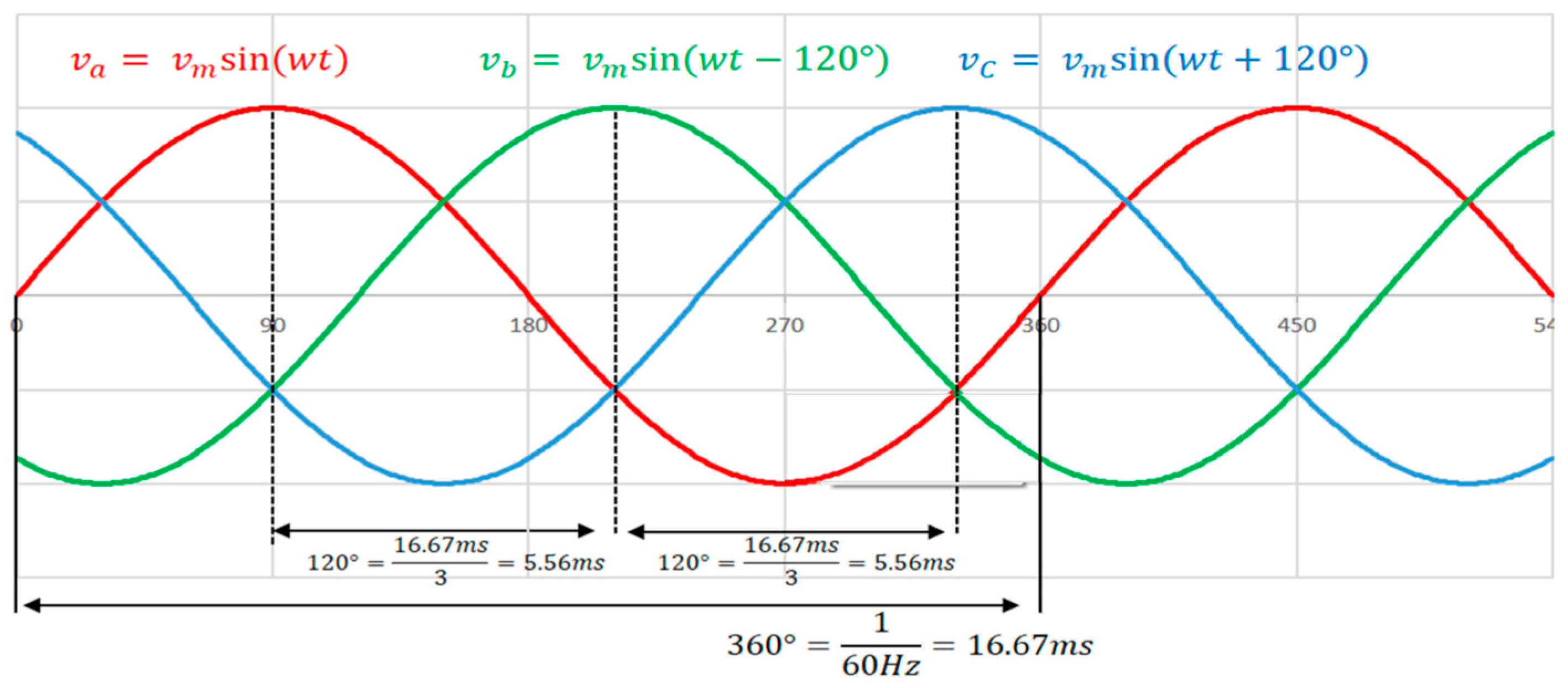
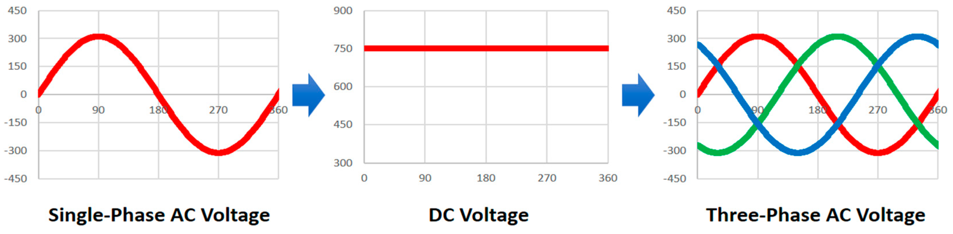
3.1. Three-Phase Voltage Conversion Method Using Power Semiconductors
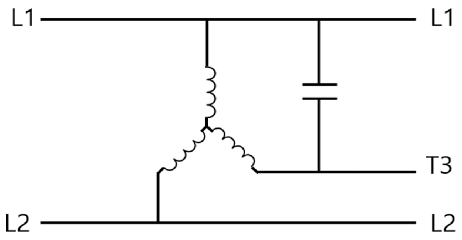
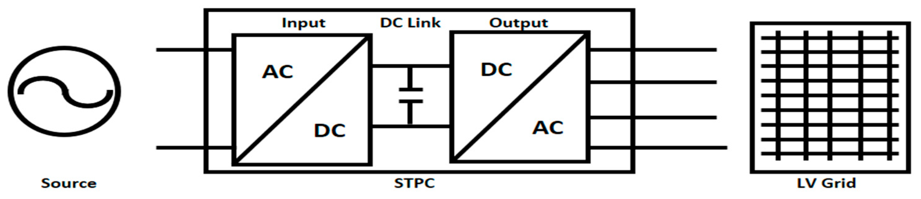
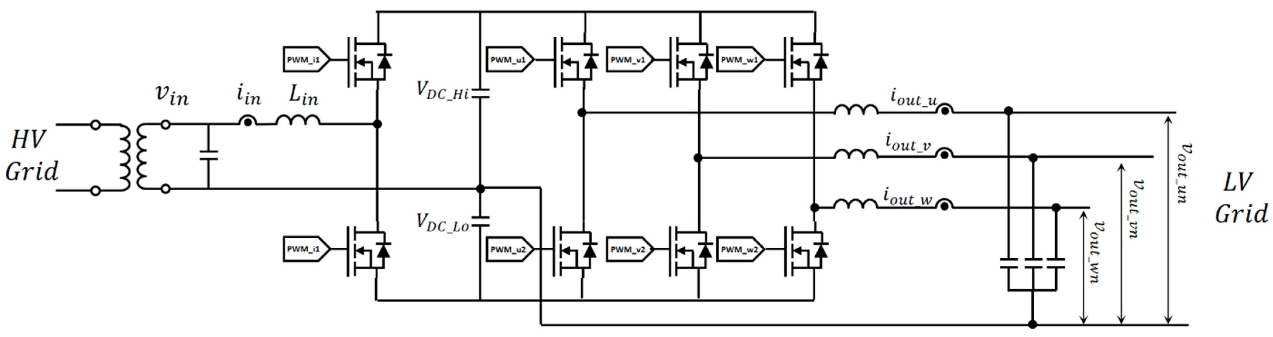
3.2. Topology
3.3. Control
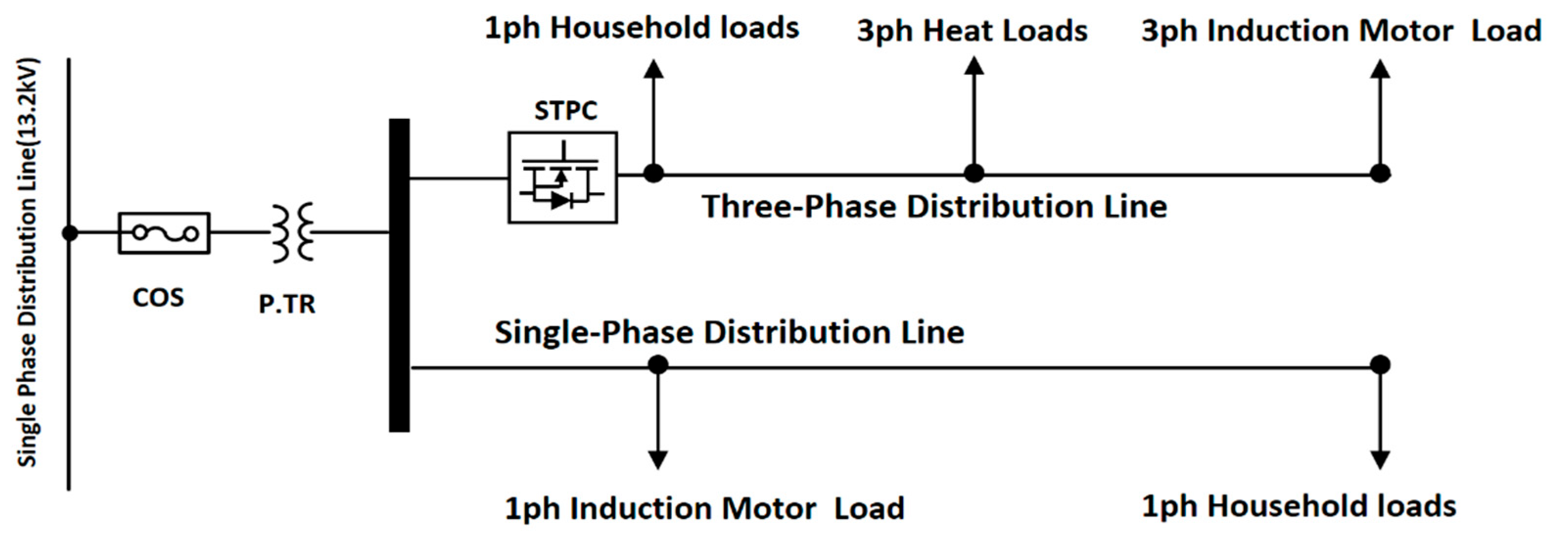
3.4. Connection to PDS
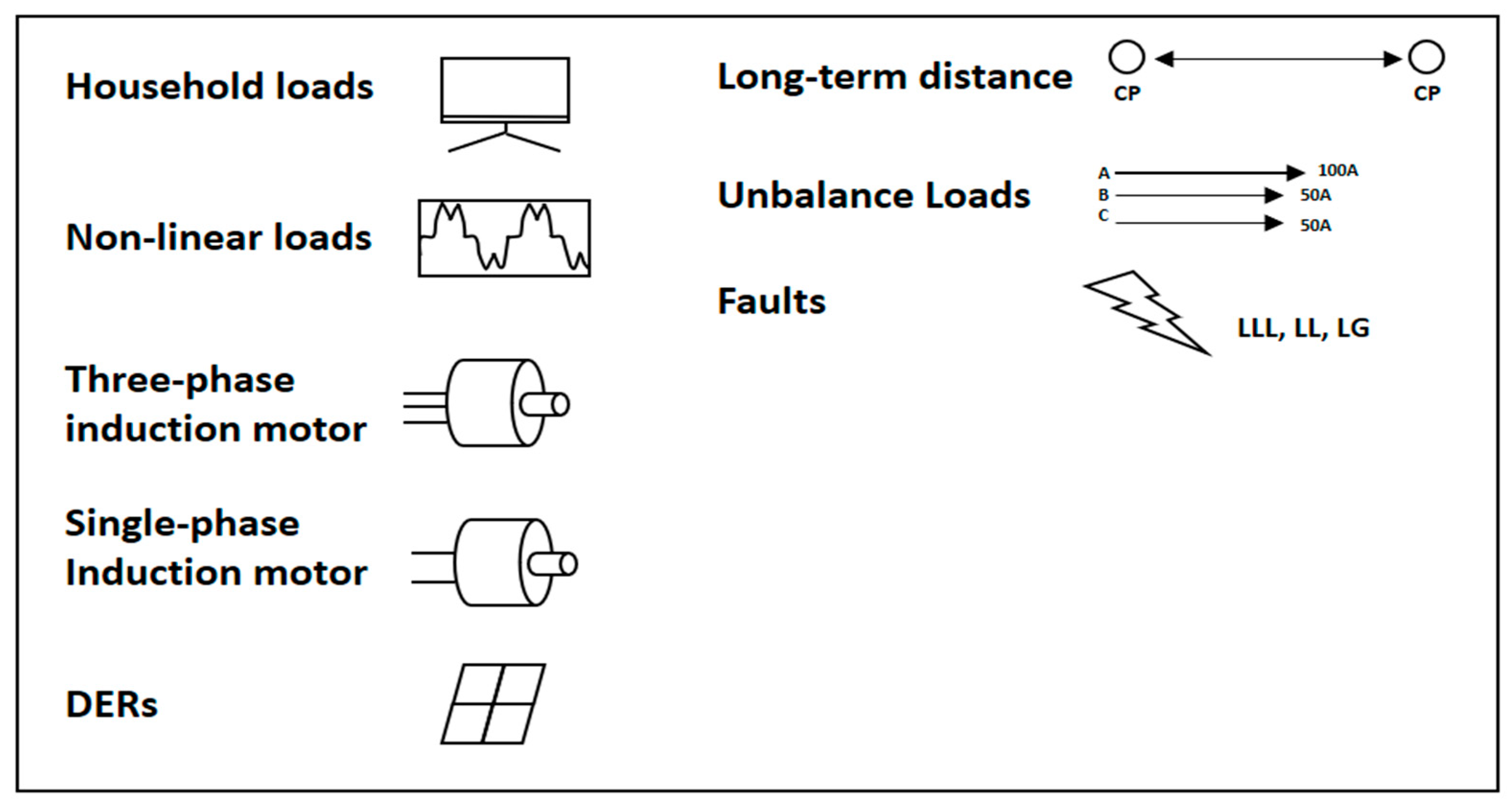
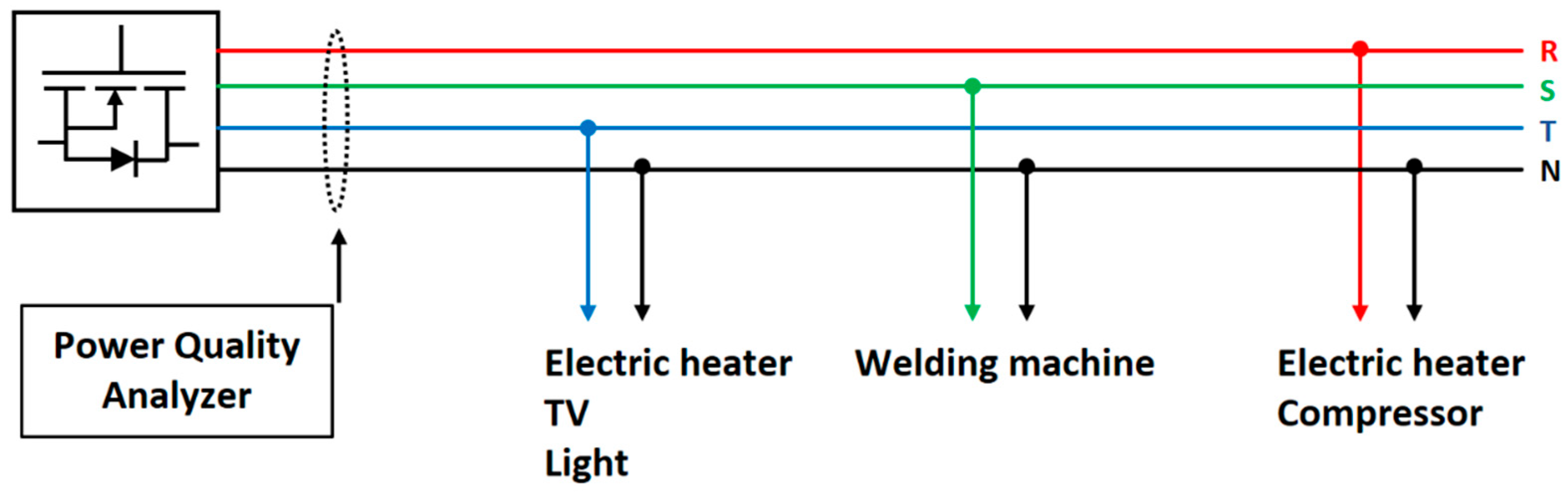
3.5. LV Loads on Distribution Lines
3.6. Test of LV Distribution Line
4. Result
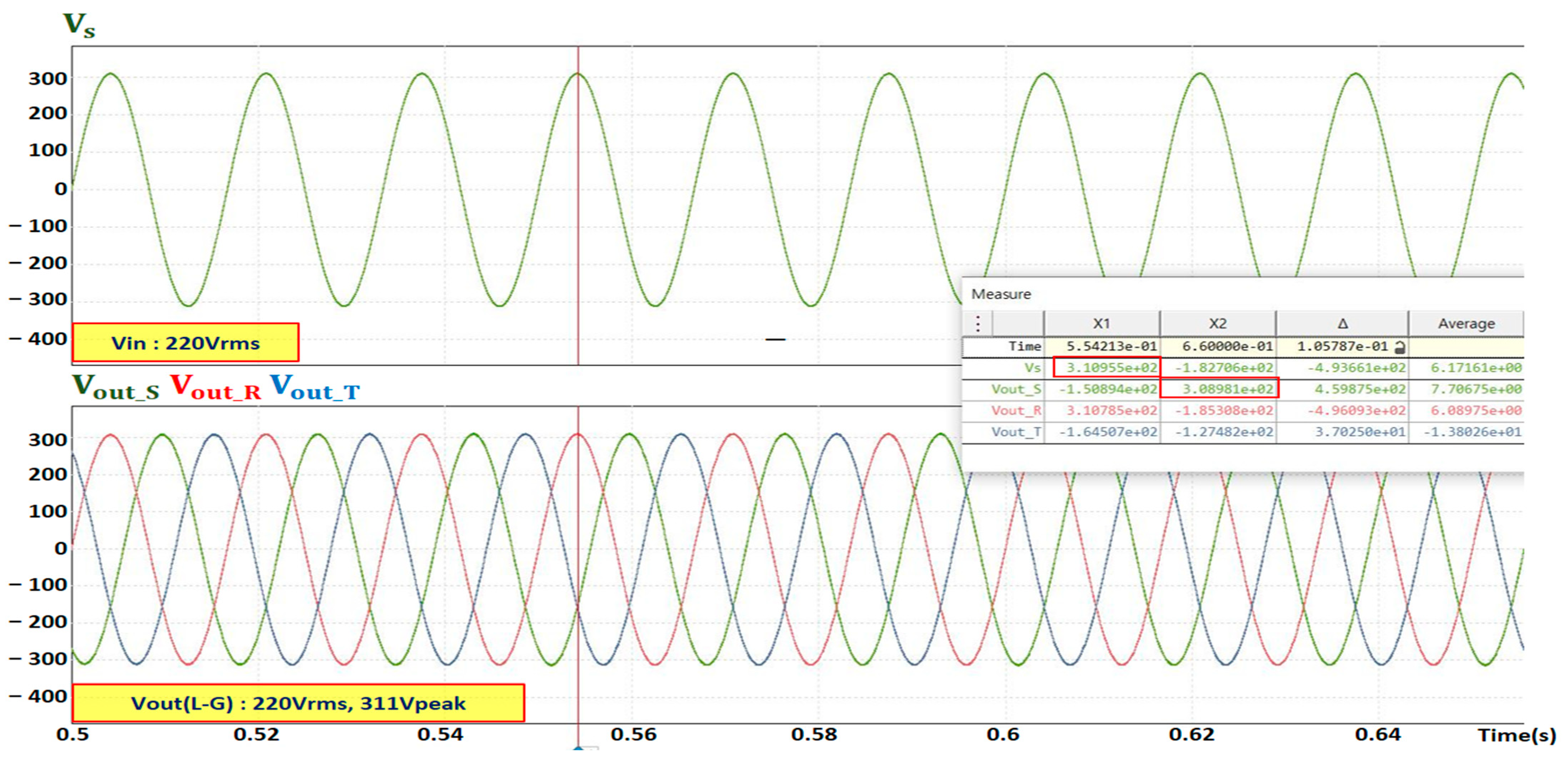
4.1. Result of Converting Three-Phase Voltage with Computer Simulation
- (A)
- Normal Load Conditions
- (B)
- DER Connection
- (C)
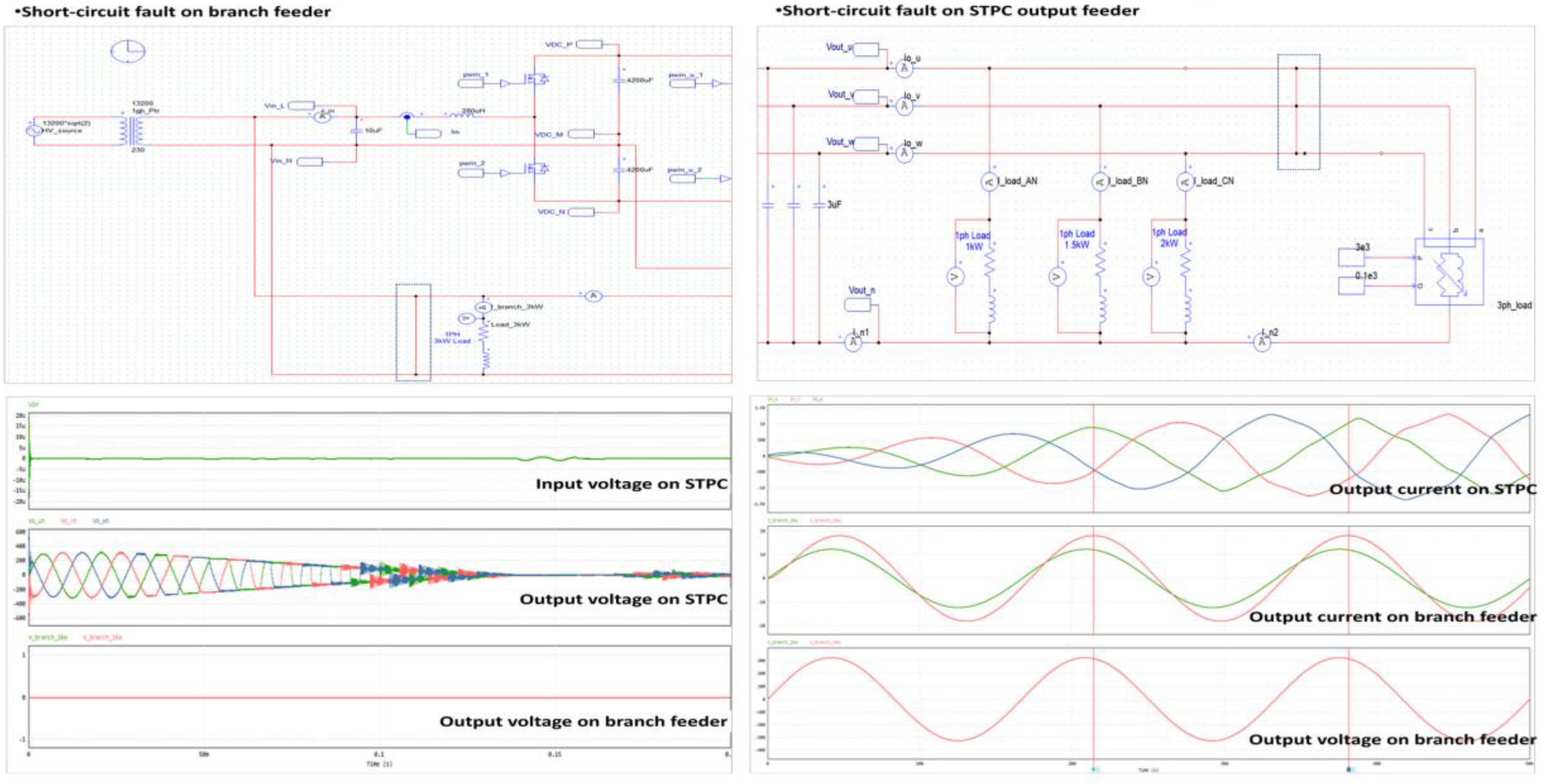
- Short-Circuit Fault
- (D)
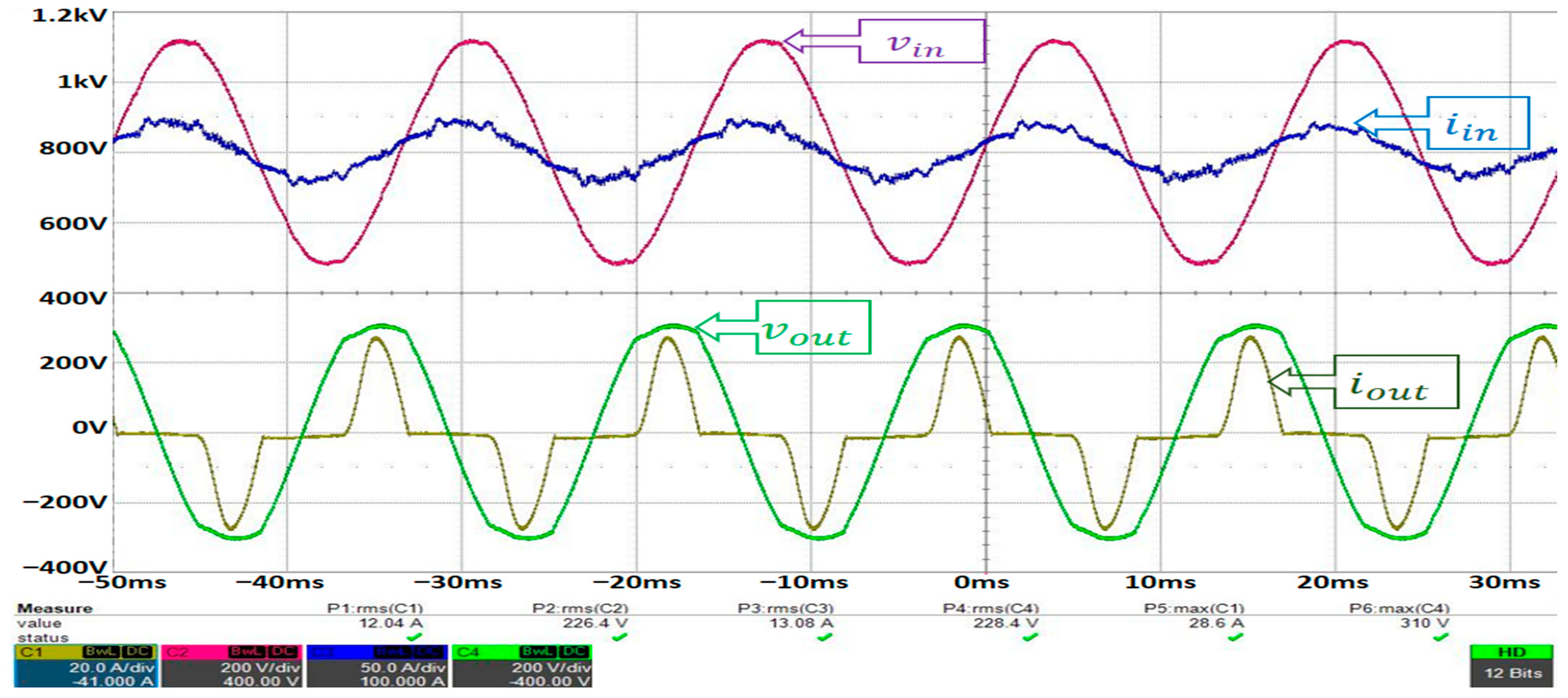
- Nonlinear Load Connection
4.2. Test Results of LV Loads
5. Discussion
5.1. Limitations of STPC
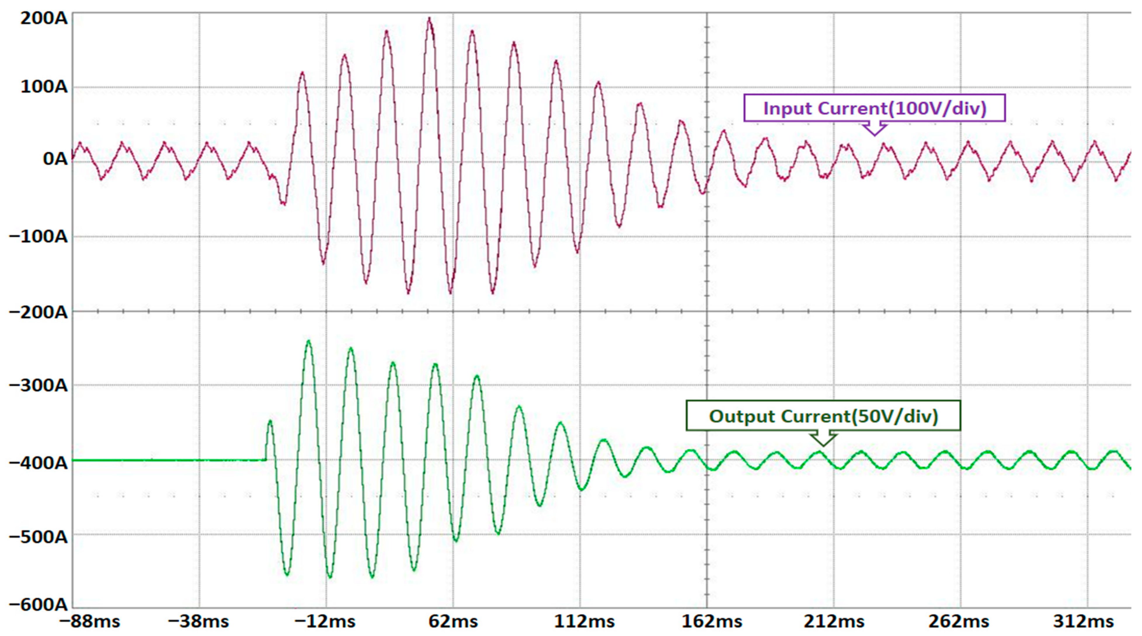
5.1.1. Inrush Current Sensitivity
5.1.2. Component Lifetime Concerns
5.1.3. Initial Cost and Development Overhead
5.2. Future Directions
5.2.1. Grid-Forming Inverter Function
5.2.2. Modular and Scalable Design
5.2.3. Application to LVDC Systems
6. Conclusions
Author Contributions
Funding
Institutional Review Board Statement
Informed Consent Statement
Data Availability Statement
Conflicts of Interest
Nomenclature
| PDS | Power Distribution System |
| LVDS | Low-Voltage Distribution Systems |
| STPC | Single-to-Three-Phase Converter |
| KEPCO | Korea Electric Power Corporation |
| PTS | Power Transmission System |
| DOL | Direct-On-Line |
| CP | Concrete Pole |
| PDE | Power Distribution Equipment |
| PQ | Power Quality |
| DER | Distributed Energy Resource |
| THD | Total Harmonic Distortion |
| ESS | Energy Storage System |
| PCS | Power Conditioning System |
| UPS | Uninterruptible Power Supply |
| STATCOM | Static Synchronous Compensator |
| P.TR | Pole-mounted Transformer |
| PI | Proportional Integral |
| PR | Proportional Resonant |
| RMS | Root Mean Square |
| MCCB | Molded Case Circuit Breaker |
| COS | Cut-Out Switch |
References
- Bayod-Rujula, A.A. Power electronics in Smart Grids. In Proceedings of the 2022 Congreso de Tecnología, Aprendizaje y Enseñanza de la Electrónica (XV Technologies Applied to Electronics Teaching Conference), Teruel, Spain, 29 June–1 July 2022; pp. 1–5. [Google Scholar]
- Blaabjerg, F.; Yang, Y.; Kim, K.A.; Rodriguez, J. Power electronics technology for large-scale renewable energy generation. IEEE 2023, 111, 335–355. [Google Scholar] [CrossRef]
- Mihalič, F.; Truntič, M.; Hren, A. Hardware-in-the-loop simulations: A historical overview of engineering challenges. Electronics 2022, 11, 2462. [Google Scholar] [CrossRef]
- Boroyevich, D.; Cvetković, I.; Dong, D.; Burgos, R.; Wang, F.; Lee, F. Future Electronic Power Distribution Systems. In Proceedings of the 12th International Conference on Optimization of Electrical and Electronic Equipment, Brasov, Romania, 20–22 May 2010. [Google Scholar]
- She, X.; Huang, A.Q.; Burgos, R. Review of solid-state transformer technologies and their application in power distribution systems. IEEE J. Emerg. Sel. Top. Power Electron. 2013, 1, 186–198. [Google Scholar] [CrossRef]
- Castelli Dezza, F.; Toscani, N.; Benvenuti, M.; Tagliaretti, R.; Agnetta, V.; Amatruda, M.; De Maria, S. Design and Simulation of a Novel Modular Converter-Transformer for AC/DC, DC/AC and DC/DC Operations. Energies 2024, 17, 6014. [Google Scholar] [CrossRef]
- He, X.; Shu, Z.; Peng, X.; Zhou, Q.; Zhou, Y.; Zhou, Q.; Gao, S. Advanced Cophase Traction Power Supply System Based on Three-Phase to Single-Phase Converter. IEEE Trans. Power Electron. 2014, 29, 5323–5333. [Google Scholar] [CrossRef]
- Ma, K.; Chen, W.; Liserre, M.; Blaabjerg, F. Power Controllability of a Three-Phase Converter With an Unbalanced AC Source. IEEE Trans. Power Electron. 2015, 30, 1591–1604. [Google Scholar] [CrossRef]
- Enjeti, P.N.; Rahman, A.; Jakkli, R. Economic single-phase to three-phase converter topologies for fixed and variable frequency output. IEEE Trans. Power Electron. 1993, 8, 329–335. [Google Scholar] [CrossRef]
- da Silva, S.A.O.; Negrao, F.A. Single-Phase to Three-Phase Unified Power Quality Conditioner Applied in Single-Wire Earth Return Electric Power Distribution Grids. IEEE Trans. Power Electron. 2018, 33, 3950–3960. [Google Scholar] [CrossRef]
- Hamidon, F.; Ali, I.M.; Khadari, M.; Abd Aziz, P.; Yunus, N.M. Design of single phase to three phase static power converter. In Proceedings of the 2014 4th International Conference on Engineering Technology and Technopreneuship (ICE2T), Kuala Lumpur, Malaysia, 27–29 August 2014; IEEE: Piscataway, NJ, USA, 2014; pp. 266–271. [Google Scholar]
- Matanov, N.; Angelov, I.; Stoev, P. A Study of Load Unbalance on Low Voltage Grid. In Proceedings of the 2024 16th Electrical Engineering Faculty Conference (BulEF), Varna, Bulgaria, 19–22 September 2024; IEEE: Piscataway, NJ, USA, 2024; pp. 1–5. [Google Scholar]
- Abinaya, M.; Senthilnathan, N.; Sabarimuthu, M. Harmonic compensation as ancillary service in PV inverter based residential distribution system. In Proceedings of the 2014 International Conference on Circuits, Power and Computing Technologies [ICCPCT-2014], Nagercoil, India, 20–21 March 2014; IEEE: Piscataway, NJ, USA, 2014; pp. 490–495. [Google Scholar]
- Duarte, C.H.; Schaeffer, R. Economic impacts of power electronics on electricity distribution systems. Energy 2010, 35, 4010–4015. [Google Scholar] [CrossRef]
- Infield, D.G.; Onions, P.; Simmons, A.D.; Smith, G.A. Power quality from multiple grid-connected single-phase inverters. IEEE Trans. Power Deliv. 2004, 19, 1983–1989. [Google Scholar] [CrossRef]
- Dong, H.; Yuan, S.; Han, Z.; Ding, X.; Ma, S.; Han, X. A Comprehensive Strategy for Power Quality Improvement of Multi-Inverter-Based Microgrid With Mixed Loads. IEEE Access 2018, 6, 30903–30916. [Google Scholar] [CrossRef]
- Cho, N.; Yoon, M.; Choi, S. Impact of transformer topology on short-circuit analysis in distribution systems with inverter-based distributed generations. Sustainability 2022, 14, 9781. [Google Scholar] [CrossRef]
- Yoon, M.; Cho, N.; Choi, S. Analysis of temporary overvoltage due to inverter-based distributed generation in networked distribution systems. Applied Energy 2023, 341, 121059. [Google Scholar] [CrossRef]
- Kim, J.; Choi, S. Robust and efficient WLS-based dynamic state estimation considering transformer core saturation. J. Frankl. Inst. 2020, 357, 12938–12959. [Google Scholar] [CrossRef]
- Pradipta, A.; Triwijaya, S.; Ridwan, M. Performance and Analysis of Indirect Torque Control-Based Three-Phase Induction Motor. ELKHA J. Tek. Elektro 2021, 13, 122–127. [Google Scholar] [CrossRef]
- Paez, M.A.; Salles, M.B.C.; Rahmann, C.; Grilo, A.P. Voltage support in industrial distribution systems in presence of induction generator-based wind turbines and large motors. Electr. Power Syst. Res. 2016, 140, 681–688. [Google Scholar] [CrossRef]
- Kim, T.-G.; An, C.-G.; Yi, J.; Won, C.-Y. Current Compensation Method in a Distribution System Based on a Four-Leg Inverter under Unbalanced Load Conditions Using an Artificial Neural Network. Energies 2024, 17, 1325. [Google Scholar] [CrossRef]
- Casolino, G.M.; Losi, A. Load Areas in Radial Unbalanced Distribution Systems. Energies 2019, 12, 3030. [Google Scholar] [CrossRef]
- Khan, A.; Ali, M. Three-Phase Load Balancing in Distribution Systems Using Load Sharing Technique. Eng. Proc. 2023, 46, 18. [Google Scholar]
- Möller, F.; Meyer, J. Probabilistic household load model for unbalance studies based on measurements. In Proceedings of the 2016 Electric Power Quality and Supply Reliability (PQ), Tallinn, Estonia, 29–31 August 2016; IEEE: Piscataway, NJ, USA, 2016; pp. 107–112. [Google Scholar]
- Habyarimana, M.; Musumpuka, R.; Dorrell, D. Mitigating In-rush Currents for Induction Motor Loads. In Proceedings of the 2021 IEEE Southern Power Electronics Conference (SPEC), Kigali, Rwanda, 6-9 December 2021; IEEE: Piscataway, NJ, USA, 2021; pp. 1–6. [Google Scholar]
- Dyussembekova, N.; Schütt, R.; Leiße, I.; Ralfs, B. Decision Process for Identifying Appropriate Devices for Power Transfer between Voltage Levels in Distribution Grids. Energies 2024, 17, 2158. [Google Scholar] [CrossRef]
- Du, W.; Tuffner, F.K.; Schneider, K.P.; Lasseter, R.H.; Xie, J.; Chen, Z.; Bhattarai, B. Modeling of Grid-Forming and Grid-Following Inverters for Dynamic Simulation of Large-Scale Distribution Systems. IEEE Trans. Power Deliv. 2021, 36, 2035–2045. [Google Scholar] [CrossRef]
- Unruh, P.; Nuschke, M.; Strauß, P.; Welck, F. Overview on grid-forming inverter control methods. Energies 2020, 13, 2589. [Google Scholar] [CrossRef]
- Zhang, L.; Zhu, Q.; Xiao, H. Topology, Control, and Applications of MMC with Embedded Energy Storage: A Brief Review. Electronics 2025, 14, 949. [Google Scholar] [CrossRef]
- Gwon, G.-H.; Kim, D.-U.; Oh, Y.-S.; Han, J.; Kim, C.-H. In Analysis of efficiency for AC and DC load in LVDC distribution system. In Proceedings of the 12th IET International Conference on Developments in Power System Protection (DPSP 2014), Copenhagen, Denmark, 31 March–3 April 2014; IET: London, UK, 2014; p. 12.18. [Google Scholar]
- Kim, J.-Y.; Kim, H.-S.; Baek, J.-W.; Jeong, D.-K. Analysis of effective three-level neutral point clamped converter system for the bipolar LVDC distribution. Electronics 2019, 8, 691. [Google Scholar] [CrossRef]


| Feature | Ref. [9] | Ref. [10] | This Paper |
|---|---|---|---|
| Input Type | Single-phase AC | Single-wire earth return | Single-phase 220 V AC |
| DC Link Usage | No | Yes | Yes, 750 V DC link |
| Control Strategy | Passive rectification + inverter | Unified PQ controller | PI + PR control with notch filter |
| Validation Method | Simulation + partial experiment | Simulation | Simulation + field experiment |
| Load Conditions Tested | Fixed frequency motor loads | Unbalanced voltage systems | Nonlinear, unbalanced, and motor loads |
| Target System | Small industrial systems | Rural electrification | Low-voltage distribution system |
| Semiconductor Devices | Si-based devices | IGBT | SiC-MOSFET |
| Application Focus | Economic converter topology | PQ compensation in SWER | Three-phase supply for LVDS with PQ assurance |
| PICOT | Research Questions |
|---|---|
| Population | ① A substantial financial investment is required for constructing power facilities to supply a three-phase voltage (challenge). ② Target population: Phase conversion equipment, PDS, fault analysis (target population). |
| Intervention | Unbalanced loads, nonlinear loads, and motor load. |
| Comparison/Control | Maintaining the standard voltage range, generating three-phase voltage (expected outcome). |
| Timeframe | ① Review of research. ② Analysis of PDS challenges. ③ Assertive hypothesis. ④ Derivation of results. |
| Methods | Strength | Weakness |
|---|---|---|
| Static Phase | Simple circuit configuration Low implementation cost | Unstable performance under heavy load conditions Limited power capacity Dedicated transformer required |
| Rotary Phase | High reliability Resistant to load changes | Loudness, noise Maintenance Dedicated transformer required |
| Electronic Phase | High-quality three-phase voltage output Three-phase voltage balance High conversion efficiency Voltage stabilization | High initial cost Complex electronic circuits |
| Converter (Input) | Inverter (Output) | |
|---|---|---|
| Applied topology | Single-phase Half-Bridge | Three-phase Full-Bridge |
| Element | SiC-MOSFET | SiC-MOSFET |
| Switching frequency | 30 kHz | 30 kHz |
| PWM | SPWM | SPWM |
| Method of control | DQ PI+PR | DQ PI+PR |
| VTHD-R | VTHD-S | VTHD-T | ITHD-R | ITHD-S | ITHD-T | |
|---|---|---|---|---|---|---|
| THD | 0.66% | 4.62% | 0.33% | 8.32% | 92.63% | 11.10% |
| HP | Rated Power | Pole | Rated Speed | Efficiency | Power Factor | Rated Current | Inrush Current | ||
|---|---|---|---|---|---|---|---|---|---|
| 220 V | 380 V | 220 V | 380 V | ||||||
| 1 | 0.75 kW | 2 | 3400 rpm | 73% | 84 | 3.2 | 1.9 | 19.3 | 11.1 |
| 4 | 1710 rpm | 74% | 77 | 3.5 | 2.0 | 20.7 | 12.0 | ||
| 2 | 1.5 kW | 2 | 3400 rpm | 77% | 81 | 6.3 | 3.7 | 37.9 | 21.9 |
| 4 | 1720 rpm | 80% | 77 | 6.4 | 3.7 | 38.3 | 22.2 | ||
| 3 | 2.2 kW | 2 | 3420 rpm | 80% | 85 | 8.5 | 4.9 | 50.9 | 29.5 |
| 4 | 1730 rpm | 82% | 81 | 8.7 | 5.0 | 52.2 | 30.2 | ||
| Comparison Criteria | Conventional Method | Proposed STPC |
|---|---|---|
| Installation Method | Line extension + transformer installation | Modular installation at load site |
| Conversion Efficiency | High (typically >98%) | Moderate (>96%) |
| Voltage Regulation | Passive, no regulation capability | Stable regulation of the output voltage |
| Maintenance Complexity | Low (simple structure) | Moderate (semiconductor components, cooling) |
| Initial Installation Cost | High (due to line and transformer construction) | Lower |
| MTBF (Expected Reliability) | Very high (few active components) | Moderate (semiconductor aging, fan/capacitor life) |
| Harmonic Mitigation | Not available | Built-in through filters and PR controller |
Disclaimer/Publisher’s Note: The statements, opinions and data contained in all publications are solely those of the individual author(s) and contributor(s) and not of MDPI and/or the editor(s). MDPI and/or the editor(s) disclaim responsibility for any injury to people or property resulting from any ideas, methods, instructions or products referred to in the content. |
© 2025 by the authors. Licensee MDPI, Basel, Switzerland. This article is an open access article distributed under the terms and conditions of the Creative Commons Attribution (CC BY) license (https://creativecommons.org/licenses/by/4.0/).
Share and Cite
Shin, B.; Kim, C.; Lee, H.; Choi, S. Design and Validation of a SiC-Based Single-to-Three-Phase Converter for Low-Voltage Distribution Systems. Appl. Sci. 2025, 15, 5590. https://doi.org/10.3390/app15105590
Shin B, Kim C, Lee H, Choi S. Design and Validation of a SiC-Based Single-to-Three-Phase Converter for Low-Voltage Distribution Systems. Applied Sciences. 2025; 15(10):5590. https://doi.org/10.3390/app15105590
Chicago/Turabian StyleShin, Boohyun, Changhwan Kim, Hyeseon Lee, and Sungyun Choi. 2025. "Design and Validation of a SiC-Based Single-to-Three-Phase Converter for Low-Voltage Distribution Systems" Applied Sciences 15, no. 10: 5590. https://doi.org/10.3390/app15105590
APA StyleShin, B., Kim, C., Lee, H., & Choi, S. (2025). Design and Validation of a SiC-Based Single-to-Three-Phase Converter for Low-Voltage Distribution Systems. Applied Sciences, 15(10), 5590. https://doi.org/10.3390/app15105590