Abstract
A novel single-layer multi-coupling 3D frequency-selective surface featuring high selectivity and a 3D dual-band frequency-selective surface (3D-DBFSS) is presented in this paper. By incorporating three different coupling gaps within each unit cell, the design achieves two distinct passbands with wide bandwidths and steep transition edges. For the first passband, the −3 dB bandwidth ranges from the lower cutoff frequency of 9.9 GHz to the upper cutoff frequency of 15.2 GHz, yielding a bandwidth (BWL3dB) of 5.3 GHz. For the second passband, the −3 dB bandwidth extends from 22 GHz to 26 GHz, providing a bandwidth (BWU3dB) of 4 GHz. The structure exhibits eight transmission poles and four transmission zeros within a single layer, enhancing its selectivity. The simulation results indicate that the dual passbands are centered at 12 GHz and 24 GHz, respectively, with bandwidths sufficient for practical applications. The proposed frequency-selective surface demonstrates a low insertion loss of just 0.8 dB, which is significantly lower compared to most reported dual-band FSS designs. Furthermore, the thickness of the 3D-DBFSS is only one-third of the wavelength in free space, making it considerably thinner than other 3D-FSS structures operating in the same frequency range. The proposed design also ensures stable performance over a wide range of incident angles, which is crucial for practical deployment. Additionally, the overall size of the unit cell of the frequency-selective surface is 4 × 4 × 10.8 m3. The structure is easy to fabricate, which contributes to its potential for cost-effective mass production. Overall, the 3D-DBFSS offers high frequency selectivity, effective bandpass performance, and strong suppression in the stopband region.
1. Introduction
A frequency-selective surface (FSS) [1] is a two-dimensional array structure consisting of periodically arranged metal patches and slots [2]. Over the past several decades, FSSs have been extensively investigated for their capabilities in filtering electromagnetic waves and have found applications in radar design [3,4,5,6,7], radar cross-section (RCS) reduction [8], industrial applications [9,10], electromagnetic shielding [11], and various scientific and medical fields. The key performance indicators for FSSs include a wide passband, steep transition edges, and insensitivity to polarization [12] and angles of incident waves.
Traditional two-dimensional FSS (2D-FSS) structures, which are typically composed of single or multiple layers of metal patches, often struggle to simultaneously achieve all of the desired performance characteristics, such as wide passbands and steep transition edges. To address these limitations, an additional connection structure can be introduced between the layers, resulting in the formation of a three-dimensional FSS (3D-FSS). This 3D configuration has gained significant attention due to the additional degrees of freedom it provides in the design process, enabling enhanced performance characteristics. Specifically, 3D-FSS designs are capable of achieving ultra-wide passbands, insensitivity to both angle and polarization, flat in-band filter responses, steep edges, and wide out-of-band rejection.
Existing 3D-FSS designs are primarily based on several methodologies, including the waveguide principle, equivalent circuit modeling, and effective medium concepts. In these designs, inter-layer structures serve a variety of roles, such as acting as waveguide walls for electromagnetic confinement, providing resonant paths as transmission lines, or functioning as materials with left-handed properties to achieve a desired dielectric constant. These inter-layer structures are typically implemented using periodic arrays of microstrip lines, metallic plates, via holes, or resonant metallic lines, contributing to enhanced electromagnetic performance.
With the rapid advancement of wireless communication technologies, single-frequency communication equipment has become increasingly insufficient due to the limited spectrum resources available. Consequently, researchers have developed wide passband FSSs with superior performance to address these challenges [13,14,15]. Furthermore, enabling devices to operate across multiple frequency bands has become a major research focus, resulting in significant interest in dual-frequency and multi-frequency FSS designs [16,17,18,19,20]. Currently, multiple passbands are largely achieved through the use of multilayer FSS designs; however, these approaches often suffer from narrow bandwidths and insufficiently steep edges, limiting their practical utility.
The miniaturized conical FSS designed in reference [21] exhibits excellent angular stability (80° in planar state and 75° in conical state) and dual-polarization compatibility in both planar and conical configurations. This work fills the research gap in conical bandpass FSS and provides a new scheme for the conformal design of radomes. The consistency between the measured and simulated results verifies its engineering feasibility and highlights its significant practical application value.
Ref. [22] proposes a design of broadband dual-polarization switchable active frequency-selective surface (AFSS) based on PIN diodes. By controlling the bias states of PIN diodes, dynamic switching between the reflection mode and transmission mode is achieved. The design features a wide bandwidth and dual-polarization characteristics, showing application potential in stealth technology and other fields.
In this work, a dual-passband 3D-FSS unit cell with multiple coupling structures is proposed. In the second part of this paper, the design and simulation of a dual-passband 3D frequency-selective surface (3D-FSS) unit cell with multiple coupling structures are carried out. In the third part, a 3D-DBFSS prototype composed of 10 × 8 units is fabricated. Due to the limitations of 3D printing technology, there are differences between the actual fabrication parameters and the simulation parameters. The equipment, environment, and steps for measurement are introduced. The simulation and measurement results are compared, and the reasons for the differences are analyzed. Finally, the design innovation points of the 3D-DBFSS are summarized, and its excellent characteristics, such as steep edge response, insensitivity to the incident angle, and polarization, are generalized. The advantages in terms of bandwidth and frequency selectivity compared with other dual-band FSS designs are emphasized, and the applicability and high performance of this design in practical dual-band communication applications are explained.
2. Design Principle
2.1. Design Configuration
This study introduces a novel single-layer, dual-bandpass, electromagnetic 3D frequency-selective surface (FSS) designed to regulate the transmission of incident electromagnetic waves across two passbands. By employing an orthogonal arrangement of metal patches with distinct slit structures, a 3D unit capable of bandpass filtering is achieved, as reported in [21]. The proposed FSS consists of a unit cell supported by a dielectric substrate with a relative permittivity of 4.3 and a loss tangent of 0.02. The structure is formed by two identical surface waveguides oriented perpendicularly to each other. Figure 1 presents the configuration of the 3D FSS unit cell, while Table 1 summarizes the final dimensions of the unit cell.
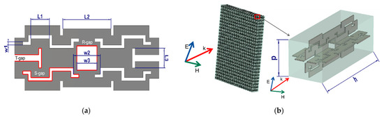
Figure 1.
The 3D-FSS unit cell model. (a) Three kinds of gaps. (b) Perspective view of full structure and unit cell.

Table 1.
Dimensions of the proposed FSS unit cell.
In the design of the planar unit cell, the S-gap, T-gap, and R-gap are incorporated into the unit cell of the 3D FSS, as shown in Figure 1a. The S-gap primarily influences the lower-frequency band by extending the current path, while the T-gap and R-gap are tailored to adjust the higher-frequency band, providing multiple resonances that contribute to the dual-band response. This strategic combination allows for a compact unit cell design with efficient use of space and material, maintaining a thin profile of approximately one-third of the free-space wavelength.
When designing the 3D unit cell, the planar unit cells are orthogonally configured. The use of two perpendicular surface waveguides further enhances the filtering capability, enabling the unit cell to support dual-band functionality without significant performance degradation. The orthogonal configuration of the metal patches, along with the introduction of multiple gap structures, allows the FSS to achieve selective transmission characteristics at multiple resonant frequencies. The combination of different gap structures provides multiple degrees of freedom in designing the resonant characteristics, enhancing both the selectivity and the miniaturization of the FSS. This design can be effectively utilized in applications where compact, multi-band electromagnetic filters are required. The chosen substrate, with a relative permittivity of 4.3, ensures adequate support for the surface waveguides while maintaining low loss characteristics.
Furthermore, the flexibility of the design allows for easy adaptation to different frequency ranges by scaling the dimensions of the unit cell and the gap structures. This scalability makes the 3D-FSS a versatile solution for a wide range of electromagnetic filtering applications, where space constraints and multi-band functionality are critical requirements. The innovative use of gap structures, combined with the orthogonal waveguide configuration, represents a significant advancement in the development of compact and efficient frequency-selective surfaces
2.2. Simulation and Analysis
To elucidate the underlying physical mechanisms responsible for the bandpass behavior, the differences between wave transmission in the passband and stopband were analyzed. The simulation was conducted using the numerical simulation software, with periodic boundary conditions along the x and y directions and open conditions along the z direction. The simulations were performed using the Finite Element Method (FEM) algorithm, providing a comprehensive understanding of the electromagnetic behavior of the designed 3D-FSS.
Figure 2 presents the simulated S-parameter results of the proposed frequency-selective surface (FSS). The first passband is located between 10 GHz and 14 GHz, containing five transmission poles at 10.6 GHz, 11.27 GHz, 13.7 GHz, 14.83 GHz, and 15.1 GHz. The second passband lies between 22 GHz and 25.7 GHz, with three transmission poles at 23.2 GHz, 25.13 GHz, and 25.35 GHz. As illustrated in Figure 2, the designed FSS features four transmission zeros: three are located between the two passbands at 15.45 GHz, 16.17 GHz, and 17.571 GHz, while the fourth is at 26.1 GHz, beyond the upper passband. The transmission zeros near the passbands enhance the selectivity of the FSS. The passband of the proposed 3D-DBFSS exhibits very low insertion loss, with variations of less than 0.8 dB, ensuring a flat frequency response.
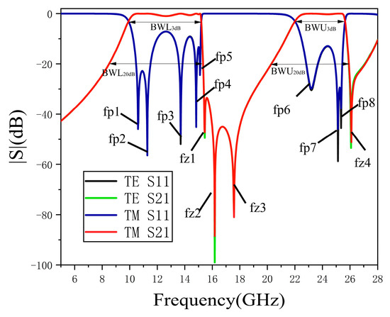
Figure 2.
The S-parameters of proposed 3D-DBFSS.
From Figure 2, it can also be observed that the designed FSS demonstrates distinct transmission characteristics for both TE and TM polarizations. The S-parameters (|S11| and |S21|) for TE and TM polarizations are plotted, showing consistent performance across the frequency bands. For TE polarization, the reflection coefficient (S11) maintains a high level of rejection in the stopbands, while the transmission coefficient (S21) shows sharp peaks at the transmission poles (fp1 to fp8). For TM polarization, a similar behavior is observed, with distinct transmission poles and transmission zeros (fz1 to fz4) that contribute to the overall selectivity. The presence of multiple transmission poles and zeros enhances the ability of the FSS to filter out unwanted frequencies effectively, thereby improving the performance of the proposed structure.
To evaluate the frequency selectivity of the FSS, a technical index (K) is defined. This index quantifies the sharpness of the frequency response at the cutoff frequencies, indicating the filter’s ability to suppress unwanted signals outside the passband. The index K is defined as the ratio of the −3 dB bandwidth to the −20 dB bandwidth.
K = BW3dB/BW20dB
For the first passband, the −3 dB bandwidth ranges from the lower cutoff frequency of 9.9 GHz to the upper cutoff frequency of 15.2 GHz, yielding a bandwidth (BWL3dB) of 5.3 GHz. The −20 dB bandwidth (BWL20dB) for the same passband is 6.4 GHz. Thus, the sharpness index (KL), defined as the ratio of BWL3dB to BWL20dB, is 82.8%. For the second passband, the −3 dB bandwidth extends from 22 GHz to 26 GHz, providing a bandwidth (BWU3dB) of 4 GHz. The sharpness index for the second passband (KU) is calculated as 80.2%.
It is well understood that increasing the number of transmission poles enhances the passband characteristics by reducing insertion loss and widening the bandwidth. In this design, the five transmission poles (fp1–fp5) within the first passband facilitate a broad passband between approximately 10.6 GHz and 15.1 GHz. A detailed examination of the current transmission paths at frequencies of 10.6 GHz and 15.1 GHz, as shown in Figure 3, reveals significant differences in the current loops. Through specific structural combinations, the three gap structures depicted in Figure 1 form multiple coupling paths to direct incident waves through the FSS.
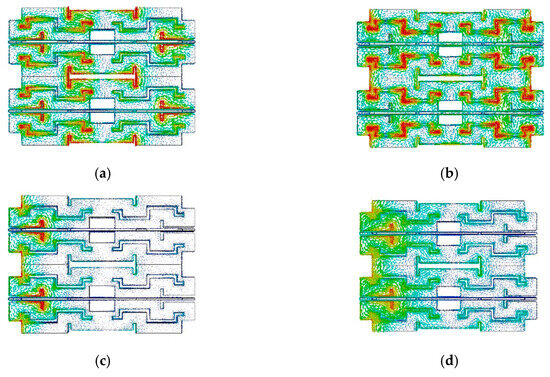
Figure 3.
The coupled path of current transmission at the transmission pole. (a) fp1 = 10.6 GHz. (b) fp5 = 15.1 GHz and transmission zero. (c) fz2 = 16.17 GHz. (d) fz3 = 17.57 GHz.
Figure 3 illustrates the coupled path of current transmission at the transmission poles and zeros. As shown in Figure 3a,b, the current distribution at the transmission poles (fp1 at 10.6 GHz and fp5 at 15.1 GHz) reveals that the current flows through the S-gap and T-gap in different configurations, facilitating effective energy transfer. On the other hand, Figure 3c,d show the current distribution at the transmission zeros (fz2 at 16.17 GHz and fz3 at 17.57 GHz), where the surface current distribution changes significantly. At these transmission zeros, there is no effective coupling path, resulting in most of the incident wave energy being either reflected or absorbed. This illustrates the distinct behavior of the FSS at transmission poles and zeros, which is critical for achieving the desired filtering characteristics.
Furthermore, the analysis of the surface current paths highlights the importance of coupling mechanisms in determining the frequency response of the FSS. The coupling between different gap structures creates multiple resonant modes, which directly influence the formation of transmission poles and zeros. By effectively managing these coupling paths, the FSS achieves a high level of selectivity and control over the transmission characteristics. The coupling behavior not only contributes to the desired dual-band performance but also ensures that the structure maintains a compact form factor without compromising functionality.
The effectiveness of the coupling paths can also be observed in the differences between the transmission poles and zeros. While transmission poles are characterized by strong coupling that facilitates efficient energy transfer, transmission zeros represent frequencies where the coupling is insufficient, leading to energy reflection or absorption. The ability to accurately control these characteristics is key to designing an FSS with excellent frequency selectivity and stability, as demonstrated by the proposed 3D-DBFSS. The combination of different coupling paths, as shown in Figure 3, allows the FSS to maintain its performance across a wide range of frequencies, making it suitable for practical applications where dual-band frequency filtering is required.
The transmission characteristics for incidence angles of up to 30° are illustrated in Figure 4. As depicted in Figure 4a, the first passband exhibits insensitivity to variations in the incidence angle for TE polarization, showing consistent performance for angles from 0° to 30°. However, the higher-frequency passband shows a slight ripple as the incidence angle increases, and frequency shifts of approximately 0.1% and 0.3% are observed in the two passbands, respectively. Similarly, Figure 4b presents the results for TM polarization, where the frequency shifts in the two passbands are less than 0.1% as the incidence angle varies up to 30°. These findings demonstrate that the proposed 3D-DBFSS maintains good angular stability for both TE and TM polarizations under oblique incidence angles of up to 30°.
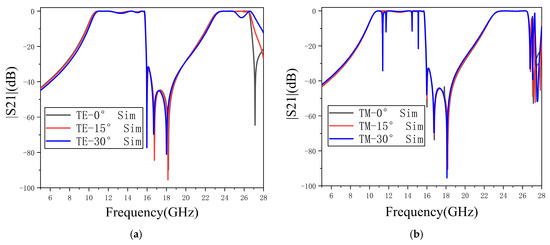
Figure 4.
The variation of the transmission coefficient. (a) Transmission coefficient of TE wave varying from 0° to 30°. (b) Transmission coefficient of TM wave varying from 0° to 30°.
It is also noteworthy that, by coupling different types of gaps, the monolayer 3D-DBFSS achieves eight transmission poles within the two passbands, without the need for increasing the number of layers to enhance the transmission zero points. This innovative design ensures that the proposed FSS is significantly thinner than most reported 3D-FSS structures, making it more efficient for practical implementation.
In addition to demonstrating stability with respect to the incidence angle and polarization, a functional FSS for practical applications must also possess strong frequency selectivity and adequate bandwidth across both passbands.
3. Fabrication and Measurement
To validate the effectiveness of the proposed design, a prototype of the DBFSS, consisting of 10 × 8 elements, was fabricated with a total size of 96 × 88 × 21 mm2. During the manufacturing process, due to the limitations of the 3D printing process and cost constraints, we encountered significant difficulties in realizing a structure with smaller dimensions. To solve this problem, we removed the substrate and enlarged the structure. The complete structure and measurement setup are illustrated in Figure 5. The parameters of the fabricated model used for the measurement are provided in Table 2. Due to the fabrication limitation, the dielectric material was removed from the 3D-DBFSS for the experimental setup. The same parameters and conditions were used in the simulation for comparative purposes.
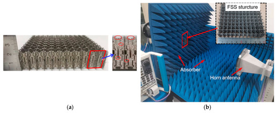
Figure 5.
Protype of the 3D-DBFSS and measurement setup. (a) 3D-DBFSS side view and local details. (b) Test setup side view.
Table 2.
Parameters of the model used in the measurement.
The 3D-DBFSS was enclosed with absorbers, and a vector network analyzer (VNA) was employed to minimize unwanted transmissions from the edges of the DBFSS structure. For the measurement process, two horn antennas were used in a microwave chamber—one serving as the transmitter and the other as the receiver. The measurement procedure was conducted in two steps: in the first step, transmission coefficients were measured without the DBFSS structure; in the second step, the measurements were taken with the DBFSS in place. The results were then normalized with respect to the first step’s measurements.
To evaluate the transmission coefficients at oblique incidence for TE mode, the holder containing the DBFSS was rotated horizontally. By rotating the holder 90° along the vertical axis, the TE mode was switched to the TM mode, and the transmittance was measured again at various incidence angles. The measurements, taken with and without the DBFSS, were used to normalize the response, and the transmission coefficients for obliquely incident dual-polarized waves are presented in Figure 6 and Figure 7.
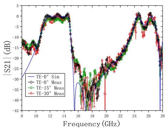
Figure 6.
Simulated and measured transmission coefficients at oblique incidence of TE polarized waves.
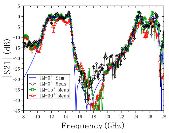
Figure 7.
Simulated and measured transmission coefficients at oblique incidence of TM polarized waves.
Some discrepancies between the simulated and measured results were observed. These deviations can be primarily attributed to two factors. First, the presence of metal particles and surface defects introduced by the 3D printing process resulted in significant disturbances to the surface current. As shown in Figure 5a, the surface of the fabricated structure is rough and contains numerous defects, which contribute to performance variations. Second, the diffraction effects caused by the finite size of the DBFSS structure further contributed to the observed differences. Due to the constraints of the available 3D printing equipment, the overall size of the front face of the structure was limited to 96 × 88 mm2, which exacerbated the edge diffraction effects on the transmission coefficient curve. Despite these challenges, a strong correlation between the simulated and measured results was still observed, demonstrating good agreement overall.
To assess the effectiveness of the proposed 3D-DBFSS, the frequency selection characteristics and bandwidth are evaluated and compared with those of other dual-band bandpass FSS designs reported in the literature, as shown in Table 3.
Table 3.
Comparison of the existing dual-band bandpass designs in the literature.
The comparison in Table 3 reveals that the proposed 3D-DBFSS achieves a superior frequency selectivity, with bandwidths of 5.3 GHz for the lower passband and 4.0 GHz for the upper passband, which are sufficient to meet practical application requirements. Moreover, the selection characteristic indices, KL and KU, which quantify the ratio of the −3 dB bandwidth to the −20 dB bandwidth, are 82.8% and 80.2%, respectively. These values are significantly higher compared to those of the existing designs summarized in Table 3, underscoring the enhanced selectivity of the proposed FSS. For instance, the bandwidths of previous designs range from 0.42 GHz to 6.4 GHz for the lower passband and from 1.32 GHz to 17.5 GHz for the upper passband, whereas the selection indices for these designs vary from 11.4% to 69%.
These results collectively demonstrate that the proposed 3D-DBFSS offers an effective solution with good angular stability, superior frequency selectivity, and sufficient bandwidth, positioning it as a competitive option for practical applications requiring dual-band bandpass filtering.
4. Conclusions
In this work, a 3D-DBFSS is proposed, along with an innovative design concept. The design incorporates three distinct gaps within a single-layer structure, which interact through different coupling mechanisms to form a multi-mode resonant cavity. This resonant configuration results in eight transmission poles and three transmission zeros, providing excellent performance while significantly reducing the overall thickness of the FSS.
The proposed 3D-DBFSS exhibits several desirable characteristics, including steep edge responses, as well as insensitivity to variations in incidence angle and polarization. Compared to other dual-band FSS designs, the proposed structure has several advantages. Firstly, it provides sufficient bandwidths for both passbands, which are 5.3 GHz and 4 GHz, respectively—adequate for practical applications. Secondly, the selection index K, which quantifies the frequency selectivity, is significantly higher than those of previously surveyed designs. By employing multiple gaps in a single unit cell, the design achieves multiple transmission poles and zeros, providing a novel approach to reducing the thickness of the FSS.
Furthermore, compared to previous designs, the proposed 3D-DBFSS effectively meets the requirements for dual-frequency communication, featuring dual-wideband operation, sharp roll-off characteristics, and a reduced radar cross-section (RCS). These attributes make the proposed FSS highly suitable for practical dual-band communication applications, offering enhanced performance in terms of bandwidth, selectivity, and overall structural efficiency.
Author Contributions
Conceptualization, X.F., R.F., Z.W., N.L., P.O. and M.B.; Methodology, X.F., R.F., Z.W., N.L., P.O. and M.B.; Software, X.F., R.F., Z.W., N.L., P.O. and M.B.; Validation, X.F., R.F., Z.W., N.L., P.O. and M.B.; Formal analysis, X.F., R.F., Z.W., N.L., P.O. and M.B.; Investigation, X.F., R.F., Z.W., N.L., P.O. and M.B.; Resources, X.F., R.F., Z.W., N.L., P.O. and M.B.; Data curation, X.F., R.F., Z.W., N.L., P.O. and M.B.; Writing—original draft, X.F., R.F., Z.W., N.L., P.O. and M.B.; Writing—review & editing, X.F., R.F., Z.W., N.L., P.O. and M.B.; Visualization, X.F., R.F., Z.W., N.L., P.O. and M.B.; Supervision, X.F., R.F., Z.W., N.L., P.O. and M.B.; Project administration, X.F., R.F., Z.W., N.L., P.O. and M.B.; Funding acquisition, X.F., R.F., Z.W., N.L., P.O. and M.B. All authors have read and agreed to the published version of the manuscript.
Funding
This research was funded by Beiiing Naturalscience Foundation grant number L243029.
Institutional Review Board Statement
Not applicable.
Informed Consent Statement
Not applicable.
Data Availability Statement
The original contributions presented in this study are included in the article. Further inquiries can be directed to the corresponding author.
Conflicts of Interest
The authors declare no conflict of interest.
References
- Munk, B.A. Frequency Selective Surfaces: Theory and Design; Wiley: Hoboken, NJ, USA, 2000. [Google Scholar]
- Iskander, M.F.; Kim, W.; Bell, J.; Celik, N.; Yun, Z.; Youn, H. Antenna arrays technologies for advanced wireless systems. In Proceedings of the 2009 IEEE International Conference on Microwaves, Communications, Antennas and Electronics Systems, Tel Aviv, Israel, 9–11 November 2009; pp. 1–4. [Google Scholar]
- Ferreira, D.; Cuinas, I.; Caldeirinha, R.F.S.; Fernandes, T.R. 3-D Mechanically Tunable Square Slot FSS. IEEE Trans. Antennas Propag. 2017, 65, 242–250. [Google Scholar] [CrossRef]
- Costa, F.; Monorchio, A. A Frequency Selective Radome with Wideband Absorbing Properties. IEEE Trans. Antennas Propag. 2012, 60, 2740–2747. [Google Scholar] [CrossRef]
- Omar, A.A.; Shen, Z. Thin 3-D Bandpass Frequency-Selective Structure Based on Folded Substrate for Conformal Radome Applications. IEEE Trans. Antennas Propag. 2019, 67, 282–290. [Google Scholar] [CrossRef]
- Liu, N.; Sheng, X.; Zhang, C.; Guo, D. Design of Frequency Selective Surface Structure with High Angular Stability for Radome Application. Antennas Wirel. Propag. Lett. 2018, 17, 138–141. [Google Scholar] [CrossRef]
- Liu, L.; Yang, C.; Cao, Q.; Li, H.; Wang, Y. Smart-skins for radome using active frequency selective surface. In Proceedings of the 2016 IEEE International Workshop on Electromagnetics: Applications and Student Innovation Competition (iWEM), Nanjing, China, 16–18 May 2016; pp. 1–3. [Google Scholar]
- Huang, C.; Ji, C.; Wu, X.; Song, J.; Luo, X. Combining FSS and EBG Surfaces for High-Efficiency Transmission and Low-Scattering Properties. IEEE Trans. Antennas Propag. 2018, 66, 1628–1632. [Google Scholar] [CrossRef]
- Fakhte, R.; Aryanian, I. Compact Fabry–Perot Antenna with Wide 3 dB Axial Ratio Bandwidth Based on FSS and AMC Structures. Antennas Wirel. Propag. Lett. 2020, 19, 1326–1330. [Google Scholar] [CrossRef]
- Liang, J.; Cao, Q.; Wang, Y.; Wan, Z. A Multifunctional and Miniaturized Flexible Active Frequency Selective Surface. Antennas Wirel. Propag. Lett. 2021, 20, 2549–2553. [Google Scholar] [CrossRef]
- Li, H.; Cao, Q.; Wang, Y. A Novel 2-B Multifunctional Active Frequency Selective Surface for LTE-2.1 GHz. IEEE Trans. Antennas Propag. 2017, 65, 3084–3092. [Google Scholar] [CrossRef]
- Ashvanth, B.; Partibane, B.; Alsath, M.G.N. An Ultraminiaturized Frequency Selective Surface with Angular and Polarization Stability. Antennas Wirel. Propag. Lett. 2022, 21, 114–118. [Google Scholar] [CrossRef]
- Li, H.; Li, B.; Zhu, L. Wideband Bandpass Frequency-Selective Structures on Stacked Slotline Resonators: Proposal and Synthetic Design. IEEE Trans. Antennas Propag. 2020, 68, 7068–7078. [Google Scholar] [CrossRef]
- Li, B.; Shen, Z. Bandpass Frequency Selective Structure with Wideband Spurious Rejection. Antennas Wirel. Propag. Lett. 2014, 13, 145–148. [Google Scholar]
- Lalbakhsh, A.; Afzal, M.U.; Esselle, K.P.; Smith, S.L. All-Metal Wideband Frequency-Selective Surface Bandpass Filter for TE and TM Polarizations. IEEE Trans. Antennas Propag. 2022, 70, 2790–2800. [Google Scholar] [CrossRef]
- Jia, F.; Liao, S.; Xue, Q. A Dual-Band Dual-Polarized Antenna Array Arrangement and Its Application for Base Station Antennas. Antennas Wirel. Propag. Lett. 2020, 19, 972–976. [Google Scholar] [CrossRef]
- Liu, Y.; Wang, S.; Li, N.; Wang, J.-B.; Zhao, J. A Compact Dual-Band Dual-Polarized Antenna with Filtering Structures for Sub-6 GHz Base Station Applications. Antennas Wirel. Propag. Lett. 2018, 17, 1764–1768. [Google Scholar] [CrossRef]
- Zhao, Z.; Yang, Y.; Huo, H.; Li, J.; Chen, J.; Zhang, A. A novel dual-band frequency selective surface with close band spacing at ka-band. In Proceedings of the 2017 Sixth Asia-Pacific Conference on Antennas and Propagation (APCAP), Xi’an, China, 16–19 October 2017; pp. 1–3. [Google Scholar]
- Shah, G.; Cao, Q.; Abidin, Z.U.; Rafique, Z. A Hybrid Element Triband Frequency Selective Surface with High Angular Stability and Polarization Insensitivity. IEEE Trans. Electromagn. Compat. 2020, 62, 2759–2764. [Google Scholar] [CrossRef]
- Chiu, C.-N.; Wang, W.-Y. A Dual-Frequency Miniaturized-Element FSS with Closely Located Resonances. Antennas Wirel. Propag. Lett. 2013, 12, 163–165. [Google Scholar] [CrossRef]
- Wang, H.; Liu, N.; Sheng, X. A Miniaturized Conical Bandpass Frequency Selective Surface with Frequency Response Stability. IEEE Antennas Wirel. Propag. Lett. 2025, 1–5. [Google Scholar] [CrossRef]
- Liu, L.; Xue, Z.; Ren, W.; Li, W. Design of a Wideband Dual-polarization Switchable Active Frequency Selective Surface. In Proceedings of the 2024 International Conference on Intelligent Communication, Sensing and Electromagnetics (ICSE), Guangzhou, China, 27–29 December 2024; pp. 98–101. [Google Scholar]
- Luo, S.; Zhu, L. A Novel Dual-Mode Dual-Band Bandpass Filter Based on a Single Ring Resonator. IEEE Microw. Wirel. Compon. Lett. 2009, 19, 497–499. [Google Scholar]
- Chatterjee, A.; Sarkar, G.A.; Parui, S.K. A Multi-layered Frequency Selective Surface-Based Wireless Filter with Dual Bandpass Response. In Proceedings of the 2018 IEEE MTT-S International Microwave and RF Conference (IMaRC), Kolkata, India, 28–30 November 2018; pp. 1–4. [Google Scholar]
- Yang, X.; Wang, C.; Yu, Z.; Hao, Z.; Zhou, P.; Tang, W. 3-D Closely Spaced Dual-Band Frequency Selective Surface Based on Square Waveguide. In Proceedings of the 2019 Cross Strait Quad-Regional Radio Science and Wireless Technology Conference (CSQRWC), Taiyuan, China, 18–21 July 2019; pp. 1–3. [Google Scholar]
- Li, D.; Shen, Z.; Li, E.-P. Spurious-Free Dual-Band Bandpass Frequency-Selective Surfaces with Large Band Ratio. IEEE Trans. Antennas Propag. 2019, 67, 1065–1072. [Google Scholar] [CrossRef]
- Li, B.; Shen, Z. Dual-Band Bandpass Frequency-Selective Structures with Arbitrary Band Ratios. IEEE Trans. Antennas Propag. 2014, 62, 5504–5512. [Google Scholar] [CrossRef]
- Hu, X.-D.; Zhou, X.-L.; Wu, L.-S.; Zhou, L.; Yin, W.-Y. A Miniaturized Dual-Band Frequency Selective Surface (FSS) with Closed Loop and Its Complementary Pattern. Antennas Wirel. Propag. Lett. 2009, 8, 1374–1377. [Google Scholar]
- Salehi, M.; Behdad, N. A Second-Order Dual X-/Ka-Band Frequency Selective Surface. IEEE Microw. Wirel. Compon. Lett. 2008, 18, 785–787. [Google Scholar] [CrossRef]
- Dileep, A.; Paul, S.; Chaudhary, R.K.; Srivastava, K.V. Design of a Multilayer Transmissive-Reflective Frequency Selective Surface with Wide Stop-band for mmWave Applications. In Proceedings of the 2024 IEEE Microwaves, Antennas, and Propagation Conference (MAPCON), Hyderabad, India, 9–13 December 2024; pp. 1–4. [Google Scholar]
Disclaimer/Publisher’s Note: The statements, opinions and data contained in all publications are solely those of the individual author(s) and contributor(s) and not of MDPI and/or the editor(s). MDPI and/or the editor(s) disclaim responsibility for any injury to people or property resulting from any ideas, methods, instructions or products referred to in the content. |
© 2025 by the authors. Licensee MDPI, Basel, Switzerland. This article is an open access article distributed under the terms and conditions of the Creative Commons Attribution (CC BY) license (https://creativecommons.org/licenses/by/4.0/).