1. Introduction
Limiting electrical energy consumption is one of the most important tasks for researchers and engineers, especially given its increasing costs. That is why many researchers are working on and proposing solutions to improve the operation and energy efficiency of machines and devices [
1,
2]. In recent decades, there has been an increasingly strong need to develop technologies that enable the extraction of energy from the environment to power components such as wireless networks or micro electromechanical systems (MEMS) [
3,
4,
5,
6,
7]. For this reason, such technologies are being developed and continually miniaturised, which in turn has made them increasingly attractive (in terms of price and practicality) relative to replaceable battery power [
8]. The use of these technologies also allows wireless sensors to be used in areas where access is difficult for various reasons, such as embedded systems, security monitoring devices or medical implants [
7].
Energy harvesting (EH) devices work by converting other types of energy into electrical energy. There are many types of conversion of different types of energy into electrical energy. Mechanical energy, chemical energy, solar energy, thermal energy or radio waves can be converted in this way. Wind energy recovery is also mentioned in the literature. Mechanical energy recovery can be carried out in many ways. The most common is vibration energy recovery. The use of energy extracted from vibrations is also popular due to the prevalence of vibrations in the human environment. Vibrations can be generated by the operation of motors (for example, motors for processing machinery, windmills, compressors) and the passage of vehicles over bridges or viaducts. Vibrations can also be produced by human beings breathing or making movements while walking, running, or swimming [
8]. For this reason, transducers can even be used in devices that are normally difficult to install and repair, as long as vibrations are present at the location.
Vibration energy recovery can be carried out on the basis of capacitive, inductive, or piezoelectric transducers.
The operation of capacitive transducers is based on the relative movement of two capacitor covers, which cause a flow of charges to accumulate on their surfaces, resulting in the generation of electrical energy. Their use, however, requires the initial polarisation of the capacitor covers, and the charge stored in them disappears over time. Their high impedance also means that the currents obtained are small and the voltages can be higher than 100 V, which can cause problems regarding the effective use of the obtained energy. Transducers of this type have the lowest received energy density compared to other types [
9].
Inductive transducers use permanent magnets that move relative to the coil, which creates a voltage in the coil. They are simple to make and the components needed are readily available; however, the voltage obtained from them is often less than 1 V, requiring the use of sophisticated circuits to prepare the obtained electrical energy for use. There is also the difficulty of applying them to electromechanical microcircuits. The obtained energy density is higher than that of capacitive transducers but lower than that of piezoelectric transducers [
9].
Piezoelectric transducers benefit from the stresses that act on the piezoelectric material, thus producing a charge and, subsequently, electrical energy. They have the broadest applications of all the cases analysed as their use does not require additional complex components. This is because the appropriately polarised piezoelectric material is able to convert vibrations into electrical energy on its own. Transducers of this type can be very small in size and theoretically of any geometry, thus they are suitable for MEMS applications. The electrical voltage obtained can be high (even at low excitation); however, the currents obtained are most often relatively low. Many common piezoelectric materials are also characterised by brittleness. It should also be noted that during operation, these materials are directly subjected to stresses that negatively affect their durability [
9]. Piezoelectric transducers have the highest energy density of the listed transducer types. Despite this, their use in practice is limited to systems with low power consumption, often on the order of micro- and milliwatts [
9]. However, this energy can be extracted from a wide range of vibration frequencies with high conversion efficiency [
10].
The design of the piezoelectric transducer itself can vary. It is possible to use a layer of piezoelectric material glued to the vibrating element, together with electrodes, which allows energy to be recovered based on the surface deformation of the material of the vibrating element. A very common solution, however, is to use a simple system, which can be represented by a model, consisting of a vibrating mass, a spring and a damper connected in parallel to the base. However, the development of non-classical piezoelectric transducers, offered in the form of thin and flexible piezoelectric films, such as macro fibre composite (MFC) transducers, enables the development of energy recovery systems from mechanical vibrations towards systems in which the piezoelectric transducer is bonded directly to the vibration-deforming surface of the mechanical sub-system or integrated into its structure, as is the case with composite structures.
The main aim of this research was to analyse the possibility of creating a method to help engineers design systems for energy harvesting based on the application of MFC piezoelectric transducers. A mathematical model and computer-aided tool were experimentally analyzed to prove their accuracy and to demonstrate that they can be successfully used for designing such systems with a high efficiency of energy generation, taking into account the conditions of their excitation. MFCs were introduced in 1999 and have been studied in numerous scientific papers. However, it is still worthwhile to conduct research that can develop systems based on their applications and increase their popularity. In this case, it is valuable to provide knowledge and tools that can help design practical applications of MFC-based energy harvesting systems. The main goal of this paper is to demonstrate the applicability of a relatively simple mathematical framework for modeling and analyzing the efficiency of an energy harvesting system from mechanical vibrations using MFC piezoelectric transducers. The primary aim of combining CAE, FEM, and laboratory tests with mathematical modeling using the proposed approach was to verify the accuracy of the model and prove that it can be successfully applied to engineering tasks related to the design of energy harvesters based on MFC piezoelectric transducers. The results presented show that the model is a useful tool that can assist engineers in designing energy harvesters with optimal efficiency, taking into account the conditions of their operation. These topics, as well as the details of the proposed mathematical approach, have also been partially presented in [
5].
2. Overview of Piezoelectric Materials Used in EH
The mode of action of the various piezoelectric materials is similar, however, the properties differ depending on the material used. The commonly used lead titanate zirconate has very good piezoelectric properties; however, it is very brittle and susceptible to damage. It also contains lead, the use of which is not permitted in every field where piezoelectric materials are used. For this reason, further materials with piezoelectric properties are constantly being developed. For materials that are crystals, an important feature is the lack of point symmetry in their elementary cells. This enables the phenomenon of polarisation of the crystals, and thus charge accumulation on the electrodes, to occur [
11]. Piezoelectric materials can be divided into many groups, depending on their composition, applications or conditions of use. An example of this categorisation is presented in the study of [
12].
PZTs are an example of a polycrystalline material. They consist of multiple grains, each of which can be polarised in a different way before the initial treatment [
7]. Quartz or Rochelle salt are lead-free, single-crystal materials [
12]. The electrical charges within them are naturally arranged uniformly throughout the entire volume of the crystal excluding defects. Ceramic materials have certain advantages over single-crystal materials, such as lower production cost, the possibility of obtaining more complex shapes, and less susceptibility to errors during crystal formation [
13].
There are also some associated limitations, such as poorer reproducibility of material properties compared to single crystals, loss of properties above the Curie temperature, the practical temperature limit being much lower, and a stronger dependence of properties on temperature.
Polymeric materials, such as poly(vinylidene fluoride) (PVDF), have a repetitive structure consisting of monomers that are joined together by polymerisation. They are characterised by better strength properties than the others; however, they generally have much weaker piezoelectric properties [
7]. In its structure, PVDF partly reflects the action of crystals. The interconnected polymer molecules form plates that are irregularly distributed in the material. The mechanism of the piezoelectric phenomenon is therefore similar to that observed in crystals, so it can be said that the material is a ‘semi-crystalline piezoelectric polymer’. However, its use requires prior preparation in the form of material polarisation and mechanical stretching [
11].
Lead-free materials can also take the form of polycrystalline materials, such as (Bi
1/2Na
1/2)TiO
3 (BNT) or (K
1/2Bi
1/2)TiO
3 (KBT), whose properties are in many ways inferior to those of PZT [
8]. In order to combine the positive properties of certain materials, composites are often produced in practice, often consisting of a crystalline piezoelectric material in a polymer matrix. This method is used, for example, in the manufacture of certain types of sensors and for ultrasonic applications. It is also possible to create layered materials such as PZT thin films surrounded by silicon layers, which have applications in electromechanical microcircuits [
12].
One type of piezoelectric transducer is MFC (micro fibre composite) films. These have much better strength properties than standard ceramic or crystalline materials, while having better piezoelectric properties than polymeric materials. This composite consists of a fibre phase in the form of rectangular PZT fibres immersed in epoxy resin, sandwiched between two layers of electrodes and resin, and all encapsulated in a polyimide film [
14]. Due to their form and structure, they are very flexible, and it is possible to stick them on many surfaces with complex shapes [
14]. The interposition of PZT electrodes and fibres has also allowed for higher values of the piezoelectric constant d33, as well as an increased electromechanical coupling coefficient [
15]. However, this structure is complex, making it time-consuming to carry out calculations assuming transducer inhomogeneities. For this reason, various mathematical models have been proposed to assume the MFC film to be a homogeneous material. It is then treated similarly to other piezoelectric materials described by constitutive equations [
14]. In [
14], a comparison between a modelled MFC transducer and a real transducer was made, assuming equality of the obtained power to determine the piezoelectric constants, yielding results very close to reality.
Despite the higher material price compared to other types of transducers, piezoelectric materials remain very popular in practical applications [
16]. These materials offer a relatively low price for the manufacture of devices with high processing quality, can be easily shaped into any desired shape, are robust, and do not require an external power source for operation. For this reason, they are very often used for measuring mechanical quantities such as strain, pressure, force, acceleration, etc. [
16]. In addition, they are used in the manufacture of clocks; SAW filters; ultrasonic transducers; underwater acoustic devices, such as sonars or microphones; seabed mapping devices; or ultrasonic damage finding [
17]. Additionally, they can be used to obtain high voltage for ignition or as transformers. For this reason, piezoelectrics have applications in many fields, such as process measurement, automotive, manufacturing, non-destructive testing, medicine, electronics, aerospace, ballistics, biomechanics, materials engineering, and others [
11,
18].
3. Overview of Modelling Issues for Energy Recovery Systems
By knowing the basics of the mathematical and physical description of the piezoelectric phenomenon, it is possible to describe and then create mathematical models of transducers, i.e., piezoelectric sensors or actuators. In general terms, sensors are used to convert measurands into corresponding measurands. Piezoelectric (and other electromechanical) sensors convert mechanical quantities (e.g., deformations, stresses, forces) into electrical quantities (e.g., current, voltage). A simple piezoelectric phenomenon is used for this. A transducer dealing with energy recovery from mechanical oscillations can be interpreted as a sensor whose measurable quantity (input) is the mechanical energy of the system’s oscillations and whose output is electrical energy [
11].
Electromechanical actuators operate on exactly the opposite principle: they convert electrical quantities into mechanical quantities in the case of piezoelectric actuators based on the reverse piezoelectric phenomenon. From a systems point of view, it can therefore be said that sensors are the inputs to the system and actuators are its outputs. It should also be noted that not all existing conversion laws work both ways [
11].
As an example of a sensor, one can consider a block of quartz on the surface of an arbitrarily vibrating (and therefore deforming) body. To do so, use the relevant pair of constitutive equations for piezoelectric materials [
10,
19,
20]:
From the constitutive equations, the stresses within the piezoelectric material must be determined, assuming knowledge of the piezoelectric constants, as well as the dielectric and susceptibility constants. When analysing the sensor, it can also be assumed that the deformation of the material to which it is rigidly attached is known, so that it deforms along with it [
21]. On this basis, Equation (1) can be derived:
The result can be obtained by any calculation method, for example by inverting the matrix
or by solving the equation by Gauss elimination. The
matrix thus obtained should then be substituted into Equation (2), resulting in the
matrix. From this, the total accumulated charge on the transducer can be obtained using the following equation [
21]:
where
dA1,
dA2, and
dA3 [m
2] are the partial fields of the electrodes perpendicular to the axes 1, 2, and 3 of the coordinate system, respectively. It may be noted that with the equation written in this way, only the charge in those directions in which the electrodes are located will be taken into account, and in the others, their area will be zero. Equation (4) is presented in integral form because the shapes of the transducers and electrodes can be arbitrary. Note, however, that the most common transducer shapes are disks, toruses, cylindrical shells, and rectangular blocks. Analogous shapes are adopted by the cooperating electrodes, making it possible to determine their surface area from simple geometrical relationships [
16].
Assuming the piezoelectric transducer to be a capacitive element and knowing the charge accumulated on the electrodes, the voltage generated by the transducer can be calculated from the relationship [
21]:
where
U [V] is the electrical voltage,
q [C] is the calculated charge, and
C [F] is the capacitance of the piezoelectric sensor.
The mathematical model used ignores the influence of a number of factors that can affect its representation of reality and, in some cases, can lead to situations where the model is inadequate. In addition to assuming a linear relationship in the constitutive equations and assuming the homogeneity of the MFC transducers, one simplification is to assume an ideal attachment of the transducer to the vibrating substrate. As shown in [
6], the adoption of this assumption slightly affects the results obtained when using a continuous as well as a discrete model of the piezoelectric transducer, however, to a lesser extent than the adoption of an incorrect attachment model. It has also been shown that the use of an overly complex attachment model results in a significant increase in the difficulty of calculations with little change in the results obtained [
10].
The considerations carried out in this way allow for a more accurate understanding of the performance of piezoelectric energy recovery devices. Once the performance characteristics of the piezoelectric elements have been taken into account, a diagram can be created, as shown in
Figure 1.
In this case, the origin of the sources does not matter, it can be force, displacement, or acceleration. The coupling mechanism can be very simple, as it is sufficient to attach a piezoelectric transducer to an oscillating element; alternatively, a structure containing an additional oscillating (seismic) mass can be used to convert accelerations into loads in the chosen transducer axis, allowing the most favourable piezoelectric constant to be selected [
7]. The role of the transducer here is played by the piezo element, while a DC–DC converter rectifier can, for example, be used as the conditioning and collecting circuit. The role of the receiver can be played by a battery, capacitor, or directly powered element. Rectifiers with a DC–DC converter should therefore operate in such a way that the consumers can make optimum use of the energy generated, which is why additional measuring circuits are used to fine-tune the parameters of the conditioning circuit [
7].
It is also worth noting that the resulting energy recovery device can operate under a variety of conditions. The vibrations powering the device do not have to be present for the entire time it is operating; therefore, the consumers can be powered intermittently or even with short, individual vibration spikes occurring regularly or even randomly [
12]. When designing an energy recovery device, it is therefore necessary to take into account the mode of operation of the vibration source with which it is to interact. Continuous operation of the device can be useful, for example, in sensors mounted on continuously running machinery; intermittent vibration occurrence can be used, for example, in sensors monitoring the condition of bridges or viaducts; and pulsed, sudden vibrations can be used in push-button ignition systems (due to the very high voltage that can be achieved) or in projectiles detecting their launch [
12,
22].
A number of piezoelectric energy recovery devices or devices that directly rely on piezoelectric sensors are currently on the market. Among the former are transducers that, according to the manufacturer, are capable of producing power of up to 60 mW at resonance, operating simultaneously over a wide frequency band, or devices capable of producing 27 mW at two output voltages of 5 V and 8 V, as well as a circuit capable of producing electricity at 1.8 V, 2.5 V, 3.3 V, and 5 V with a current of up to 100 mA [
12].
Piezoelectric energy recovery devices are still being researched and developed and are being applied in many systems under development. For example, they have been applied to a system for recovering energy from the movements of the human jaw, which achieves possible output powers of up to 7 μW, which are nevertheless sufficient to power some devices such as hearing aids [
7]. Piezoelectric transducers are also being developed to power pressure sensors inside car tyres. These transducers are intended to replace the batteries used in available solutions, which would significantly extend the possible operating time of the sensor without replacement [
12]. The use of piezoelectric transducers is also being considered to recover the energy associated with human gait, for example using transducers mounted in shoes. In [
23], the use of such a solution was shown to recover between 0.03 mW and 0.35 mW depending on gait speed.
In [
24], the achievements in piezoelectric energy recovery of recent years were collected and compared. It was noted that the piezoelectric properties of inorganic piezoelectric materials remain superior to organic materials. However, organic materials are still being developed due to their better mechanical properties, mainly less brittleness and lack of toxicity. The piezoelectric properties of materials of natural origin, such as onion skin or membranes made from the swim bladder of fish, were also pointed out as potential applications in bioengineering.
In [
25], advances related to piezoelectric energy recovery were compared when dividing materials into ceramic, lead-free, polymer and composite materials. Studies on nanopiezoelectric, ferroelectric, non-ferroelectric and composite structures were also collected. Possible applications of different shapes of piezoelectric elements were also compared: cantilevered, disc-shaped, and stacked.
In [
26], an analysis of piezoelectric transducers that can be used to power electronics with very low power consumption based on vibration, such as some portable devices or wireless sensor networks, was carried out.
Also described in [
27], the feasibility of using different types of piezoelectric transducers to recover energy from a traffic-laden asphalt road was assessed. The finite element method was used for the evaluation and the feasibility of using different types of transducers was tested. It was determined that the direct application of standard transducers is limited because they are not suitable for use on asphalt roads, so a prototype transducer was developed for use under these conditions. As a result of optimisation, a PZT stack was selected as the transducer material due to its circular shape.
Research related to piezoelectric energy recovery often concerns the optimisation of material or geometrical parameters of the transducer. For example, in [
28], the influence of the periodically varying cross-section of an oscillating beam was investigated based on a mathematical model and results from FEM analysis in ANSYS 16.0. The results of both methods were found to be in good agreement. The performance of a beam with a periodically varying cross-section was then compared with that of a beam with a constant cross-section. It was determined that the periodically varying cross-section solution provided greater recovered energy at a wider range of vibration frequencies, the system absorbed vibration energy better and had less mass.
In [
29], an attempt was made to optimise a structure consisting of multiple transducers in order to increase the maximum possible power achieved (greater than 1 W). For this purpose, a computational simulation was prepared, from which it was concluded that the optimal way to combine the transducers was to use a rectifier circuit before connecting them in parallel. A physical model was then created consisting of 102 transducers connected in this way, which were loaded with the impacts of rods mounted on a rotary drive. The circuit thus constructed allowed a power recovery of 1.99 W at the optimum load, the frequency of which, however, proved to be inversely proportional to the number of transducers.
In [
30], an optimisation of the topology of piezoelectric transducers was performed, taking into account both the properties of piezoelectric materials and deformable elastic materials. The optimisation was carried out using the finite element method. Based on the calculations at different loads on the beam, the improvement in the energy conversion factor was determined. In bending, the improvement was 34.4 per cent and in tension 11.56 per cent. During uniform load distribution over the beam surface, a realistic optimisation was not possible.
A mathematical model was created in [
31], the application of which is the selection of optimal transducer parameters under given conditions. The model is based on a mechanical system with mass, springs, and damping and an electrical system with transformer, capacitive, and resistive elements. From it, the obtained voltages under varying parameters were determined. The model proved adequate for the initial determination of the obtained voltages and for checking potential solutions; however, the authors point out the need for further investigation of phenomena related to the non-linearity of piezoelectric transducers.
The presented literature review of the topic indicates that researchers are very interested in the issues of electrical energy recovery from mechanical vibrations using piezoelectric transducers, as a result of the high demand for this type of system in modern technical means and the high application potential of this type of system. Research also indicates the need for the proper modelling of such systems and optimization of their structure in order to maximize energy efficiency. The development of methods and tools supporting this process will contribute to facilitating the implementation of effective applications of energy recovery systems from mechanical vibrations. This has given rise to the research described in this paper, which aims to develop tools to assist in the design and manufacture of vibration energy recovery systems.
4. Mathematical Modelling of the Vibration Energy Recovery System
The vibration simulation of the beam was conducted using the Siemens NX 2206 software with the Pre/Post Nastran application. The simulated object is an aluminium beam with dimensions depicted in
Figure 2. Two MFC M8514-P1 films (manufactured and offered by Smart Material Corp.) were attached to its surface, and 8514 means that the active area surface is 85 by 14 mm. The MFC was glued 25 mm from the edge of the beam attachment (from the clamps). Based on the dimensions provided by the manufacturer, an area on the beam’s surface corresponding to the active area of the film was determined. Knowing the values of deformations in this area, assuming a rigid attachment of the films, further calculations can be made based on the equations of the piezoelectric phenomenon.
The beam material chosen was Aluminium 6061. Damping coefficients were determined separately before simulating each of the investigated cases. Similarly, the beam mounting conditions were handled because the surface area and type of fixation varied depending on the version of the measured test setup. The results were obtained as Strain Elemental-Nodal. For calculation purposes, nodes located at the ends of the active surface were symmetrically selected, and calculations were performed based on the arithmetic mean of the obtained readings.
Using known principles regarding the piezoelectric phenomenon and electrical circuit theory, it is possible to transform the simulation results, which are stresses or strains, into electrical quantities such as voltage drop. The setup used during the study with the National Instruments data acquisition module NI cDAQ-9191 CompactDAQ Wi-Fi Chassis device is an RC circuit [
32,
33], where the voltage drop across a 95 kΩ resistor is measured. The capacitor and voltage source are represented by the MFC film.
By applying constitutive equations and the equation describing the RC circuit, we obtain the following [
33]:
where
UP [V]—voltage generated by the piezoelectric transducer;
UC [V]—voltage generated across the capacitor plates;
UR [V]—voltage drop across the resistor.
and
Based on Equation (5), it is possible to determine
UP by knowing the value of the electric charge generated by the transducer and its capacitance. By transforming the constitutive equations, one obtains the following:
where
S1 represents the time-varying strain.
The electrode surface of the piezoelectric transducer is not continuous; however, it can be calculated by knowing the transducer’s active surface area multiplied by the volumetric fraction of copper fibers
VE = 0.190 [
33,
34]. Based on this, an equation can be developed that takes into account the relationships describing the electric field generated by the capacitor and the variability of the electric charge accumulated on its plates over time:
where
where
By combining Equations (9) and (13), one can obtain the following:
The explanations of the used symbols along with their values are presented in
Table 1.
By applying Equation (14), the data from
Table 1, the known resistance value RZ, and the strain obtained from the simulation, it is possible to calculate the voltage drop across the resistor based on the mathematical model.
5. Simulation Studies and Laboratory Testing—The Method
An experimental setup was developed comprising a movable table driven by a controlled stepper motor. A holder on the table allows the beam to be attached to its surface, enabling the transmission of vibrations to the beam in a more predictable and controlled manner. The developed measurement setup is depicted in
Figure 3. The holder was manufactured using 3D printing with PETG (Polyethylene Terephthalate Glycol-Modified) material. It consists of a base with holes for mounting the holder to the table. The beam is secured in a mount on the base, which also includes holes for attaching a clamping plate to secure the beam. The height of the holder is 46 mm, resembling the vice used in the previous experiment. The entire setup was created using the frame of a 3D printer along with its Y-axis drive components, including a NEMA 17 17HS4401 stepper motor (Ningbo Leison Motor Co., Ltd. Zhejiang, China) with control, a GT2 timing belt drive (Sanmen Binlong Transmission Belt Co., Ltd. Taizhou, China) with a 6 mm wide belt, and a table with linear bearings placed on circular-section linear guides. The printer’s table and frame are made of plastic material. Control is achieved using G-Code and the Printrun program, which facilitates sending commands to the printer control system, among other functions.
During the operation of the setup, movements of the base and table were observed, indicating excessive clearances in the holder and too much flexibility in the table drive. The low stiffness of the plastic holder might have also influenced the obtained results. To improve the working parameters of the setup, a modification was implemented by securing the beam to the table using a steel vice. This method required levelling the placement of elements but allowed for a significant increase in the stiffness of the beam attachment.
Two series of experiments were conducted. The first experiment focused on studying the damping of the system. For this purpose, amovement was induced with maximum acceleration and a speed of 2 mm along the Y-axis of the printer, and the behaviour of the beam after sudden stopping was examined. Based on this, the damping values of the system necessary for conducting simulations were calculated.
The subsequent study involved observing the beam’s behaviour during vibrations with increasing frequency. A vibration amplitude of 0.25 mm was induced on the table (vibrating between Y-axis coordinates 50 mm and 50.5 mm). A variable speed was set for the base movement, ranging from 50 mm/min to 2000 mm/min in steps of 50 mm/min. In practice, due to the physical limitations of the measurement setup, this translated to a change in vibration frequency ranging from approximately 7 Hz to about 15 Hz with steps of approximately 0.4 Hz. The study was conducted four times, and the average values were taken into consideration during the analysis of the results.
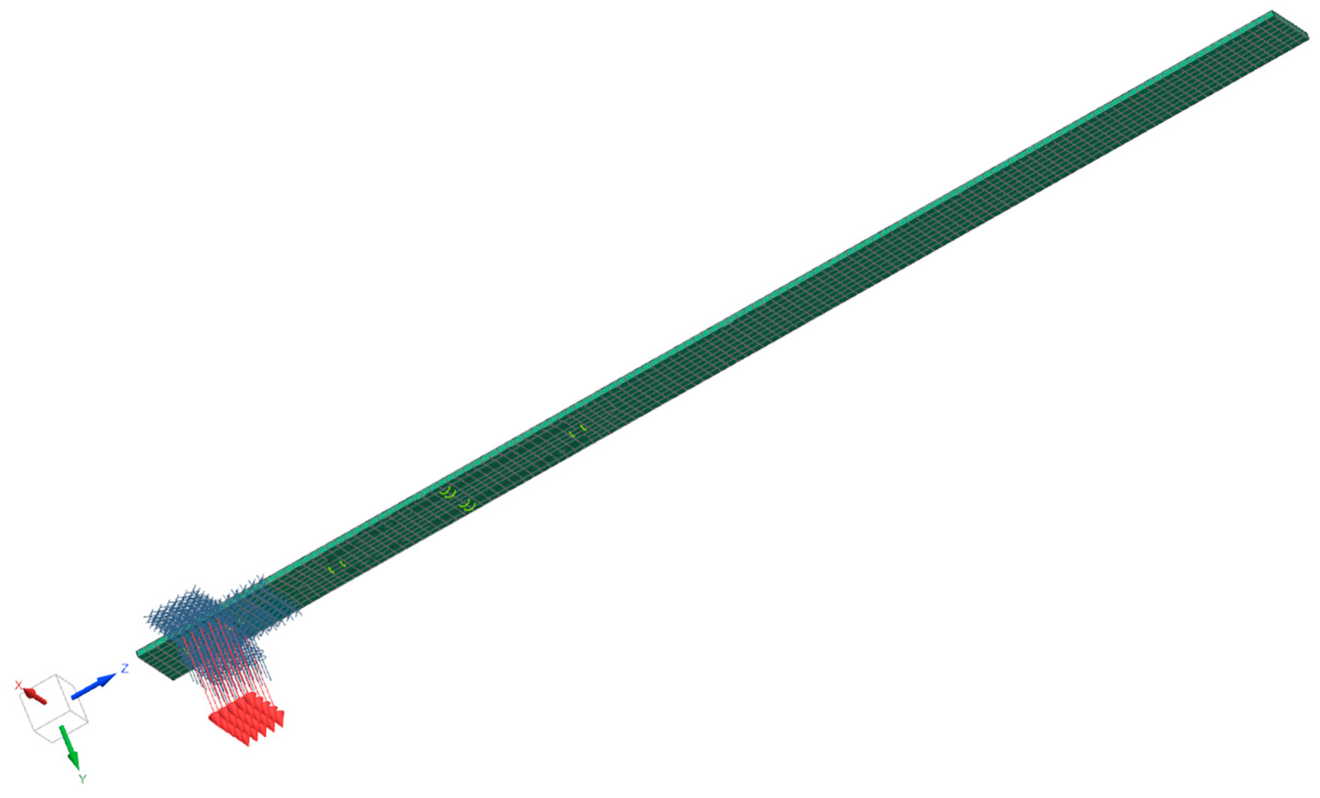
In the next step, a simulation of beam vibrations was performed. Initially, using SOL 103 Response Dynamics, the vibration modes of the beam were examined. Based on the obtained data, the considered vibration modes were limited to 1, 2, 4, and 6 modes, accounting for over 87% of the vibrating mass along the excitation axis. SOL 112 Modal Frequency Response was employed, simulating the range from 5 to 13 Hz with a 0.1 Hz step. Vibrations were imposed along the Y-axis of the simulation, while the remaining degrees of freedom were constrained using nodes defined in locations corresponding to the beam’s attachment with the vice. Subsequently, the relative strain values along the Z-axis for eight nodes located on the edges of the surface corresponding to the active area of the piezoelectric transducer were recorded. The arithmetic mean for each node was calculated and Equation (14) was applied. The simulation view with the imposed excitation and constraints is depicted in
Figure 4. All dimensions are presented in
Figure 2. The position of the transducer relative to the beam mounting is 25 mm.
6. Results
As a results of the laboratory tests plots of voltage generated by the transducer were obtained. In
Figure 5, a plot of kinematically forced free vibrations of the beams is presented. It is a result of the first test focused on studying the damping of the system. Based on those results, the damping coefficient was calculated as 0.82%.
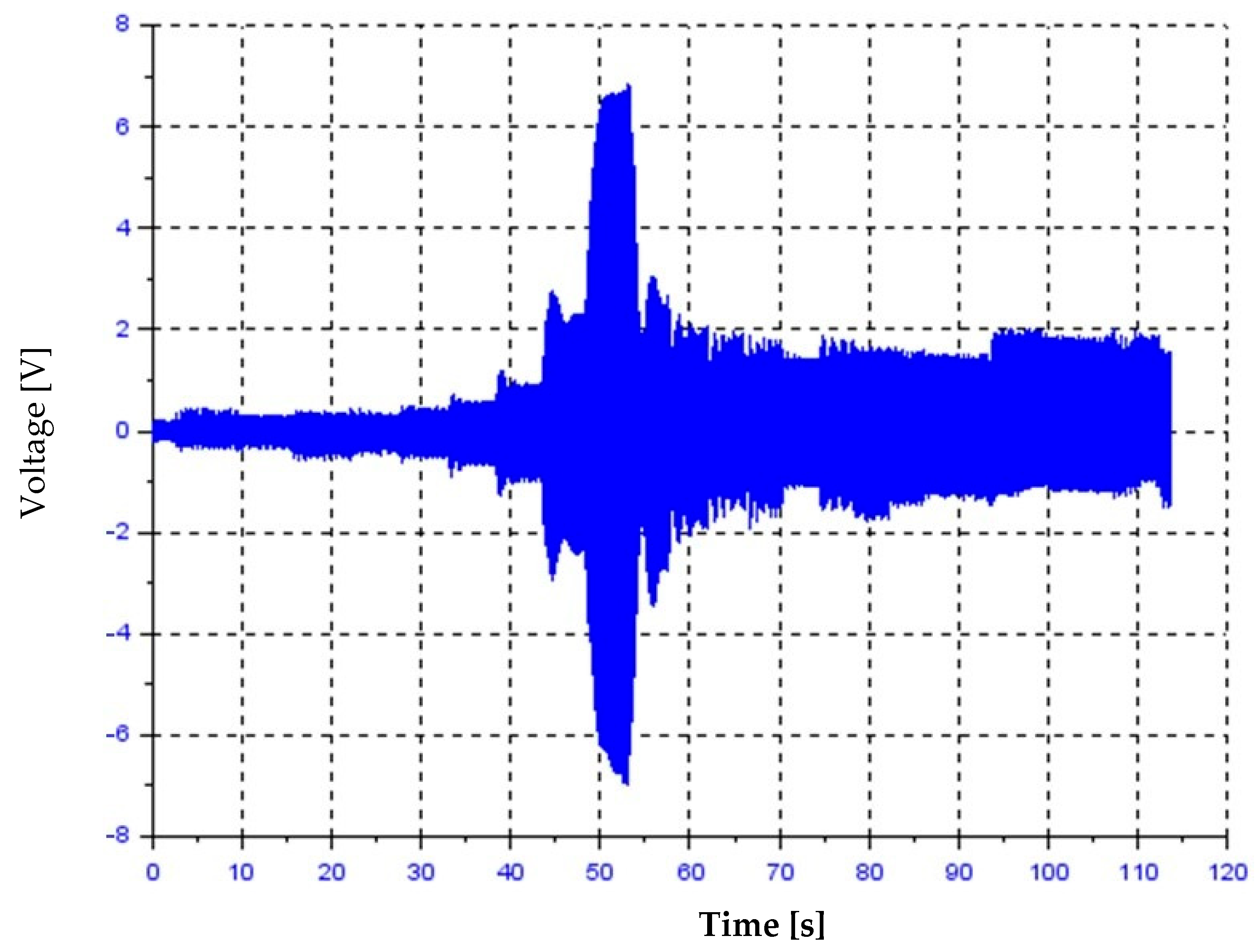
The beam’s behaviour during vibrations with increasing frequency is presented in
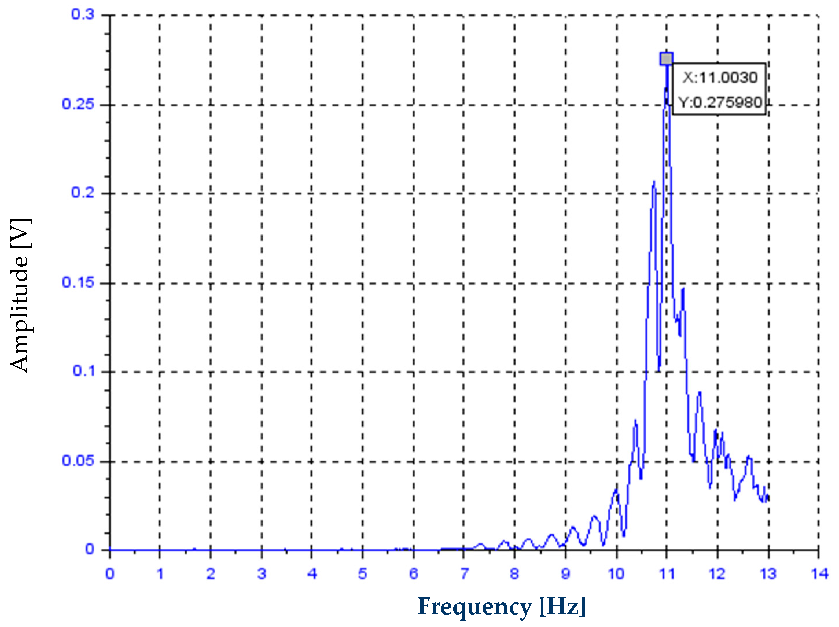
Figure 6.
Figure 7 presents results from the fast Fourier transform (FFT) analysis of this plot. The obtained resonant frequency was 11 Hz, with an average vibration amplitude at this frequency of 6.95 V. The simulation results in the frequency domain are presented in
Figure 8. The obtained resonant frequency was 11.8 Hz, with an average vibration amplitude at this frequency of 6.86 V.
The comparison of obtained results is presented in
Table 2. The experimentally obtained values were considered accurate.
The next step involved conducting vibration studies of the system in a steady state. Vibrations were applied between coordinates 50 mm and 50.5 mm along the table’s motion axis at speeds ranging from 600 mm/min to 1500 mm/min with a 50 mm/min increment. The plots were recorded when the system’s vibrations approached a sufficiently steady state, where the frequency and amplitude of vibrations were independent of time. The obtained results are presented in
Table 3.
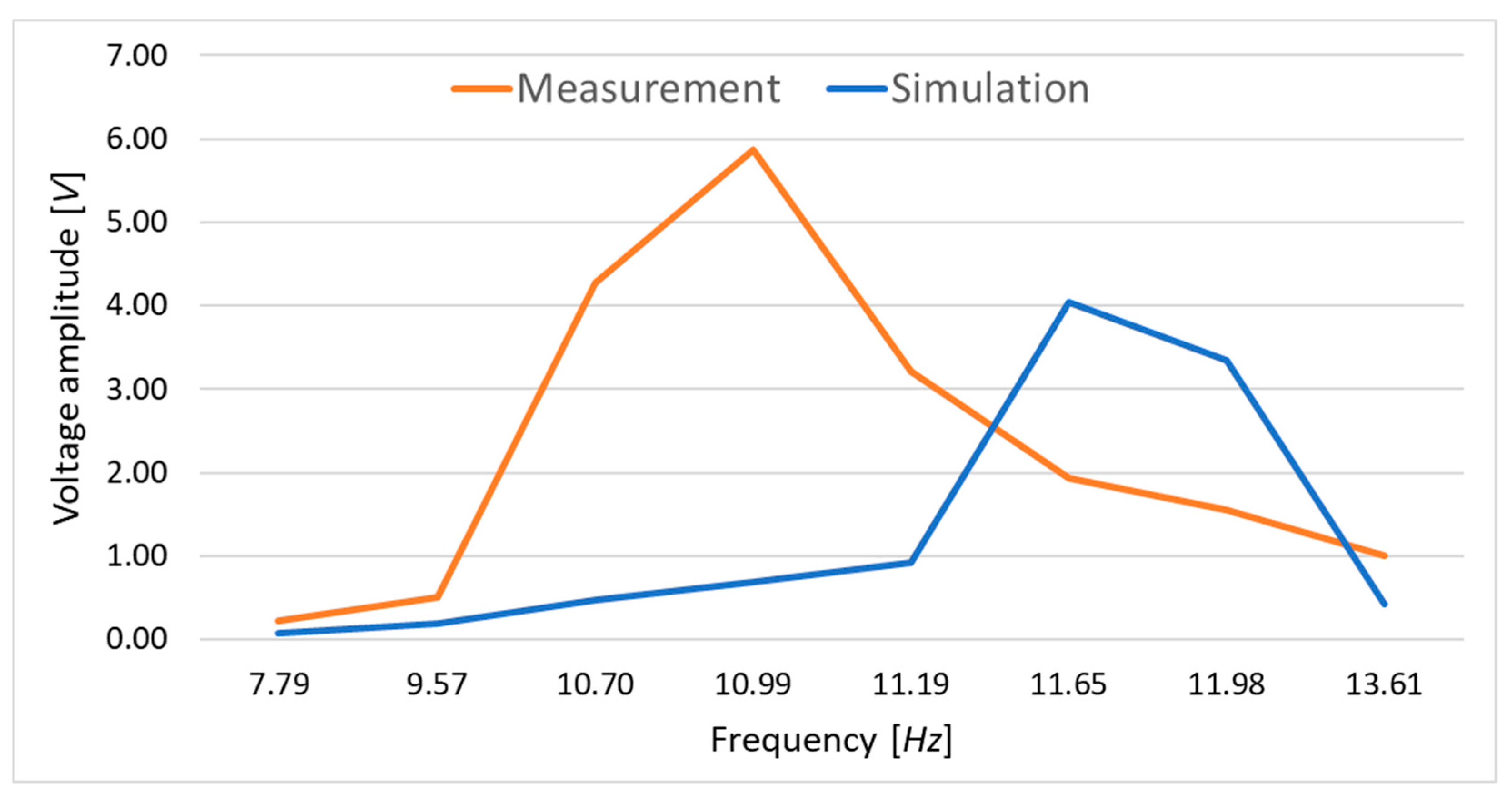
Next, a simulation of vibrations in the time domain was conducted using SOL 112 Modal Transient Response. Vibrations at selected frequencies, as shown in
Table 3, were simulated over a duration of 8 s. The simulation frequencies were chosen such that two corresponded to the range before the resonant frequencies of the experiment and simulation, five aligned with values between these frequencies, and one selected frequency matched the range beyond the resonance of the simulation and experiment. The obtained simulation results were compared with the experimental results shown in
Table 4 and represented graphically in
Figure 9. The experimentally obtained values were considered accurate.
During this research, vibrations of elements within the research setup other than the tested system were observed, such as the moving parts of the vice and table. With an increase in the excitation frequency, around the resonant frequency of the vibrating system, there was a noticeable increase in the vibration amplitudes of these elements. This somewhat negatively impacted the obtained results. Additionally, differences in the resonant frequency values of the tested system, determined during simulation and experimentation, led to discrepancies in the obtained amplitude values of the generated electrical current at a given excitation frequency. However, when comparing the peak voltage values generated by the piezoelectric element during excitation to the resonant frequency listed in
Table 2 and obtained during the study (5.87 V at 10.99 Hz for experimental research and 4.04 V at an excitation frequency of 11.65 Hz for simulation), they should be considered comparable and reliable.
The goal of this research was to demonstrate the potential application of simple computer-aided design tools for energy recovery systems from mechanical vibrations and to prove their effectiveness by comparing the results with experimental studies. The obtained minor discrepancies may be due to the influence of research infrastructure elements on the conducted laboratory tests, primarily the imperfections in the mounting of the tested beam, which affected its natural vibration frequency. However, in light of the obtained results, it can be concluded that the proposed design support tools for vibrating systems with energy recovery from mechanical vibrations are effective and enable the estimation of the operating parameters of the designed systems, including their energy efficiency under given excitation parameters.
7. Conclusions and Discussion
Based on the conducted research, it can be concluded that predicting the effectiveness of piezoelectric transducers based on simulations of the elements to which they are attached is possible with satisfactory accuracy. Simulation allows estimating the resonant frequency and vibration amplitude of the studied element. However, computer simulations might involve idealized operating conditions and a lack of consideration for the influence of vibrations and noises not directly originating from the simulated object, which can be significant beyond the resonant zone of the system under consideration. In experimental studies, it is difficult to ensure ideal mounting conditions for the tested system, leading to differences in obtained results compared to simulation outcomes for real systems. To mitigate these discrepancies, it is essential to maximize the rigidity of laboratory setup elements, the motor, and mounting components since their vibrations adversely affect the obtained results. Additionally, attention should be paid to ensuring that the resonance frequencies of the laboratory setup elements are as far removed from the measurement range as possible to minimize additional disturbances. There is also a possibility to refine the material, load, and boundary conditions in the simulation to better reflect the real experimental setup. However, these factors are challenging to directly simulate without precise information on material properties and boundary conditions that may vary in real-world experiments. Simulation parameters can be adjusted based on the material properties, loads, and boundary conditions observed in the experimental setup. By doing so, discrepancies can be reduced and bring the simulation results closer to the actual experimental outcomes.
The assumption of homogeneity in the MFC (macro-fiber composite) used in the proposed mathematical framework simplifies the analysis, but it is important to note that this assumption may not fully represent real-world conditions. Potential stress concentrations due to fibre distribution and the interactions at the interfaces, particularly between the epoxy and PZT layers, can significantly affect the mechanical and electrical performance of the energy harvesting system. These factors could lead to localized variations in material properties, which may impact the overall efficiency of the system. While these effects have not been incorporated into the current model, they are recognized as important considerations for further research. Future studies will aim to refine the model by incorporating these inhomogeneities, allowing for a more accurate representation of the system’s behaviour under real-world operating conditions.
The current study primarily focuses on the operational range of 7–15 Hz for the MFC piezoelectric transducers, based on the specific characteristics of the system and the intended application, which involves vibrations induced by moving vehicles in a wheeled motion. While this frequency range provides valuable insights into the system’s performance, it is recognized that these results may have limited applicability to a wider range of operational conditions, including higher or lower frequencies and varying load conditions. The proposed mathematical framework, while effective within this specific range, can be extended to other frequencies and load conditions through further research and experimental validation. Future work will aim to explore these broader operating conditions to improve the general applicability and versatility of the model in different engineering applications.
Developed mathematical models integrated with computer-aided design tools and utilizing the finite element method to determine the dynamic characteristics of the studied system enable effective support in its design and manufacturing, aimed at maximizing energy efficiency under assumed operational parameters, especially in terms of excitation frequency. The validation conducted on the proposed model indicates its effectiveness in this regard. Its application may contribute to the design and production of systems with higher performance, including those with variable geometries. The utilization of such tools accelerates design processes without the need for prototyping and testing mechanical vibration energy recovery systems. This results in reduced production costs and enables the manufacturing of systems tailored to specific anticipated working conditions while ensuring high efficiency.


