
Toward More Efficient Large-Scale Green Hydrogen Systems via Waste Heat Recovery and ORC


Abstract
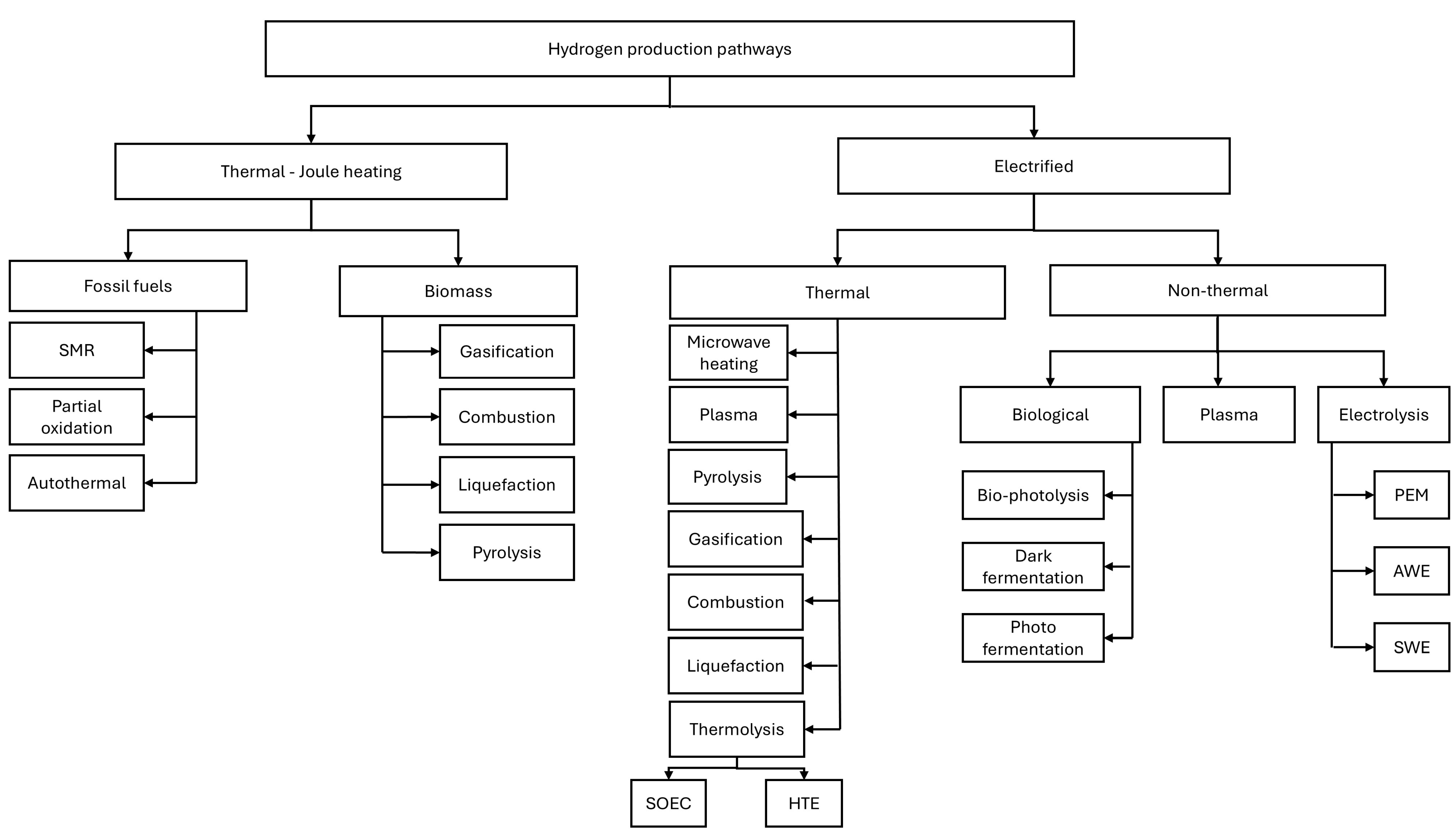
1. Introduction
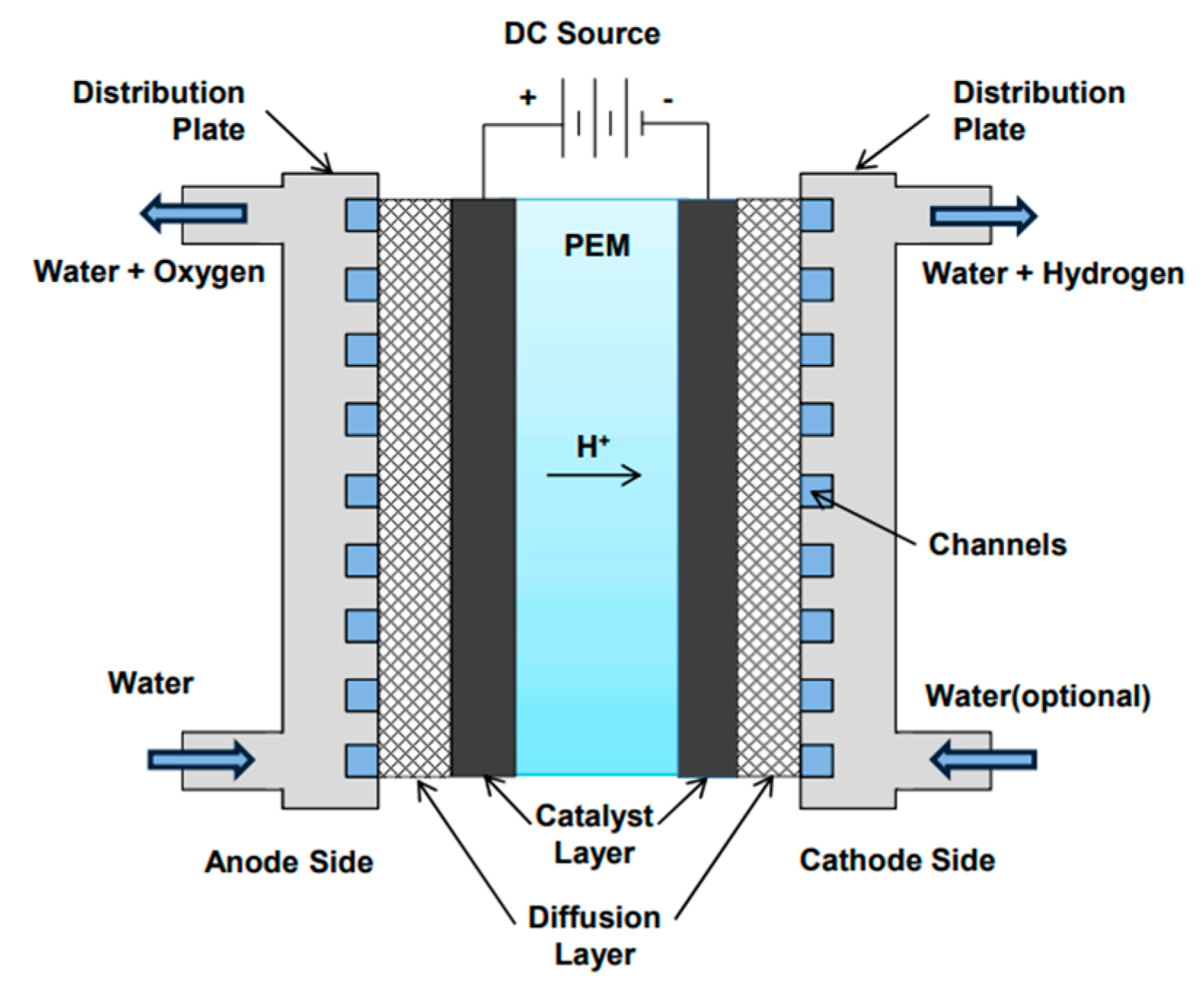
1.1. Water Electrolyzer
1.2. Proton Exchange Membrane Electrolyzer
- (a)
- Water splits at the anode:
- (b)
- Protons migrate through the PEM toward the cathode.
- (c)
- The protons (H+) recombine with electrons supplied from the external circuit to form molecular hydrogen gas:
1.3. Organic Refrigerant Cycle
1.4. Aim and Novelty
2. Methods
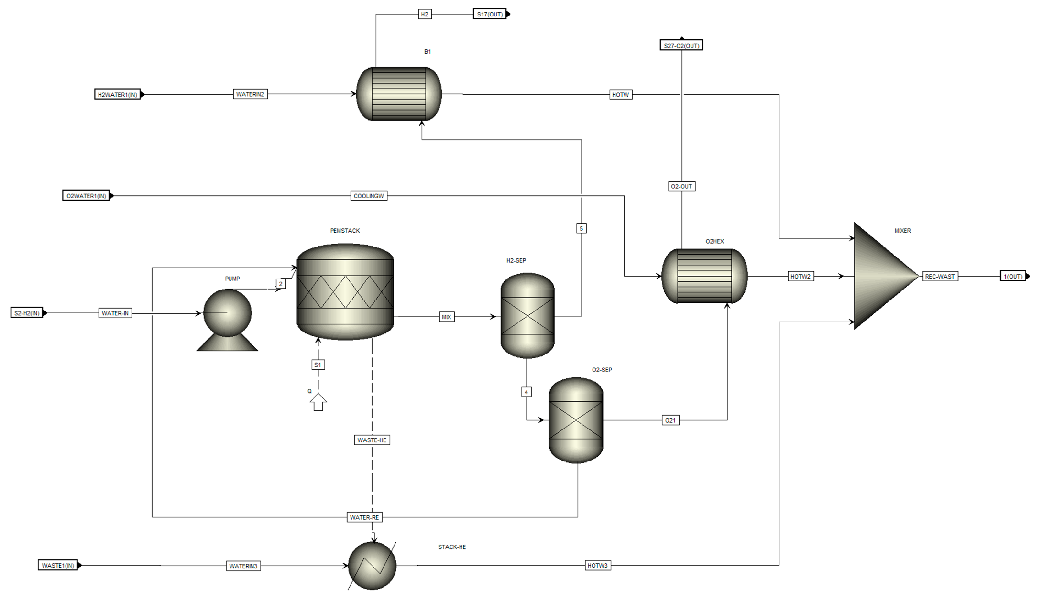
2.1. Technical Analysis
2.2. Model Development
2.3. Maximizing ORC Efficiency
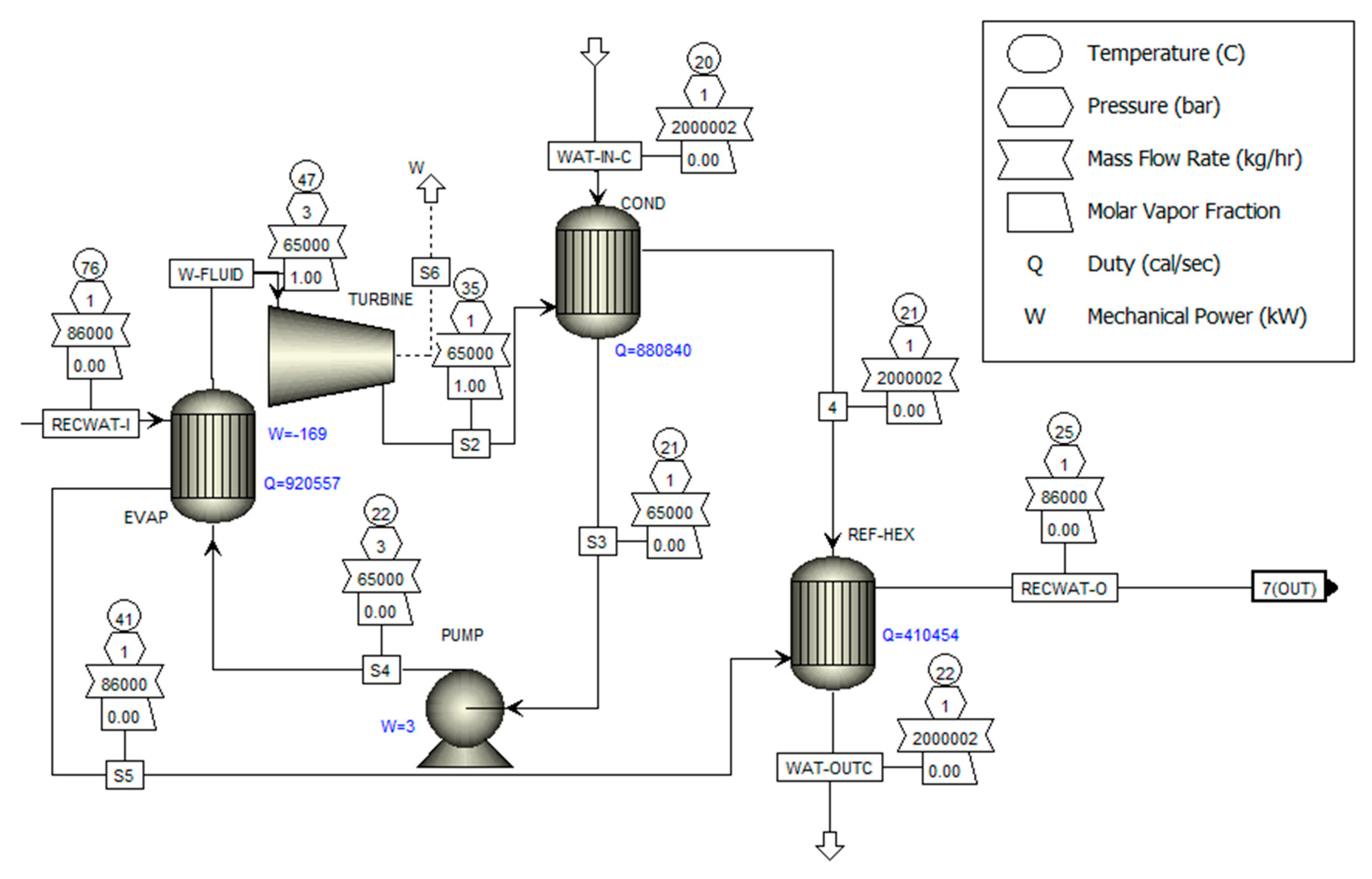
3. Results
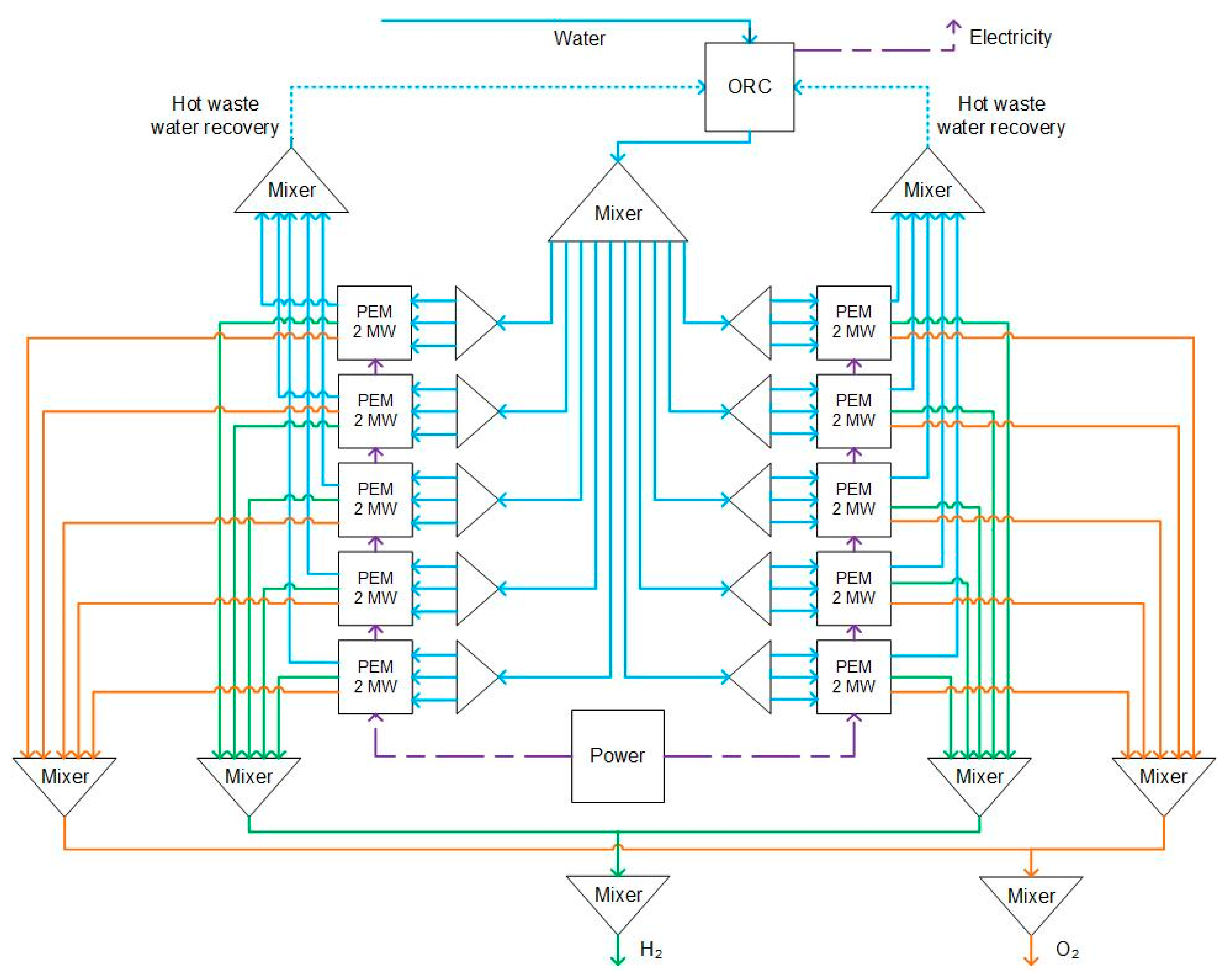
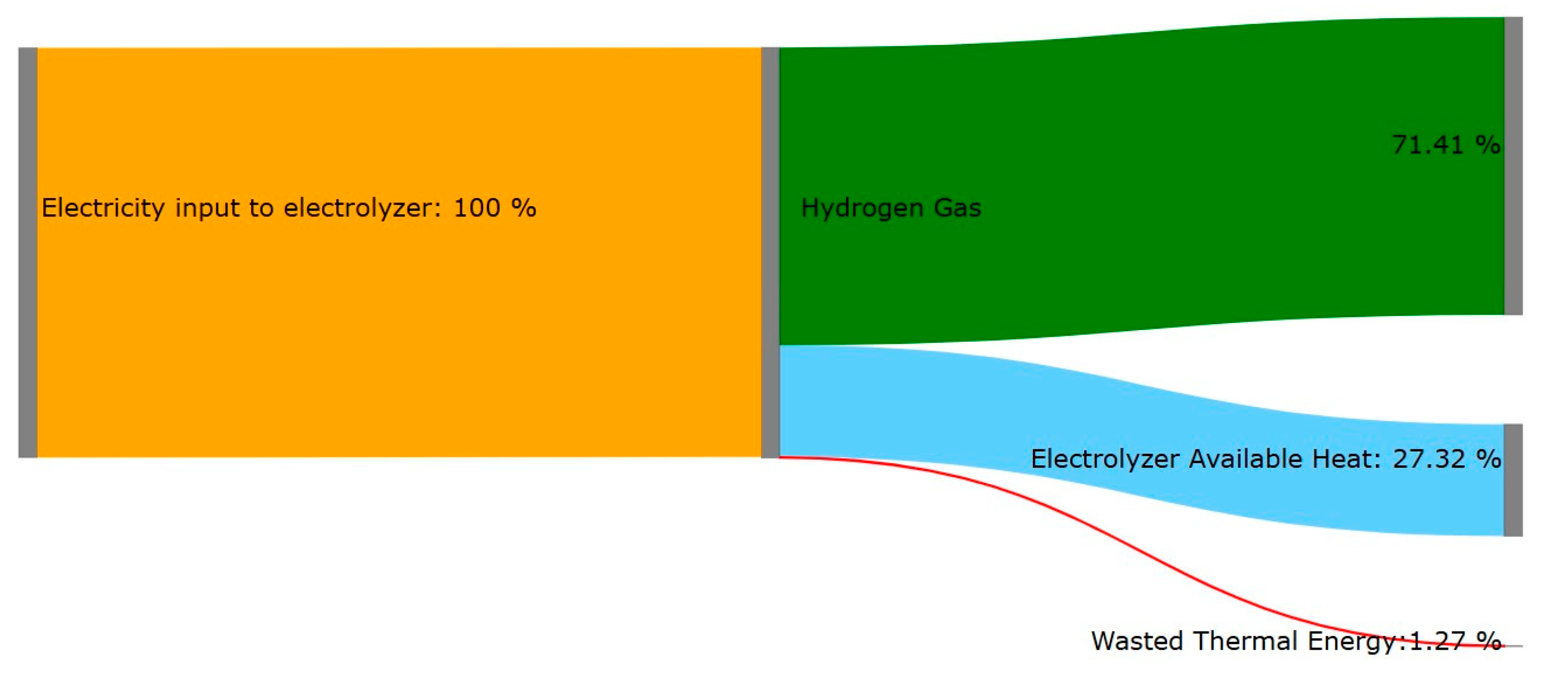
3.1. Hydrogen Production and Heat Recovery at a 20 MW PEM Electrolyzer Plant
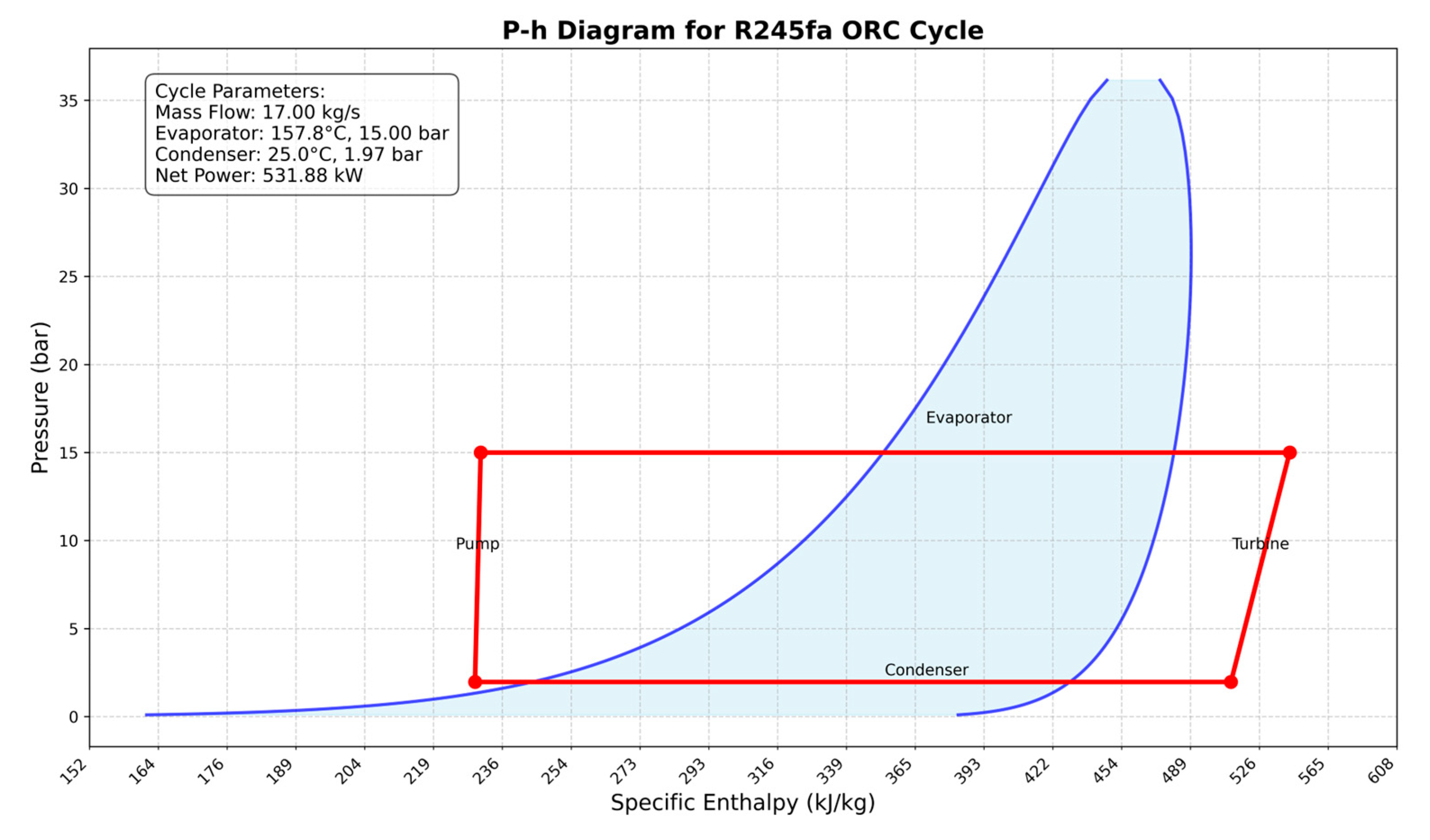
3.2. Organic Refrigerant Cycle
3.3. Maximizing ORC Efficiency
4. Discussion
Author Contributions
Funding
Institutional Review Board Statement
Informed Consent Statement
Data Availability Statement
Acknowledgments
Conflicts of Interest
Abbreviations and Symbols
| AEM | Anion exchange membrane |
| HTE | High-temperature electrolysis |
| ORC | Organic refrigerant cycle |
| PEMI | Proton exchange membrane |
| SCOECs | Solid Oxide Electrolyzer Cells |
| SWE | Supercritical water electrolysis |
| HHV | Higher heating value |
| MW | Megawatt |
| kW | Kilowatt |
| kg/hr | Kilograms per hour |
| °C | Degrees Celsius |
| bar | Pressure unit |
| η | Efficiency |
| H2 | Hydrogen |
| O2 | Oxygen |
| e− | Electron |
| H+ | Proton |
| R245fa | Organic refrigerant used in ORC |
| h | Enthalpy |
| Q | Heat transfer |
| W | Work output |
| T | Temperature |
| P | Pressure |
Appendix A

| Statistic | |
| Number of variables | 6270 |
| Number of incident variables | 6263 |
| Number of fixed variables | 563 |
| Number of free variables | 5707 |
| Number of equations | 5707 |
| Number of excluded equations | 0 |
| Number of non-zeros | 20,563 |
| Number of incidents non-zeros | 19,457 |
| Number of incomplete connections | 0 |
References
- Nyangon, J.; Darekar, A. Advancements in hydrogen energy systems: A review of levelized costs, financial incentives and technological innovations. Innov. Green Dev. 2024, 3, 100149. [Google Scholar] [CrossRef]
- Wolfram, P.; Kyle, P.; Fuhrman, J.; O’Rourke, P.; McJeon, H. The hydrogen economy can reduce costs of climate change mitigation by up to 22%. One Earth 2024, 7, 885–895. [Google Scholar] [CrossRef]
- Niknezhad, S.S.; Staack, D.; Pistikopoulos, E.N. Hydrogen Production Plant Via an Intensified Plasma-Based Technology. Available online: https://ssrn.com/abstract=4889037 (accessed on 1 May 2025).
- Mizeraczyk, J.; Jasiński, M. Plasma processing methods for hydrogen production. Eur. Phys. J. Appl. Phys. 2016, 75, 24702. [Google Scholar] [CrossRef]
- Yang, H.; Nuran Zaini, I.; Pan, R.; Jin, Y.; Wang, Y.; Li, L.; Caballero, J.J.B.; Shi, Z.; Subasi, Y.; Nurdiawati, A.; et al. Distributed electrified heating for efficient hydrogen production. Nat. Commun. 2024, 15, 3868. [Google Scholar] [CrossRef]
- Wappler, M.; Unguder, D.; Lu, X.; Ohlmeyer, H.; Teschke, H.; Lueke, W. Building the green hydrogen market–Current state and outlook on green hydrogen demand and electrolyzer manufacturing. Int. J. Hydrogen Energy 2022, 47, 33551–33570. [Google Scholar] [CrossRef]
- Wang, Y.; Diaz, D.F.R.; Chen, K.S.; Wang, Z.; Adroher, X.C. Materials, technological status, and fundamentals of PEM fuel cells–a review. Mater. Today 2020, 32, 178–203. [Google Scholar] [CrossRef]
- Iglesias Garcia, S.; Ferreiro Garcia, R.; Carbia Carril, J.; Iglesias Garcia, D. A review of thermodynamic cycles used in low temperature recovery systems over the last two years. Renew. Sustain. Energy Rev. 2018, 81, 760–767. [Google Scholar] [CrossRef]
- Lümmen, N.; Karouach, A.; Tveitan, S. Thermo-economic study of waste heat recovery from condensing steam for hydrogen production by PEM electrolysis. Energy Convers. Manag. 2019, 185, 21–34. [Google Scholar] [CrossRef]
- Van der Roest, E.; Bol, R.; Fens, T.; van Wijk, A. Utilisation of waste heat from PEM electrolysers—Unlocking local optimisation. Int. J. Hydrogen Energy 2023, 48, 27872–27891. [Google Scholar] [CrossRef]
- Yang, B.; Zhang, R.; Shao, Z.; Zhang, C. The economic analysis for hydrogen production cost towards electrolyzer technologies: Current and future competitiveness. Int. J. Hydrogen Energy 2023, 48, 13767–13779. [Google Scholar] [CrossRef]
- Jensen, S.H. Solid Oxide Electrolyser Cell. Ph.D. Thesis, Technical University of Denmark, Kongens Lyngby, Denmark, 2007. [Google Scholar]
- Sood, S.; Prakash, O.; Boukerdja, M.; Dieulot, J.Y.; Ould-Bouamama, B.; Bressel, M.; Gehin, A.L. Generic Dynamical Model of PEM Electrolyser under Intermittent Sources. Energies 2020, 13, 6556. [Google Scholar] [CrossRef]
- Tchanche, B.F.; Lambrinos, G.; Frangoudakis, A.; Papadakis, G. Low-grade heat conversion into power using organic Rankine cycles–A review of various applications. Renew. Sustain. Energy Rev. 2011, 15, 3963–3979. [Google Scholar] [CrossRef]
- Sheshpoli, M.A.; Ajarostaghi, S.S.M.; Delavar, M.A. Thermodynamic analysis of waste heat recovery from hybrid system of proton exchange membrane fuel cell and vapor compression refrigeration cycle by recuperative organic Rankine cycle. J. Therm. Anal. Calorim. 2019, 135, 1699–1712. [Google Scholar] [CrossRef]
- Wilberforce, T.; Olabi, A.G.; Muhammad, I.; Alaswad, A.; Sayed, E.T.; Abo-Khalil, A.G.; Maghrabie, H.M.; Elsaid, K.; Abdelkareem, M.A. Recovery of waste heat from proton exchange membrane fuel cells—A review. Int. J. Hydrogen Energy 2024, 52, 933–972. [Google Scholar] [CrossRef]
- Nguyen, H.Q.; Shabani, B. Proton exchange membrane fuel cells heat recovery opportunities for combined heating/cooling and power applications. Energy Convers. Manag. 2020, 204, 112328. [Google Scholar] [CrossRef]
- He, T.; Shi, R.; Peng, J.; Zhuge, W.; Zhang, Y. Waste heat recovery of a PEMFC system by using organic rankine cycle. Energies 2016, 9, 267. [Google Scholar] [CrossRef]
- Younas, M.; Shafique, S.; Hafeez, A.; Javed, F.; Rehman, F. An Overview of Hydrogen Production: Current Status, Potential, and Challenges. Fuel 2022, 316, 123317. [Google Scholar] [CrossRef]
- Wang, L.; Husar, A.; Zhou, T.; Liu, H. A parametric study of PEM fuel cell performances. Int. J. Hydrogen Energy 2003, 28, 1263–1272. [Google Scholar] [CrossRef]
- Nur Ozdemir, S.; Taymaz, I.; Okumuş, E.; Gül Boyacı San, F.; Akgün, F. Experimental investigation on performance evaluation of PEM electrolysis cell by using a Taguchi method. Fuel 2023, 344, 128021. [Google Scholar] [CrossRef]
- Yang, J.; Ye, Z.; Yu, B.; Ouyang, H.; Chen, J. Simultaneous experimental comparison of low-GWP refrigerants as drop-in replacements to R245fa for Organic Rankine cycle application: R1234ze(Z), R1233zd(E), and R1336mzz(E). Energy 2019, 173, 721–731. [Google Scholar] [CrossRef]
- Kajurek, J.; Rusowicz, A.; Grzebielec, A.; Bujalski, W.; Futyma, K.; Rudowicz, Z. Selection of refrigerants for a modified organic Rankine cycle. Energy 2019, 168, 1–8. [Google Scholar] [CrossRef]
- María Villarreal Vives, A.; Wang, R.; Roy, S.; Smallbone, A. Techno-economic analysis of large-scale green hydrogen production and storage. Appl. Energy 2023, 346, 121333. [Google Scholar] [CrossRef]
| Technology | Electrolyte Type | Operating Temperature | Efficiency | Advantages | Challenges |
|---|---|---|---|---|---|
| Alkaline electrolyzer (AWE) | Liquid alkaline solution (KOH) | 60–90 °C | 70–80% | Mature technology, lower capital costs, uses non-precious metal catalysts | Larger physical footprint, slower response to load changes, lower current density |
| Proton exchange membrane (PEM) electrolyzer | Solid polymer membrane | 50–80 °C | 60–70% | Compact design, rapid response to power fluctuations, higher current density | Higher capital costs due to the use of precious metal catalysts, sensitive to water impurities |
| Solid oxide electrolyzer cells (SOECs) | Solid ceramic material | 700–1000 °C | Up to 100% (theoretical) | High efficiency due to elevated temperatures, potential for waste heat utilization | High operating temperatures lead to material degradation, currently in developmental stages |
| Anion exchange membrane (AEM) electrolyzer | Anion-exchange membrane | <100 °C | Emerging technology | Potential for lower costs using non-precious metal catalysts combines benefits of AWE and PEM | Still under research, durability and performance need further validation |
| Supercritical water electrolysis (SWE) | Supercritical water | >374 °C and >22.1 MPa | High | High reaction rates, direct production of high-pressure hydrogen | Requires materials that can withstand extreme conditions, currently experimental |
| High-pressure electrolysis | Varies | Similar to AWE or PEM | Similar to base technology | Produces compressed hydrogen directly, reducing the need for external compression | Requires robust system design to ensure safety and durability under high pressure |
| High-temperature electrolysis (HTE) | Steam (solid oxide cells) | 500–850 °C | Higher than AWE and PEM | Improved efficiency by utilizing thermal energy, suitable for integration with heat sources | High operating temperatures necessitate durable materials, system complexity |
| Unit | Parameter | Value |
|---|---|---|
| PEM stack | Water flow | 324 kg/hr |
| Water temperature | 25 °C | |
| Water pressure | 1 bar | |
| Average energy | 18.015 MW | |
| Waste heat recovery | Water flow | 7482 kg/hr |
| Water temperature | 25 °C | |
| Water pressure | 1 bar | |
| H2 cooling system | Water flow | 688 kg/hr |
| Water temperature | 25 °C | |
| Water pressure | 1 bar | |
| O2 cooling system | Water flow | 430 kg/hr |
| Water temperature | 25 °C | |
| Water pressure | 1 bar |
| Unit | Parameter | Value |
|---|---|---|
| Evaporator | Water inflow | 86,000 kg/hr |
| Turbine | Discharge pressure | 1.3 bar |
| Efficiency | 70% | |
| Pump | Discharge pressure | 2.7 bar |
| Pump | 70% | |
| Condenser | Water inflow | 2 × 10⁶ kg/hr |
| Water temperature | 20 °C | |
| Pressure | 1 bar | |
| R245fa coolant | Flow rate | 65,000 kg/hr |
| Pressure | 1.3 bar |
| Parameter | Value |
|---|---|
| Working fluid | 86,000 kg/hr |
| Water in temperature | 25 °C |
| Water-in pressure | 1 bar |
| Total flow-in water | 324 kg/hr |
| Power input | 20,000 kW |
| Water-in through pumps | 8 kW |
| Streams | Water Inflow to PEM Stack | H2 Stream | O2 Stream |
|---|---|---|---|
| Temperature (°C) | 25 | 30.47 | 32.03 |
| Pressure (bar) | 1 | 29.97 | 29.98 |
| Mass density (kg/m3) | 993.96 | 2.36 | 38.69 |
| Average energy MW | 18.02 | 2.02 | 31.99 |
| Mass flows (kg/hr) | 324 | 36.25 | 287.75 |
| Enthalpy flow (W) | −1.43 × 10⁶ | 879.98 | −147.58 |
| Stream | Water-In * | HOTW * | HOTW2 * | HOTW3 * | Rec-Wast * |
|---|---|---|---|---|---|
| Temperature (°C) | 25 | 33.32 | 31.84 | 82.97 | 76.47 |
| Pressure (bar) | 1 | 0.98 | 0.99 | 1 | 0.98 |
| Mass density (kg/m3) | 939.96 | 985.88 | 987.32 | 963.11 | 942.80 |
| Average energy (MW) | 18.02 | 18.02 | 18.02 | 18.02 | 18.02 |
| Mass flow (kg/hr) | 8600 | 688 | 430 | 7482 | 8600 |
| Enthalpy flow (W) | −3.81 × 10⁷ | −3.04 | −1.9 × 10⁶ | −3.26 × 10⁷ | −3.75 × 10⁷ |
| Energy-for Units | Value (kW) |
|---|---|
| Total required electricity for H2 production | 14,536.44 |
| Potential recovered waste heat from stacks | 5463.65 |
| Heat loss for cooling O2 | 37.01 |
| Heat loss for cooling H2 | 72.01 |
| Stream | Stream 2 * | Rec Water * | R245fd-IN * | R245fa-OUT * |
|---|---|---|---|---|
| Temperature (°C) | 76.47 | 24.8 | 21.44 | 30.97 |
| Pressure (bar) | 0.98 | 0.88 | 1.3 | 1.3 |
| Mass density (kg/m3) | 942.80 | 994.12 | 1350.42 | 7.17 |
| Average energy MW | 18.02 | 18.02 | 134.04 | 134.04 |
| Mass flows (kg/hr) | 86,000 | 86,000 | 65,000 | 65,000 |
| Enthalpy flow (W) | −3.75 × 10⁸ | −3.81 × 10⁸ | −1.62 × 10⁸ | −1.58 × 10⁸ |
| Variable | Values |
|---|---|
| Electricity from ORC | 169.97 kW |
| Exit water temperature from condenser | 22 °C |
| Total waste heat recovered | 27.32% |
| Required electricity | 2.7 kW |
| Exit water for plant cooling | 25 °C |
| Variable | Before | After |
|---|---|---|
| Working fluid R245fa mass flow rate kg/hr | 65,000 | 61,200 |
| Cooling water flow rate kg/hr | 2,000,002 | 1,033,092 |
| Power output kW | 169.97 | 555.88 |
| Net power kW | 165.96 | 532.41 |
Disclaimer/Publisher’s Note: The statements, opinions and data contained in all publications are solely those of the individual author(s) and contributor(s) and not of MDPI and/or the editor(s). MDPI and/or the editor(s) disclaim responsibility for any injury to people or property resulting from any ideas, methods, instructions or products referred to in the content. |
© 2025 by the authors. Licensee MDPI, Basel, Switzerland. This article is an open access article distributed under the terms and conditions of the Creative Commons Attribution (CC BY) license (https://creativecommons.org/licenses/by/4.0/).
Share and Cite
Niknezhad, S.S.; Moghaddamali, F.; Pistikopoulos, E. Toward More Efficient Large-Scale Green Hydrogen Systems via Waste Heat Recovery and ORC. Appl. Sci. 2025, 15, 5224. https://doi.org/10.3390/app15105224
Niknezhad SS, Moghaddamali F, Pistikopoulos E. Toward More Efficient Large-Scale Green Hydrogen Systems via Waste Heat Recovery and ORC. Applied Sciences. 2025; 15(10):5224. https://doi.org/10.3390/app15105224
Chicago/Turabian StyleNiknezhad, Shayan S., Forough Moghaddamali, and Efstratios Pistikopoulos. 2025. "Toward More Efficient Large-Scale Green Hydrogen Systems via Waste Heat Recovery and ORC" Applied Sciences 15, no. 10: 5224. https://doi.org/10.3390/app15105224
APA StyleNiknezhad, S. S., Moghaddamali, F., & Pistikopoulos, E. (2025). Toward More Efficient Large-Scale Green Hydrogen Systems via Waste Heat Recovery and ORC. Applied Sciences, 15(10), 5224. https://doi.org/10.3390/app15105224