

Fuzzy Logic-Based Energy Management System for Regenerative Braking of Electric Vehicles with Hybrid Energy Storage System


Abstract
1. Introduction
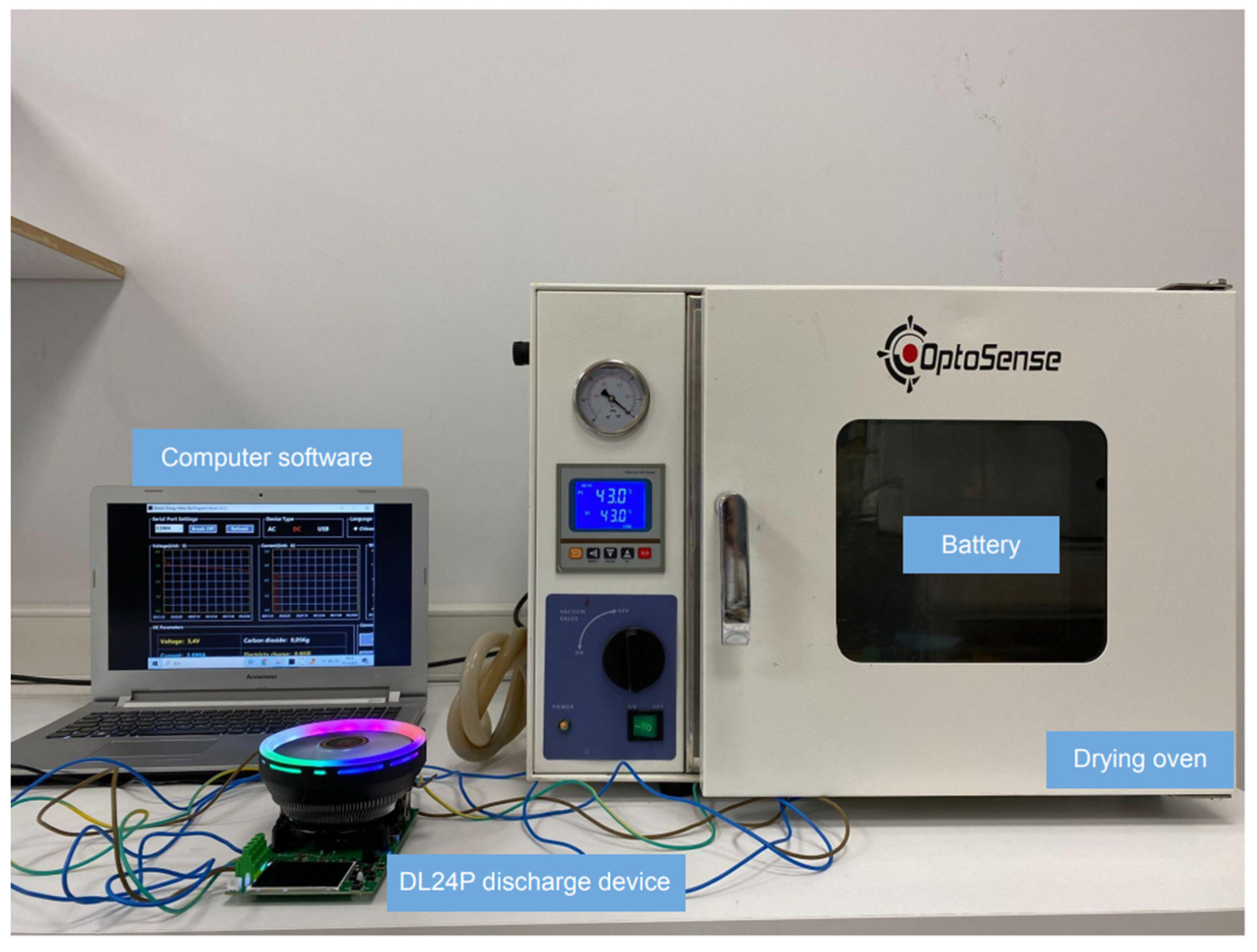
2. Experimental Preparation for Fuzzy Logic Application
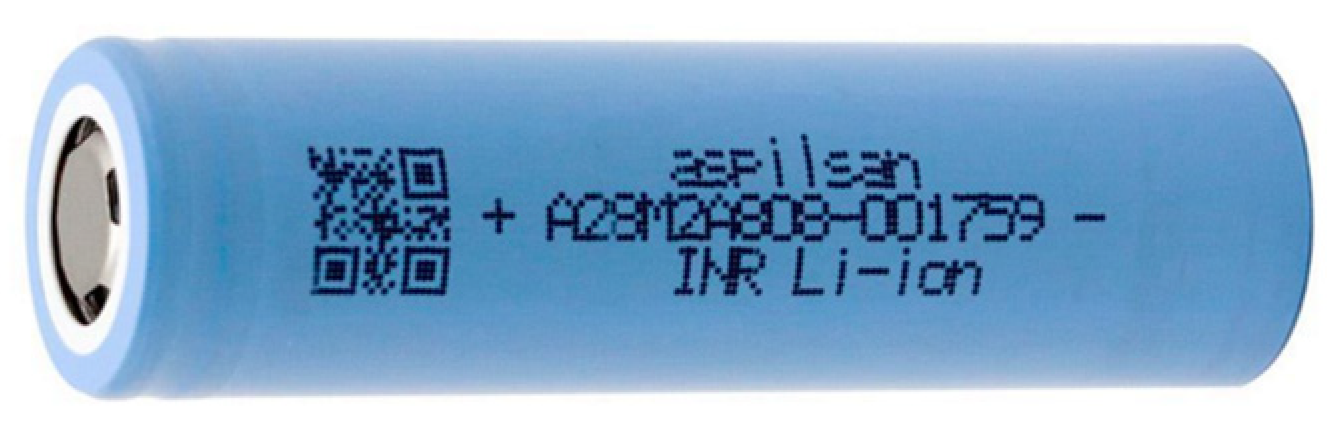
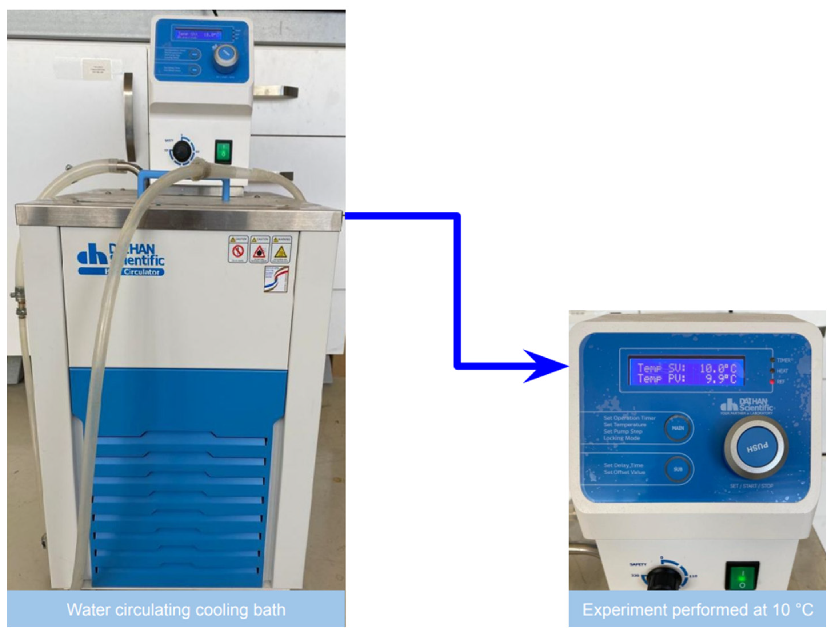
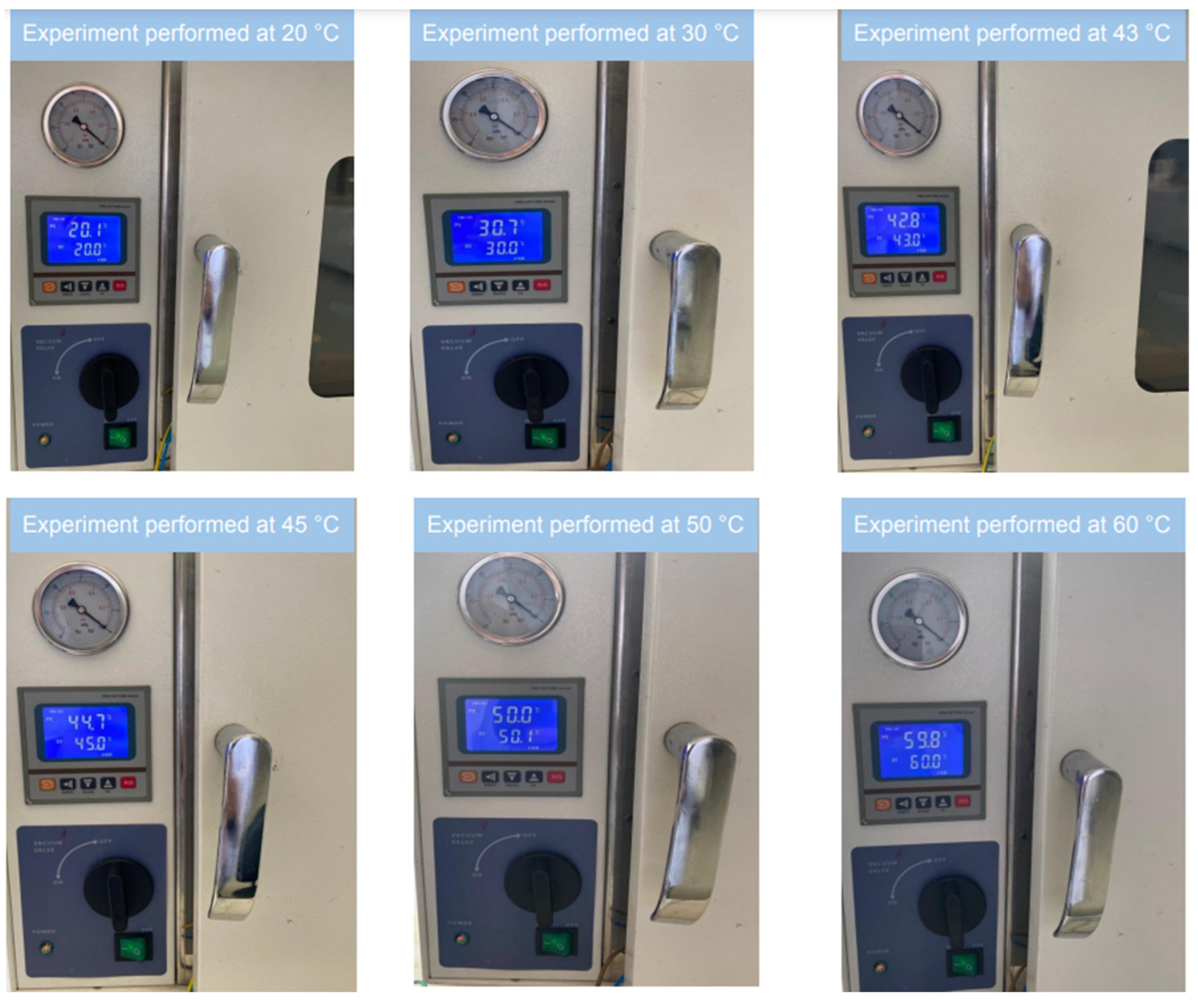
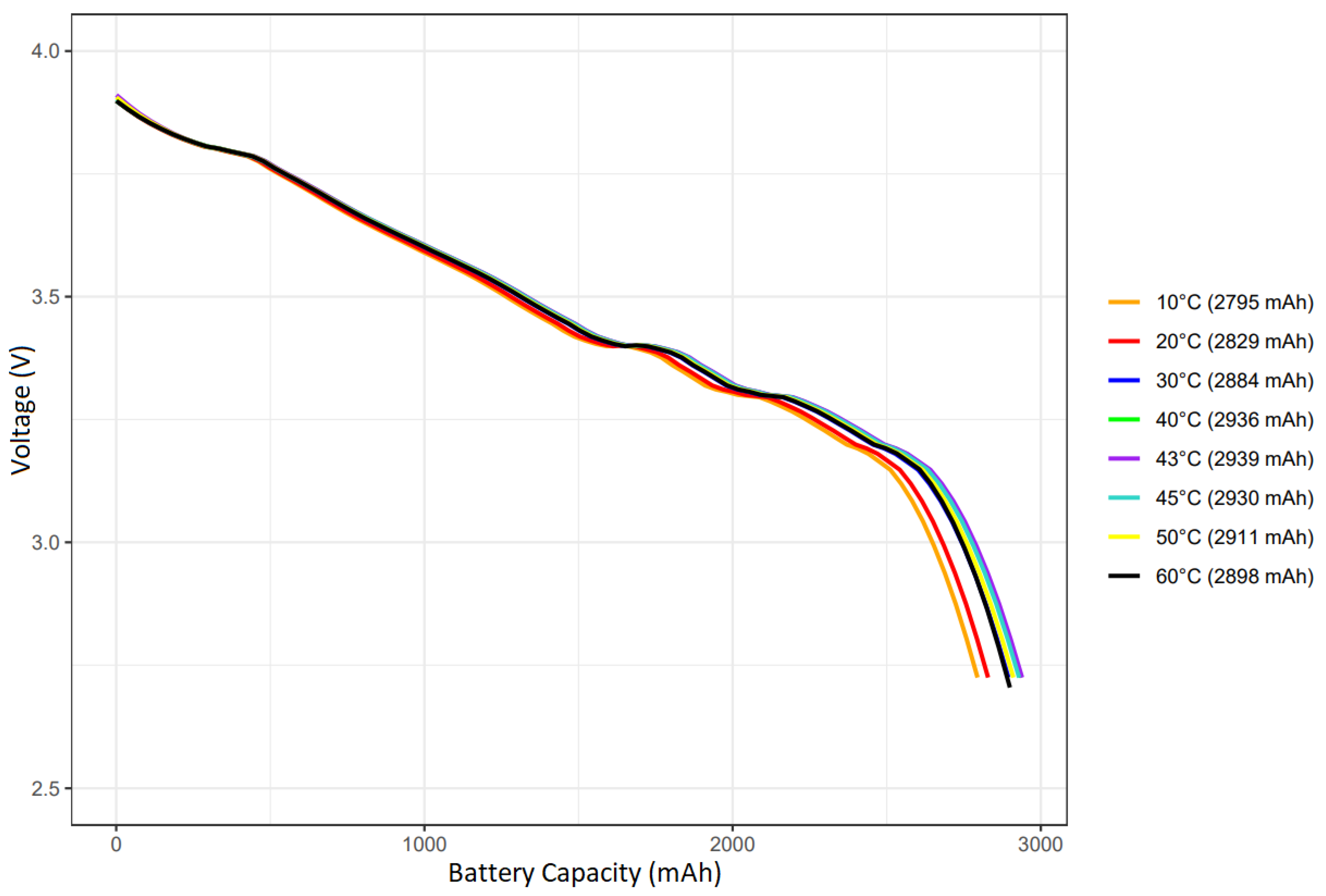
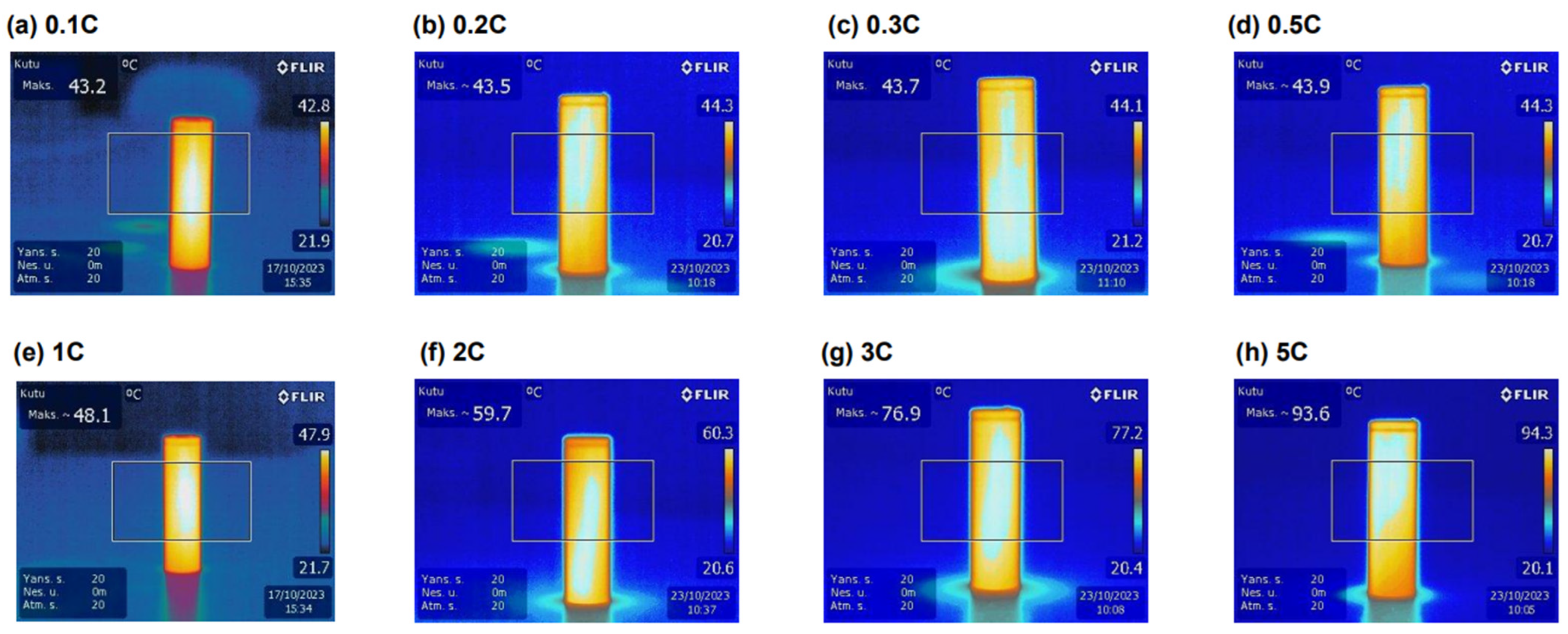
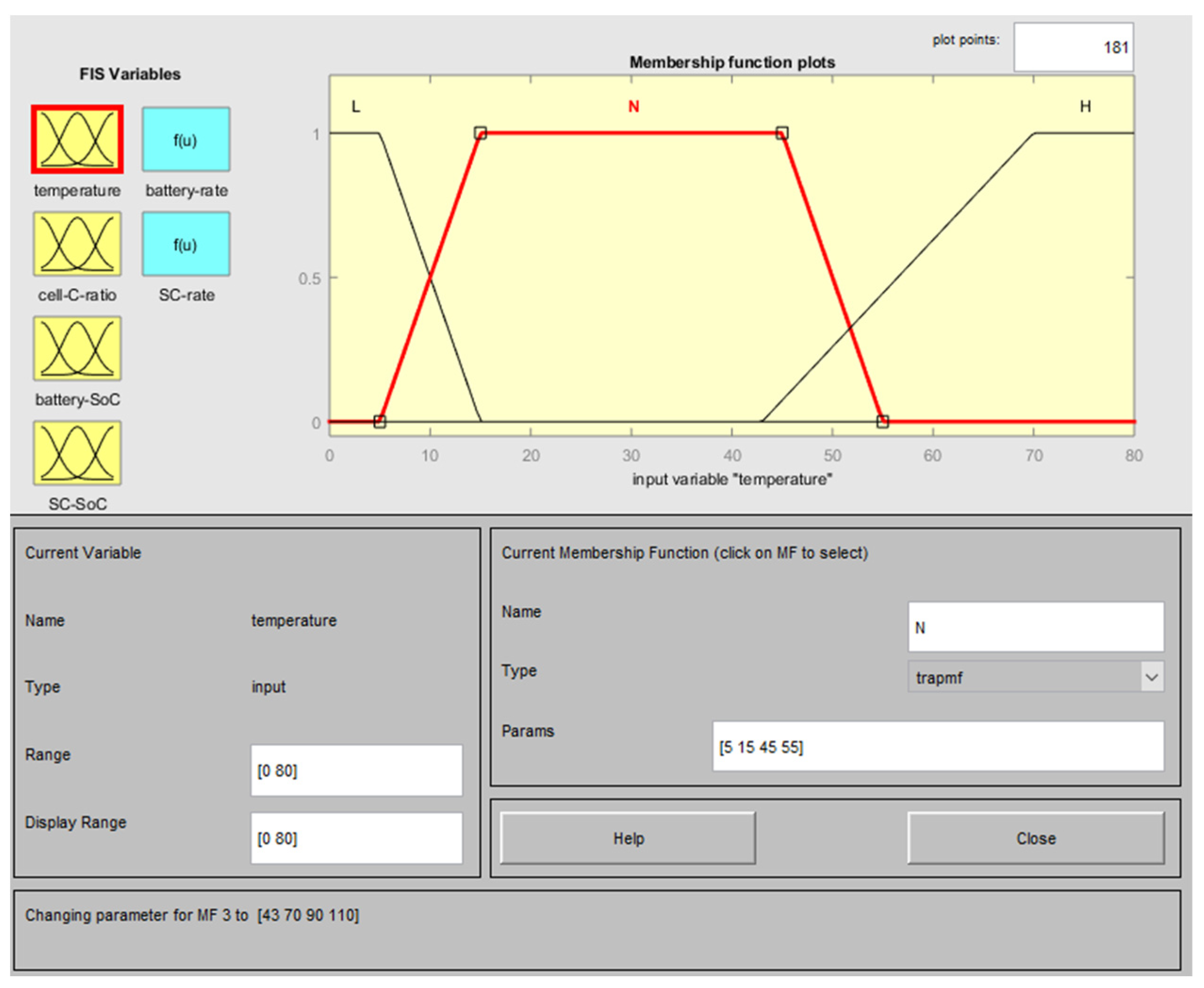
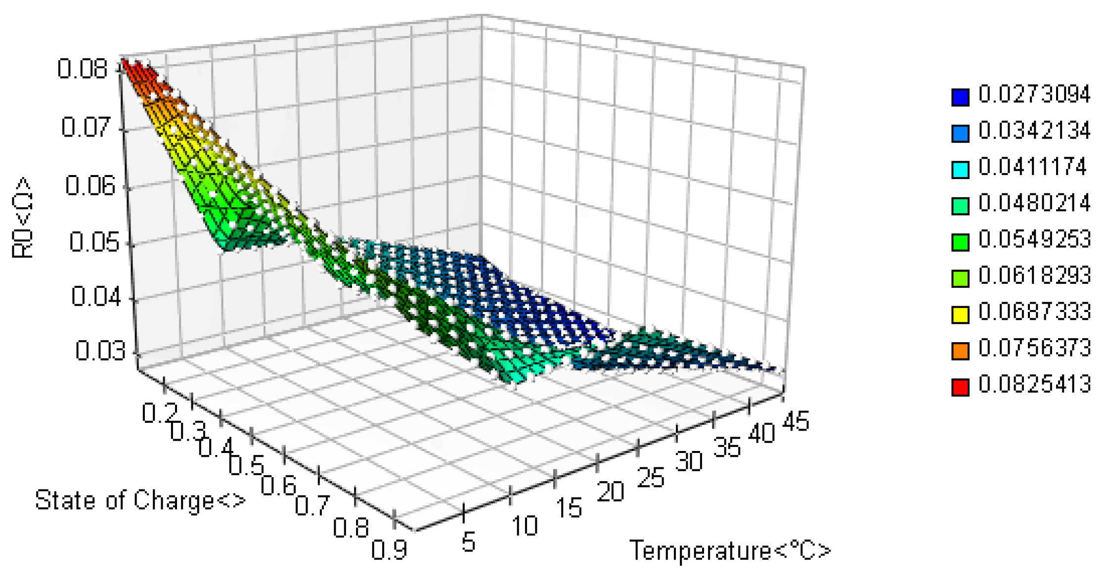
2.1. Temperature
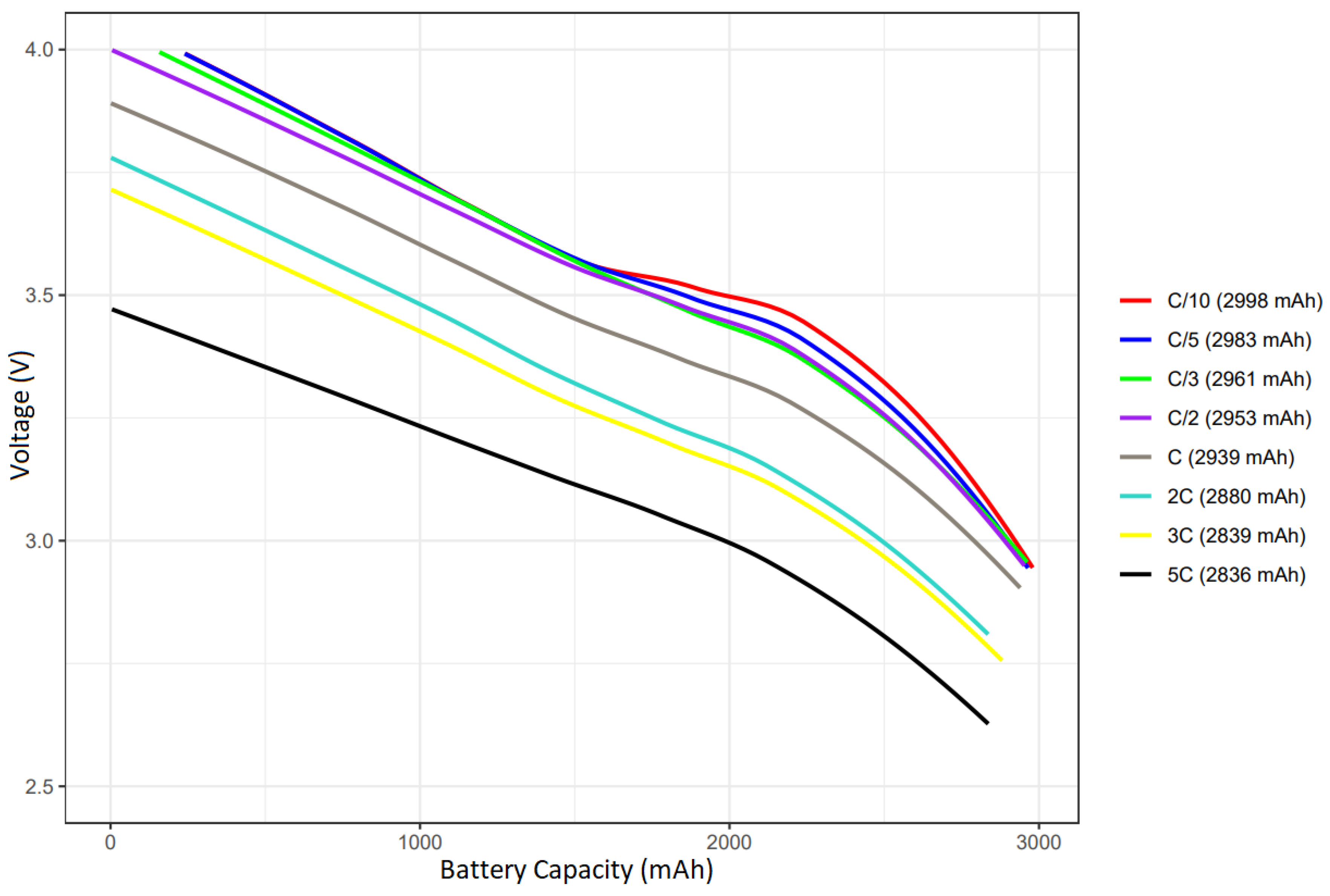
2.2. Battery Charging Current
2.3. Battery and Supercapacitor State-of-Charge
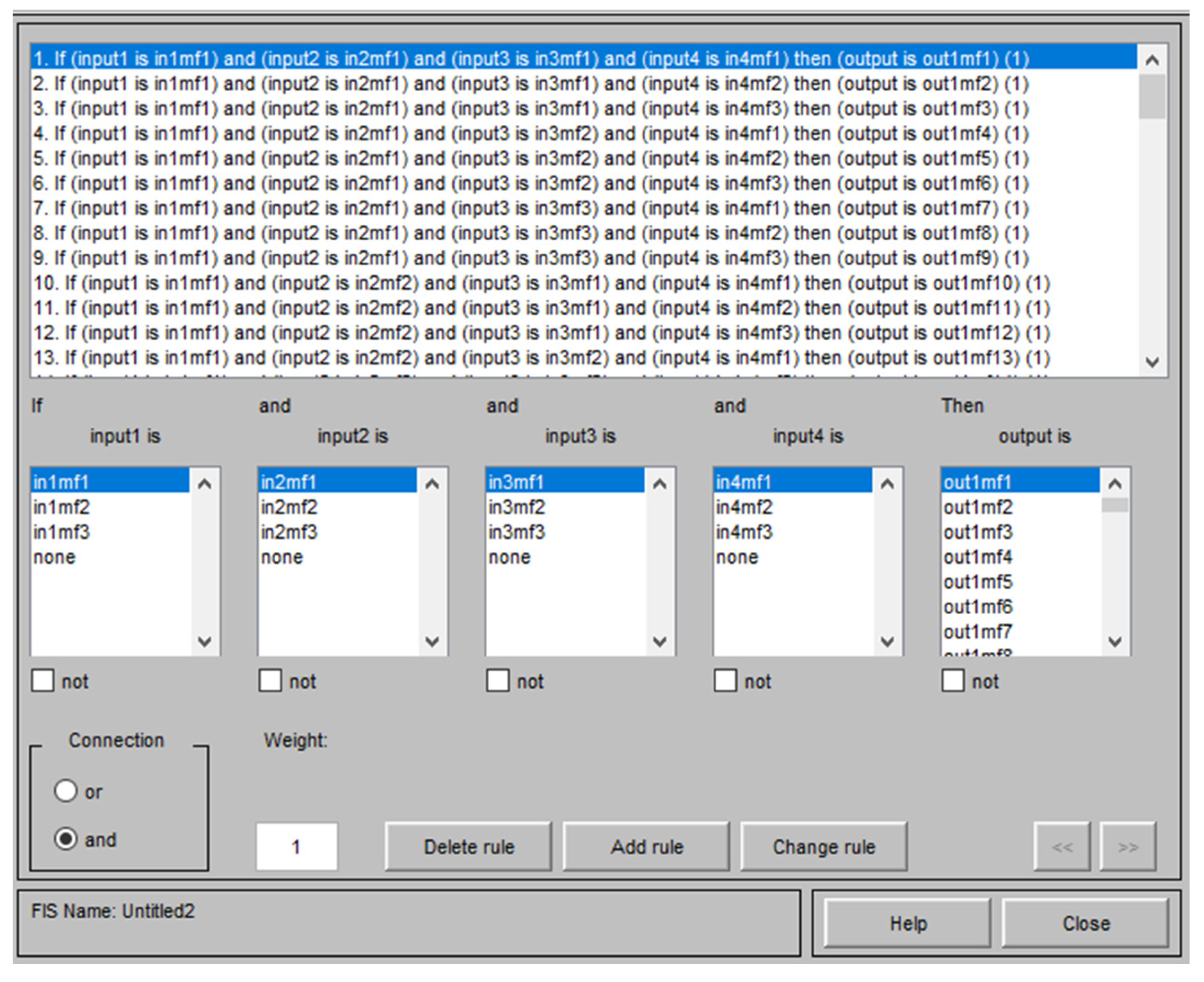
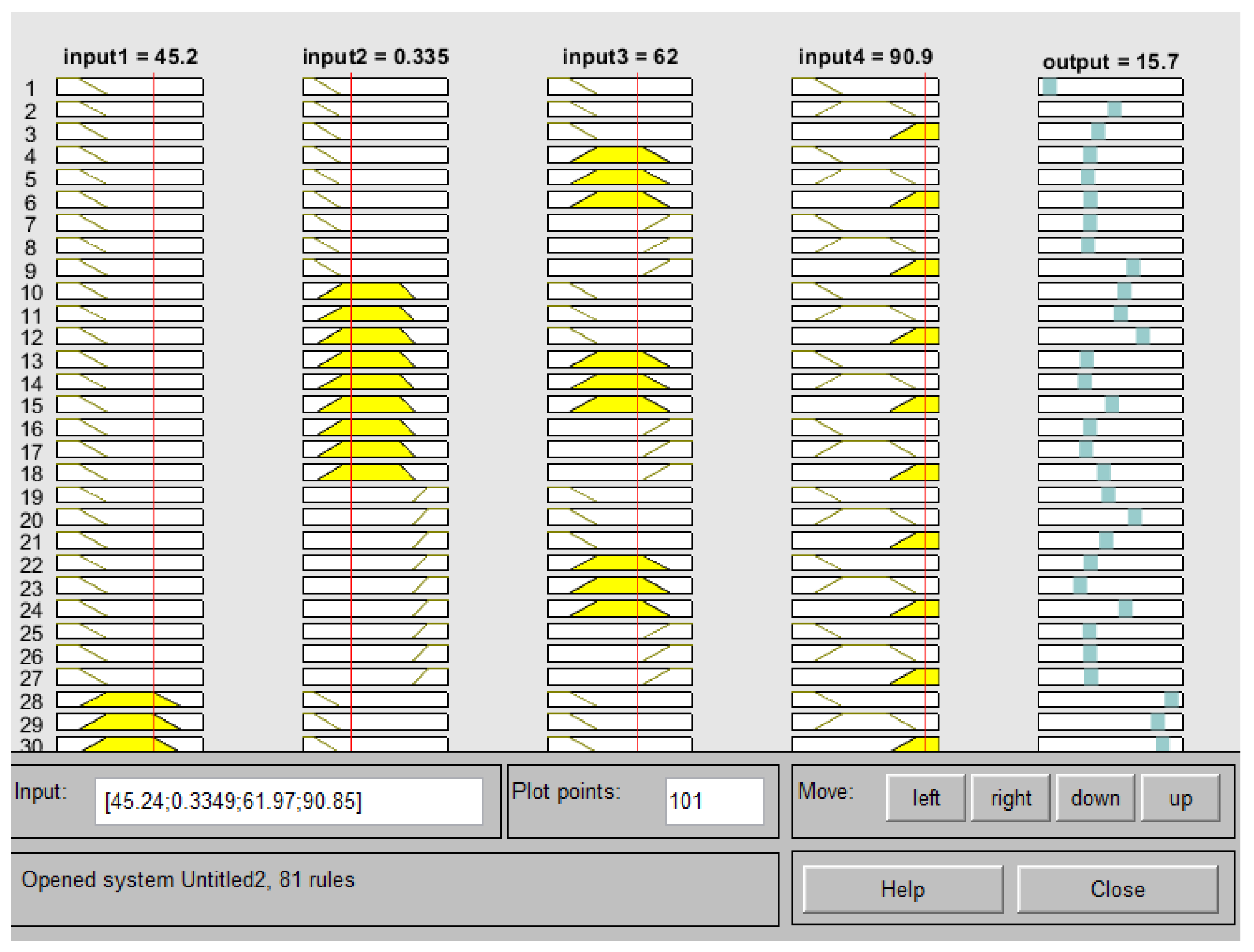
3. Design of Fuzzy Logic System
3.1. Data Preparation
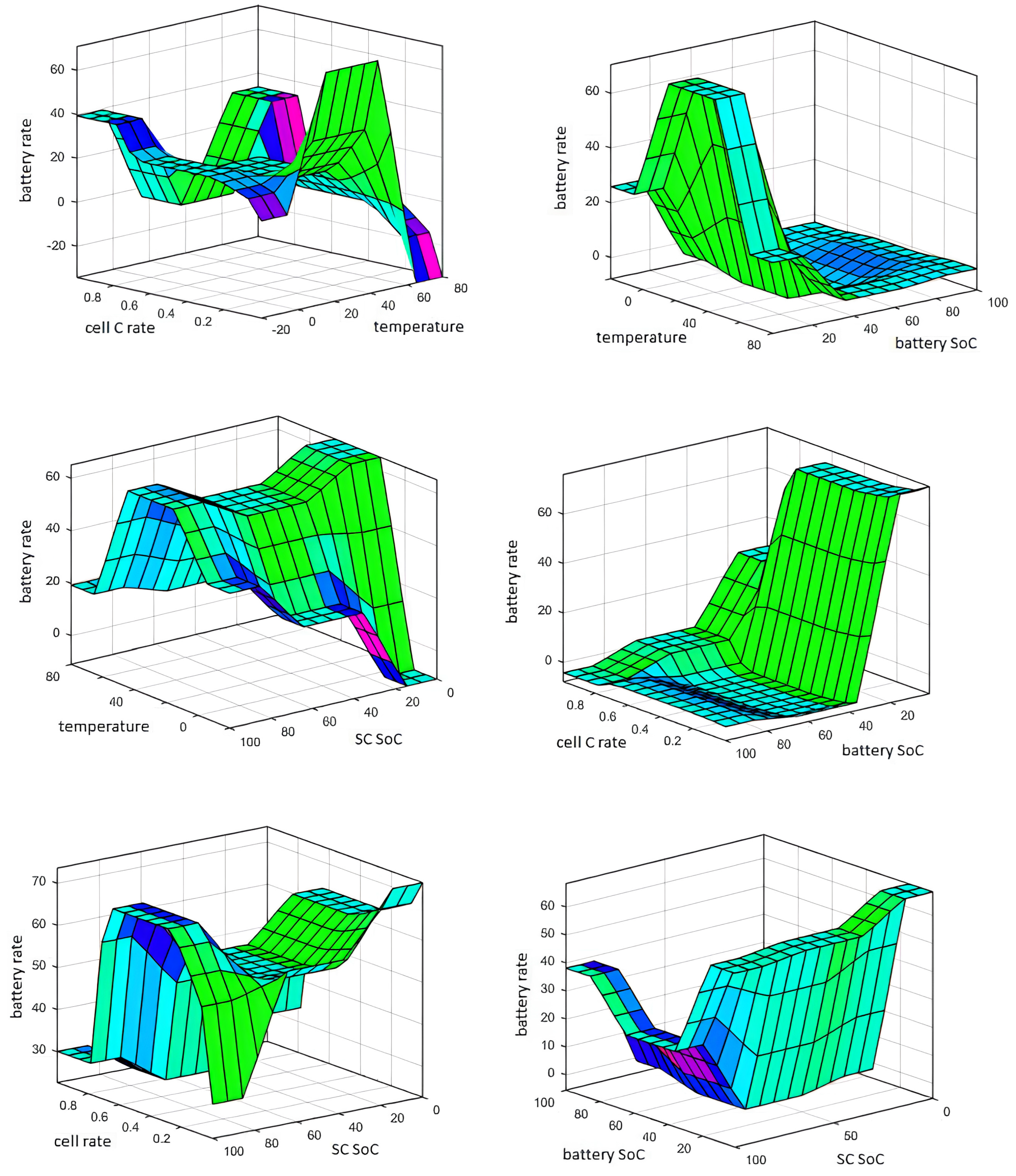
3.2. Building the Model
4. Simulation and Analysis
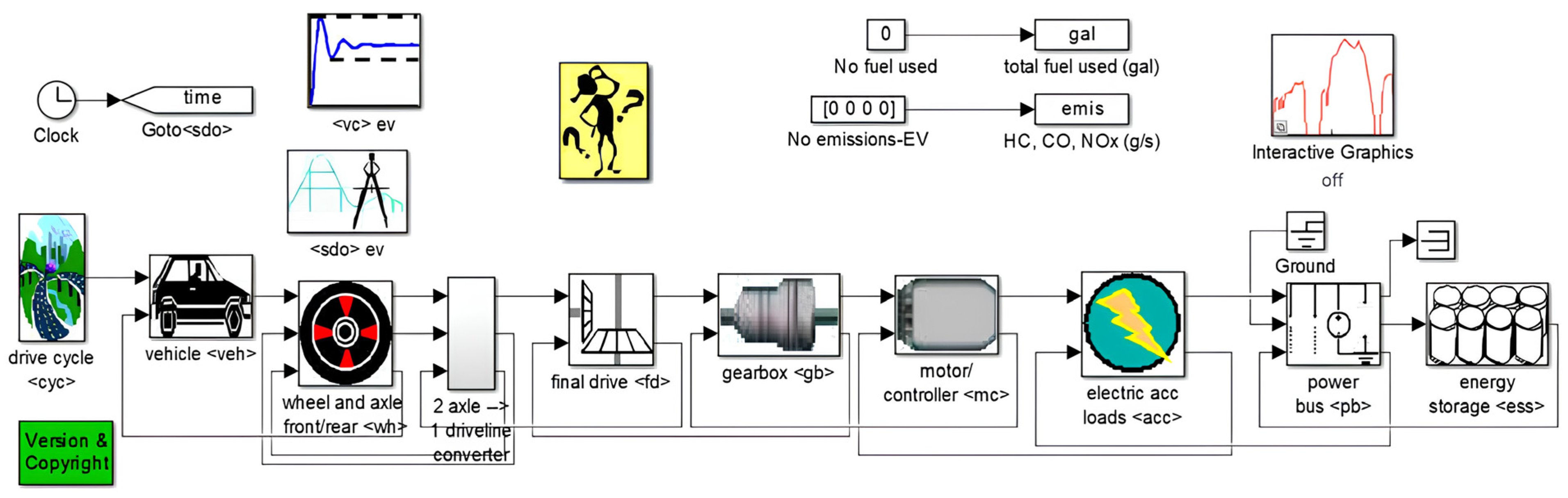
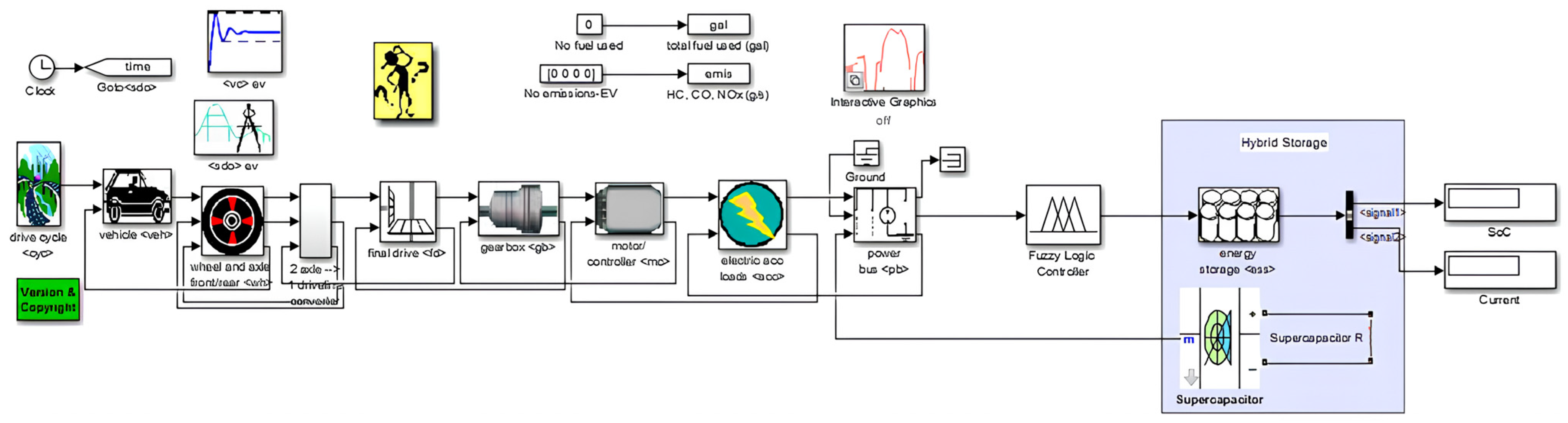
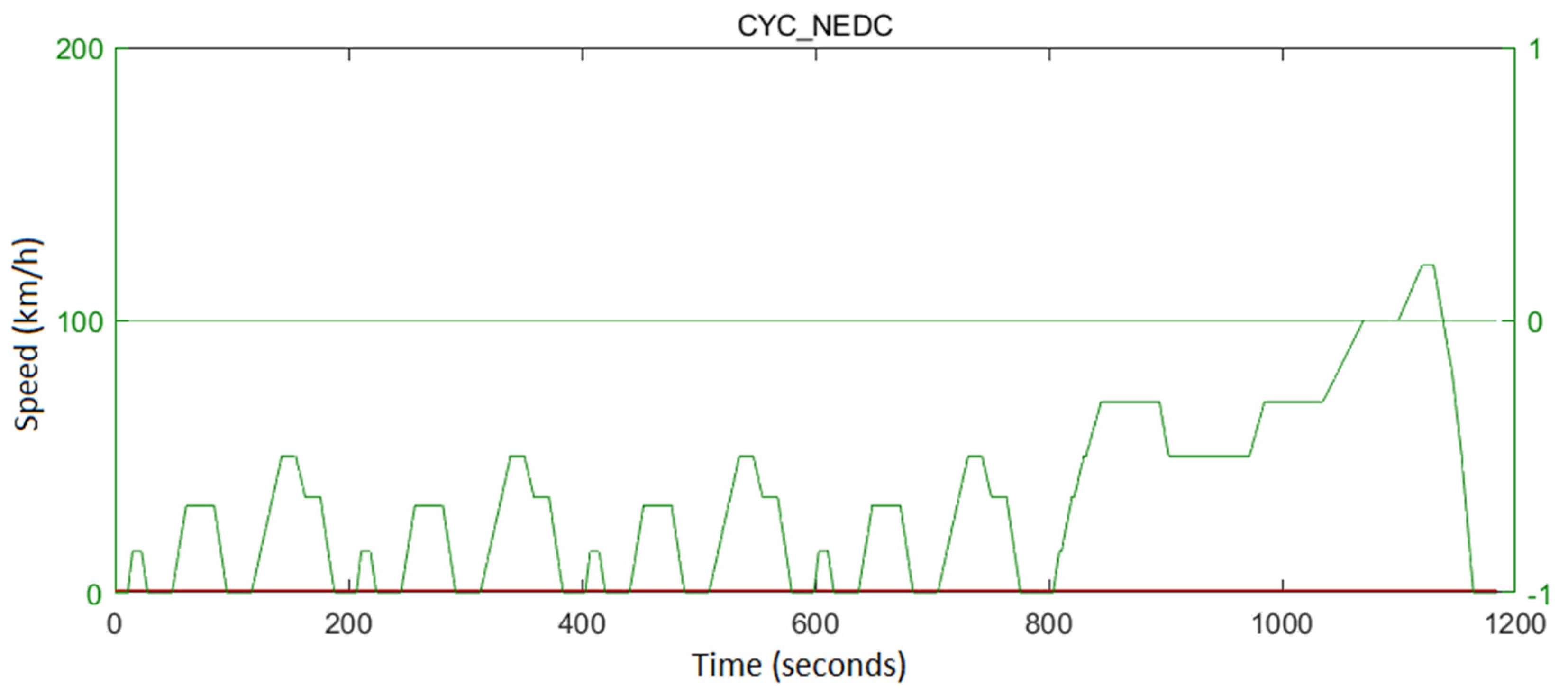
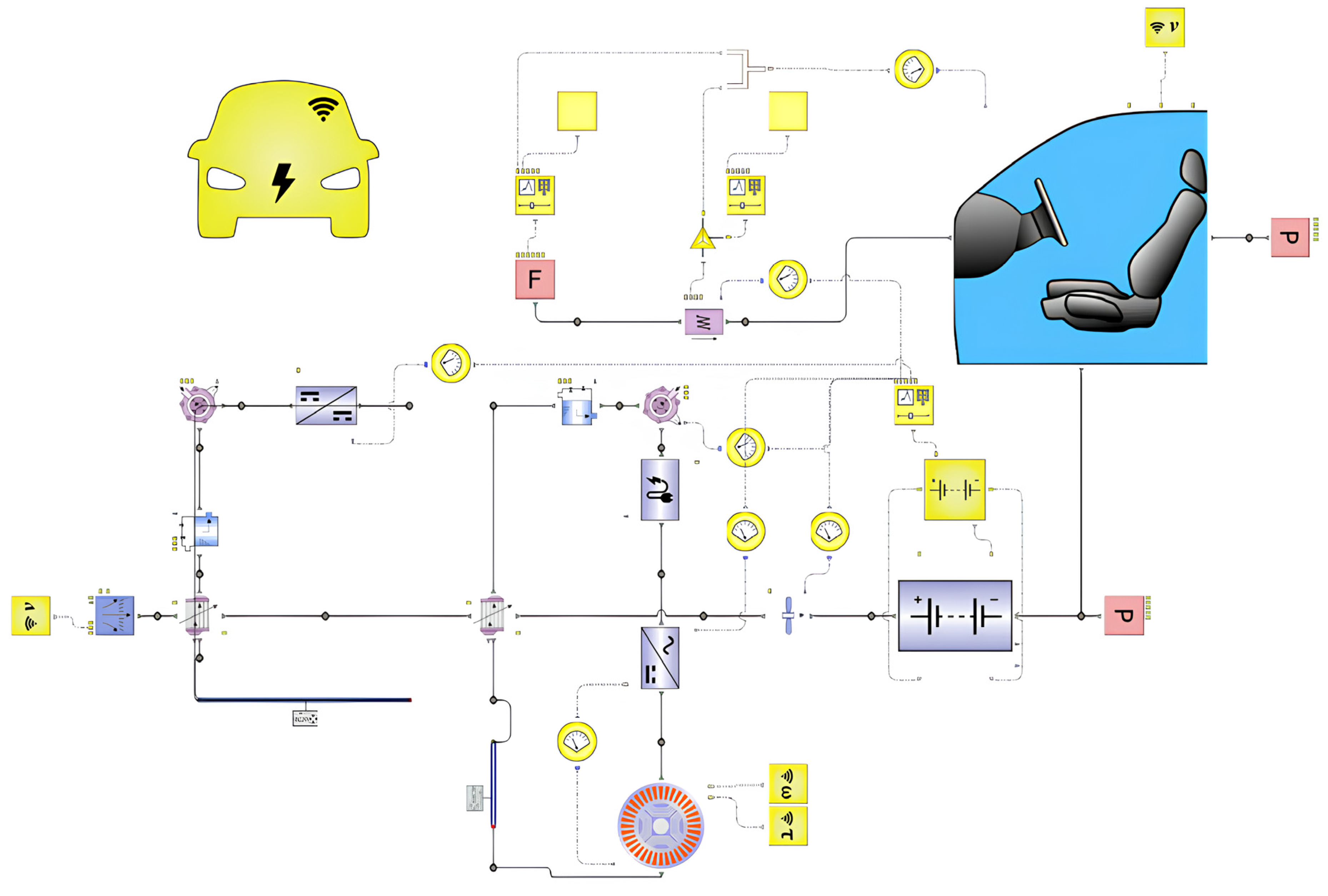
4.1. ADVISOR Simulation Environment
4.2. Siemens Simcenter Flomaster Simulation Environment
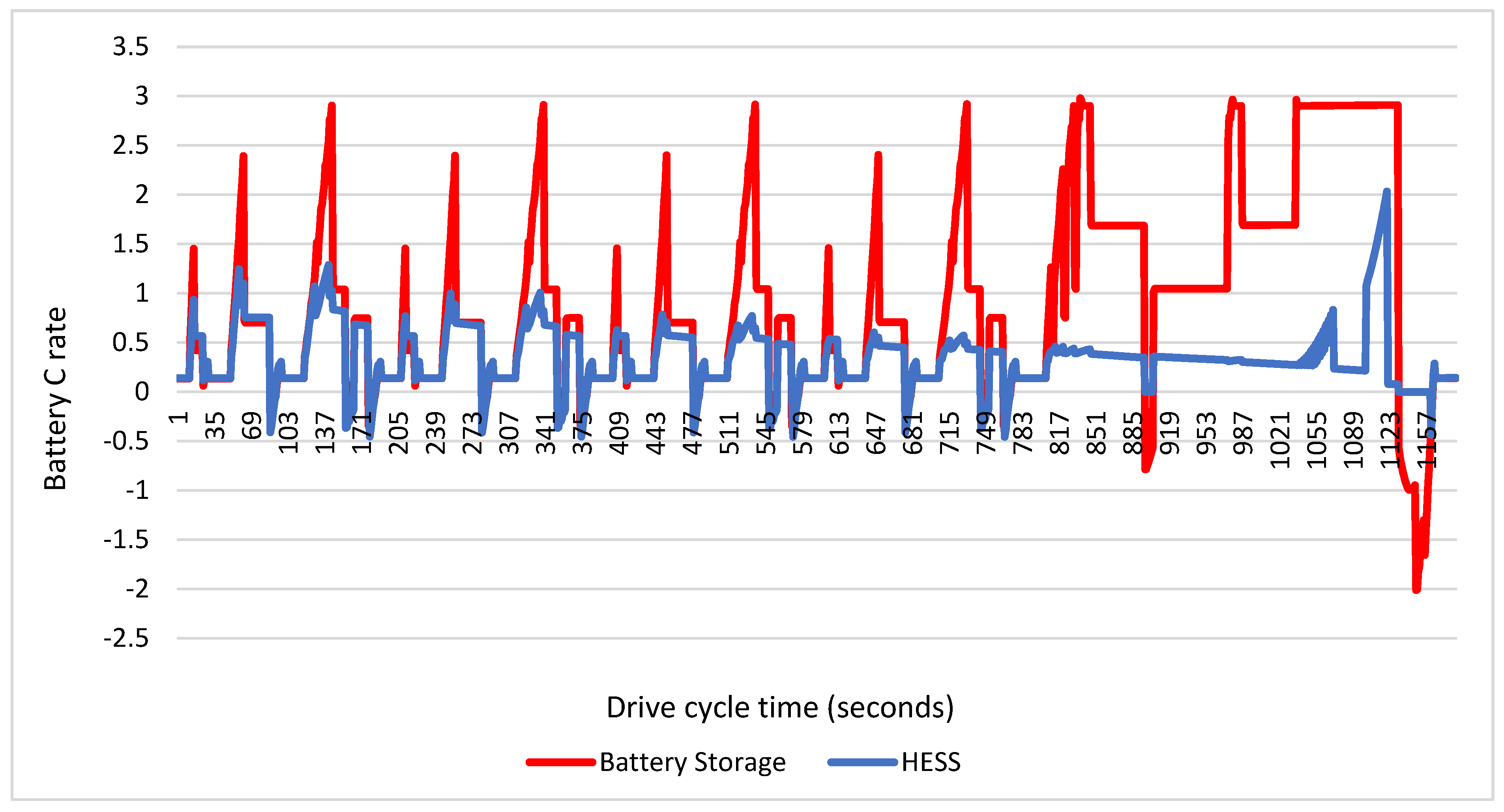
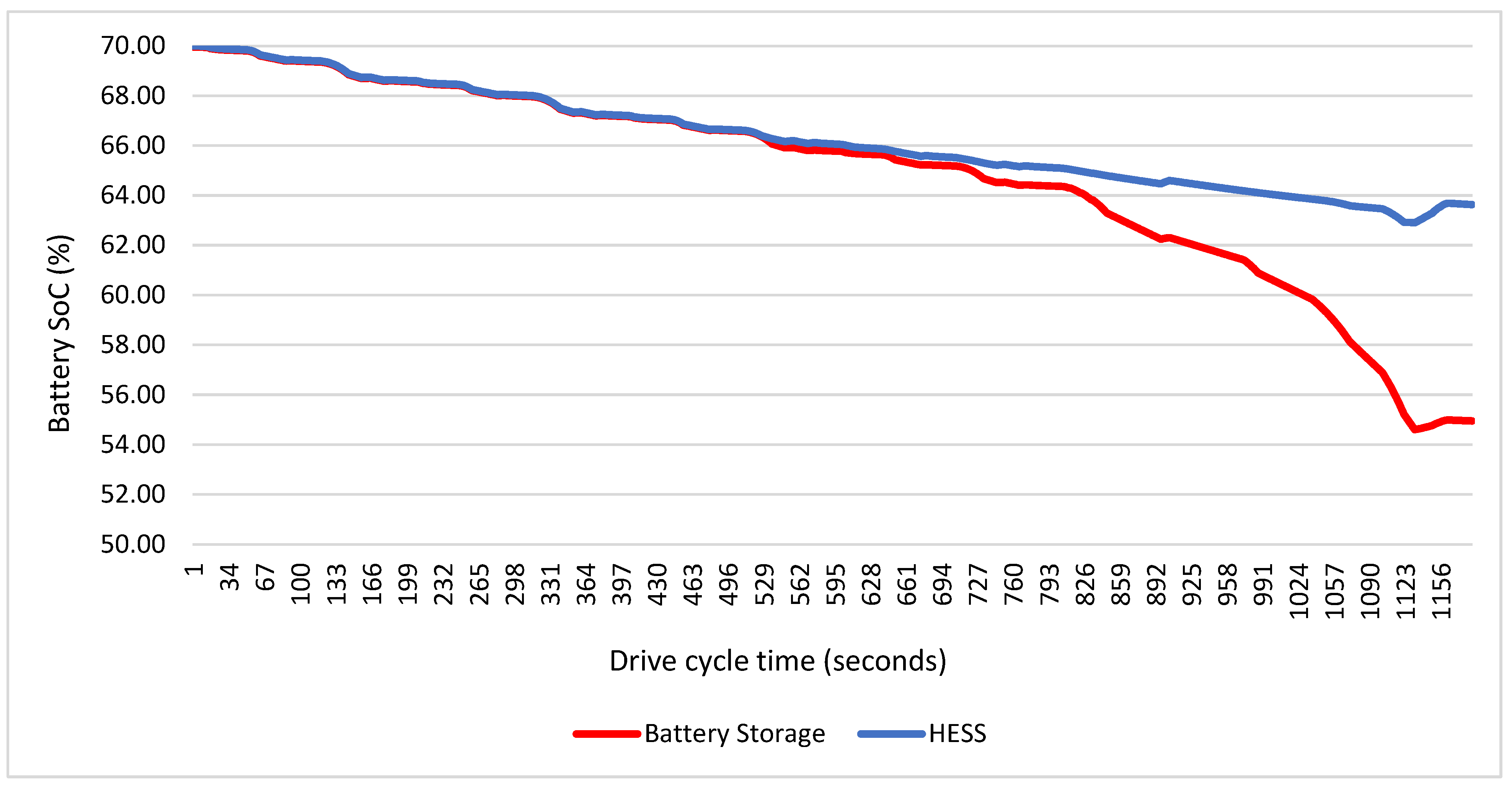
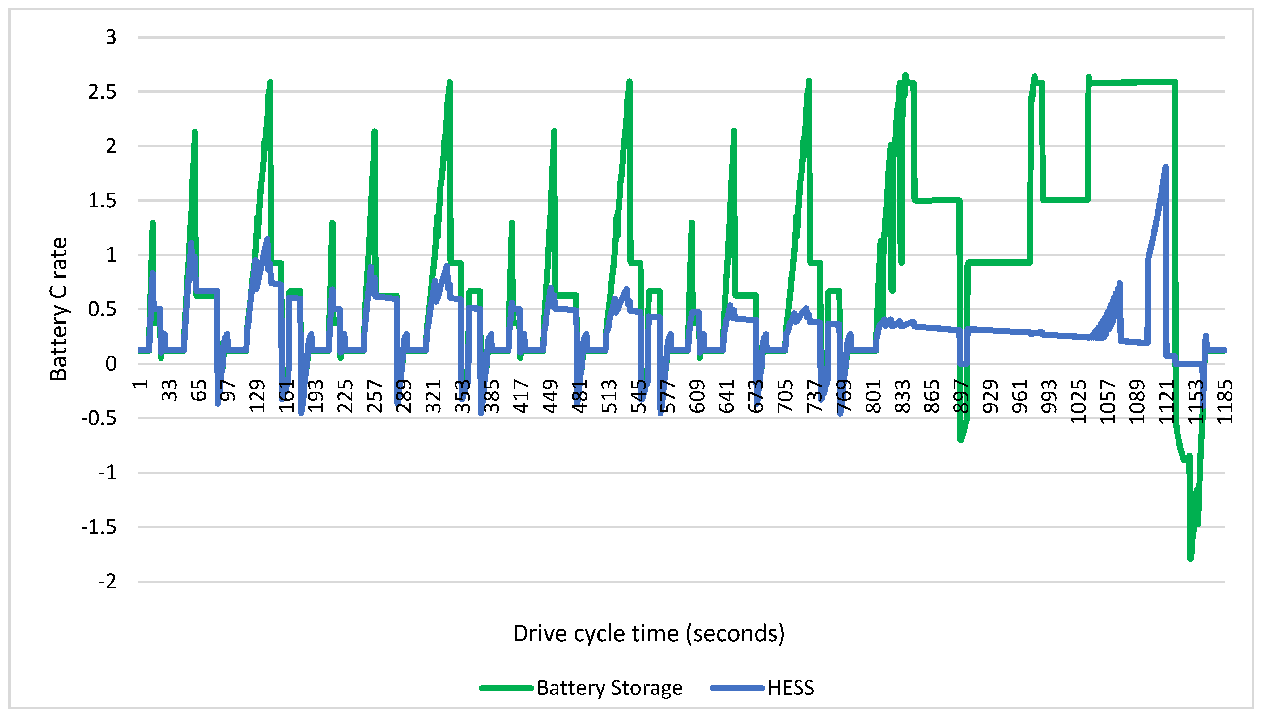
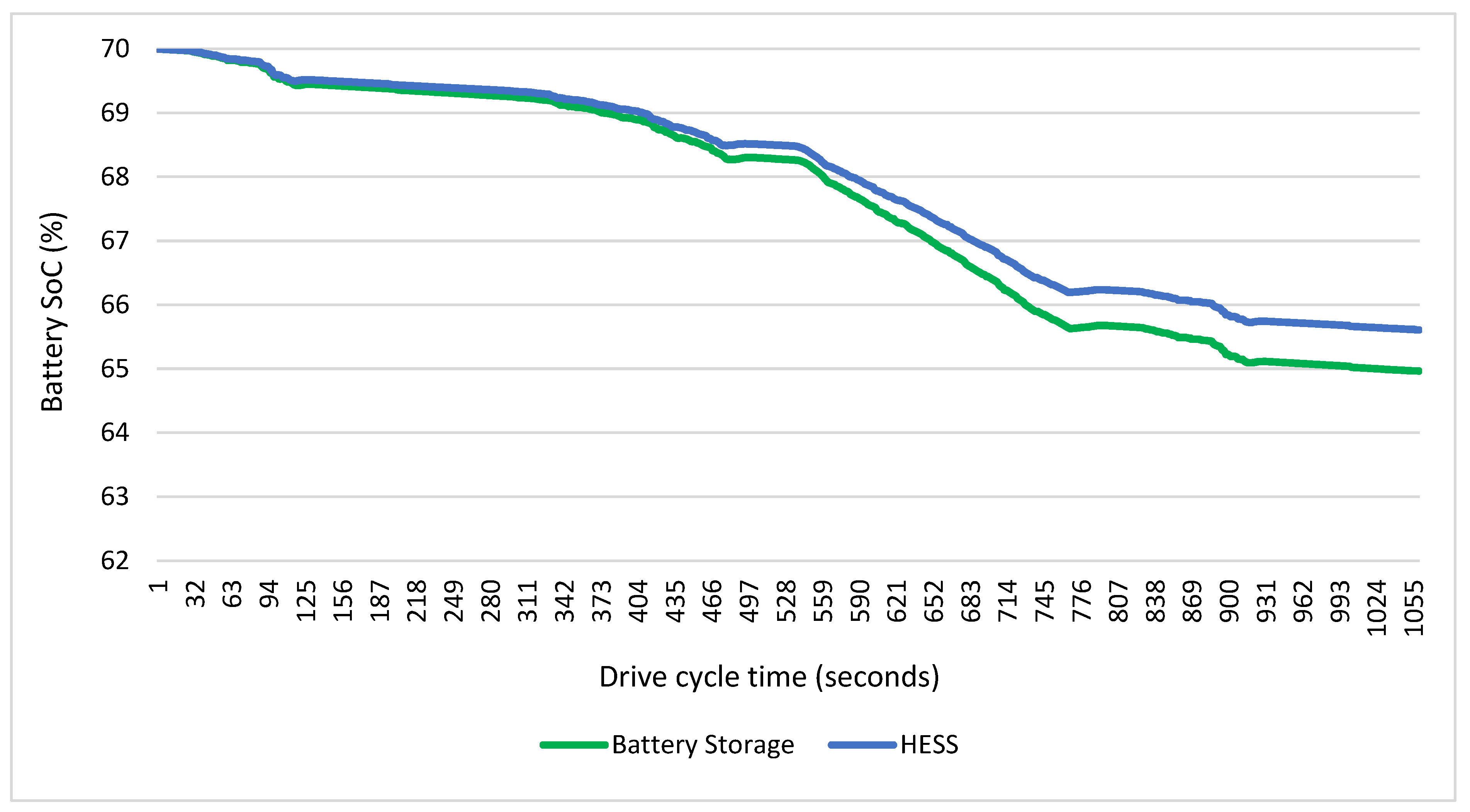
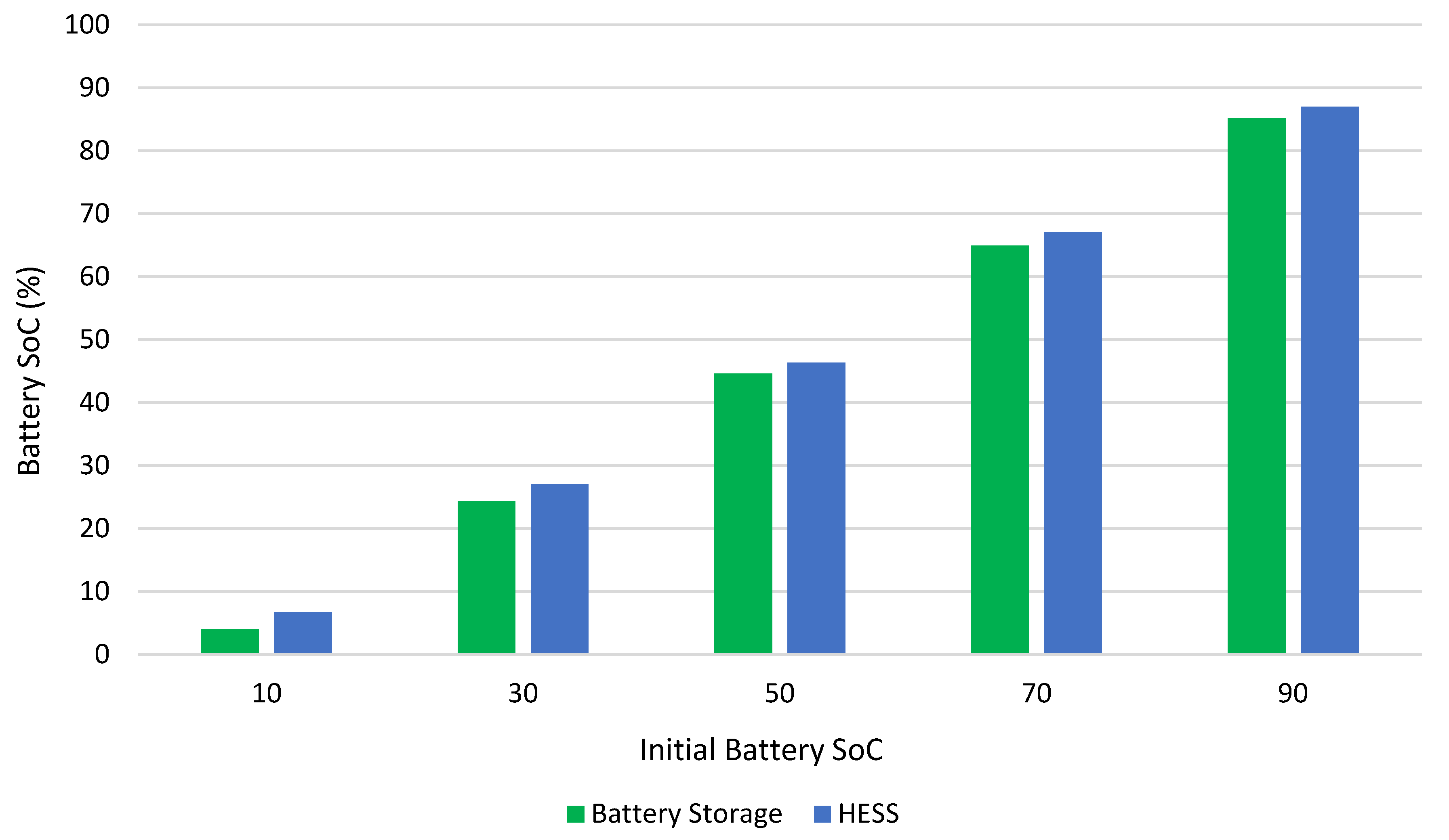
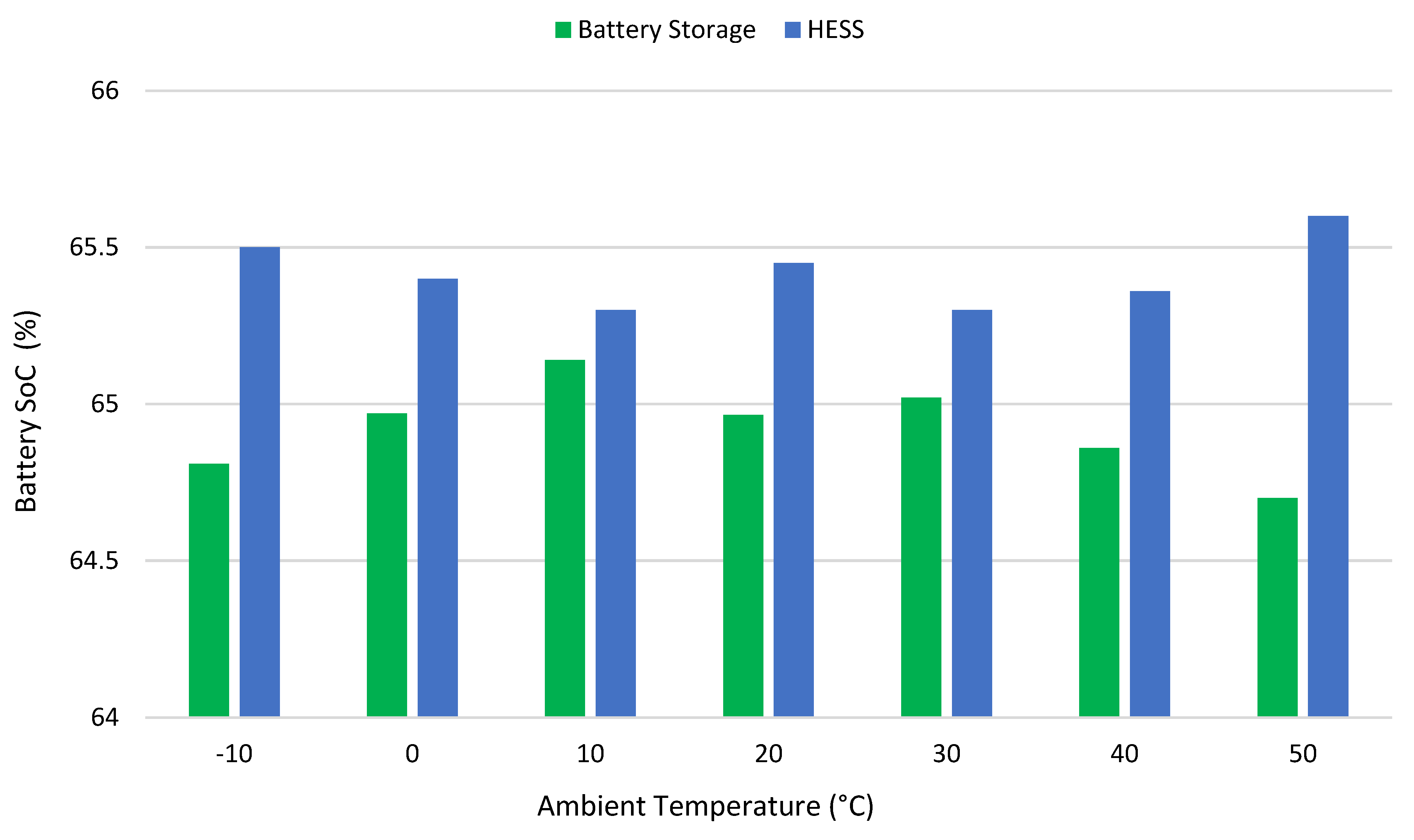
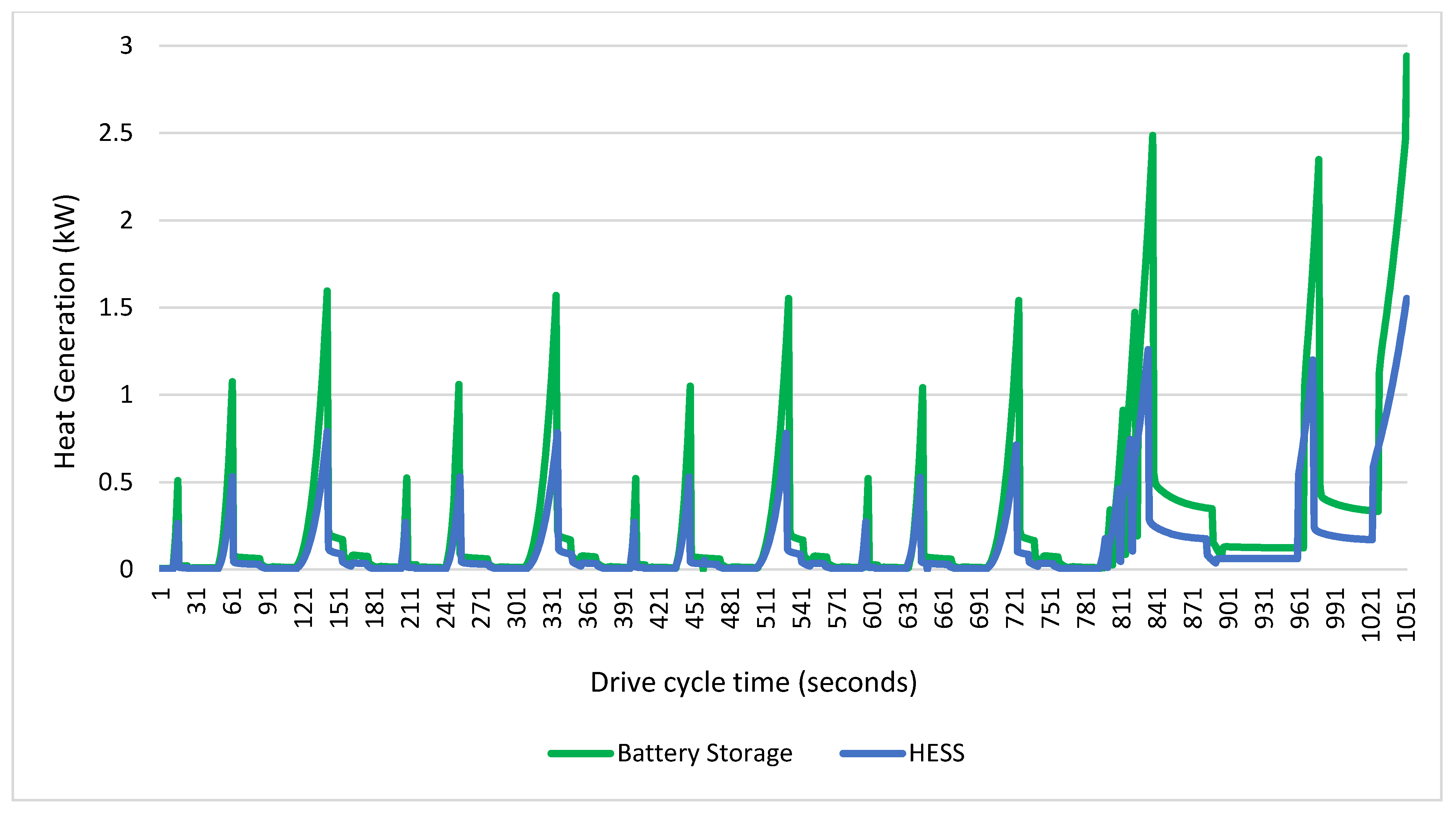
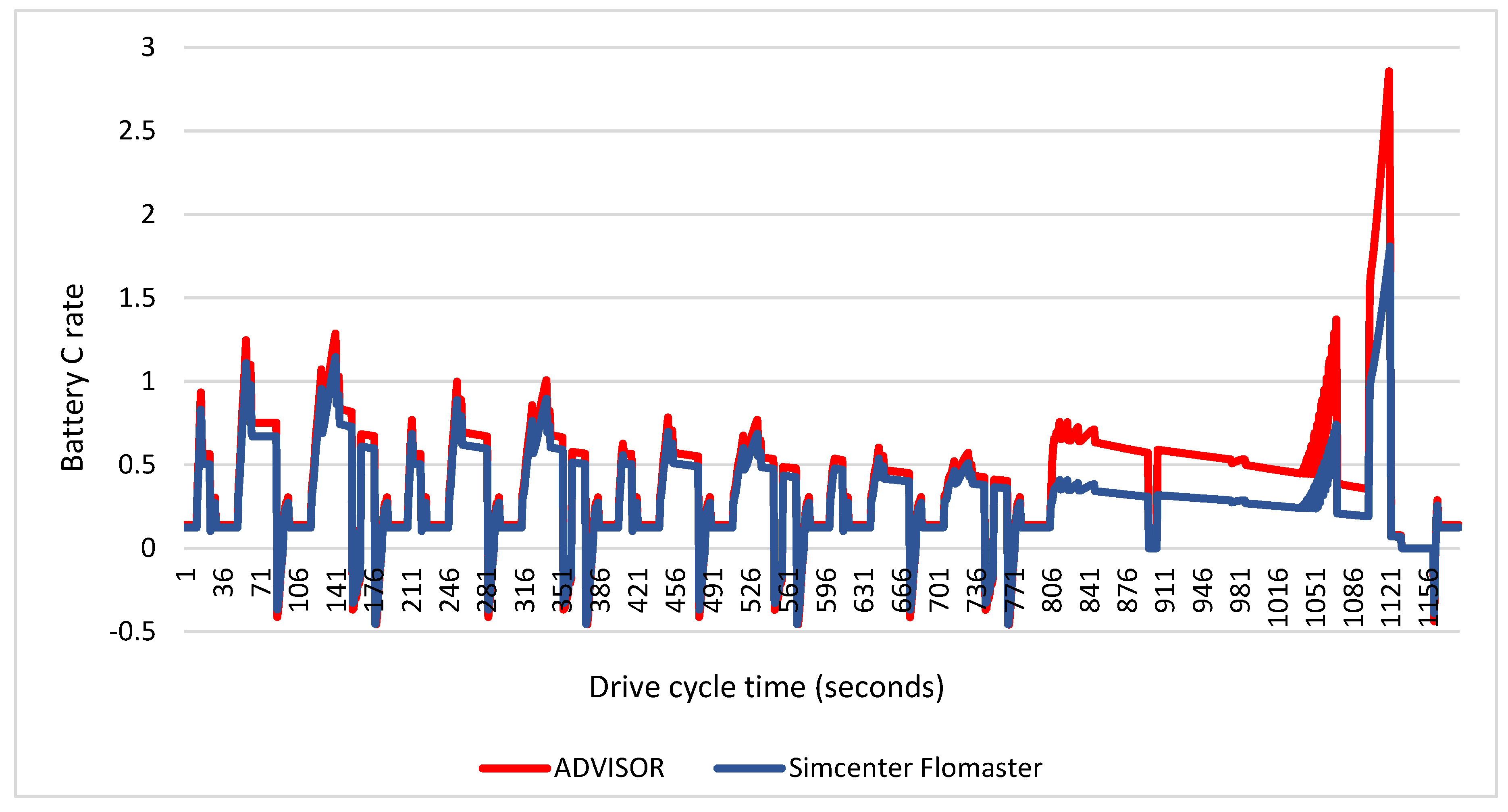
5. Results and Discussion
6. Conclusions
Author Contributions
Funding
Institutional Review Board Statement
Informed Consent Statement
Data Availability Statement
Acknowledgments
Conflicts of Interest
References
- Executive Summary—Global EV Outlook 2022—Analysis. IEA. Available online: https://www.iea.org/reports/global-ev-outlook-2022/executive-summary (accessed on 26 February 2024).
- Global EV Market Share. Statista. Available online: https://www.statista.com/statistics/1371599/global-ev-market-share/ (accessed on 26 February 2024).
- Xu, B.; Sharif, A.; Shahbaz, M.; Dong, K. Have Electric Vehicles Effectively Addressed CO2 Emissions? Analysis of Eight Leading Countries Using Quantile-on-Quantile Regression Approach. Sustain. Prod. Consum. 2021, 27, 1205–1214. [Google Scholar] [CrossRef]
- Road Freight Global Pathways Report. Available online: https://www.mckinsey.com/industries/automotive-and-assembly/our-insights/road-freight-global-pathways-report (accessed on 25 March 2024).
- Prospects for Electric Vehicle Deployment. Available online: https://www.iea.org/reports/global-ev-outlook-2023/prospects-for-electric-vehicle-deployment (accessed on 25 March 2024).
- The Paris Agreement. Available online: https://unfccc.int/process-and-meetings/the-paris-agreement (accessed on 26 February 2024).
- Ishaque, M.R.; Khan, M.A.; Afzal, M.M.; Wadood, A.; Oh, S.-R.; Talha, M.; Rhee, S.-B. Fuzzy Logic-Based Duty Cycle Controller for the Energy Management System of Hybrid Electric Vehicles with Hybrid Energy Storage System. Appl. Sci. 2021, 11, 3192. [Google Scholar] [CrossRef]
- Alanazi, F. Electric Vehicles: Benefits, Challenges, and Potential Solutions for Widespread Adaptation. Appl. Sci. 2023, 13, 6016. [Google Scholar] [CrossRef]
- Yang, H.; Fulton, L. Decoding US Investments for Future Battery and Electric Vehicle Production. Transp. Res. D Transp. Environ. 2023, 118, 103693. [Google Scholar] [CrossRef]
- Deng, J.; Bae, C.; Denlinger, A.; Miller, T. Electric Vehicles Batteries: Requirements and Challenges. Joule 2020, 4, 511–515. [Google Scholar] [CrossRef]
- Lee, G.; Song, J.; Han, J.; Lim, Y.; Park, S. Study on Energy Consumption Characteristics of Passenger Electric Vehicle According to the Regenerative Braking Stages during Real-World Driving Conditions. Energy 2023, 283, 128745. [Google Scholar] [CrossRef]
- Kashkanov, A.; Semenov, A.; Kashkanova, A.; Kryvinska, N.; Palchevskyi, O.; Baraban, S. Estimating the Effectiveness of Electric Vehicles Braking When Determining the Circumstances of a Traffic Accident. Sci. Rep. 2023, 13, 19916. [Google Scholar] [CrossRef] [PubMed]
- Bautista-Montesano, R.; Galluzzi, R.; Mo, Z.; Fu, Y.; Bustamante-Bello, R.; Di, X. Longitudinal Control Strategy for Connected Electric Vehicle with Regenerative Braking in Eco-Approach and Departure. Appl. Sci. 2023, 13, 5089. [Google Scholar] [CrossRef]
- Chidambaram, R.K.; Chatterjee, D.; Barman, B.; Das, P.P.; Taler, D.; Taler, J.; Sobota, T. Effect of Regenerative Braking on Battery Life. Energies 2023, 16, 5303. [Google Scholar] [CrossRef]
- Saiteja, P.; Ashok, B.; Wagh, A.S.; Farrag, M.E. Critical Review on Optimal Regenerative Braking Control System Architecture, Calibration Parameters and Development Challenges for EVs. Int. J. Energy Res. 2022, 46, 20146–20179. [Google Scholar] [CrossRef]
- Liu, H.; Lei, Y.; Fu, Y.; Li, X. Multi-Objective Optimization Study of Regenerative Braking Control Strategy for Range-Extended Electric Vehicle. Appl. Sci. 2020, 10, 1789. [Google Scholar] [CrossRef]
- Keil, P.; Jossen, A. Aging of Lithium-Ion Batteries in Electric Vehicles: Impact of Regenerative Braking. World Electr. Veh. J. 2015, 7, 41–51. [Google Scholar] [CrossRef]
- Kouchachvili, L.; Yaïci, W.; Entchev, E. Hybrid Battery/Supercapacitor Energy Storage System for the Electric Vehicles. J. Power Sources 2018, 374, 237–248. [Google Scholar] [CrossRef]
- Sowe, J.; Varela Barreras, J.; Schimpe, M.; Wu, B.; Candelise, C.; Nelson, J.; Few, S. Model-Informed Battery Current Derating Strategies: Simple Methods to Extend Battery Lifetime in Islanded Mini-Grids. J. Energy Storage 2022, 51, 104524. [Google Scholar] [CrossRef]
- Zhang, L.; Sun, C.; Cai, G.; Koh, L.H. Charging and Discharging Optimization Strategy for Electric Vehicles Considering Elasticity Demand Response. eTransportation 2023, 18, 100262. [Google Scholar] [CrossRef]
- Zhang, M.; Liu, Y.; Li, D.; Cui, X.; Wang, L.; Li, L.; Wang, K. Electrochemical Impedance Spectroscopy: A New Chapter in the Fast and Accurate Estimation of the State of Health for Lithium-Ion Batteries. Energies 2023, 16, 1599. [Google Scholar] [CrossRef]
- Dai, Q.; Kelly, J.C.; Gaines, L.; Wang, M. Life Cycle Analysis of Lithium-Ion Batteries for Automotive Applications. Batteries 2019, 5, 48. [Google Scholar] [CrossRef]
- Garniwa, I.; Orlando, G.; Noorfatima, N.; Sudiarto, B.; Dipantara, B. Study of Battery Performance Analysis with Regenerative Braking Methods Using SIMULINK. J. Phys. Conf. Ser. 2019, 1376, 012027. [Google Scholar] [CrossRef]
- Salek, F.; Resalati, S.; Babaie, M.; Henshall, P.; Morrey, D.; Yao, L. A Review of the Technical Challenges and Solutions in Maximising the Potential Use of Second Life Batteries from Electric Vehicles. Batteries 2024, 10, 79. [Google Scholar] [CrossRef]
- Manzetti, S.; Mariasiu, F. Electric Vehicle Battery Technologies: From Present State to Future Systems. Renew. Sustain. Energy Rev. 2015, 51, 1004–1012. [Google Scholar] [CrossRef]
- Li, J.; Du, Z.; Ruther, R.E.; An, S.J.; David, L.A.; Hays, K.; Wood, M.; Phillip, N.D.; Sheng, Y.; Mao, C.; et al. Toward Low-Cost, High-Energy Density, and High-Power Density Lithium-Ion Batteries. JOM 2017, 69, 1484–1496. [Google Scholar] [CrossRef]
- Ahsan, M.B.F.; Mekhilef, S.; Soon, T.K.; Mubin, M.B.; Shrivastava, P.; Seyedmahmoudian, M. Lithium-ion Battery and Supercapacitor-based Hybrid Energy Storage System for Electric Vehicle Applications: A Review. Int. J. Energy Res. 2022, 46, 19826–19854. [Google Scholar] [CrossRef]
- Guo, L.; Hu, P.; Wei, H. Development of Supercapacitor Hybrid Electric Vehicle. J. Energy Storage 2023, 65, 107269. [Google Scholar] [CrossRef]
- Lemian, D.; Bode, F. Battery-Supercapacitor Energy Storage Systems for Electrical Vehicles: A Review. Energies 2022, 15, 5683. [Google Scholar] [CrossRef]
- Chau, K.T.; Wong, Y.S.; Chan, C.C. An Overview of Energy Sources for Electric Vehicles. Energy Convers. Manag. 1999, 40, 1021–1039. [Google Scholar] [CrossRef]
- Owens, B.B.; Osaka, T. Panel Discussion Future Prospects of Lithium Batteries. J. Power Sources 1997, 68, 173–186. [Google Scholar] [CrossRef][Green Version]
- Gutmann, G. Hybrid Electric Vehicles and Electrochemical Storage Systems—A Technology Push–Pull Couple. J. Power Sources 1999, 84, 275–279. [Google Scholar] [CrossRef]
- Lam, L.T.; Louey, R. Development of Ultra-Battery for Hybrid-Electric Vehicle Applications. J. Power Sources 2006, 158, 1140–1148. [Google Scholar] [CrossRef]
- Shukla, A.K.; Aricò, A.S.; Antonucci, V. An Appraisal of Electric Wieczorek Power Sources. Renew. Sustain. Energy Rev. 2001, 5, 137–155. [Google Scholar] [CrossRef]
- Song, Z.; Li, J.; Hou, J.; Hofmann, H.; Ouyang, M.; Du, J. The Battery-Supercapacitor Hybrid Energy Storage System in Electric Vehicle Applications: A Case Study. Energy 2018, 154, 433–441. [Google Scholar] [CrossRef]
- Zhu, T.; Lot, R.; Wills, R.G.A.; Yan, X. Sizing a Battery-Supercapacitor Energy Storage System with Battery Degradation Consideration for High-Performance Electric Vehicles. Energy 2020, 208, 118336. [Google Scholar] [CrossRef]
- Lei, D.; Gao, Y.; Hou, Z.; Ren, L.; Jiang, M.; Cao, Y.; Zhang, Y.; Wang, J.-G. A Superior Lithium-Ion Capacitor Based on Ultrafine MnO/Dual N-Doped Carbon Anode and Porous Carbon Cathode. Batteries 2023, 9, 241. [Google Scholar] [CrossRef]
- Şen, M.; Yiğiter, M.S.; Özcan, M. Why Are Consumers Switching to Electric Vehicles? Analyzing Consumers Preferences for Electric Vehicles. Case Stud. Transp. Policy 2023, 14, 101108. [Google Scholar] [CrossRef]
- Wieczorek, M.; Lewandowski, M.; Jefimowski, W. Cost comparison of different configurations of a hybrid energy storage system with battery-only and supercapacitor-only storage in an electric city bus. Bull. Pol. Acad. Sci. Tech. Sci. 2019, 67, 1095–1106. [Google Scholar] [CrossRef]
- Abdel Maksoud, M.I.A.; Fahim, R.A.; Shalan, A.E.; Abd Elkodous, M.; Olojede, S.O.; Osman, A.I.; Farrell, C.; Al-Muhtaseb, A.H.; Awed, A.S.; Ashour, A.H.; et al. Advanced Materials and Technologies for Supercapacitors Used in Energy Conversion and Storage: A Review. Environ. Chem. Lett. 2021, 19, 375–439. [Google Scholar] [CrossRef]
- Mariasiu, F.; Kelemen, E.A. Analysis of the Energy Efficiency of a Hybrid Energy Storage System for an Electric Vehicle. Batteries 2023, 9, 419. [Google Scholar] [CrossRef]
- Qi, J.; Su, M. Analysis of Micro-Electric Vehicle with Super Capacitor/Battery Hybrid Energy Storage System. J. Phys. Conf. Ser. 2023, 2459, 012091. [Google Scholar] [CrossRef]
- Lahyani, A.; Sari, A.; Lahbib, I.; Venet, P. Optimal Hybridization and Amortized Cost Study of Battery/Supercapacitors System under Pulsed Loads. J. Energy Storage 2016, 6, 222–231. [Google Scholar] [CrossRef]
- Naseri, F.; Karimi, S.; Farjah, E.; Schaltz, E. Supercapacitor Management System: A Comprehensive Review of Modeling, Estimation, Balancing, and Protection Techniques. Renew. Sustain. Energy Rev. 2022, 155, 111913. [Google Scholar] [CrossRef]
- Lakshmi, K.C.S.; Vedhanarayanan, B. High-Performance Supercapacitors: A Comprehensive Review on Paradigm Shift of Conventional Energy Storage Devices. Batteries 2023, 9, 202. [Google Scholar] [CrossRef]
- He, X.; Zhang, X. A Comprehensive Review of Supercapacitors: Properties, Electrodes, Electrolytes and Thermal Management Systems Based on Phase Change Materials. J. Energy Storage 2022, 56, 106023. [Google Scholar] [CrossRef]
- Subramanian, M.; Solomon, J.M.; Raja, V.; Stanislaus Arputharaj, B.; Shaik, S.; Saleel, C.A.; Alwetaishi, M.; Cuce, E. Experimental Studies and Comprehensive Computational Investigations on Composites-Based Phase Change Material for Battery Thermal Management Systems in Electric Vehicles. J. Energy Storage 2024, 82, 110471. [Google Scholar] [CrossRef]
- Berjoza, D.; Pirs, V.; Jurgena, I. Research into the Regenerative Braking of an Electric Car in Urban Driving. World Electr. Veh. J. 2022, 13, 202. [Google Scholar] [CrossRef]
- Gao, Y.; Jiang, J.; Zhang, C.; Zhang, W.; Jiang, Y. Aging Mechanisms under Different State-of-Charge Ranges and the Multi-Indicators System of State-of-Health for Lithium-Ion Battery with Li(NiMnCo)O2 Cathode. J. Power Sources 2018, 400, 641–651. [Google Scholar] [CrossRef]
- Makki, M.; Lee, C.W.; Ayoub, G. Stress Distribution Inside a Lithium-Ion Battery Cell during Fast Charging and Its Effect on Degradation of Separator. Batteries 2023, 9, 502. [Google Scholar] [CrossRef]
- Collath, N.; Tepe, B.; Englberger, S.; Jossen, A.; Hesse, H. Aging Aware Operation of Lithium-Ion Battery Energy Storage Systems: A Review. J. Energy Storage 2022, 55, 105634. [Google Scholar] [CrossRef]
- Şahin, M.E.; Blaabjerg, F.; Sangwongwanich, A. A Comprehensive Review on Supercapacitor Applications and Developments. Energies 2022, 15, 674. [Google Scholar] [CrossRef]
- Rehman, J.; Eid, K.; Ali, R.; Fan, X.; Murtaza, G.; Faizan, M.; Laref, A.; Zheng, W.; Varma, R.S. Engineering of Transition Metal Sulfide Nanostructures as Efficient Electrodes for High-Performance Supercapacitors. ACS Appl. Energy Mater. 2022, 5, 6481–6498. [Google Scholar] [CrossRef]
- Raghavendra, K.V.G.; Vinoth, R.; Zeb, K.; Muralee Gopi, C.V.V.; Sambasivam, S.; Kummara, M.R.; Obaidat, I.M.; Kim, H.J. An Intuitive Review of Supercapacitors with Recent Progress and Novel Device Applications. J. Energy Storage 2020, 31, 101652. [Google Scholar] [CrossRef]
- Daraz, A.; Khan, I.A.; Basit, A.; Malik, S.A.; AlQahtani, S.A.; Zhang, G. Frequency Regulation of Interconnected Hybrid Power System with Assimilation of Electrical Vehicles. Heliyon 2024, 10, e28073. [Google Scholar] [CrossRef]
- Turkmen, A.C.; Solmaz, S.; Celik, C. Analysis of Fuel Cell Vehicles with Advisor Software. Renew. Sustain. Energy Rev. 2017, 70, 1066–1071. [Google Scholar] [CrossRef]
- Mitra, U.; Arya, A.; Gupta, S. Comparative Analysis of Hybrid Electric Vehicle on Different Performance Metrics Using ADVISOR 2.0. In Power Engineering and Intelligent Systems; Lecture Notes in Electrical Engineering; Springer Nature Singapore: Singapore, 2024; pp. 153–167. [Google Scholar]
- Sileghem, L.; Bosteels, D.; May, J.; Favre, C.; Verhelst, S. Analysis of Vehicle Emission Measurements on the New WLTC, the NEDC and the CADC. Transp. Res. D Transp. Environ. 2014, 32, 70–85. [Google Scholar] [CrossRef]
- Garrido-Silva, G.; Maradey-Lazaro, J.G.; Rincón-Quintero, A.D.; Lengerke-Pérez, O.; Sandoval-Rodriguez, C.L.; Cardenas-Arias, C.G. Estimation of the Energy Consumption of an Electric Utility Vehicle: A Case Study. In Recent Advances in Electrical Engineering, Electronics and Energy; Lecture Notes in Electrical Engineering; Springer International Publishing: Cham, Switzerland, 2021; pp. 257–272. [Google Scholar]
- Martyushev, N.V.; Malozyomov, B.V.; Khalikov, I.H.; Kukartsev, V.A.; Kukartsev, V.V.; Tynchenko, V.S.; Tynchenko, Y.A.; Qi, M. Review of Methods for Improving the Energy Efficiency of Electrified Ground Transport by Optimizing Battery Consumption. Energies 2023, 16, 729. [Google Scholar] [CrossRef]
- Bai, Z.; Yan, Z.; Wu, X.; Xu, J.; Cao, B. H∞ Control for Battery/Supercapacitor Hybrid Energy Storage System Used in Electric Vehicles. Int. J. Automot. Technol. 2019, 20, 1287–1296. [Google Scholar] [CrossRef]
- Da Silva, S.F.; Eckert, J.J.; Corrêa, F.C.; Silva, F.L.; Silva, L.C.A.; Dedini, F.G. Dual HESS Electric Vehicle Powertrain Design and Fuzzy Control Based on Multi-Objective Optimization to Increase Driving Range and Battery Life Cycle. Appl. Energy 2022, 324, 119723. [Google Scholar] [CrossRef]


| EV Parameters | Parameter Values |
|---|---|
| Battery cell voltage | 4.2 V |
| Battery pack voltage | 400 V |
| Battery capacity | 52.4 kWh |
| Battery cell quantity | 4560 |
| Battery weight | 340 kg |
| Engine power | 218 HP |
| Average consumption | 16.9 kWh/100 km |
| Scenarios | Driver | Drive + 1 | Drive + 2 | Full Load |
|---|---|---|---|---|
| Scenario 1 | 1.558 C | 1.618 C | 1.678 C | 2.275 C |
| Scenario 2 | 0.710 C | 0.738 C | 0.765 C | 1.037 C |
| Scenario 3 | 1.277 C | 1.326 C | 1.376 C | 1.866 C |
| SC Parameters | Parameter Values |
|---|---|
| SC cell voltage | 2.7 V |
| SC pack voltage | 400 V |
| Continuous cell current | 40 A (for 40 °C) |
| Maximum cell current | 170 A |
| Internal resistance | 0.0032 Ω |
| Total weight | 27 kg |
| Total capacity | 159.3 Wh |
| Total cost | $3000 |
| No | Fuzzy Logic Input Parameters | Fuzzy Logic Output Parameters | ||||
|---|---|---|---|---|---|---|
| Temperature (°C) | Cell C Rate | Battery SoC (%) | SC SoC (%) | Battery Rate (%) | SC Rate (%) | |
| 1 | 34 | 0.395 | 13 | 93 | 62.5 | 37.5 |
| 2 | −16 | 1.594 | 47 | 17 | 0 | 100 |
| 3 | −7 | 0.439 | 12 | 28 | 37.5 | 62.5 |
| . | . | . | . | . | . | . |
| . | . | . | . | . | . | . |
| . | . | . | . | . | . | . |
| 999 | 47 | 0.458 | 15 | 100 | 100 | 0 |
| 1000 | −5 | 0.544 | 6 | 86 | 75 | 25 |
| Input Values and Levels | Border Points | ||||
|---|---|---|---|---|---|
| A | B | C | D | ||
| Temperature (°C) | L | −30 | −15 | 5 | 15 |
| N | 5 | 15 | 45 | 55 | |
| H | 43 | 70 | 90 | 110 | |
| Cell C rate | L | - | - | 0.08 | 0.15 |
| N | 0.1 | 0.2 | 0.5 | 0.65 | |
| H | 0.45 | 0.75 | 1.5 | 2 | |
| Battery SoC (%) | L | - | - | 0 | 25 |
| N | 10 | 20 | 80 | 90 | |
| H | 75 | 90 | 100 | - | |
| SC SoC (%) | L | - | - | 0 | 10 |
| N | 5 | 15 | 85 | 95 | |
| H | 80 | 95 | 100 | - | |
| Performance Measure | Performance Value |
|---|---|
| R2 | 0.927 |
| MSE | 0.15 |
| RMSE | 0.39 |
Disclaimer/Publisher’s Note: The statements, opinions and data contained in all publications are solely those of the individual author(s) and contributor(s) and not of MDPI and/or the editor(s). MDPI and/or the editor(s) disclaim responsibility for any injury to people or property resulting from any ideas, methods, instructions or products referred to in the content. |
© 2024 by the authors. Licensee MDPI, Basel, Switzerland. This article is an open access article distributed under the terms and conditions of the Creative Commons Attribution (CC BY) license (https://creativecommons.org/licenses/by/4.0/).
Share and Cite
Şen, M.; Özcan, M.; Eker, Y.R. Fuzzy Logic-Based Energy Management System for Regenerative Braking of Electric Vehicles with Hybrid Energy Storage System. Appl. Sci. 2024, 14, 3077. https://doi.org/10.3390/app14073077
Şen M, Özcan M, Eker YR. Fuzzy Logic-Based Energy Management System for Regenerative Braking of Electric Vehicles with Hybrid Energy Storage System. Applied Sciences. 2024; 14(7):3077. https://doi.org/10.3390/app14073077
Chicago/Turabian StyleŞen, Mehmet, Muciz Özcan, and Yasin Ramazan Eker. 2024. "Fuzzy Logic-Based Energy Management System for Regenerative Braking of Electric Vehicles with Hybrid Energy Storage System" Applied Sciences 14, no. 7: 3077. https://doi.org/10.3390/app14073077
APA StyleŞen, M., Özcan, M., & Eker, Y. R. (2024). Fuzzy Logic-Based Energy Management System for Regenerative Braking of Electric Vehicles with Hybrid Energy Storage System. Applied Sciences, 14(7), 3077. https://doi.org/10.3390/app14073077