Communication

Efficient Method for Identifying Key Errors Based on 21-Geometric-Error Measurement of Three Linear Axes of Machine Tools

Key Lab of Luminescence and Optical Information, Ministry of Education, Beijing Jiaotong University, Beijing 100044, China
*
Author to whom correspondence should be addressed.
Appl. Sci. 2024, 14(7), 2982; https://doi.org/10.3390/app14072982
Submission received: 1 March 2024 / Revised: 28 March 2024 / Accepted: 31 March 2024 / Published: 2 April 2024
(This article belongs to the Special Issue Advances in Optical Instrument and Measurement Technology)

Abstract

:
Key errors of machine tools have a significant impact on their accuracy, however accurately and quickly measuring the geometric errors of machine tools is essential for key error identification. Fortunately, a quick and direct laser measurement method and system for 21 geometric errors of three linear axes of machine tools were proposed previously, which enables the measurement of all 21 geometric errors via a one-step installation and a three-step automated measurement process. Based on this, to efficiently identify the key error factors, this paper first utilizes the 21 geometric errors obtained from the proposed measurement system to evaluate the contribution of each error to the volumetric errors of machine tools, leading to the building of a 21-geometric-error sensitivity analysis model. Then, experiments are carried out on the vertical machining tool TH5656, and all 21 geometric errors are obtained in 5 min. After this, the volumetric error distribution in the machining workspace is mapped according to the relationship between the geometric errors and the machining errors, and the key error factors affecting the manufacturing and machining accuracy of the TH5656 are ultimately determined. Thus, this new method provides a way to quickly identify key errors of the three linear axes of machine tools, and offers guidance for the machine tool configuration design, machining technology determination, and geometric error compensation.

1. Introduction

The computer numerical control (CNC) machine tool is the cornerstone of the modern manufacturing industry, often referred to as the “industrial mother machine”. The level of machining accuracy plays a pivotal role in evaluating its performance. To enhance and uphold machining accuracy throughout the manufacturing and usage phases, it is imperative to undertake precise measurements of various errors inherent in machine tools. By establishing error models and implementing error compensation, the aim is to improve and sustain the machining accuracy. This approach has emerged as a significant trend in improving machine tool accuracy [1,2,3].
The primary error sources in machine tools include geometric errors, thermal errors, cutting force errors, etc. [4]. According to Ramesh [5], geometric errors are the predominant factors contributing to machining errors, making the measurement and modeling of these errors critical for improving machine tool accuracy. Currently, homogeneous coordinate transformation is often employed to determine the volumetric errors of machine tools, and the error compensation model is well developed [6]. Consequently, the measurement of geometric errors is essential for improving the manufacturing and machining accuracy of machine tools.
Table 1 illustrates a total of 21 geometric errors that require measurement for the three linear axes of machine tools [5]. Presently, the laser interferometer is widely employed as it offers high measurement accuracy at a relatively low cost. However, it is a single-parameter measurement instrument, requiring the replacement of different optical attachments and readjustment of the optical path for each error measurement. This process is time-consuming and labor-intensive, leading to low measurement efficiency. Moreover, it falls short of achieving a full-parameter measurement. Thus, to reduce the economic and time costs required for error compensation and to improve the efficiency of error compensation in machine tools, researchers have conducted studies from two aspects.
On the one hand, various measurement methods with multiple parameters have been proposed to improve the measurement efficiency. Indirect measurement methods have been explored, such as utilizing a ball bar [7], a planar orthogonal grating [8], a workpiece testing method [9], or a laser tracking interferometer [10]. While indirect measurement methods offer higher measurement efficiency, it is important to note that they may provide relatively lower accuracy compared to the laser interferometers. Direct measurement methods primarily focus on assessing the geometric errors of a single linear axis. For example, Lee [11] used a one-dimensional grating to simultaneously measure the six-degrees-of-freedom geometric errors of a linear axis. Cai [12] proposed the use of a semiconductor laser as a light source to measure position error by laser interferometry, and other geometric errors are obtained by laser collimation. Similar measurement methods were proposed by Liu [13]. Yu [14] utilized a reflection grating encoder to achieve simultaneous measurement of dual-channel six-degree-of-freedom errors. Zhou [15] employed a dual optical frequency comb to measure multiple geometric errors. These direct methods have not yet been developed into commercial instruments, while the main commercial instruments available are the laser 5D/6D measuring instruments by API and the XM-60 measuring instrument by Renishaw. However, these direct measurement methods and instruments still cannot directly obtain the 21 geometric errors of the three linear axes of machine tools.
On the other hand, a sensitivity analysis has been employed to identify the key geometric error factors that have a significant impact on machine tool accuracy. Once these key factors are determined, they can be measured and compensated, thereby reducing the number of geometric errors that require measurement and improving error compensation efficiency. This approach is known as key error identification, which focuses on studying the influence of error elements on machine tool accuracy and serves as the basis for machine tool design and manufacturing. Li [16] utilized measurement error data and error modeling to identify key errors in three-axis CNC machine tools. Cheng [17] proposed a sensitivity coefficient model for 3-RPS symmetrical parallel robot leg based on a normalized description. Yang [18] developed a rapid modeling and compensation method for volumetric errors using the global sensitivity analysis method. Although these methods ultimately reduce the number of errors that need to be measured, it is still necessary to obtain the 21 geometric errors before identifying the key geometric error elements. Therefore, the rapid and high-precision acquisition of the 21 geometric errors of the three linear axes plays a crucial role in conducting critical error identification and subsequent error compensation.
We have proposed direct methods for simultaneously measuring six-degree-of-freedom geometric errors of linear guides [19,20]. Based on these, we first proposed a 21-geometric-error measurement method and system for the three linear axes with one-step installation and developed a measurement system, which enabled the direct, rapid, and high-precision acquisition of all 21 geometric errors [21]. Thus, to efficiently identify the key error factors that have a significant impact on machine tool accuracy, this paper first utilizes the 21 geometric errors obtained from the developed measurement system to determine the volumetric errors of the machine tool. Then, a sensitivity analysis model for these 21 geometric errors is built based on the global sensitivity analysis method. Finally, experimental measurements of the 21 geometric errors for the three linear axes of the vertical machining tool TH5656 were conducted, achieving the rapid and accurate identification of the key error factors.

2. Sensitivity Analysis for 21 Geometric Errors of Three Linear Axes of Machine Tools

The 21 geometric errors of the three linear axes of machine tools can be obtained through a one-step installation and three-step automated measurement process using our previously developed measurement system [21]. Once these 21 geometric errors are determined, it becomes possible to establish the error compensation model using a homogeneous coordinate transformation matrix. By synthesizing error elements, the volumetric errors of the machine tool can be determined, which refers to the maximum deviation between the actual and ideal positions of a cutting tool in the X-, Y-, and Z-directions of a machining workspace. Take a typical vertical machine tool as an example. Its model for volumetric errors (Δx, Δy, Δz) in the X-, Y-, and Z-directions is given by [22]:
Δ x = δ x ( X ) δ x ( Y ) + δ x ( Z ) y ε z ( X ) z ε y ( X ) z ε y ( Y ) + y S X Y + z S X Z Δ y = δ y ( X ) δ y ( Y ) + δ y ( Z ) + z ε x ( X ) + z ε x ( Y ) z S y Z Δ z = δ z ( X ) δ z ( Y ) + δ z ( Z ) + y ε x ( X )
To identify the key geometric error elements that have a significant impact on machine accuracy, a sensitivity analysis of the 21 geometric error elements is conducted based on the global sensitivity analysis method [18]. This involves calculating the partial derivatives of the volumetric errors (Δx, Δy, Δz) with respect to each of the 21 geometric error elements, resulting in the derivation of a sensitivity coefficient matrix K for volumetric errors
K = Δ x δ x ( X ) Δ x δ y ( X ) Δ x S X Y Δ x S X Z Δ x S Y Z Δ y δ x ( X ) Δ y δ y ( X ) Δ y S X Y Δ y S X Z Δ y S Y Z Δ z δ x ( X ) Δ z δ y ( X ) Δ z S X Y Δ z S X Z Δ z S Y Z
wherein the six-degree-of-freedom geometric errors for the X-, Y-, and Z-axes, as well as the three squareness errors from left to right are represented. The order of the six errors is position error, horizontal straightness, vertical straightness, pitch, yaw, and roll. Next, substituting Equation (1) into Equation (2) yields a sensitivity coefficient matrix:
K = 1 0 0 y z 0 0 1 0 0 0 z 0 0 1 0 0 0 y z 0 0 1 0 0 0 z 1 0 0 0 z 0 0 1 0 0 0 0 0 0 z 0 0 1 0 0 y 0 0 1 0 0 0 1 0 0 0 0 0 0 0 0
The matrix K signifies the contribution of each geometric error on the volumetric errors of the machine tools. A higher sensitivity coefficient for a specific error element indicates that the volumetric error is more responsive to that particular error element, thus suggesting its significance as a key geometric error element impacting machining accuracy. To assess the relative impact of each geometric error element on the volumetric errors, the sensitivity coefficients are normalized in X-, Y-, and Z-directions, respectively:
k xi = K xi K xi ,   k y i = K y i K y i ,   k z i = K z i K z i
The magnitude of volumetric errors caused by the geometric error elements is not solely determined by their sensitivity coefficients, but also by their magnitudes. Geometric error elements with higher sensitivity coefficients, controlled at lower levels during machine tool design and assembly, can lead to reduced volumetric errors. Hence, this paper employs multiplication to comprehensively evaluate the contribution of each geometric error element on volumetric errors by calculating the product of the sensitivity coefficient and error magnitude
E xi = k xi Δ e i k xi Δ e i E yi = k yi Δ e i k yi Δ e i E zi = k zi Δ e i k zi Δ e i ,   i = 1 , 2 , 21
wherein Exi, Eyi, and Ezi represent the influence factors of the error element ei on the volumetric errors of machine tools in the X-, Y-, and Z-directions, respectively. Δei represents the error magnitude. A higher influence factor indicates a stronger impact of the geometric error on volumetric errors, thus identifying it as a key geometric error.

3. Experimental Results and Analysis

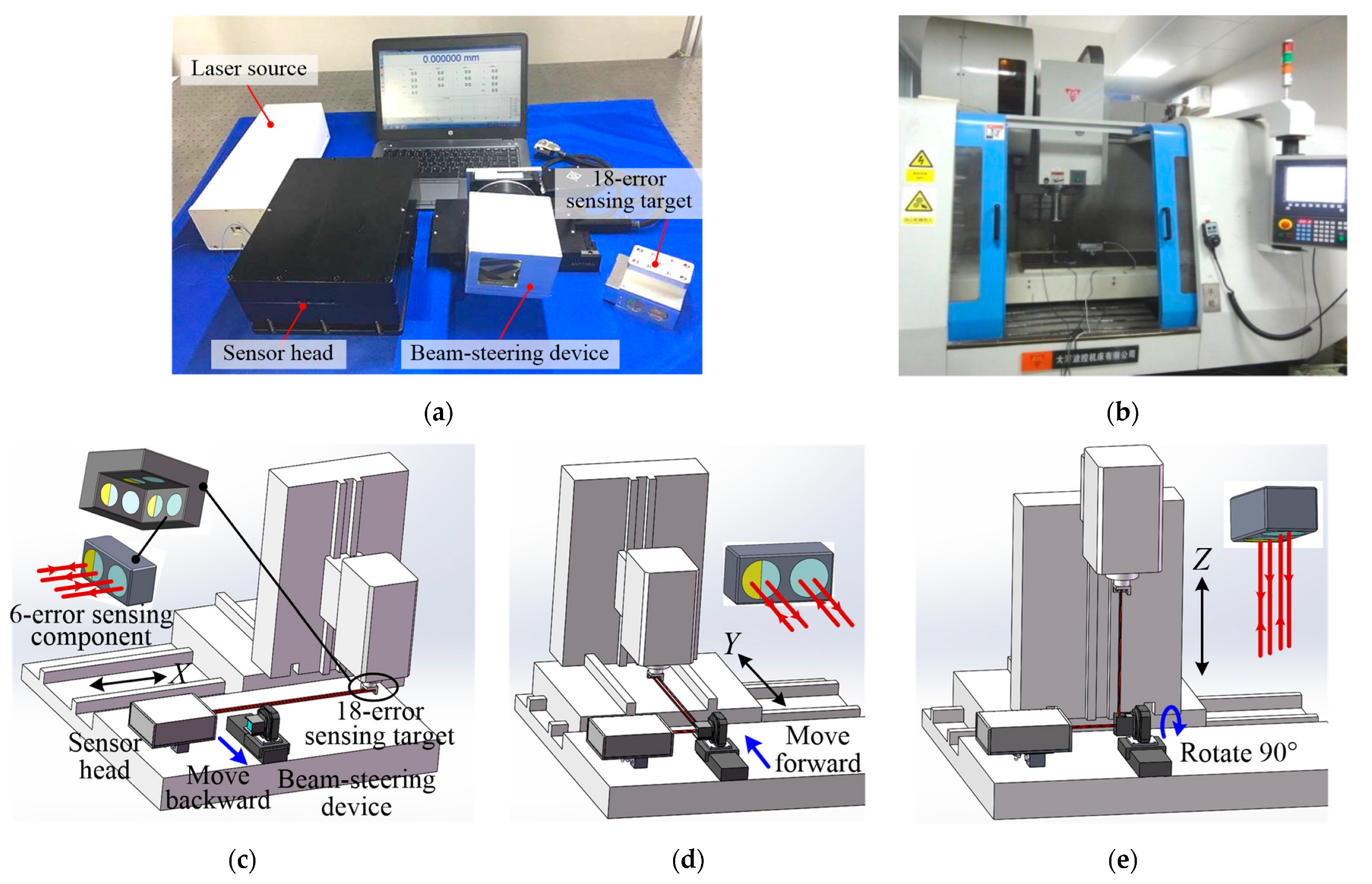
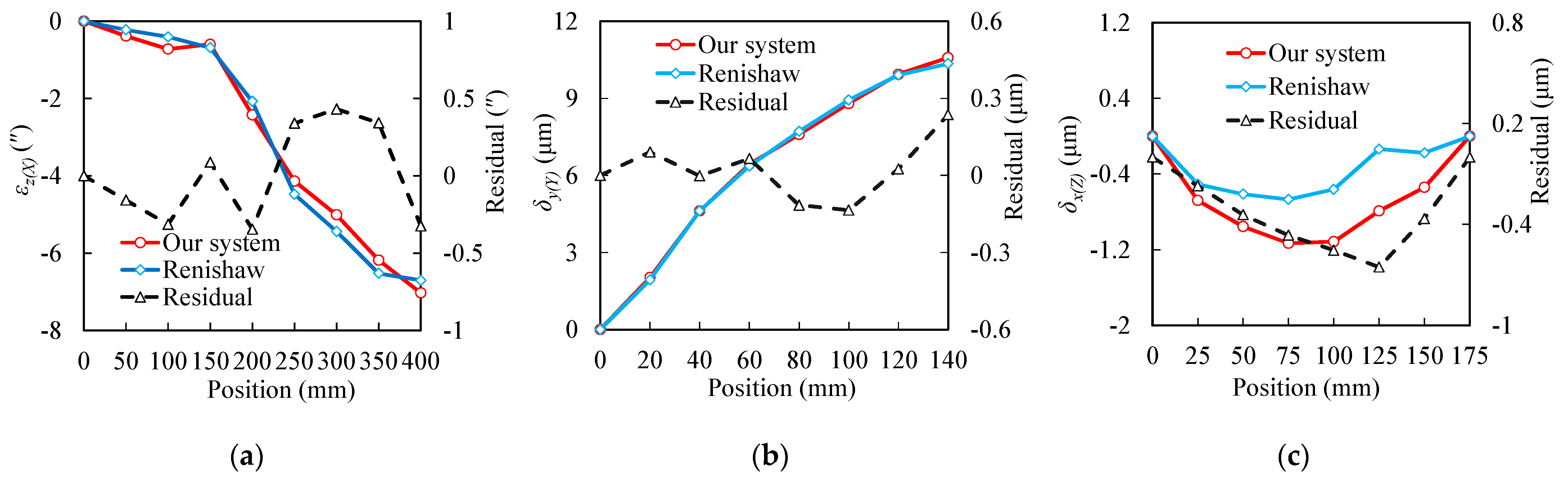
3.1. Measurement Experiments of 21 Geometric Errors

In order to verify the effectiveness of the above key error identification method, the 21 geometric errors of the vertical machine tool TH5656 are measured beforehand using our developed measurement system [21], as depicted in Figure 1. This system mainly consists of the laser source, the sensor head, the 18-error sensing target and beam-steering devcice. In the 18-error sensing target, three mutually perpendicular six-error sensing components have been assembled; each component is sensitive to the six geometric errors for the X-, Y-, and Z-axes, respectively. The beam-steering device features a pentaprism as its primary component. By introducing the pentaprism into the optical path and rotating it 90 degrees via a translation stage and a turntable, the measuring beams can be parallel to the Y- and Z-axes, respectively. Thus, this system allows simultaneous and precise measurement of the six-degree-of-freedom geometric errors of a linear guide. By precisely controlling the measuring beam to rotate 90° and utilizing a specially designed target, the 18 errors of the three linear axes can be directly sensed. Consequently, all 21 geometric errors are obtained through a one-step installation and a three-step automated measurement.
Before the measurement process, by adjusting the sensor head, the beam-steering device, and the 18-error sensing target, the beams along the X-, Y-, and Z-axes are all in the measuring range of the detectors. The installation and adjustment time is about 30 min. The measured distances are 400 mm, 140 mm, and 175 mm for the X-, Y-, and Z-axes of the TH5656, respectively, and the measurement intervals are 50 mm, 20 mm, and 25 mm, respectively. The measuring time for the three linear axes is about 5 min. The total time for measuring the TH5656 is about 35 min.
A Renishaw XL-80 laser interferometer is used for comparison. It is noted that the roll cannot be measured by the interferometer, and an electronic level (Qianshao WLII, accuracy 0.2 arcsec) is used for roll comparison, thus the roll of the vertical axis cannot be measured by the electric level. Since the different components need to be installed for each error measurement, the interferometer needs to be readjusted. The total time for measuring 20 errors of the TH5656 is about 680 min. Compared with the laser interferometer and electronic level, the measuring time of the developed system saves nearly 11 h and greatly improves measurement efficiency.
Table 2 shows the measurement results of the 21 geometric errors of the three linear axes of the TH5656 obtained by the developed system. These results refer to the difference between the maximum and minimum measurement values for each error component. Figure 2 shows the comparison results of three kinds of errors on different axes. The maximum comparison deviations are 0.43″, 0.24 μm, and 0.65 μm for yaw, position error, and straightness, respectively. It can be observed that the accuracy of the proposed system is equivalent to that of the interferometer. Furthermore, the laser interferometer has long measurement period, during which the measurement environment undergoes changes, leading to a decrease in comprehensive accuracy. In contrast, the proposed high-efficient measurement method not only significantly reduces the time required for machine tool measurements, but also ensures higher comprehensive measurement accuracy.

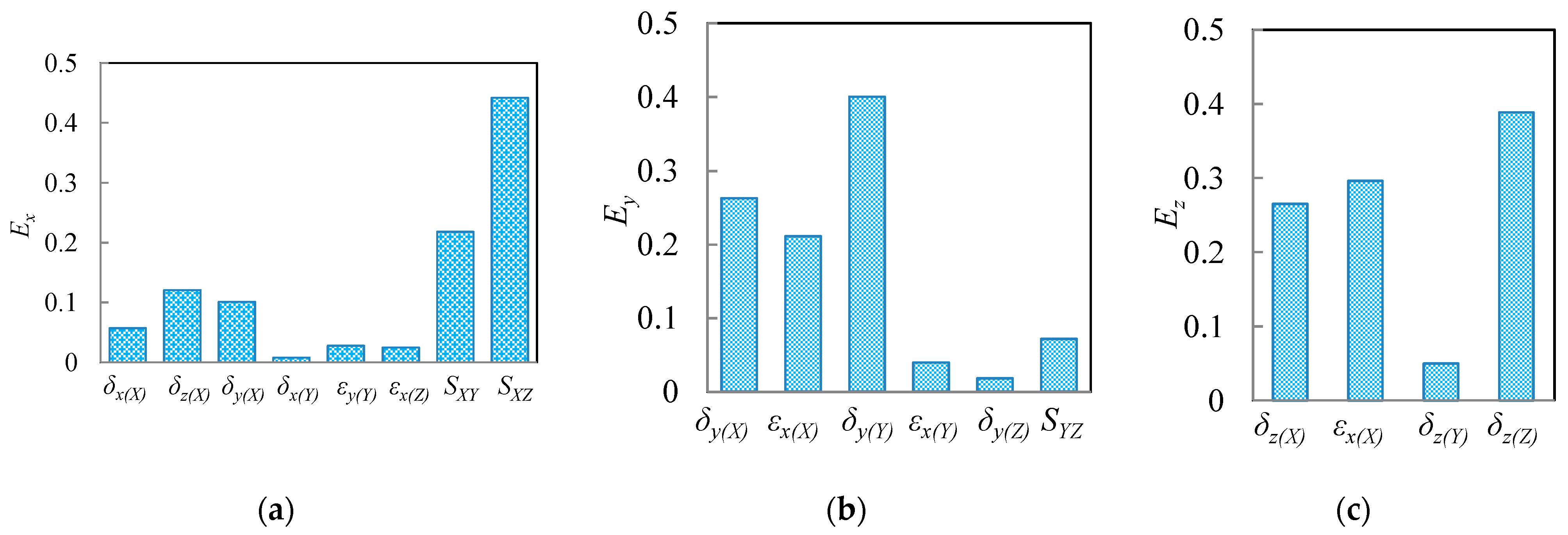
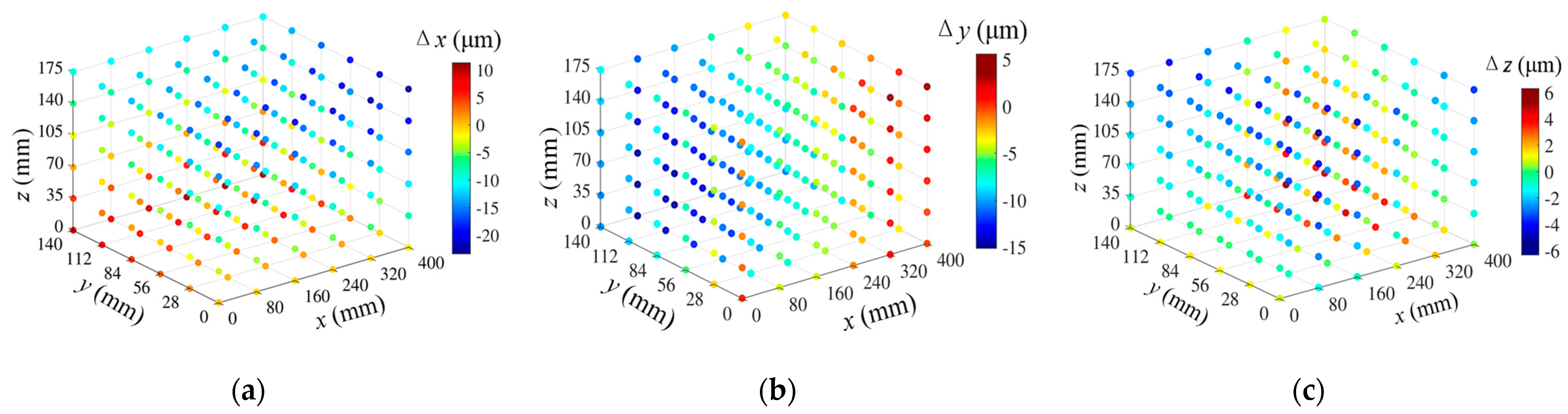
3.2. Sensitivity Analysis of 21 Geometric Errors

The geometric error measurement results can be expressed as polynomial functions related to the position coordinates of the machine tool. Considering the nonlinear distribution of the measurement results, a third-order polynomial was employed to fit the geometric error elements, with the exception of the squareness error which remained constant and did not require fitting. After fitting, the geometric errors were substituted into Equation (1) to obtain the volumetric errors of the TH5656, as depicted in Figure 3, wherein the intervals for the X-, Y-, and Z-axes were set to 80 mm, 28 mm, and 35 mm, respectively. A total of 216 points were selected, and different colors were utilized to represent the magnitude of the volumetric errors. It can be observed that the ranges of Δx, Δy, and Δz were −23.26μm to 11.27 μm, −15.12 μm to 3.56 μm, and −5.31 μm to 5.29 μm, respectively. Then, the distribution of the influence factors of each geometric error element on the volumetric errors of the TH5656 can be calculated by substituting the magnitude of the 21 geometric errors from Table 2 into Equation (5). The resulting distribution of impact factors is presented in Figure 4. It reveals that the volumetric error ∆x is primarily influenced by SXY and SXZ, with the sum of their impact factors being 0.66, as shown in Figure 4a. Similarly, the volumetric error ∆y is primarily affected by δy(X), εx(X), and δy(Y), with a cumulative impact factor of 0.87, as shown in Figure 4b. For the volumetric error ∆z, it is mainly influenced by δz(X), εx(X), and δz(Z), with a cumulative impact factor of 0.95, as shown in Figure 4c. These errors are the identified key error elements. Thus, we can prioritize the measurement and compensation of these errors to improve error compensation efficiency and ultimately improve the machining accuracy.

4. Conclusions

This paper presents an efficient method for identifying key errors based on the previously proposed a 21-geometric-error measurement method and system of the three linear axes of machine tools. Additionally, a sensitivity analysis model for the 21 geometric errors is built using the global sensitivity analysis method to obtain the contribution of each error to the volumetric errors of machine tools. The experiments on the vertical CNC machine tool TH5656 reveal that all 21 geometric errors are obtained within 5 min. Finally, the key error factors affecting the manufacturing and machining accuracy of the TH5656 are identified. This new method offers valuable guidance for machine tool configuration design, machining process determination, and geometric error compensation.

Author Contributions

Conceptualization, F.Z. and Q.F.; methodology, F.Z. and B.Z.; software, F.Z.; validation, Y.Z. and J.L.; formal analysis, Y.Z.; investigation, B.Z.; resources, Q.F.; data curation, F.L.; writing—original draft preparation, F.Z.; writing—review and editing, F.Z.; visualization, F.L.; supervision, J.L.; project administration, Q.F.; funding acquisition, Q.F. All authors have read and agreed to the published version of the manuscript.

Funding

This research was funded by the Science and Technology Innovation Project of Xiong’an New Area of China, grant number 2022XAGG0200, and the National Natural Science Foundation of the China-Major Program, grant number 51527806.

Institutional Review Board Statement

Not applicable.

Informed Consent Statement

Not applicable.

Data Availability Statement

The original contributions presented in the study are included in the article, further inquiries can be directed to the corresponding author.

Conflicts of Interest

The authors declare no conflicts of interest.

References

  1. Hong, C.; Ibaraki, S.; Matsubara, A. Influence of position-dependent geometric errors of rotary axes on a machining test of cone frustum by five-axis machine tools. Precis. Eng. 2011, 35, 1–11. [Google Scholar] [CrossRef]
  2. Khan, A.W.; Chen, W. A methodology for systematic geometric error compensation in five-axis machine tools. Int. J. Adv. Manuf. Technol. 2011, 53, 615–628. [Google Scholar] [CrossRef]
  3. Zhu, S.; Ding, G.; Qin, S.; Jiang, L.; Zhuang, L.; Yan, K. Integrated geometric error modeling, identification and compensation of CNC machine tools. Int. J. Adv. Manuf. Technol. 2012, 52, 24–29. [Google Scholar] [CrossRef]
  4. Gao, W.; Ibaraki, S.; Donmez, M.A.; Kono, D.; Mayer, J.R.R.; Chen, Y.L.; Szipka, K.; Archenti, A.; Linares, J.M.; Suzuki, N. Machine tool calibration: Measurement, modeling, and compensation of machine tool errors. Int. J. Mach. Tools Manuf. 2023, 187, 104017. [Google Scholar] [CrossRef]
  5. Ramesh, R.; Mannan, M.A.; Poo, A.N. Error compensation in machine tools—A review Part I: Geometric, cutting-force induced and fixture-dependent errors. Int. J. Mach. Tools Manuf. 2000, 9, 1235–1256. [Google Scholar] [CrossRef]
  6. Li, H.; Zhang, P.; Deng, M.; Xiang, S.; Du, Z.; Yang, J. Volumetric error measurement and compensation of three-axis machine tools based on laser bidirectional sequential step diagonal measuring method. Meas. Sci. Technol. 2020, 31, 055201. [Google Scholar] [CrossRef]
  7. Lee, K.I.; Yang, S.H. Accuracy evaluation of machine tools by modeling spherical deviation based on double ball-bar measurements. Int. J. Mach. Tools Manuf. 2013, 75, 46–54. [Google Scholar] [CrossRef]
  8. Slamani, M.; Mayer, R.; Balazinski, M. Concept for the integration of geometric and servo dynamic errors for predicting volumetric errors in five-axis high-speed machine tools: An application on a XYC three-axis motion trajectory using programmed end point constraint measurements. Int. J. Adv. Manuf. Technol. 2012, 65, 1669–1679. [Google Scholar] [CrossRef]
  9. Bringmann, B.; Küng, A.; Knapp, W. A measuring artefact for true 3D machine testing and calibration. CIRP Ann. 2005, 54, 471–474. [Google Scholar] [CrossRef]
  10. Chen, H.; Jiang, B.; Shi, Z.; Sun, Y.; Song, H.; Tang, L. Uncertainty modeling of the spatial coordinate error correction system of the CMM based on laser tracer multi-station measurement. Meas. Sci. Technol. 2019, 2, 025007. [Google Scholar] [CrossRef]
  11. Lee, C.; Kim, G.H.; Lee, S.K. Design and construction of a single unit multi-function optical encoder for a six-degree-of-freedom motion error measurement in an ultraprecision linear stage. Meas. Sci. Technol. 2011, 22, 105901. [Google Scholar] [CrossRef]
  12. Cai, Y.; Wang, L.; Liu, Y.; Li, C.; Fan, K.C. Accuracy improvement of linear stages using on-machine geometric error measurement system and error transformation model. Opt. Express 2022, 30, 7539–7550. [Google Scholar] [CrossRef] [PubMed]
  13. Liu, W.; Yu, Z.; Duan, F.; Hu, H.; Fu, X.; Bao, R. Robust five-degree-of-freedom measurement system with self-compensation and air turbulence protection. Opt. Express 2023, 31, 4652–4666. [Google Scholar] [CrossRef] [PubMed]
  14. Yu, K.; Zhu, J.; Yuan, W.; Zhou, Q.; Xue, G.; Wu, G.; Wang, X.; Li, X. Two-channel six degrees of freedom grating-encoder for precision-positioning of sub-components in synthetic-aperture optics. Opt. Express 2021, 29, 21113–21128. [Google Scholar] [CrossRef] [PubMed]
  15. Zhou, S.; Le, V.; Xiong, S.; Yang, Y.; Ni, K.; Zhou, Q.; Wu, G. Dual-comb spectroscopy resolved three-degree-of-freedom sensing. Photonics Res. 2021, 9, 243–251. [Google Scholar] [CrossRef]
  16. Li, D.; Feng, P.; Zhang, J.; Yu, D.; Wu, Z. An identification method for key geometric errors of machine tool based on matrix differential and experimental test. Proc. Inst. Mech. Eng. C J. Mech. Eng. Sci. 2014, 228, 3141–3155. [Google Scholar] [CrossRef]
  17. Cheng, G.; Ge, S.R. Error model and analysis of 3-RPS symmetrical parallel robot leg with three degree-of-freedom. J. China Univ. Min. Technol. 2009, 38, 50–55. [Google Scholar]
  18. Yang, Y.; Zhu, M.; Li, H.; Du, Z.; Yang, J. Volumetric error modelling and compensation for batch of vertical machining centers based on sensitivity analysis. J. Mech. Eng. 2020, 56, 204–212. [Google Scholar]
  19. Cui, C.; Feng, Q.; Zhang, B.; Zhao, Y. System for simultaneously measuring 6DOF geometric motion errors using a polarization maintaining fiber-coupled dual-frequency laser. Opt. Express 2016, 24, 6735–6748. [Google Scholar] [CrossRef] [PubMed]
  20. Zheng, F.; Feng, Q.; Zhang, B.; Li, J. A method for simultaneously measuring 6DOF geometric motion errors of linear and rotary axes using lasers. Sensors 2019, 19, 1764. [Google Scholar] [CrossRef] [PubMed]
  21. Zheng, F.; Feng, Q.; Zhang, B.; Li, J.; Zhao, Y. A high-precision laser method for directly and quickly measuring 21 geometric motion errors of three linear axes of computer numerical control machine tools. Int. J. Adv. Manuf. Technol. 2020, 109, 1285–1296. [Google Scholar] [CrossRef]
  22. Du, Z.; Fan, K.; Yang, J. Technique and Application in Error Compensation for CNC Machine Tools, 1st ed.; China Machine Press: Being, China, 2020; pp. 63–65. [Google Scholar]
Figure 1. Measurement of 21 geometric errors for the vertical machine tool: (a) developed measurement system; (b) vertical machine tool TH5656; and (ce) measurement of six errors of the X-, Y-, and Z-axes, respectively.
Applsci 14 02982 g001
Figure 2. Comparison results: (a) yaw of X-axis; (b) position error of Y-axis; and (c) straightness of Z-axis.
Applsci 14 02982 g002
Figure 3. Volumetric error distribution of TH5656: (a) volumetric error Δx in X-direction; (b) volumetric error Δy in Y-direction; (c) volumetric error Δz in Z-direction.
Applsci 14 02982 g003
Figure 4. Influence factor distribution of TH5656: (a) influence factor Ex in X-direction; (b) influence factor Ey in Y-direction; (c) influence factor Ez in Z-direction.
Applsci 14 02982 g004
Table 1. 21 geometric errors for the three linear axes of machine tools.
Geometric ErrorsX-AxisY-AxisZ-Axis
Position errorδx(X)δy(Y)δz(Z)
Horizontal straightnessδy(X)δx(Y)δy(Z)
Vertical straightnessδz(X)δz(Y)δx(Z)
Yawεz(X)εz(Y)εx(Z)
Pitchεy(X)εx(Y)εy(Z)
Rollεx(X)εy(Y)εz(Z)
Squareness errorSXY, SZX, SYZ
Table 2. Measurement results of 21 geometric errors.
Translational Error (μm)Angular Error (″)
X-Axisδx(X)δy(X)δz(X)εz(X)εy(X)εx(X)
2.576.943.497.034.726.24
Y-Axisδx(Y)δy(Y)δz(Y)εz(Y)εy(Y)εx(Y)
0.3510.590.661.861.311.15
Z-Axisδx(Z)δy(Z)δz(Z)εz(Z)εy(Z)εx(Z)
1.130.465.121.530.471.42
Squareness errorSXY: 20.59″; SYZ: 12.71″; SZX: 2.11″
Disclaimer/Publisher’s Note: The statements, opinions and data contained in all publications are solely those of the individual author(s) and contributor(s) and not of MDPI and/or the editor(s). MDPI and/or the editor(s) disclaim responsibility for any injury to people or property resulting from any ideas, methods, instructions or products referred to in the content.

