1. Motivation
The authors’ scientific research aim is to develop numerical and experimental methods to design a surgical robot with a remote center of motion (RCM) mechanism that is free of mechanical vibrations and has the necessary strength stability for soft tissue surgery. A key consideration is the robot’s functionality, which refers to its ability to operate on cardiovascular tissue in a manner acceptable to cardiac surgeons, including performing procedures, like coronary aortic anastomosis, that are difficult to perform with classical techniques. For soft tissue surgery, the robot must also ensure the required speed of tools, the smoothness of their movement, positioning accuracy, and repeatability, which are crucial for the robot’s usefulness in the minimally invasive robotic surgery technique (MIRS) [
1,
2,
3]. Achieving positive results on these technical issues would enable the submission of a surgical robot prototype for animal testing and eventually human testing.
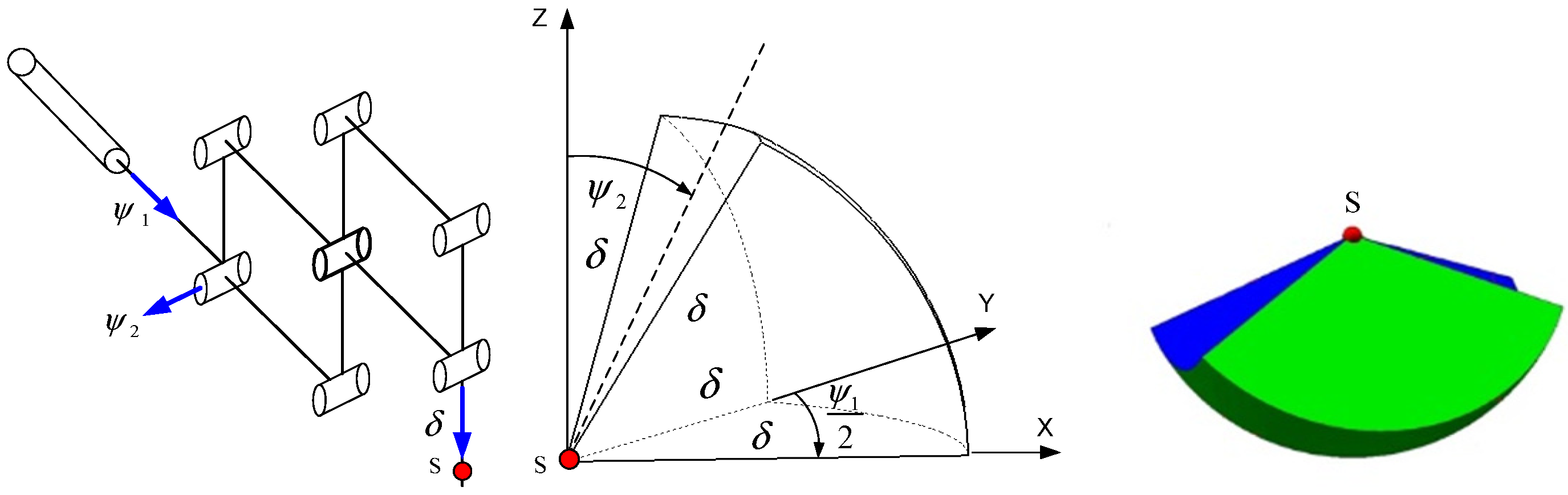
Currently, teleoperators (controller–responder structures) are used for soft tissue surgery. The surgeon’s movement instructions are transmitted through the controller and converted into the movement of the responder, an endoscopic surgical instrument in direct contact with the cardiovascular tissue, after making small incisions in the chest. In this study, the authors analyzed the structure of a surgical robot with a RCM that moves in a spherical manner after the endoscopic tool passes through the surgical port, or trocar, which is placed in the outer shells of the human body during (MIRS) surgery. The authors’ goal is to determine the optimization model, taking into account relevant physical criteria and specifying the constraints for decision variables. The decision variables are defined as geometric dimensions of abstracted links because they affect the criteria adopted. The discussed mechanical system can be observed in the clinically used da Vinci or Robin Heart surgical robots, which allows the operation to be performed in a minimally invasive manner. This structure is not based on the open kinematic chain found in the mechanisms of industrial robots. It consists of rigid links connected in joints forming parallel systems, enabling the retrieval of constant point kinematics. The structure is illustrated in
Figure 1, together with the resulting shape of the working space. The authors validated the correctness of Formula (1) using a computer aid design (CAD) model.
Due to the spherical shape of the working space, as shown in
Figure 1, it is convenient to describe it using a triple integral in spherical coordinates, which allows for the calculation of the volume of the working space using Formula (1). The integral depends on the connector variables of the RCM mechanism:
.
where
—RCM link variables.
Before manufacturing the prototype of the surgical robot with the mechanism (RCM) shown in
Figure 1, it is necessary to determine the optimal values for the relevant strength criteria (such as natural frequency, buckling coefficient, static and dynamic safety coefficient, and effector displacement) using an established method with a known mathematical basis that applies to the mechanical structure, assuming that forces and displacements maintain physical relationships for the selected construction material. In this study, we consider the finite element method to be such a method, which allows us to obtain results for the structure of a surgical robot with a complex shape and load state in the field of stresses and displacements, and the non-dominated sorting genetic algorithm (NSGA-II) based on non-dominated Pareto solutions that are insensitive to local minima of the optimized vector function. The (NSGA-II) algorithm is one of the most efficient algorithms for calculating the optimum for vector functions [
4]. Of course, this requires the formulation of a theoretical model. The idea is simple: for a known field of displacements in the mesh model, we calculate the strains from geometric relationships and then calculate the stresses based on constitutive equations. We then formulate a metamodel using the Kriging method, which expresses the dependence of criteria on decision variables based on finite element method (FEM) numerical experiments [
5].
Using the (NSGA-II) algorithm to calculate the optimum results in an increase in the safety of use and improved dynamics of the mechanical system of the surgical robot, which leads to improved positioning accuracy, repeatability, and durability. For example, due to the optimal rigidity of the surgical robot system, it will not loosen and permanently deform. The scientific problem considered in many scientific works on robotics, such as [
6,
7,
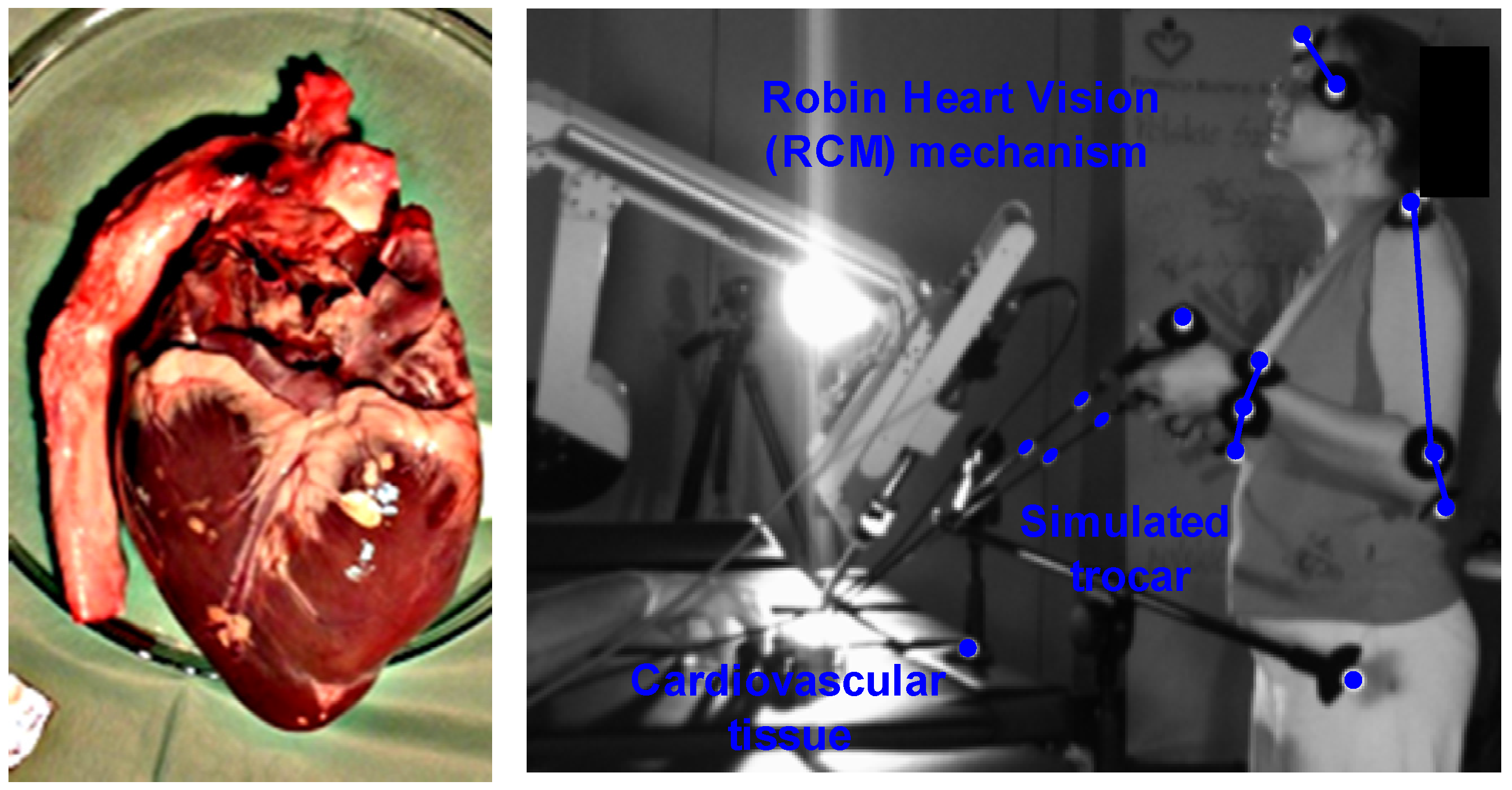
8], is reformulated by adding equations describing the magnitude of inputs resulting from two in vitro experiments on cardiovascular tissue to the system. Kinematic inputs from the experiment were obtained during surgical procedures on cardiovascular tissue performed by an experienced cardiac surgeon using endoscopic instruments, cardiovascular tissue on a professional operating table, and a station simulating trocars in the patient’s body. The experiment was conducted using the Robin Heart Vision surgical robot, and trajectory signals were acquired using four complementary metal–oxide–semiconductor (CMOS) sensors. The use of acceptable perturbations from a mechanical point of view (e.g., no jerks in the mechanical system or tearing of tissue caused by the endoscopic tool) and from the opinion of a medical expert (an experienced surgeon) ensures the kinematic functionality that adjusts kinematic parameters, such as speed, enabling the assessment of real states that appear in the structure of the surgical robot. The second in vitro experiment aimed to determine the magnitude of force inputs that appear at the tip of a surgical scalpel, puncture needle, and intender, enabling the assessment of tissue stiffness, useful in haptic feedback techniques using an electronic dynamometer. The obtained values with a normal distribution according to the Kolmogorov–Smirnov statistical test were used as inputs for the strength model calculated using the (FEM) technique. Both experiments were performed in vitro on cardiovascular tissue (Sus Scrofa f. domestica).
2. Literature Review
The paper presents a concept of searching for optimal values taking into account the inputs from in vitro experiments on cardiovascular tissue, which is related to a large number of important scientific approaches. In [
9], the authors deal with the optimization of the dimensions of the links of a medical robot for surgery using a genetic algorithm and a gradient method. They give the dimensions of the three working spaces necessary for minimally invasive surgery (MIS) and state the need to obtain data on the velocities during minimally invasive operations. In this paper, such an experiment is performed using four sensors (CMOS), and the need to calculate the volume of working spaces for other areas of the body is also highlighted.
In [
10], the Vicon optical system was used to obtain the kinematic values of a medical robot with a controller–responder structure, and a genetic algorithm was used for optimization aimed at obtaining the required volume of working space. It was found that it is possible to obtain the kinematic values of a surgical robot using other methods, such as systems inertial measurement unit (IMU) and optic test station (OTS), as illustrated in works [
11,
12,
13] with the advantages and disadvantages of their use. In [
14], the use of the IMU sensor to measure displacements of the construction of a medical robot, useful during COVID-19 for contact with infected patients, is described.
In [
15,
16], a vector function was formulated with criteria such as workspace size, kinematic performance, and index of compactness of the manipulator to obtain the correct result for the structure of two spherical wrists (serial and parallel) for applications in medical robotics (tele-echography). The authors state that a medical robot must be handy to be approved by a doctor for surgery, despite meeting the mathematical requirements. This approach was used in this study, where the final assessment of the MIS technique’s suitability was made by an experienced cardiac surgeon.
Details of the optimization method based on the non-dominated sorting genetic algorithm (NSGA-II) are provided in [
17]. In [
18], the NSGA-II algorithm was utilized to optimize a surgical robot with a remote center of motion (RCM) mechanism. Pareto fronts were also employed in this formulation. The work [
19] presents a tabular classification of multi-criteria genetic algorithms, along with their advantages and disadvantages. In [
20], the Kriging method was applied to create a metamodel used in computer-aided strength calculations, which was compared to the polynomial approximation method of the response surface obtained from discrete data. The fundamental work in the field of the discussed method is [
21]. The application of the finite element method to the construction of the da Vinci surgical robot was demonstrated in [
22], which analyzed the phenomenon of resonance, including the eigenfrequencies and shapes of resonant vibrations. The work does not provide an important parameter, which is the safety factor obtained by the FEM method for the da Vinci robot. However, it presents an interesting way of writing the eigenvibration equation based on Lame coefficients. The strength model presented in this paper is a much more complex model, which more accurately reflects the prevailing physical phenomena. In [
23], deformations of the surgical robot were determined in the robot-assisted minimally invasive surgery (RMIS) technique using the finite element method. Displacements can also be significant results from the perspective of the positioning accuracy of the effector.
In both papers discussed, the integrals of differential equations are calculated using the Runge–Kutta method with the Bogacki–Samfine and Dormand–Prince variants [
24,
25]. They provide the mathematical foundations of ordinary differential equations solvers (ODE3) and (ODE45) used to solve dynamics models in the Matlab 2023 software. Methods of solving the equation of dynamics of transient states by the Newmark method should be found in [
26]. The method of solving the buckling problem using the Lanchos method is described in [
27]. The work [
28] shows the use of a proportional–integral–derivative controller (PID) for the construction of a two-unit medical robot. The Euler–Lagrange approach was used to describe the dynamics of the manipulator. The dynamics model was created in the Matlab/Simulink environment. To formulate the dynamics model in this work, the block diagram method was used [
29]. The model was built similarly to the described work in the Matlab/Simulink environment. In the work [
30], the Matlab/Simulink environment was used to design a control model for a laparoscopic medical manipulator based on a controller (PID). The paper describes methods of controlling laparoscopic manipulators. The authors claim that (PID) controllers are still suitable for controlling medical manipulators due to the simplicity and explicit tuning procedures. However, they offer a more modern feed-forward control method. In paper [
31], the authors propose a control based on a controller (PID) and compare it with a control (PID) based on a neural network. Numerical experiments were carried out in the Matlab/simulink environment. The work [
32] describes the control of a surgical robot using a fuzzy controller (PID). The interactive fuzzy controller (PID) was used in [
33]. Work [
34] shows the control (PID) of a surgical robot with a mechanism (RCM).
The LuGre model of friction, which takes into account the deformability of mating surfaces in joints and the Stribeck effect, is described in detail in [
35,
36,
37]. Other modern models of friction such as generalized Maxwell-slip (GMS) and Dahl are also described in [
38,
39].
The Robin Heart Vision surgical robot used in the in vitro experiment was described in [
40]. This robot was also subjected to operational tests on animals, as described in [
41]. The research conducted on the Robin Heart Vision surgical robot in these articles confirms its usefulness in rationalizing and innovating experiments in MIRS. Various mechanical systems that implement spherical kinematics, referred to as mechanisms (RCM), are illustrated in [
42,
43,
44], providing a basis for the search for new configurations of mechanisms (RCM). Such mechanisms can be characterized by greater rigidity, which translates into better positioning accuracy, easily controllable dynamics, and better functionality, as evaluated by medical experts. The basics of the algorithm (DLT) necessary to obtain trajectory data as a function of time for endoscopic tools are described in [
45,
46], which provide the foundation for creating software to determine the trajectories of real objects. Works on the use of optical systems to determine the kinematic parameters of endoscopic tools are illustrated in [
47,
48,
49]. On the other hand, experiments on determining the values of forces that appear at the ends of surgical instruments are described in works [
50,
51,
52]. The main conclusions reached indicate that reliable values of forces on soft tissues are in the range of 1 to 10 [N].
Based on the literature review, a research gap has been identified regarding the need to determine the kinematic parameters of minimally invasive tools. In this paper, the authors conducted an in vitro experiment on cardiovascular tissue using four sensors (CMOS) and the Robin Heart Vision surgical robot in the Biocybernetics Laboratory of the Foundation for the Development of Cardiac Surgery, Prof. Zbigniew Religa. A medical expert, an experienced cardiac surgeon, provided a positive assessment of the kinematic functionality of the experiment, specifically the speed and spurt parameters. The latter enables the evaluation of the tearing of the incised tissue during the procedure (MIS). Additionally, force measurements were taken at the tip of the scalpel, puncture needle, and bullet using an electronic dynamometer, which provided a basis for analyzing the haptic system feedback with one degree of freedom as an effector of a surgical robot with a mechanism (RCM). This novelty in this design allows a surgeon in one location to assess the stiffness of heart arteries from another location.
The determined force and kinematic data are incorporated into the surgical robot’s dynamic model. Using the finite element method and the genetic algorithm NSGA-II, the optimal structural design of a surgical robot for soft tissue surgery is obtained based on important mechanical criteria such as stability, resonance, and deformability while considering the influence of inertia. This represents the main result of the article. It should be noted that the developed structural model is more complex than those found in the cited literature. It includes a control and drive system based on a direct current (DC) motor and a sophisticated LuGre friction model that accounts for surface deformability and the Stri-beck effect. Additionally, it is interesting to consider the issue of statics alongside the dynamics of transient states, which takes into account the mechanical requirements of the robot in static positions while obtaining the required safety factor based on the robot’s structural flexibility during motion.
3. Materials and Methods
This paragraph describes the theoretical basis and presents the scientific methods and calculation tools used. It also provides a description of two in vitro experiments carried out on cardiovascular tissue using minimally invasive techniques. The first experiment aimed to determine the speed of endoscopic tools, which were then used as inputs for the optimization model of the surgical robot. This experiment was conducted by an experienced cardiac surgeon using the Robin Heart Vision robotic surgical mechanism (RCM) in the MIRS technique. The second experiment aimed to determine the force inputs to the discussed model using an electronic dynamometer. Both experiments were performed in vitro on cardiovascular tissue. The block diagrams method used in this work transformed equations describing various physical phenomena appearing in the structure of the surgical robot into block diagrams that enable the interactive simulation of the model. As a result, a model of a (DC) motor, an optimal controller (PID), and a modern LuGre model of friction were created. This paragraph also formulates a computational multi-criteria optimization model solved using the (NSGA-II) algorithm, with decision variables defined for it and important criteria related to physical phenomena that appear in the structure of a surgical robot with a mechanism (RCM) based on observations of the work of medical robots Robin Heart 1, Robin Heart 2, and Robin Heart Vision. Restrictions were also imposed on decision variables.
3.1. In Vitro Experiment of Obtaining Kinematic Values for the Dynamics Model of a Surgical Robot with the RCM Mechanism
The experimental study aimed to obtain speed data for the mathematical optimization model of a surgical robot and was conducted at the Biocybernetics Laboratory of the Cardiac Surgery Foundation under the supervision of Prof. Zbigniew Religa. The experimental setup was designed by experts in mechatronics, biomechanics, and medicine and included a professional operating table, tripods with hollow ball joints simulating access trocars, cardiovascular tissue (Sus. Scrofa f. domestica), a surgical robot Robin Heart Vision with an endoscopic camera, and two endoscopic tools for soft tissue manipulation. The tissue used in the experiments was purchased in a regular store. An experienced cardiothoracic surgeon conducted the experiment, and their opinion as a medical expert was crucial in assessing the performed medical procedures. The study focused on endoscopic tools interacting with cardiovascular tissue. The surgeon observed the operating field on a panel, which displayed the image received from the endoscopic camera of the Robin Heart Vision surgical robot. Reflective markers were attached to each endoscopic tool to obtain their trajectories in relation to the absolute system.
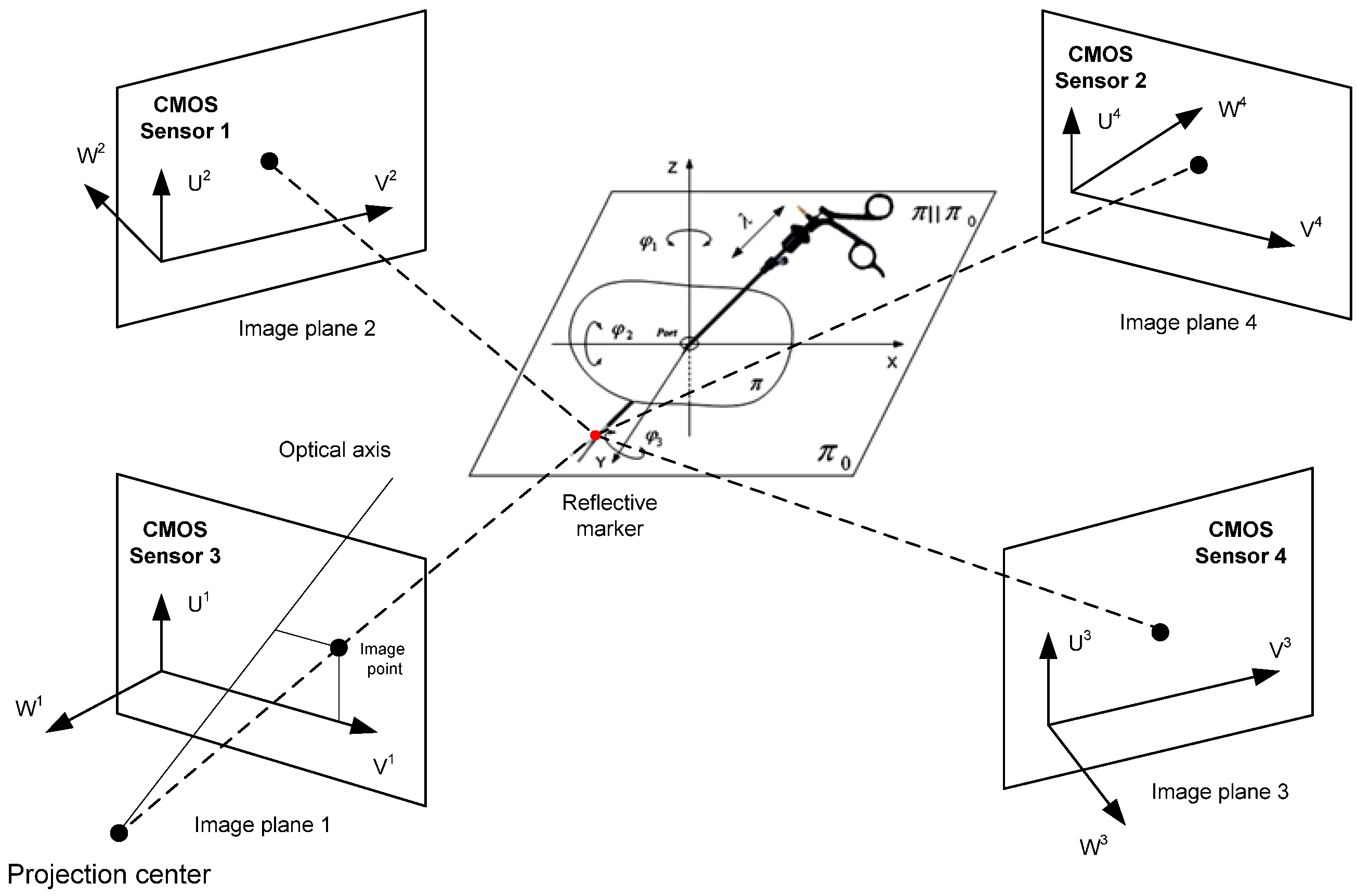
The experimental setup utilized a system of four Basler A602fc-2 (CMOS) sensors (Basler, Ahrensburg, Germany). The sampling frequency of the reflective marker trajectory signal was 100 [Hz]. The measurement accuracy obtained was equal to ∓2 [mm] relative to the assumed reference in the form of a rigid sleeve with two reflective markers. Gaps in the trajectory resulting from the obstruction of the reflective marker by the upper limbs of the cardiothoracic surgeon were approximated in the flat sections along the X, Y, and Z axes using Lagrange interpolation. The random component of the trajectory signal was removed using the Savitzky–Golay polynomial smoothing method. The method parameters were optimally selected using the Durbin–Watson statistical test. The formula for calculating the optimal width of the interval defining the “measurement window” is formulated as
where
—discrete i trajectory data;
—discrete data, i″ after smoothing;
—number of discrete trajectory data.
The problem of calculating the trajectory was carried out using the direct linear transformation (DLT) algorithm. The matrix defining the absolute coordinates of the reflective marker has the form
where L
1…L
11 are the optical sensor parameters generated by applying the (APAS) system.
In order to be able to reproduce the experiment, a matrix was provided that can be used to calculate the positions of the (CMOS) sensors in relation to the reflective marker attached to the endoscopic tool:
where X, Y, and Z are cartesian coordinates of the marker, and U and V are coordinates of the optical sensor. The table below shows the two velocity values obtained for the setting and positioning movements of the instrument relative to the heart tissue.
The use of optical sensors in the experiment allows for the evaluation of the obtained experimental results while simultaneously observing the sequence of movements of the biokinematic chain and endoscopic tools as well as the robot by a medical expert on the visual panel.
3.2. Experiment In Vitro to Obtain Force Values for the Dynamics Model
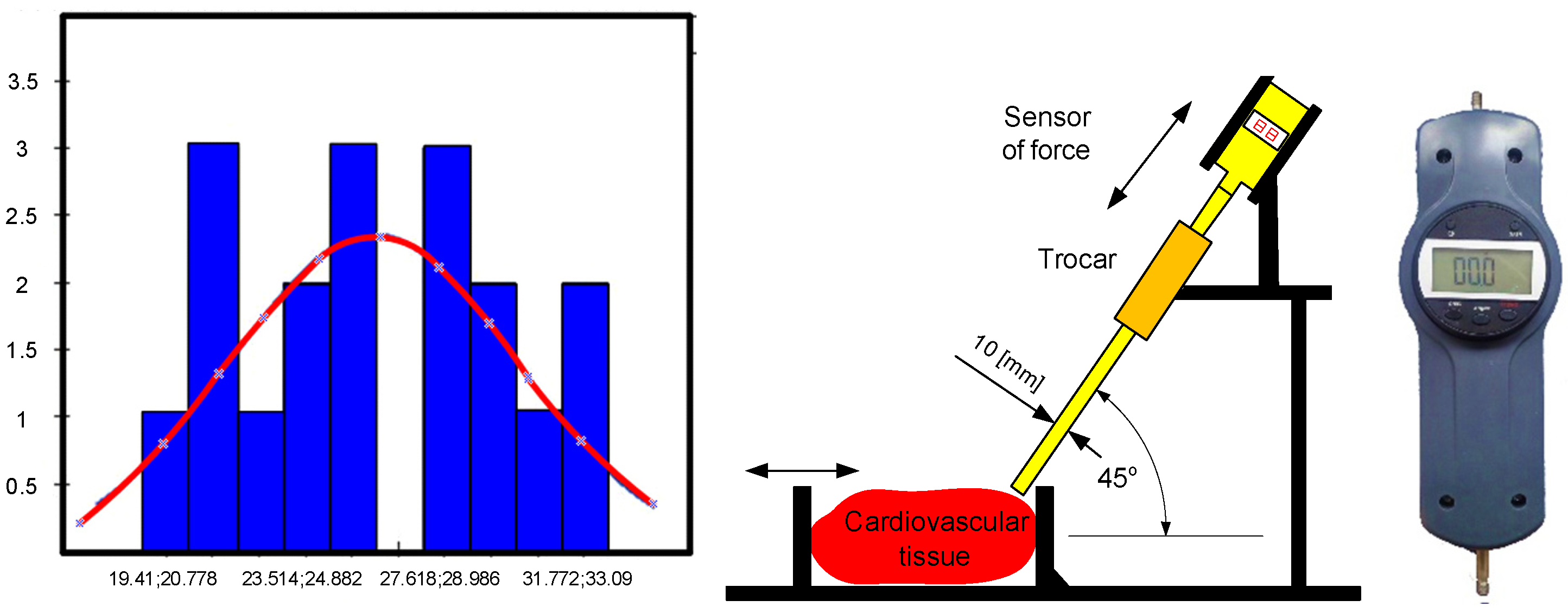
Tests were conducted using a force sensor to determine the force values required for the effector of a surgical robot with the RCM mechanism to assess tissue stiffness, detect the beginnings of a tumor or artery pulsation, make an incision with a scalpel, and puncture with a puncture needle. The forces that prevail at the end of the bullet in the form of a sleeve were particularly important to determine as they can be used to test the stiffness of heart tissue in the MIRS technique. These results form the basis for analyzing the haptic feedback problem, which can be easily applied to the technological application of a system with one degree of freedom. Insertions into the heart tissue were made using a scalpel and a puncture needle, and multiple insertions of the scalpel from different angles did not result in a value greater than 3.09 [N]. A cut was also made with a scalpel inserted at a distance of 1.5 [cm]. The results of the repeated 36 insertions of the bullet at a distance of 0.5 [cm] into the wall of the left ventricle yielded a normal distribution, which was confirmed by the Kolmogorov–Smirnov statistical test at a significance level of 0.05. The following distribution parameters were obtained: arithmetic mean = 24.29, standard deviation = 3.91, D-statistic = 0.14, degrees of freedom = 36, and
p-value = 0.49. The experiment using CMOS sensors is illustrated in the
Figure 2 and
Figure 3.
Figure 4 shows the experimental setup for puncturing the left heart wall, along with the histogram and normal distribution curve obtained.
3.3. Statical Strength Problem
The issue of structural statics applied to the RCM mechanism is described by the expression
where
The stiffness matrix is defined as
where
The vector of nodal displacements is defined as
Displacement in any point of the element is defined as
where
The field of displacements is defined as
where
The components of the displacement tensor inside an element have the form
where
The strength calculations are based on the von Mises energy hypothesis given in the physical interpretation of Henecky’s formula:
where
Using shear and normal stresses, the reduced stress according to von Mises’ energy hypothesis has the form
where
—the tensile stress;
—the shear stress.
The static model in this article is solved using the Newton–Raphson method [
22].
3.4. The Phenomenon of Elastic Buckling
The term related to determining eigenvectors and eigenvalues in mechanical problems of frequencies is related to the geometric matrix determined by the condition (15).
The stress–stiffness matrix is determined by
where
On this basis, and taking into account Equation (5), we obtain the eigenvalue problem of elastic buckling in matrix form:
It is stated simultaneously that while losing stability, other states of equilibrium are possible.
After subtracting the equations, the symmetrical problem that defines the stability of the substitution system is obtained to solve
where
—eigenvalues, which are load coefficients, and
—eigenvector, which is the shape of buckling. This phenomenon is solved via the Lanchos method.
3.5. The Phenomenon of Natural Vibrations
The linear buckling phenomenon is related to the solution of the equation in matrix form:
The mass matrix can be written as
where
—density, and [N]—matrix of shape function.
The general solution of Equation (8) has a following form:
After substituting (11) to (8), the equation called eigenequation was obtained:
where
—eigenvalues, which are natural frequencies of the effector;
—eigenvectors, that are mode shapes of the effector.
The natural frequency problem is solved via the von Mises iteration method.
3.6. Phenomena of Damping, Inertia, and Stiffness during Transient Dynamics Analysis
Equation (24) is a second-order linear differential matrix equation with constant coefficients and non-homogeneous terms. This equation describes the complete dynamics model, taking into account deformations from previous iterations that affect deformations in subsequent time steps of the finite element method calculations.
where
The unsteady state model, i.e., Equation (24), is solved using the Newmark method.
3.7. Model of Dynamics of Drive Torques
The model of the dynamics of torque was created using the block diagram method in the Matlab/Simulink environment. The model’s mass characteristics, inertia matrices, and center of gravity positions were determined. The model was formulated for aluminum material. A PID control and a DC actuator were added to the model. The model also included a modern LuGre friction model. The model was supplemented with force and velocity inputs obtained during in vitro experiments on cardiovascular tissue. The model of dynamics of driving torques of the surgical robot is illustrated in the
Figure 5.
The dynamics model was solved using the Runge–Kutta method in the Dormand–Prince variant in the Simulink environment using the (ODE45) solver.
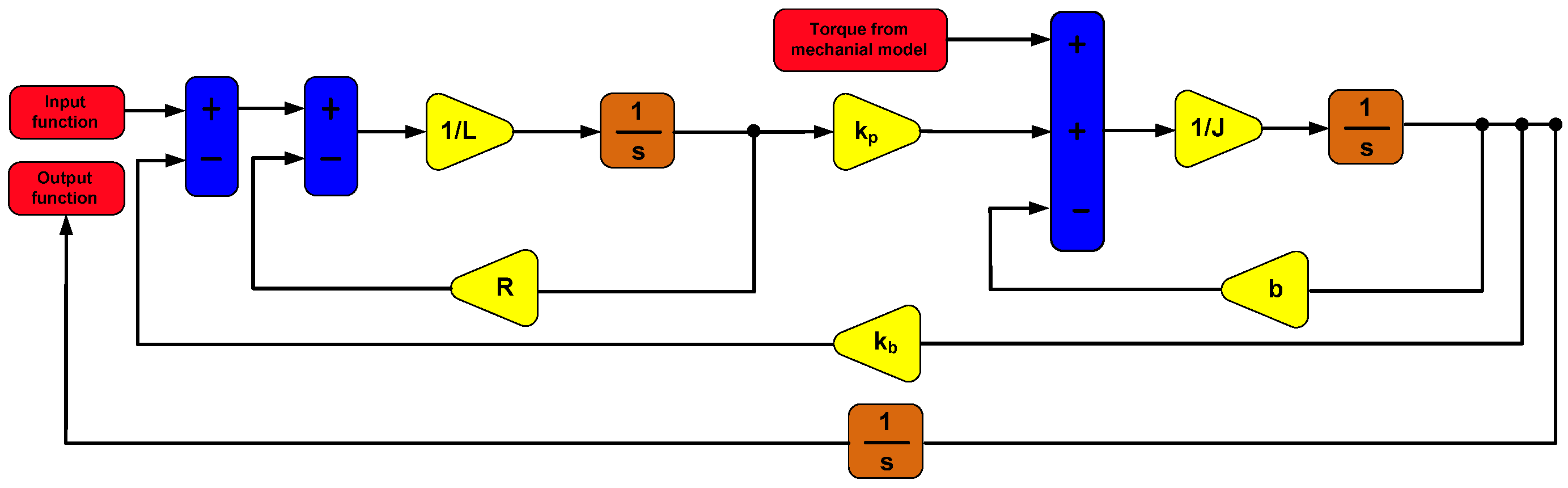
3.8. DC Motor Model
The model of a DC motor generating rotary motion in the joints of the RCM mechanism of a surgical robot is described by the following equations:
where
DC motors are commonly used drives for the joints of surgical robots and their effectors. The block diagram to which Equations (25) and (26) were transformed is illustrated in
Figure 6.
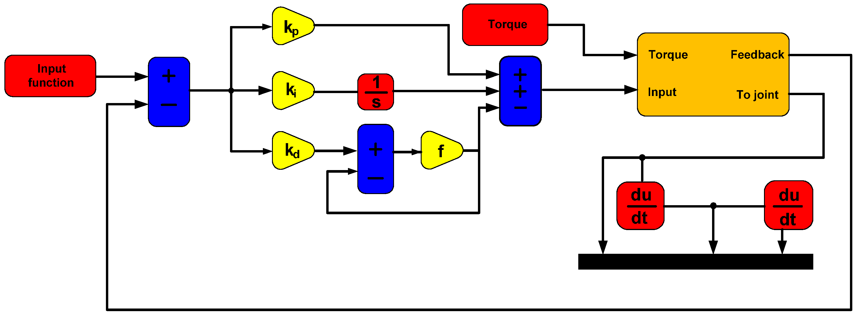
3.9. PID Controller Model
The surgical robot with the RCM mechanism was controlled using position control based on a PID controller. This control is characterized by a lack of connection between the control systems of successive joints of the surgical robot. The PID controller model is described by the following equation:
where
—control;
—proportional gain;
—integration time;
—derivative time;
—error time.
The PID controller shown in
Figure 7 was optimally tuned using the simple gradient method in the single-input–single-output (SISO) module of the Matlab program.
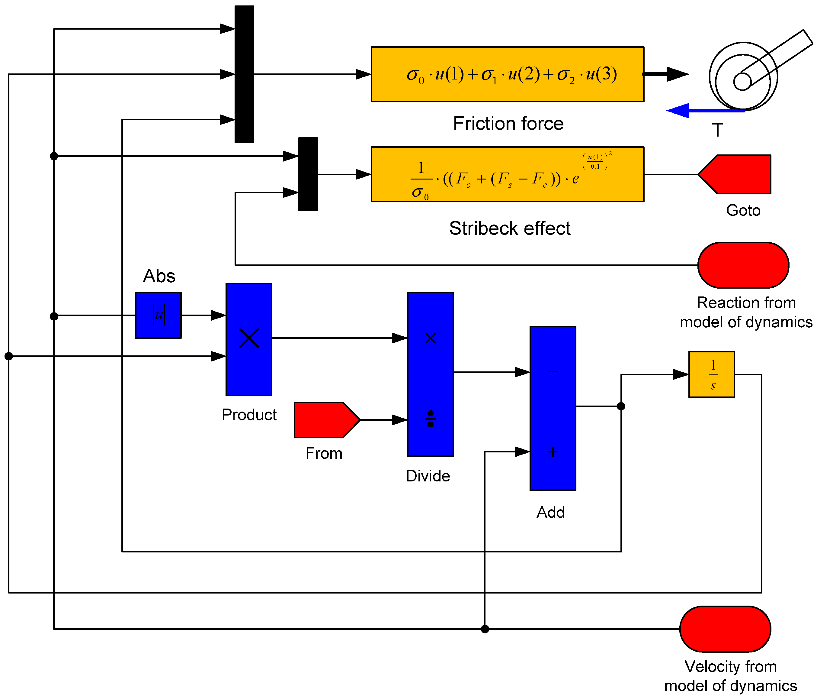
3.10. The LuGre Friction Model
The differential equation of dynamics including the LuGre’s friction model is stated as
where
The Stribeck effect describes the following equation:
where
The block diagram to which Equations (30)–(32) describing the LuGre model have been transformed is shown in
Figure 8.
3.11. Finite Element Method Model
A discrete model of the RCM mechanism of a surgical robot has been created for FEM analysis using the von Mises energy hypothesis. The model consists of 11,832 degrees of freedom and was discretized from the continuous continuum using a Solid 186 four-node element. The discrete model is illustrated in
Figure 9a.
The model was equipped with joints enabling motion to achieve the workspace required in MIRS technology. The model was solved using an iterative solver. Material data for the structural material of the model are included in
Table 1.
The numerical model allows importing any material with known material coefficients.
3.12. Multi-Criteria Optimization Model
The research task was undertaken to formulate a multi-objective optimization model containing criteria defined on the basis of significant physical phenomena that occur in the stationary and moving state of the RCM mechanism of a surgical robot. These phenomena include mechanical resonance, elastic buckling, and static and dynamic stress. The stress issues are determined based on the von Mises hypothesis. Static and dynamic issues are included in one vector function.
During numerical simulations using FEM, the cross-sections of the structure are modified. The load-bearing capacity of the RCM mechanism is determined by two characteristics, namely material properties and link geometry. The FEM numerical model allows for the determination of stresses, displacements, deformations, static and dynamic safety factors, buckling coefficient, natural frequencies of vibration, and endoscope tip displacement.
The selection of criteria for the vector function was based on long-term studies of the construction of surgical robots Robin Heart 1, Robin Heart 2, and Robin Heart Vision produced at the Foundation for the Development of Cardiothoracic Surgery named after Prof. Zbigniew Religa, illustrated in
Figure 10. The natural frequency associated with the phenomenon of resonance and sudden increase in the amplitude of endoscopic tip displacement was taken into account. This phenomenon may occur in the RCM mechanism structure due to the forced vibrations from the joints and endoscopic tool servomotors, tissue removal forces, the influence of the trocar, start-up and braking phenomena, and sudden movements at varying accelerations. The surgical robot system operates within the resonance curve ranges. The described work is related to the loss of endoscope positioning accuracy relative to soft tissue.
The buckling coefficient is associated with the phenomenon of elastic buckling, which is related to the appearance of the Euler critical force on the slender sleeve of the endoscope. Buckling deformation can cause significant structural deformation of the endoscope. The safety factor in statics is related to the deformation of the robot structure in the state of positioning the tool over the tissue and is related to the yield strength and stress reduced according to the von Mises energy hypothesis. The significant load in this case is the force of gravity and the value of the impact force on the soft tissue. The factor of safety in transient dynamics involves solving the full equation of dynamics, taking into account the history of deformations from previous moments of numerical computation time. The mass affects the value of the force of gravity and inertia, especially with respect to the RCM mechanism structure due to its construction and the location of the centers of mass relative to the axis of the two rotations of the successive joints. The spherical movement of the endoscopic instrument is achieved by two rotational motions of the RCM in the first and second connectors. The objective should be to ensure that the center of mass of the links is as close as possible to the two axes of rotation and that the links are made of lightweight and durable construction materials. However, moving the center of gravity of the mechanism as close as possible to the axis of rotation is difficult due to the requirements of the working space. Therefore, it is necessary to strive to reduce the cross-sections of the links.
The mechanical assumptions for the numerical computational model are as follows:
The model is numerically solved using the (NSGA-II) algorithm;
Small displacements are assumed in static problems;
The material is a discretized continuous continuum described by Young’s modulus, Kirchhoff’s modulus, and Poisson’s ratio. The model is isotropic;
Insignificant interactions have been omitted;
It is assumed that all bodies in the model are deformable.
The objective function was adopted as follows:
The following restrictions were adopted:
Knowing that
—static safety factor criterion;
—first natural frequency criterion;
—buckling coefficient;
—dynamic safety factor criterion;
—displacement of the end of the endoscope;
—dimension related to the diameter;
—dimension related to the diameter;
—dimension related to the diameter.
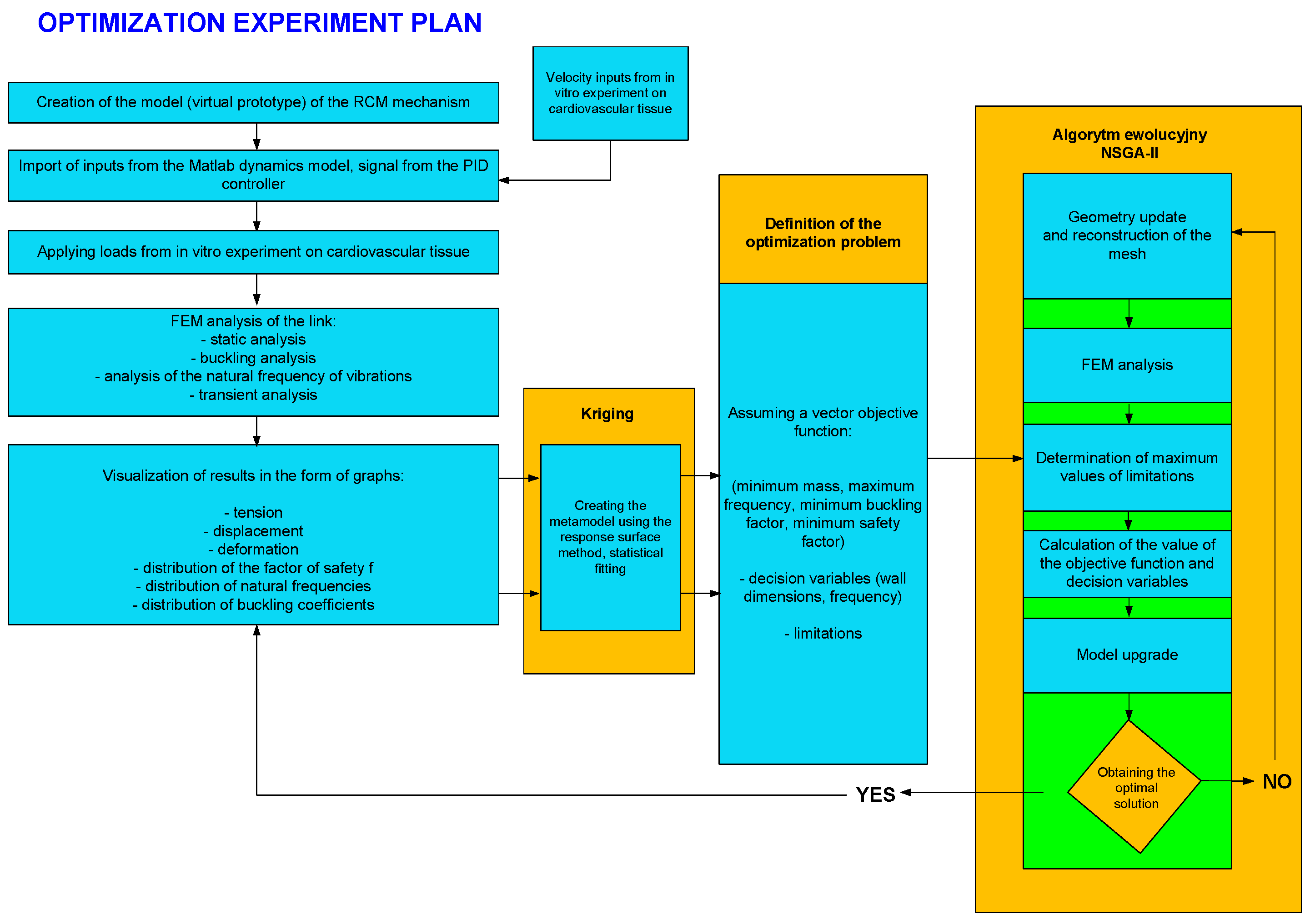
The plan of the optimization experiment is illustrated in
Figure 11. Its basic elements include blocks for inputting variables to the FEM model, a block for creating response surfaces using the Kriging method, and a block for the evolutionary algorithm (NSGA-II).
After solving the optimization problem, it is possible to generate results in the form of graphs and tabular values.
4. Results
In this paragraph, the basic strength characteristics obtained from the optimization model calculation are determined. These characteristics include, for example, stress values during resonance, which indicate the volume of material exposed to destruction, and stress values during buckling. Stress reduced according to the energy hypothesis of von Mises is also important, which manifests itself in the static and dynamic safety factor. The energy deformation values for the discussed numerical analyses, which illustrate the places where potential energy is stored in the structure, are also illustrated. In addition, Pareto fronts are presented, which form the basis for calculating the multi-criteria function in the optimization problem, as well as response surfaces obtained using the Kriging method that determine the influence of geometric features on the vector objective function criteria. Basic characteristics related to the velocity values for the RCM mechanism joints obtained using CMOS sensors are also shown.
4.1. Velocity Characteristics during the In Vitro Experiment
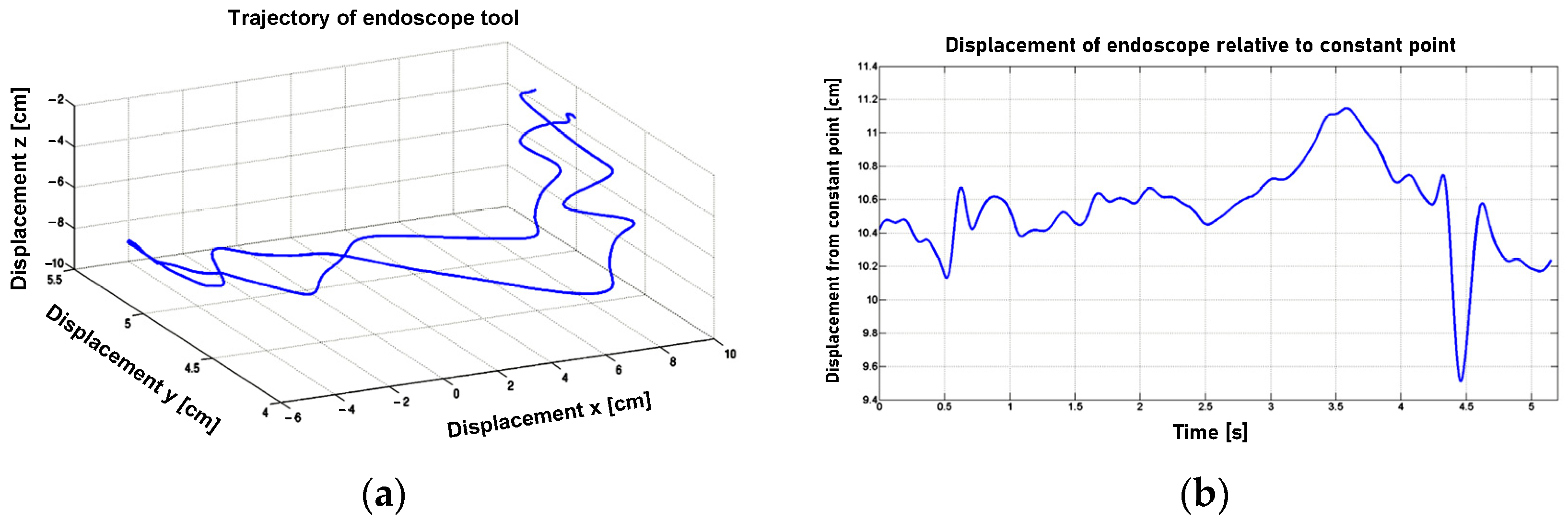
After applying the finite difference method to the discrete trajectory data presented in
Figure 12, the linear velocity profile of the endoscopic tool tip was obtained. This tool tip was positioned by the surgeon in relation to the tissue and used to incise it. The in vitro experiment data were then smoothed (excluding the random component) using the Savitzky–Golay filter, with the filter parameters optimally selected using the Durbin–Watson criterion. The filter parameters are considered optimal when the Durbin–Watson criterion reaches a value of 2. Next, the angular velocity of the endoscopic spherical movement was determined after passing through the spherical joint, which simulates a trocar in the outer shells of the body.
The displacement of the tool relative to the trocar is illustrated in
Figure 12b. The angular velocity in the form of waveforms in relation to the X, Y, and Z axes of the coordinate system adopted in the spherical joint is shown in
Figure 13.
The final values of velocities as inputs for joints of the RCM mechanism are in the
Table 2.
The values presented in
Table 2 were determined for the positioning movements of the surgical tool relative to the tissue and for situations related to incising soft heart tissue during the in vitro experiment. The values from
Table 2 were used as input data for the dynamics model with the drive system, control system, and Lugre motion resistance model.
4.2. Strength Characteristics Obtained during Numerical Analysis and Multi-Objective Optimization Experiment
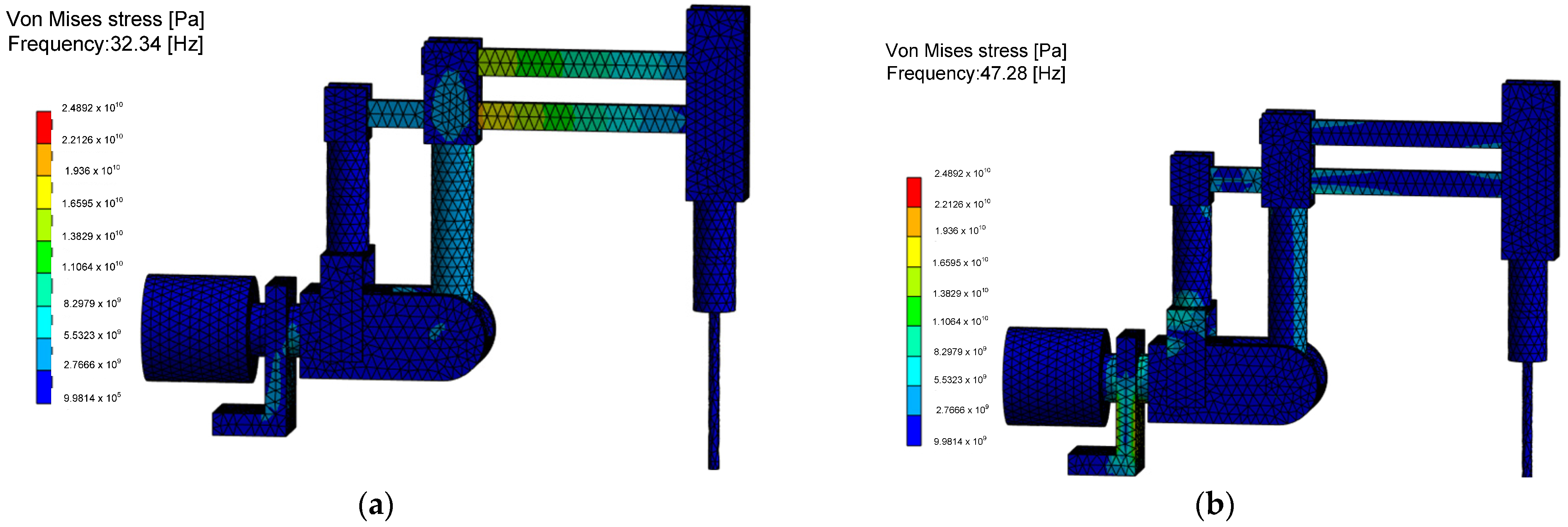
The reduced stress values, according to von Mises’ strain energy hypothesis, indicating the probable locations of structural damage during the negative resonance phenomenon, are shown in
Figure 14. It is found that for the RCM mechanism, in the analyzed configuration, the highest resonance stresses at the first natural frequency appear in the two links connecting the endoscopic tool drive mechanism with the second degree of freedom column. In the case of the analysis of the second natural frequency, based on the FEM results, it was found that dangerous resonance stresses concern the columns and joints of the second degree of freedom and the base with significant dimensions, which cannot undergo the phenomenon of plasticization or decohesion. Determining stress values is an important issue for the RCM mechanism as it is a complex system of linkages and joints difficult to assess with analytical methods. The created numerical model allows us to answer the question of how many times the applied load system can be increased without losing the safe value of the parameter, which is the load capacity of the structure in case of analyzing the influence of various physical phenomena.
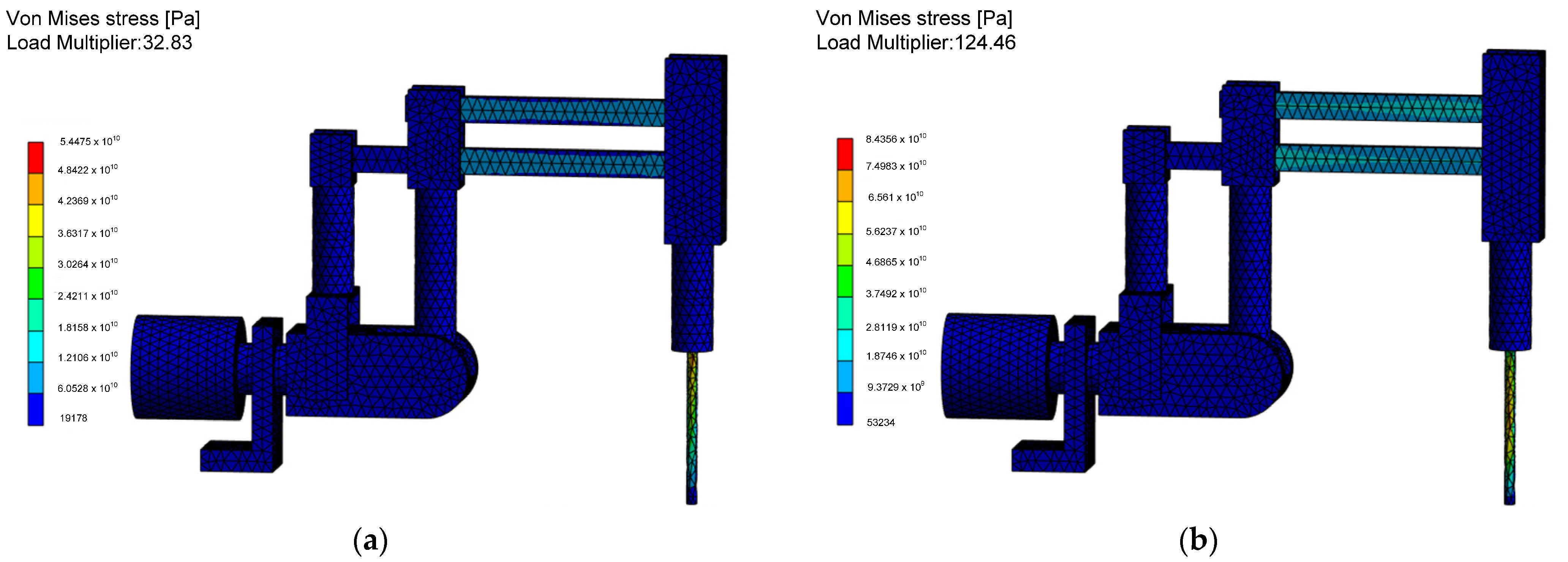
The most important quantities are stress in static and dynamic states and stress during the surgical robot construction being on the resonance curve, which results in an increased positioning error of the effector. The reduced von Mises stress values during the occurrence of the linear buckling phenomenon associated with the critical Euler force applied to the structure are shown in
Figure 15.
After analyzing the buckling results, it was observed that the slender elements connecting the endoscope drive mechanism with the first degree of freedom column, as well as the slender endoscope sleeve, are susceptible to buckling. However, due to the significant buckling coefficients, it is concluded that the elements of the surgical robot will not experience buckling deformation. Instead, they will deform under applied loads due to the resulting stresses. Therefore, it is advisable to consider adjusting their dimensions using an optimization algorithm to ensure a significant margin of safety against buckling.
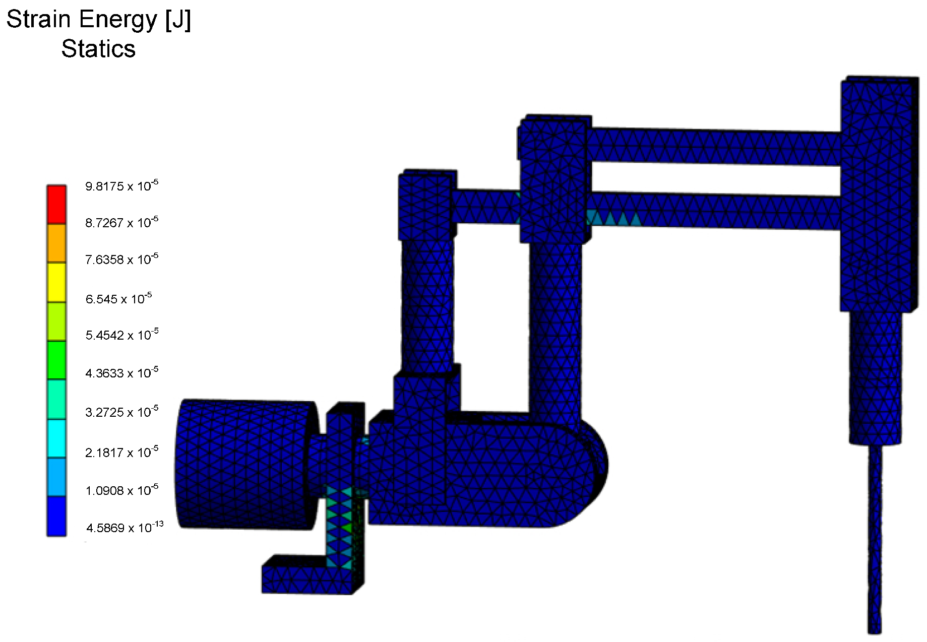
The values of strain energy, indicating changes in the volume of the structure for both static and unsteady states analyses, are depicted in
Figure 16. These values are associated with the storage of potential energy due to external forces. Based on the data obtained, it was determined that the maximum elastic deformation energy is stored in the base of the RCM mechanism and in the lower link connecting the endoscopic tool drive with the column of the first degree of freedom. Particularly important is the determination of safety factor values for static and unsteady state analyses, especially during the motion of the RCM mechanism. The desired safety factor values were obtained by solving the multicriteria optimization problem for the RCM mechanism. According to national standards for medical devices, the described values should be relatively high, as it was assumed in this study, preferably greater than four.
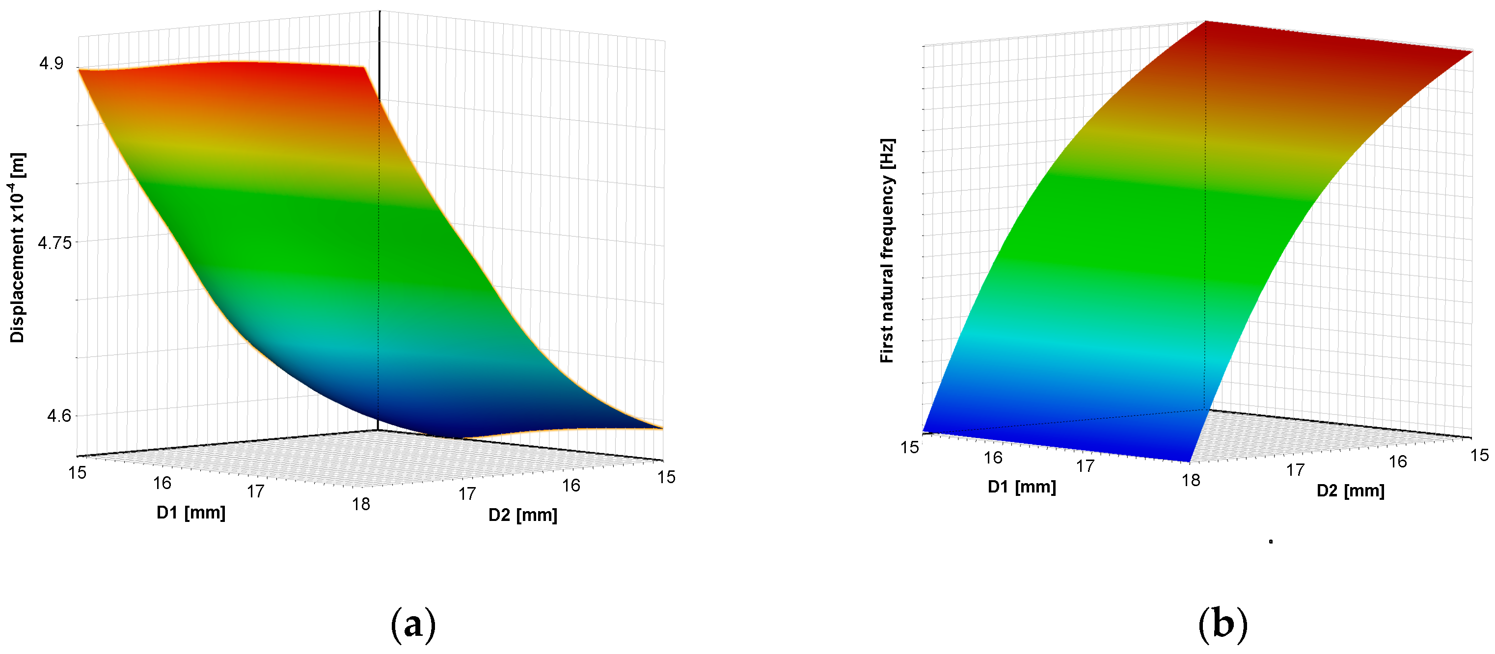
The response surfaces (meta-models) dependencies of criteria on geometric dimensions of RCM are shown in
Figure 17.
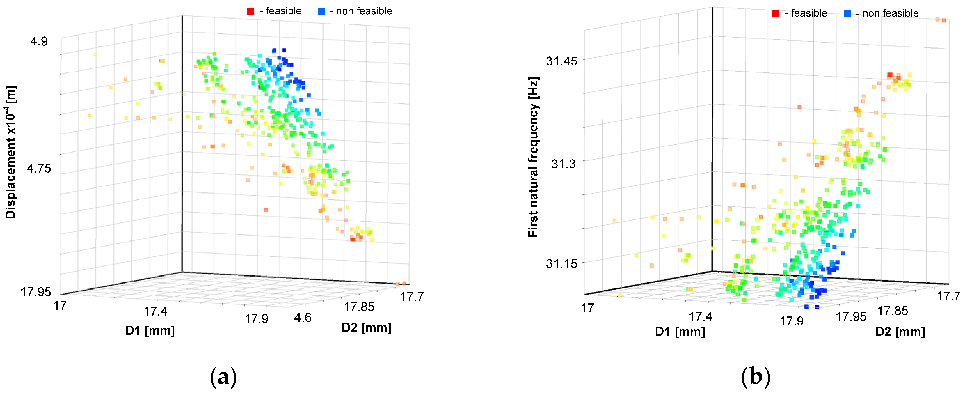
The Pareto fronts, which form the basis for multi-objective optimization solved by the NSGA-II genetic algorithm, are shown in
Figure 18.
The optimal values of the dimensions of the surgical robot achieved using the response surface method and NSGA-II genetic algorithm are . The dynamics and statics factor of safety are greater than four, and the first natural frequency , buckling coefficient , and displacement of the tool . The optimal solution of the multi-criteria function was reached after 20 iterations.
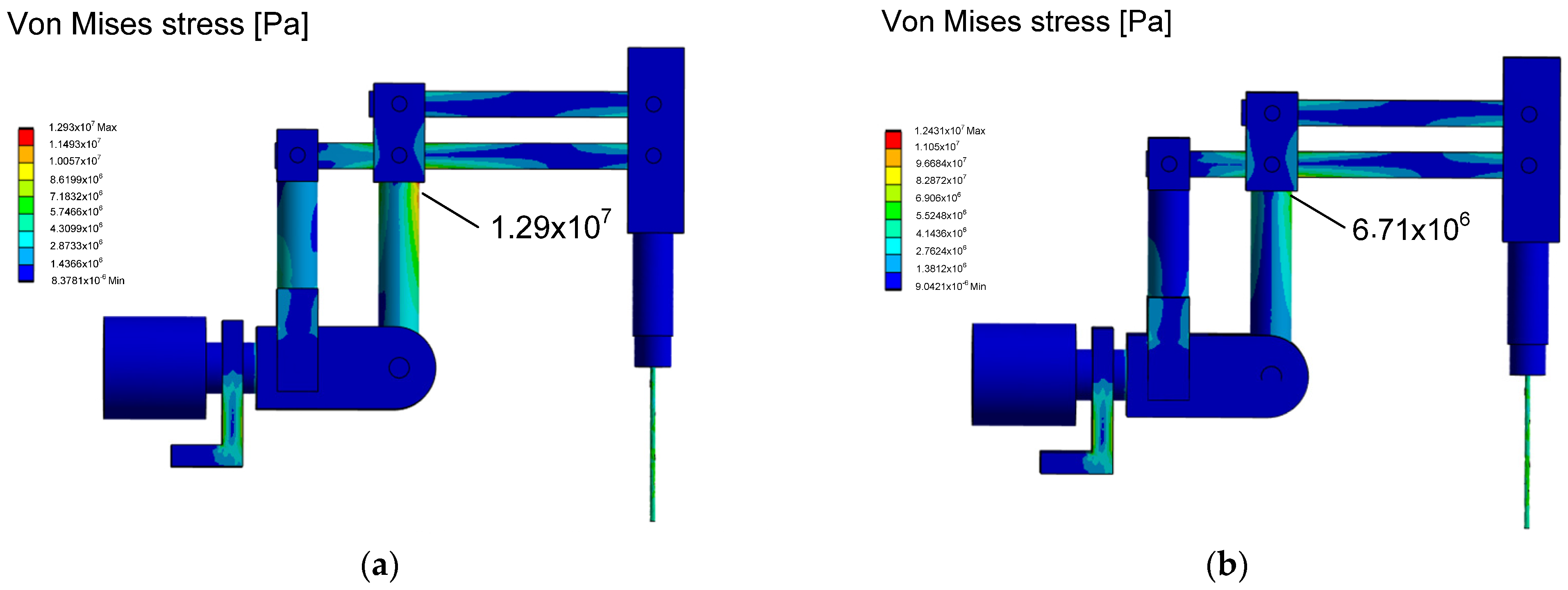
The stress reduction, according to the von Mises hypothesis, for the dimensions adopted in the initial design phase and after the numerical optimization experiment is illustrated in
Figure 19. A decrease in stress was observed in the column of the first degree of freedom of the RCM mechanism, leading to increased durability and reliability of the surgical robot. Additionally, the assumed optimization quality indicators were achieved within the accepted constraints.
5. Discussion
In the discussion section, implications of the new approach on finding optimal dimensions in the structure of a surgical robot are presented. It is important that the built mechatronic model has a high approximation to the real object. Therefore, it is essential to add the actuator system, control system, and resistance model to the discussed model. Such models can be efficiently built using the block diagram method in the Matlab/Simulink environment, allowing for interactive changes in their parameters and effective simulation. The problem of building an optimization model is based on assuming that the geometric dimensions are the design features of the surgical robot. The model was built using modern CAx tools in the field of computer-aided design methods. Building optimal models is a current issue addressed in many scientific works. However, the parameters of the adopted model are crucial; in this case, they are based on resonance values, buckling, and allowable stress values calculated based on von Mises’ hypothesis. The research goal was achieved using a heuristic method, the NSGA-II algorithm based on evolutionary issues, which is resistant to local extremes.
Various methods were used to solve second-order linear differential equations, such as the Runge–Kutta method to solve the problem of dynamic moments with a DC actuator, a PID controller, and a LuGre friction model. The Newmark method was used to solve the problem of dynamics with consideration of inertia, viscous damping, and elasticity. The Lanchos method was used to solve the buckling problem for large symmetric systems. The Newton–Raphson method was used to solve FEM problems. The frequency domain problem was solved using the von Mises iteration method, while the strength calculations were based on the von Mises energy hypothesis.
The optimal design method, utilizing a vector function, allows for the simultaneous consideration of several criteria crucial for the correct operation of the surgical robot in both static and dynamic states. This approach proves advantageous for designers as it enables them to attain the optimal result—the best possible results within the existing constraints—while accommodating numerous physical phenomena affecting the structure of the surgical robot. Consequently, it accurately replicates actual operating conditions and achieves the desired extremes of quality indicators within the vector function.
Incorporating inputs from experiments on cardiovascular tissue facilitates numerical inferences based on created mathematical models, closely resembling reality after implementing recorded data as forcings. Analyzing the course of physical phenomena experimentally on a real object, without mathematical models, fails to provide critical values ranges (e.g., stress, strain, natural frequency) necessary for the surgical robot’s correct operation.
A particularly crucial quality indicator for a surgical robot is its natural frequency. Considering this frequency along with input frequencies (e.g., from servomechanisms operation, tissue interactions, beating heart, automatic cardiac surgical instruments, and surgeon’s hand tremor), the geometric dimensions of the robot’s links are selected to ensure the required positioning accuracy—a key parameter ensuring functionality. Simultaneously, less important criteria (e.g., buckling coefficient range) included in the optimization model are examined against adopted assumptions.
Adopting the proposed design methodology enables the creation of design documentation for an efficient prototype of a surgical robot without necessitating an expensive research laboratory—a significant advantage of the adopted experimental and mathematical modeling method. The methodology, developed over many years of experience (over 20 years of experimental practice and numerical research on several surgical robot prototypes), represents a valuable repository of experimental data, knowledge, and skills, essential for creating a functional and optimal surgical robot design, according to the authors.


