Article

Nonlinear-Observer-Based Neural Fault-Tolerant Control for a Rehabilitation Exoskeleton Joint with Electro-Hydraulic Actuator and Error Constraint

1
School of Mechanical Engineering, Xihua University, Chengdu 610039, China
2
School of Electrical Engineering and Electronic Information, Xihua University, Chengdu 610039, China
*
Author to whom correspondence should be addressed.
Appl. Sci. 2023, 13(14), 8294; https://doi.org/10.3390/app13148294
Submission received: 27 April 2023 / Revised: 27 June 2023 / Accepted: 5 July 2023 / Published: 18 July 2023
(This article belongs to the Special Issue Applications of Robotics in Disease Treatment and Rehabilitation)

Abstract

:
The rehabilitation exoskeleton is an effective piece of equipment for stroke patients and the aged. However, this complex human–robot system incurs many problems, such as modeling uncertainties, unknown human–robot interaction, external disturbance, and actuator fault. This paper addresses the adaptive fault-tolerant tracking control for a lower limb rehabilitation exoskeleton joint driven by an electro-hydraulic actuator (EHA). First, the model of the exoskeleton joint is built by considering the principle of the hydraulic cylinder and the servo valve. Then, a novel disturbance-observer-based neural fault-tolerant control scheme is proposed, where the neural network and disturbance observer are incorporated to reduce the influence of the the nonlinear uncertainties and disturbance. Meanwhile, a barrier Lyapunov function is constructed to ensure the stability of the closed-loop system. Finally, comparative simulations on an exoskeleton joint validate the effect of the proposed control scheme.

1. Introduction

Powered exoskeleton is indispensable in affording rehabilitation training for stroke and elderly patients due to its mechanical durability and control intelligence. The rehabilitation exoskeleton is a human–robot coupled highly complex system with the presence of nonlinearities and uncertainties. To cope with this, exoskeleton motion control aiming to acquire good rehabilitation effects has been widely reported in the literature [1,2]. Fuzzy control for assistant rehabilitation is proposed in [3], where a user-experience-based method is used for designing the product. Adaptive sliding control is presented for a cable-driven exoskeleton in [4]. The joint of the exoskeleton robot is actuated by pneumatic muscle actuators. In [5], an assist-as-needed control scheme is designed for an upper limb exoskeleton driven by brushed DC motors. Integrating with the user’s dynamics, a forearm exoskeleton with 3 degrees of freedom is introduced in [6], and an adaptive PID-like controller with lower mean square error is implemented in the exoskeleton to perform the trajectory tracking task. A soft elbow exoskeleton driven by a tendon-sheath actuator is developed in [7], where a neural network is used to identify the elbow torque. Most of the aforementioned exoskeletons are driven by electrical motor and pneumatic actuators. Since the weight of the lower limb is relatively heavy, the EHA is more suitable for providing enough assistance torque due to its high power-to-weight ratio. However, the complicated nonlinearities raised with the EHA pose a significant threat to the stability and safety of the human–robot system.
Actuator failure is one of the critical factors that affect the stability and safety of the rehabilitation exoskeleton. The fault-tolerant control of nonlinear systems has received increasing attention [8]. Adaptive fault-tolerant control is proposed for three-phase PMSM drivers, where the fault-tolerant reference current can be used without failure detection [9]. Fault-estimation-based attitude control is studied for spacecraft with input saturation and disturbance in [10]. The fault-tolerant performance is ensured by establishing a finite-time sliding mode controller. Dual temperature control and the fault diagnosis method are proposed for the continuous stirred-tank reactor in [11]. Both passive and active fault-tolerant control abilities are realized for its cooling water system. In [12], a hierarchical structure-based tracking control is presented for laboratory helicopters, and edge-based adaptive fault-tolerant controllers are carried out to handle the bidirectional interactions. Distributed fault-tolerant control is studied for a class of industrial processes in [13]. In this work, a setpoint redesigned method is utilized to acquire the collaborative fault-tolerant controller via resolving the linear matrix inequalities. Although the development and application of adaptive fault-tolerant control have also received remarkable attention in the fields of industrial manufacturing, combustion gas engine, feed-water system, aero-engine, wind turbine, and underwater vehicles [14], its study and exploration on exoskeleton with EHA still remain superficial. In this paper, the effectiveness loss and bias faults are considered and handled for the exoskeleton robot so that stable and safe rehabilitation therapy can be pursued.
Rehabilitation therapy, such as the assisted rehabilitation of the training medium stage, requires compact physical contact between the human limbs and the mechanical legs. A constraint-based control design is able to prevent damage to human limbs caused by unexpected tracking error. Tee et al., developed a barrier Lyapunov function (BLF) to deal with the output tracking error constraint problem for nonlinear systems [15]. It has became the most attractive option for the system with an error constraint because the BLF will approach infinity when its arguments are close to the defined boundary. In [16], the second-order sliding mode constraint control is designed for a class of nonlinear system, where a power integrator technology is integrated into the fuzzy logic to approach the uncertain bounds. Sun et al. studied the output feedback constraint output regulation for an electrostatic torsional micromirror with an unknown exosystem [17]. The output regulation constraint is tackled by integrating a BLF into the control design. Zhao et al. explored the trajectory tracking of a marine surface vessel, and a symmetric BLF was adopted to meet the multiple output constraint conditions [18]. The BLF-based control design is extensively applied in robot systems. Hu et al. investigated the practical tracking of a dual-arm robot with an output constraint [19]. The robot’s original error constraint was satisfied by combining with BLF and the backstepping technique. Liu et al. studied the time-varying output constraint problem of an uncertain n-link robot, and the time-varying BLF was employed to prevent the violation of the error constraint [20]. Due to its distinct advantage of constraint management, the BLF is also adopted in this article to enhance the safety of the human–exoskeleton rehabilitation training.
Modeling uncertainties and external disturbance, which are ubiquitous in the EHA, inevitably reduce the control performance of the rehabilitation exoskeleton. Benefiting from the universal approximation ability, the neural network has widely been used in dealing with nonlinear uncertain systems in recent years [21]. Li et al. studied the adaptive tracking control issue of a nonlinear interconnected system, and a fixed-time neural control structure was constructed to identify the unknown uncertainties [22]. In [23], the terminal sliding mode control of a second-order nonlinear system was studied, where the multiple hidden layer recurrent neural network was utilized to improve the dynamic approximation performance. Funnel dynamic surface control for a time delay permanent magnet synchronous motor was proposed in [24]. The multiple unknown uncertainties of the permanent magnet synchronous motor were approached by the RBF neural networks. In [25], kinematics model identification and the movement control of a modular robot were addressed. A dynamic Elman network based novel fast learning neural structure was presented to identify the nonlinear kinematics model of the robot. To overcome the insurmountable influence of external disturbance, several types of observers are reported in the literature. Reference [26] designed a nonlinearly parameterized observer for a sensorless induction motor by introducing a parameter-dependent transformation. A distributed adaptive output observer was designed for the leader–follower multiagent systems in [27]. This method requires only the output information of the leader system, and it is capable of reducing the dimension of the agents. The anti-disturbance control of a nonlinear system with multisource uncertain disturbances was addressed in [28]. The observer was designed separately from the controller to approach the disturbance by using partial information. The adaptive control of a class of stochastic systems subject to heterogeneous disturbances is studied in [29], and an adaptive nonlinear disturbance observer is proposed to estimate the non-harmonic disturbance.
Accordingly, this paper pays attention to the fault-tolerant trajectory tracking control of a rehabilitation exoskeleton with EHA. Different from the existing studies [4,6,7,30], the actuator fault is considered in this article for ensuring the safety of the rehabilitation therapy. Moreover, a disturbance observer is incorporated into the controller to improve the rehabilitation effect.
The remaining sections of this article include the following aspects. Section 2 describes the dynamics of the rehabilitation exoskeleton with EHA and offers some integral preliminaries. Section 3 expatiates the control development and the main results via Lyapunov theory. Section 4 performs the simulation studies of the proposed controller. Section 5 concludes the article.

2. Preliminaries

2.1. The EHA Exoskeleton

A lower limb exoskeleton joint equipped with an EHA is displayed in Figure 1. The EHA, which contains a hydraulic cylinder and a servo valve, is mounted on the knee joint of the exoskeleton’s mechanical leg. The movement of the piston rod is ruled through regulating the pressure and direction of the hydraulic oil under certain valve control of the orifice opening. According to the Newton’s second law of motion, the movement of the EHA can be narrated as [30]
m y ¨ p = P 1 S 1 P 2 S 2 c y ˙ p f e ( t ) f h ( t ) ,
where m stands for the equivalent load of the end of the piston rod, y p stands for the displacement of the piston rod, P 1 and P 2 represent the pressures of the non-rod chamber and the rod chamber, S 1 and S 2 represent the piston areas of the non-rod chamber and the rod chamber, c denotes the damping and viscous friction coefficient of the cylinder wall, f e ( t ) denotes the external disturbance, and f h ( t ) denotes the human–exoskeleton interaction.
The exoskeleton joint is governed by the piston rod of the hydraulic chamber, the hydraulic fluid dynamics of the hydraulic chambers are given as [31]
    P 1 ˙ = β e V 1 + S 1 y p Q 1 S 1 y ˙ p Q l i ( t ) Δ l e 1 ( t )     P 2 ˙ = β e V 2 S 2 y p S 2 y ˙ p Q 2 + Q l i ( t ) Δ l e 2 ( t )
where β e is the effective hydraulic fluid bulk modulus, V 1 and V 2 are the initial volumes of the two chambers, Q 1 and Q 2 are the flow rates of two chambers, Q l i ( t ) is the cylinder’s internal flow leakage, and Δ l e 1 ( t ) and Δ l e 2 ( t ) are the cylinder’s external flow leakages.
As the rehabilitation motion frequency is much lower than the bandwidth of the servo valve, the dynamics of the servo valve is neglected. Based on the linear flow/signal gain property of the proportional valve, the flow rates Q 1 and Q 2 are linearly proportional to the actual control signal of the servo valve u [31]:
Q 1 =       k s u ,   y ˙ p 0 ,     ρ k s u ,   y ˙ p < 0 , Q 2 =     k s ρ u ,   y ˙ p 0 ,   k s u ,   y ˙ p < 0 ,
where k s is the valve flow/signal gain, and ρ S 1 / S 2 is the area ratio at both ends of the piston.
When the exoskeleton undergoes long-term and continuous rehabilitation, unanticipated actuator faults may take place such that the actual control input of the servo valve u is not equal to the designed control input u c . The considered actuator faults are described as
u = h ( t h , t ) u c + δ ( t δ , t ) .
where u c is the commanded control input that needs to be designed, h ( t h , t ) stands for the healthy indicator that demonstrates the effectiveness of the actuator, δ ( t δ , t ) stands for the uncontrollable part of the valve input, and t h and t δ are the time instants when the actuator faults occur.
Considering the entire system (1)–(4) and defining the state variables as [ x 1 , x 2 , x 3 ] T [ y p , y ˙ p , ( P 1 A 1 P 2 A 2 ) / m ] T , the state space model of the rehabilitation exoskeleton joint is demonstrated as
  x ˙ 1 = x 2 ,   x ˙ 2 = x 3 c m x 2 g 1 ( t ) g 2 ( t ) ,   x ˙ 3 = g 3 ( x 1 , x 2 ) + g 4 ( x 1 ) h u c + g 5 ( t ) + δ ( t δ , t ) ,     y = x 1 ,
where
g 1 ( t ) = f e ( t ) m , g 2 ( t ) = f h ( t ) m ,
g 3 ( x 1 , x 2 ) = S 1 2 β e y ˙ p m ( V 1 + S 1 y p ) S 2 2 β e y ˙ p m ( V 2 S 2 y p ) ,
g 4 ( x 1 ) = S 1 β e k s m ( V 1 + S 1 y p ) + S 2 β e k s m ρ ( V 2 S 2 y p ) ,
g 5 ( t ) = S 1 β e [ Q l i ( t ) + Δ l e 1 ( t ) ] m ( V 1 + S 1 y p ) S 2 β e [ Q l i ( t ) Δ l e 2 ( t ) ] m ( V 2 S 2 y p ) ,
Remark 1.
The actuator fault (4) is universally applied in the literature. The healthy indicator h ( t h , t ) is regarded as the multiplicative coefficient and δ ( t δ , t ) is regarded as the additive or bias fault. The actuator is fully healthy if h ( t h , t ) = 1 and δ ( t δ , t ) = 0 . If h ( t h , t ) < 1 , the actuator suffers from the effectiveness loss.
Remark 2.
To ensure that the system is controllable, the healthy indicator h ( t h , t ) satisfies 0 < h ( t h , t ) 1 . Meanwhile, the additive fault is bounded, i.e.,   δ ¯ > 0 , s.t. δ < δ ¯ < + for all t ( 0 , + ) .

2.2. Problem Formulation

The rehabilitation therapy is performed by moving the patient’s injured limbs using the mechanical leg of the exoskeleton. Thus, the exoskeleton leg needs to track the given training trajectory as closely as possible through regulating the control input of the servo system u c . In system (5), the output is the rod displacement y p instead of the joint trajectory θ . It should be solved by geometric transformation before designing the controller. From Figure 1, the exoskeleton joint angle θ is divided into three angles
θ = θ 2 ( x 1 ) + θ 1 + θ 3 ,
where θ 1 and θ 3 are constants, which are determined by the mechanical parameters of l 1 to l 4 , and θ 2 is directly relevant to the rod displacement y p and mechanical parameters l 5 to l 7 as follows:
θ 2 ( y p ) = arccos l 6 2 + l 5 2 ( y p + l 7 ) 2 2 l 6 l 5 ,
where l i ,   i = 5 , , 7 are the known mechanical length.
Combining Equations (10) and (11), and Figure 1, the joint angle θ is exclusively determined by y p . It means that tracking the given rehabilitation trajectory can be achieved by tracking the system state x 1 . Hence, the control objective of the rehabilitation exoskeleton with EHA in this paper is to design a fault-tolerant controller so that the rod displacement y p can track the desired displacement y p d . To facilitate the controller design, the follow lemmas and assumptions are introduced.
Lemma 1
([18]). For vectors b R n with elements b i > 0 and c R n , if | c | < | b | , then the following relationship holds:
ln b T b b T b c T c c T c b T b c T c .
Lemma 2.
If a smooth and continuous function N ( t ) is bounded with | | N ( t ) | | n ,   t [ t 1 , t 2 ] , then N ˙ ( t ) is always bounded.
Proof. 
According to the differential mean value theorem, there exists n [ n 1 , n 2 ] such that N ˙ ( n ) = N ( n 2 ) N ( n 1 ) / ( n 2 n 1 ) ,   [ n 1 , n 2 ] [ t 1 , t 2 ] . At the same time, 2 n N ( n 2 ) N ( n 1 ) 2 n since | | N ( t ) | | n ; hence, N ˙ ( n ) is bounded. Owing to n [ n 1 , n 2 ] [ t 1 , t 2 ] , the boundedness of N ˙ ( t ) is ensured   t [ t 1 , t 2 ] . □
Assumption 1.
For the exoskeleton with EHA, the unknown external disturbance f e ( t ) and human–exoskeleton interaction f h ( t ) are bounded, i.e., there exist f e ¯ > 0 and f h ¯ > 0 , s.t. | f e ( t ) | f e ¯ and | f h ( t ) | f h ¯ ,   t 0 . Furthermore, the desired rehabilitation trajectory is continuous, smooth and bounded.
Remark 3.
Given a desired rehabilitation trajectory θ d , the desired displacement y p d can be calculated by θ 2 ( y p d ) = θ d θ 1 + θ 3 and (11). In addition, the one-to-one mapping between θ d and y p d is guaranteed since the length parameters l 1 , , l 7 are positive.

3. Control Design and Main Results

The fault-tolerant control scheme of the rehabilitation exoskeleton with EHA is designed in this section by applying the backstepping technique. The neural network and disturbance observer are incorporated into the exoskeleton controller for coping with the modeling uncertainties, human–robot interaction, and external disturbance. In the meantime, a barrier Lyapunov function is introduced to construct the adaptive fault-tolerant controller so that the error constraint can be ensured.

Controller Development

Backstepping is a method with a recursive structure for constructing stable controls for irreducible subsystems. Based on the Lyapunov theorem, an intermediate virtual controller is designed for each subsystem, which is “extrapolated” to the entire system, thereby designing the overall control law of the system. The backstepping controller is designed via the following steps.
Step 1. Define three error variables as
  e 1 = x 1 y p d ,   e 2 = x 2 μ 1 ,   e 3 = x 3 μ 2 ,
where y p d stands for the desired displacement of the piston rod which can be uniquely computed by the geometric transformation (10) and (11), and the desired joint angle θ d . μ 1 and μ 2 are the intermediate virtual control laws to be designed. The time derivative of the first error variable e 1 is
e ˙ 1 = x ˙ 1 y ˙ p d = x 2 p ˙ p d = e 2 + μ 1 y ˙ p d .
In order to cope with the error constraint, choose the barrier Lyapunov function as
V 1 = 1 2 ln k c 2 k c 2 e 1 2 ,
where k c is a positive tolerance of the error constraint. Differentiating V 1 , we have
V ˙ 1 ( t ) = e 1 e ˙ 1 k c 2 e 1 2 = e 1 ( e 2 + μ 1 y ˙ p d ) k c 2 e 1 2 .
Design the value of μ 1 as
μ 1 = k 1 e 1 + y ˙ p d ,
where k 1 > 0 is the control parameter. Combining (17) and (16), we obtain
V ˙ 1 ( t ) = k 1 e 1 2 k c 2 e 1 2 + e 1 e 2 k c 2 e 1 2 .
Step 2. Computing the time derivative of e 2 and using x ˙ 2 in (5) yields
e ˙ 2 = x ˙ 2 μ ˙ 1 = x 3 g 1 ( t ) c m x 2 g 2 ( t ) μ ˙ 1 = e 3 + μ 2 g 1 ( t ) c m x 2 g 2 ( t ) μ ˙ 1 .
In the subsystem (19), g 1 ( t ) and g 2 ( t ) are unavailable due to the external disturbance f e ( t ) and human–robot interaction f h ( t ) being unmeasurable. Simultaneously, the time derivative of the virtual signal μ 1 will result in a ’differential explosion’ problem. Therefore, a nonlinear disturbance observer is developed to deal with it. Define
F = g 1 ( t ) g 2 ( t ) μ ˙ 1 ,
we can further simplify (19) as
e ˙ 2 = e 3 + μ 2 c m x 2 + F .
Using Lemma 2 and Assumption 1, it can be concluded that
| F ˙ |   ε ,
where ε > 0 . In order to design the disturbance observer, an auxiliary variable L is constructed as
L = F k o e 2 ,
where k o > 0 . Differentiating L yields
L ˙ = F ˙ k o [ e 3 c m x 2 + μ 2 + F ] .
Before calculating the value of F, the following updating law is designed to estimate L ,
L ^ ˙ = k o [ e 3 c m x 2 + μ 2 + F ^ ] ,
where F ^ is used to estimate F. According to (23), F ^ is designed as
F ^ = L ^ + k o e 2 .
Defining F ˜ = F F ^ and L ˜ = L L ^ , it can be concluded that
L ˜ = F k o e 2 ( F ^ k o e 2 ) = F F ^ = F ˜ .
Taking the time derivative of D ˜ leads to
F ˜ ˙ = L ˜ ˙ = L ˙ L ^ ˙ = F ˙ k o F ˜ .
In a bid to stabilize the subsystem (19), the virtual signal μ 2 is designed as
μ 2 = e 1 k c 2 e 1 2 k 2 e 2 + c m x 2 F ^
where k 2 is a positive control parameter to be chosen. Based on (29) and (21) can be rewritten as
e ˙ 2 = e 1 k c 2 e 1 2 k 2 e 2 + e 3 + F ˜ .
Now, choosing the Lyapunov function as
V 2 = V 1 + 1 2 e 2 2 + 1 2 F ˜ 2 .
The time derivative of V 2 is
V ˙ 2 = V ˙ 1 + e 2 e ˙ 2 + F ˜ F ˜ ˙ .
Considering (18), (28), (30) and (32) can be simplified as
V ˙ 2 = k 1 e 1 2 k c 2 e 1 2 + e 1 e 2 k c 2 e 1 2 + e 2 ( k 2 e 2 e 1 k c 2 e 1 2 + e 3 + F ˜ ) + F ˜ ( F ˙ k o F ˜ ) = k 1 e 1 2 k c 2 e 1 2 k 2 e 2 2 + e 2 e 3 + e 2 F ˜ + F ˜ ( F ˙ k o F ˜ ) .
Step 3. In order to design the commanded control input u c , the time derivative of e 3 should be addressed.
e ˙ 3 = x ˙ 3 μ ˙ 2 = g 3 ( x 1 , x 2 ) + g 4 ( x 1 ) h u c + g 5 ( t ) + δ ( t δ , t ) μ ˙ 2
In the above equation, g 5 ( t ) is unknown because the flow leakages Q l i ( t ) , Δ l e 1 ( t ) , and Δ l e 2 ( t ) are unmeasurable. Considering that the additive fault δ ( t δ , t ) is unknown and the ’differential explosion’ of μ ˙ 2 , we design radial basis function neural networks (RBFNNs) to approximate them:
Ψ * T Ω ( X ) = g 5 ( t ) δ ( t δ , t ) + μ ˙ 2 π ( X )
where X = [ x 1 T , x 2 T , e 1 T , e 2 T , μ 2 ] are the input parameters of the neural networks. Ω ( X ) is the regressor basis function vector, Ψ * is the ideal weight, and π ( X ) is the approximation error. The updating law of the neural networks is
Ψ ^ ˙ = Ξ Ω ( X ) e 3 + λ Ψ ^ ,
where Ψ ^ is the estimate of Ψ * , Ξ is a positive-define constant matrix, and λ is a positive small constant. Introduce an intermediate auxiliary controller γ as
γ = k 3 e 3 + g 3 ( x 1 , x 2 ) Ψ ^ T Ω ( X )
and letting η = h 1 , the fault-tolerant controller is proposed as
  u c = g 4 ( x 1 ) 1 η ^ γ   η ^ ˙ = e 3 γ ϵ η ,
where ϵ is a positive parameter. Defining Ψ ˜ = Ψ ^ Ψ * , the subsystem (34) can be simplified as
e ˙ 3 = g 3 ( x 1 , x 2 ) + g 4 ( x 1 ) h u c + g 5 ( t ) + δ ( t δ , t ) μ ˙ 2 = g 3 ( x 1 , x 2 ) + g 4 ( x 1 ) h ( g 4 ( x 1 ) 1 η ^ γ ) + γ k 3 e 3 g 3 ( x 1 , x 2 ) + Ψ ^ T Ω ( X ) + g 5 ( t ) + δ ( t δ , t ) μ ˙ 2 = g 3 ( x 1 , x 2 ) + g 4 ( x 1 ) h ( g 4 ( x 1 ) 1 η ^ γ ) + γ k 3 e 3 g 3 ( x 1 , x 2 ) + Ψ ^ T Ω ( X ) Ψ * T Ω ( X ) π ( X ) = h η ^ γ + γ k 3 e 3 + Ψ ˜ T Ω ( X ) π ( X )
Let η ˜ = η ^ η , and consider the third Lyapunov function
V 3 = V 2 + 1 2 e 3 2 + 1 2 h η ˜ 2 .
Differentiating V 3 , and using (38) and (39), we obtain
V ˙ 3 = V ˙ 2 + e 3 e ˙ 3 + h η ˜ η ^ ˙ = V ˙ 2 + e 3 h η ^ γ + γ k 3 e 3 + Ψ ˜ T Ω ( X ) π ( X ) + h η ˜ ( e 3 γ ϵ η )
Notice that e 3 h η ^ γ + e 3 γ + h η ˜ e 3 γ = 0 , (41) can be rewritten as
V ˙ 3   = V ˙ 2 k 3 e 2 e 3 + e 3 Ψ ˜ T Ω ( X ) e 3 π ( X ) h η ˜ ϵ η
Consider the fourth Lyapunov function as
V 4 = V 3 + 1 2 Ψ ˜ T Ξ 1 Ψ ˜ .
Differentiating (43) yields
V ˙ 4 = V ˙ 3 + Ψ ˜ T Ξ 1 Ψ ˜ ˙ = V ˙ 3 + Ψ ˜ T Ξ 1 ( Ψ ^ ˙ Ψ ˙ * ) = V ˙ 3 + Ψ ˜ T Ξ 1 Ψ ^ ˙ .
Combining (33), (36) and (42), one has
V ˙ 4 = V ˙ 3 + Ψ ˜ T Ξ 1 Ψ ^ ˙ = V ˙ 2 e 2 e 3 k 3 e 3 2 + e 3 Ψ ˜ T Ω ( X ) e 3 π ( X ) h η ˜ ϵ η ^ + Ψ ˜ T Ξ 1 Ξ Ω ( X ) e 3 + λ Ψ ^ = V ˙ 2 e 2 e 3 k 3 e 3 2 e 3 π ( X ) h η ˜ ϵ η ^ + Ψ ˜ T λ Ψ ^ = k 1 e 1 2 k c 2 e 1 2 k 2 e 2 2 + e 2 e 3 + e 2 F ˜ + F ˜ ( F ˙ k o F ˜ ) e 2 e 3 k 3 e 3 2 e 3 π ( X ) h η ˜ ϵ η ^ + Ψ ˜ T λ Ψ ^ = k 1 e 1 2 k c 2 e 1 2 k 2 e 2 2 k 3 e 3 2 k o F ˜ 2 + e 2 F ˜ + F ˜ F ˙ e 3 π ( X ) h η ˜ ϵ η ^ + Ψ ˜ T λ Ψ ^
For (45), the following relationships hold:
e 2 F ˜ 1 2 e 2 2 + 1 2 F ˜ 2 F ˜ F ˙ 1 2 F ˜ 2 + 1 2 | F ˙ | 2 e 3 π 1 2 e 3 2 + 1 2 π 2 η ˜ ϵ η ^ η ˜ ϵ ( η ˜ + η ) ϵ η ˜ 2 + 1 2 ϵ η ˜ 2 + 1 2 ϵ η 2
1 2 ϵ η ˜ 2 + 1 2 ϵ η 2 Ψ ˜ T Ψ ^ = Ψ ˜ T Ψ ˜ + Ψ * = Ψ ˜ T Ψ ˜ Ψ ˜ T Ψ * Ψ ˜ T Ψ ˜ + 1 2 Ψ ˜ T Ψ ˜ + Ψ * T Ψ * 1 2 Ψ ˜ T Ψ ˜ + 1 2 Ψ * T Ψ *
Using Lemma 1 and (22), we obtain
V ˙ 4 k 1 ln k c 2 k c 2 e 1 2 ( k 2 1 2 ) e 2 2 ( k 3 1 2 ) e 3 2 ( k o 1 ) F ˜ 2 1 2 ϵ h η ˜ 2 1 2 λ | | Ψ ˜ | | 2 + 1 2 ε 2 + 1 2 π 2 + 1 2 h ϵ η 2 + 1 2 λ Ψ * T Ψ * ω V 4 + B
where
ω = min 2 k 1 , 2 k 2 1 , 2 k 3 1 , 2 k d 1 , ϵ , λ τ max ( Ξ 1 )
B = 1 2 ε 2 + 1 2 π 2 + 1 2 h ϵ η 2 + 1 2 λ Ψ * T Ψ *
Selecting the parameters as k 1 > 0 , k 2 > 1 / 2 , k 3 > 1 / 2 , k o > 1 / 2 , the stability of the system is ensured. The boundedness of the system errors is then addressed as follows. Multiplying (48) by e ω t yields
d d t V 4 ( t ) e ω t B e ω t
Integrating (51) obtains
V 4 ( t ) V 4 ( 0 ) B ω e ω t + B ω V 4 ( 0 ) + B ω
For e 1 , we obtain
1 2 ln k c 2 k c 2 e 1 2 V 4 ( 0 ) + B ω
| e 1 |   k c 2 1 e [ 2 ( V 4 ( 0 ) + B ! ) ]
Similarly to e 2 , e 3 , η ˜ , F ˜ , and Ψ ˜ , we have
| e 2 |     2 ( V 4 ( 0 ) + B ω ) ,     | e 3 |   2 ( V 4 ( 0 ) + B ω ) ,
| η ˜ |   2 ( V 4 ( 0 ) + B ω ) h 1 ,
| F ˜ |   2 ( V 4 ( 0 ) + B ω ) ,     | | Ψ ˜ | | 2 ( V 4 ( 0 ) + B ω ) λ min ( Ξ h 1 ) .
The proposed control structure of the rehabilitation exoskeleton with EHA is shown in Figure 2. Theorem 1 summarizes the main results.
Theorem 1.
Considering the rehabilitation exoskeleton with EHA (5) encounters with modeling uncertainties, external disturbance, human–robot interaction, flow leakages, and output constraint, the proposed fault-tolerant control law (38), the neural updating law (36), and the nonlinear observer (25) can ensure the semi-globally uniform boundedness of the closed-loop signals e 1 , e 2 , e 3 , η ˜ , F ˜ , and Ψ ˜ . Additionally, the boundary of the error variables is given in (54)–(57).

4. Simulation Results

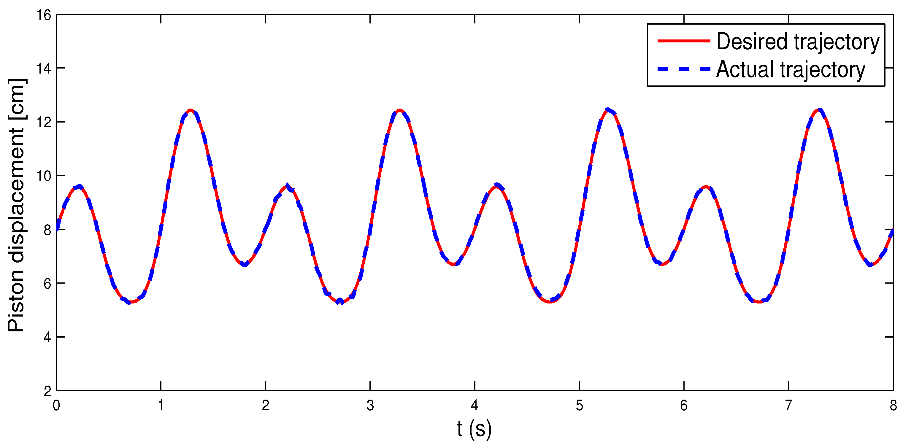
The validity of the proposed control strategy is confirmed through simulation studies in this part. The parameters of the exoskeleton mechanical system are shown in Table 1. The desired trajectory for rehabilitation is given as θ d = 43.2 cos ( π t ) / π + 64.8 sin ( 2 π t ) / π + 90 . Due to the fact that the state variable of the exoskeleton EHA (5) is the rod displacement, the geometric transformation (10) and (11) should be solved to acquire the desired rod displacement before implementing the controller. The geometric transformation is shown in Figure 3. Consequently, the control objective of the following simulation is to track the desired rod displacement y p d (the red curve).
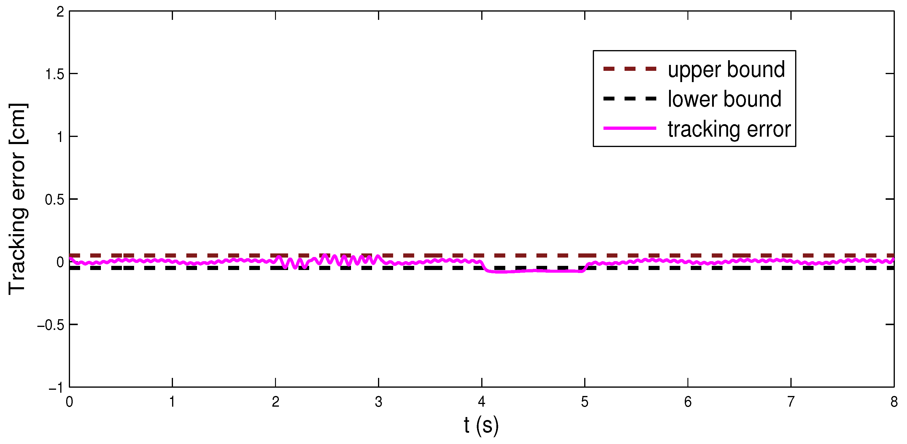
The external disturbance of the rehabilitation exoskeleton is given as f e ( t ) = 1.5 sin ( 2 π t ) + 0.5 cos ( π t ) + 2 , and the human–exoskeleton interaction is f h ( t ) = 2 sin ( 2 π t ) + 3 cos ( π t ) + 1.5 . The error constraint is set to k c = 0.05 . The unknown leakages of the EHA are
  Q l i ( t ) = 0.2 π sin ( 2.5 π t ) + 1.5 rand ( 1 ) ,   Δ l e 1 ( t ) = 1.2 sin ( 1.5 π t ) + 2 rand ( 1 ) ,   Δ l e 2 ( t ) = 2 cos ( π t ) + rand ( 1 ) .
The actuator fault is supposed to happen at t h = 2 and t δ = 4 with both enduring for 1 s. The healthy indicator and the bias faults are given as
h =   0.4 ,   2 t 3 ,   1 ,   0 < t < 2 , 3 < t . δ =   5 ,   4 t 5 ,   0 ,   0 < t < 4 , 5 < t .
To perform the proposed controller, a RBF-NN with 11 nodes is applied. The input of the NN is X = [ x 1 T , x 2 T , e 1 T , e 2 T , μ 2 ] . The network gain matrix is set to Ξ = diag [ 30 ] 11 x 11 with the initial weight Ψ ^ ( 0 ) = [ 0 ] 11 x 1 T . The control parameters are selected to k 1 = 60 , k 2 = 20 , k 3 = 1.5 , and k o = 20 . The initial value of the state is x = [ 8 , 0 , 0 ] . Responses of the proposed controller are shown in Figure 4, Figure 5 and Figure 6.
Figure 4 displays the curves of the desired rod displacement y p d and the actual rod displacement y p . It is clearly indicated that the trajectory tracking of the rod displacement is achieved by using the proposed control scheme. Figure 5 shows the tracking error and the bounds of the error constraint. The error constraint is not violated with the aid of the barrier Lyapunov function. Figure 6 shows the commanded controller and the actual controller. We can clearly see that the multiplicative fault happens at t = 2 and disappears at t = 3 , and the bias fault happens at t = 4 and disappears at t = 5 . These figures demonstrate that the control objective is reached by the proposed control scheme although the system is facing the difficulty of modeling uncertainties, unknown human–robot interaction, external disturbance, and actuator fault.
To further investigate the effectiveness of the controller, an additional comparative simulation which removes the fault-tolerant mechanism is carried out. The tracking response of the controller is shown in Figure 7. It seems that the displacement tracking is also achieved without the help of the fault-tolerant mechanism. However, from Figure 8, we can obtain that the tracking performance is degraded during 2 t 3 and even beyond the constraint bounds when 4 t 5 . This is because the controller cannot properly adjust its output when the actuator fault occurs.

5. Conclusions

This paper investigated the fault-tolerant trajectory tracking control for a rehabilitation exoskeleton with complex nonlinearities. The nonlinear uncertainties include the flow leakages of the EHA, the external disturbance, the human–exoskeleton interaction, the error constraint, and the actuator fault. The uncertainties of the exoskeleton system and the unknown disturbances are handled by neural networks and the nonlinear observer, respectively. Based on the barrier Lyapunov function, an adaptive fault-tolerant control strategy with guaranteed tracking performance is then proposed for improving the safety of the human–robot system. The comparative numerical simulations illustrate that the proposed control strategy has gratifying performance despite the actuator failure that takes place. Future work will include the investigation of the fault-tolerant control with actuator saturation.

Author Contributions

Methodology, C.S. and Y.Y.; Software, C.S.; Investigation, C.S.; Resources, Y.Y.; Data curation, Y.Y. All authors have read and agreed to the published version of the manuscript.

Funding

This work was supported in part by the National Natural Science Foundation of China under Grant 62003278 and in part by the Natural Science Foundation of Sichuan Province under Grant 2023NSFSC1431.

Conflicts of Interest

The authors declare no conflict of interest.

References

  1. Masengo, G.; Zhang, X.; Dong, R.; Alhassan, A.; Hamza, K.; Mudaheranwa, E. Lower limb exoskeleton robot and its cooperative control: A review, trends, and challenges for future research. Front. Neurorobot. 2023, 16, 913748. [Google Scholar] [CrossRef]
  2. Yang, J.; He, Y.; Shi, P.; Yu, H. A review on human intent understanding and compliance control strategies for lower limb exoskeletons. Proc. Inst. Mech. Eng. Part I—J. Syst. Control Eng. 2022, 236, 1067–1086. [Google Scholar] [CrossRef]
  3. Zhang, X.; Li, J.; Ovur, S.; Chen, Z.; Li, X.; Hu, Z.; Hu, Y. Novel design and adaptive fuzzy control of a lower-limb elderly rehabilitation. Electronics 2020, 9, 343. [Google Scholar] [CrossRef] [Green Version]
  4. Chen, C.; Lien, W.; Chen, C.; Twu, M.; Wu, Y. Dynamic modeling and motion control of a cable-driven robotic exoskeleton with pneumatic artificial muscle actuators. IEEE Access 2020, 8, 149796–149807. [Google Scholar] [CrossRef]
  5. Pehlivan, A.; Losey, D.; O’Malley, M. Minimal assist-as-needed controller for upper limb robotic rehabilitation. IEEE Trans. Robot. 2015, 32, 113–124. [Google Scholar] [CrossRef]
  6. Martinez-Peon, D.; Olguín-Díaz, E.; Munoz-Vázquez, A.; Francisco, P.; Méndez, D. Modeling and control of exoskeleton for wrist and forearm rehabilitation. Biomed. Signal Process. Control 2021, 70, 103022. [Google Scholar] [CrossRef]
  7. Wu, Q.; Chen, B.; Wu, H. Neural-network-enhanced torque estimation control of a soft wearable exoskeleton for elbow assistance. Mechatronics 2019, 63, 102279. [Google Scholar] [CrossRef]
  8. Milecki, A.; Nowak, P. Review of Fault-Tolerant Control Systems Used in Robotic Manipulators. Appl. Sci. 2023, 13, 2675. [Google Scholar] [CrossRef]
  9. Shi, P.; Wang, X.; Meng, X.; He, M.; Mao, Y.; Wang, Z. Adaptive fault-tolerant control for open-circuit faults in dual three-phase pmsm drives. IEEE Trans. Power Electron. 2022, 38, 3676–3688. [Google Scholar] [CrossRef]
  10. Zhang, X.; Zhou, Z. Integrated fault estimation and fault tolerant attitude control for rigid spacecraft with multiple actuator faults and saturation. IET Contr. Theory Appl. 2019, 13, 2365–2375. [Google Scholar] [CrossRef]
  11. Wang, Z.; Wang, G. Temperature fault-tolerant control system of CSTR with coil and jacket heat exchanger based on dual control and fault diagnosis. J. Cent. South Univ. 2017, 24, 655–664. [Google Scholar] [CrossRef]
  12. Liu, C.; Jiang, B.; Zhang, K.; Ding, S. Hierarchical structure-based fault-tolerant tracking control of multiple 3-DOF laboratory helicopters. IEEE Trans. Syst. Man Cybern. Syst. 2021, 52, 4247–4258. [Google Scholar] [CrossRef]
  13. Ren, Y.; Fang, Y.; Wang, A.; Zhang, H.; Wang, H. Collaborative operational fault tolerant control for stochastic distribution control system. Automatica 2018, 98, 141–149. [Google Scholar] [CrossRef]
  14. Amin, A.; Hasan, K. A review of fault tolerant control systems: Advancements and applications. Measurement 2019, 143, 58–68. [Google Scholar] [CrossRef]
  15. Tee, K.; Ge, S.; Tay, E. Barrier Lyapunov functions for the control of output-constrained nonlinear systems. Automatica 2009, 45, 918–927. [Google Scholar]
  16. Ding, S.; Zhang, B.; Mei, K.; Park, J. Adaptive fuzzy sosm controller design with output constraints. IEEE Trans. Fuzzy Syst. 2021, 30, 2300–2311. [Google Scholar] [CrossRef]
  17. Sun, W.; Lan, J.; Yeow, J. Constraint adaptive output regulation of output feedback systems with application to electrostatic torsional micromirror. Int. J. Robust Nonlinear Control 2015, 25, 504–520. [Google Scholar] [CrossRef]
  18. Zhao, Z.; He, W.; Ge, S. Adaptive neural network control of a fully actuated marine surface vessel with multiple output constraints. IEEE Trans. Control Syst. Technol. 2013, 22, 1536–1543. [Google Scholar]
  19. Hu, H.; Cao, J. Practical tracking control for dual-arm robot with output constraints. Int. J. Control Autom. Syst. 2022, 20, 3264–3273. [Google Scholar]
  20. Liu, Y.; Lu, S.; Tong, S. Neural network controller design for an uncertain robot with time-varying output constraint. IEEE Trans. Syst. Man Cybern. Syst. 2017, 47, 2060–2068. [Google Scholar] [CrossRef]
  21. Jin, L.; Li, S.; Hu, B.; Liu, M. A survey on projection neural networks and their applications. Appl. Soft. Comput. 2019, 76, 533–544. [Google Scholar] [CrossRef]
  22. Li, Y.; Zhang, J.; Xu, X.; Chin, C. Adaptive fixed-time neural network tracking control of nonlinear interconnected systems. Entropy 2021, 23, 1152. [Google Scholar] [CrossRef] [PubMed]
  23. Fei, J.; Chen, Y.; Liu, L.; Fang, Y. Fuzzy multiple hidden layer recurrent neural control of nonlinear system using terminal sliding-mode controller. IEEE Trans. Cybern. 2021, 52, 9519–9534. [Google Scholar] [CrossRef] [PubMed]
  24. Li, M.; Li, S.; Zhang, J.; Wu, F.; Zhang, T. Neural adaptive funnel dynamic surface control with disturbance-observer for the pmsm with time delays. Entropy 2022, 24, 1028. [Google Scholar] [CrossRef]
  25. Sun, X. Kinematics model identification and motion control of robot based on fast learning neural network. J. Ambient Intell. Humaniz. Comput. 2021, 11, 6145–6154. [Google Scholar] [CrossRef]
  26. Chen, J.; Huang, J. Application of adaptive observer to sensorless induction motor via parameter-dependent transformation. IEEE Trans. Control Syst. Technol. 2018, 27, 2630–2637. [Google Scholar] [CrossRef]
  27. Cai, H.; Huang, J. Output based adaptive distributed output observer for leader–follower multiagent systems. Automatica 2021, 125, 109413. [Google Scholar] [CrossRef]
  28. Wei, X.; Chen, N.; Li, W. Composite adaptive disturbance observer-based control for a class of nonlinear systems with multisource disturbance. Int. J. Adapt. Control Signal Process. 2013, 27, 199–208. [Google Scholar] [CrossRef]
  29. Li, X.; Wei, X.; Zhang, H.; Han, J.; Hu, X.; Liu, X. Adaptive nonlinear disturbance observer-based control for stochastic systems with multiple heterogeneous disturbances. Trans. Inst. Meas. Control 2020, 42, 2020–2030. [Google Scholar] [CrossRef]
  30. Yang, Y.; Li, Y.; Liu, X.; Huang, D. Adaptive neural network control for a hydraulic knee exoskeleton with valve deadband and output constraint based on nonlinear disturbance observer. Neurocomputing 2022, 473, 14–23. [Google Scholar] [CrossRef]
  31. Jiang, C.; Sui, S.; Tong, S. Finite-time fuzzy adaptive output feedback control of electro-hydraulic system with actuator faults. Inf. Sci. 2023, 623, 577–591. [Google Scholar] [CrossRef]
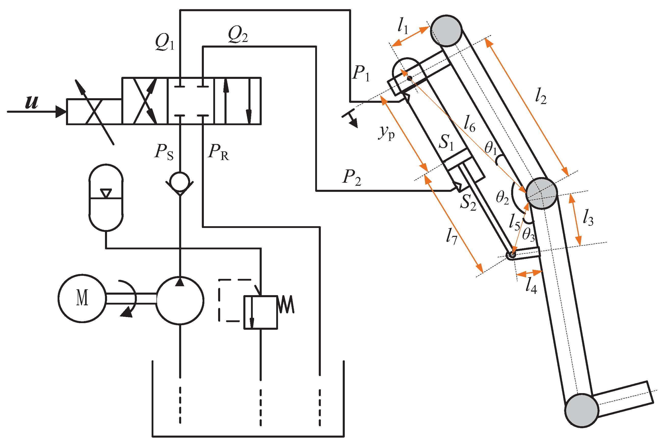
Figure 1. Rehabilitation exoskeleton joint with EHA.
Applsci 13 08294 g001
Figure 2. The proposed control structure.
Applsci 13 08294 g002
Figure 3. Curves of the geometric transformation.
Applsci 13 08294 g003
Figure 4. Curves of the displacement tracking.
Applsci 13 08294 g004
Figure 5. Curves of the tracking error.
Applsci 13 08294 g005
Figure 6. The commanded controller and actual controller.
Applsci 13 08294 g006
Figure 7. Curves of the displacement tracking without FTC.
Applsci 13 08294 g007
Figure 8. Curves of the tracking error without FTC.
Applsci 13 08294 g008
Table 1. The parameters of the exoskeleton mechanical system.
DescriptionSymbolValue
l 1 Mechanical length 1 6   cm
l 2 Mechanical length 2 26   cm
l 3 Mechanical length 3 7   cm
l 4 Mechanical length 4 5   cm
l 7 Mechanical length 7 13   cm
mEquivalent load acted on the piston rod 15   kg
cCombined friction coefficient950
S 1 The piston area of the non-rod chamber 7   cm 2
S 2 The piston area of the rod chamber 3   cm 2
β e Effective bulk modulus 9 × 10 4   N / cm 2
ρ The areas ratio S 1 / S 2
k s The valve flow/signal gain 0.95
V 1 Initial volume of the non-rod chamber 85   cm 3
V 1 Initial volume of the rod chamber 6.5   cm 3
Disclaimer/Publisher’s Note: The statements, opinions and data contained in all publications are solely those of the individual author(s) and contributor(s) and not of MDPI and/or the editor(s). MDPI and/or the editor(s) disclaim responsibility for any injury to people or property resulting from any ideas, methods, instructions or products referred to in the content.