Abstract
This paper introduces a new type of uplift pile known as the composite-anchor pile, which employs a composite anchor composed of steel strands, grouting materials, and steel pipes as the main reinforcement. This paper extensively analyzes this pile’s load-bearing capacity and deformation characteristics through full-scale field tests and three-dimensional finite element numerical simulations. The results show that the composite-anchor pile has a more even distribution of stress, and its endurance and mechanics performance are better than others. Furthermore, this study utilizes a three-dimensional finite element refined model that has been validated using on-site test results to examine the influence of key parameters, such as the pile diameter, the number of composite-anchor cables, and the diameter of steel strands, on the load-bearing capacity of uplift piles. Building upon these findings, this paper introduces a calculating method to determine the bearing capacity of composite-anchor piles, thereby addressing the existing gap in this field.
1. Introduction
Currently, the issue of preventing the flotation of large raft-like structures is typically addressed through the use of anti-floating piles [1]. However, traditional reinforced concrete anti-floating piles possess two drawbacks. Firstly, while the concrete protective layer provides some level of protection to the reinforcement, it is susceptible to cracking under the tensile stress that the anti-pulling pile endures. This phenomenon is particularly prevalent in areas with high groundwater levels, especially in environments characterized by alternating wet and dry conditions. The cracking of the concrete in the pile can lead to the corrosion of the reinforcement, especially in coastal regions where the groundwater is frequently laden with chloride and sulfate ions. The highly corrosive nature of these ions can cause the internal reinforcement of the anti-pulling pile to rust, thereby undermining its load-bearing capacity and overall performance in service [2]. Secondly, to mitigate the aforementioned problem, it is common practice to increase the amount of reinforcement. However, an excessively high reinforcement ratio can hinder the load-bearing capacity and extensibility of the primary reinforcement, resulting in the unnecessary wastage of steel and escalated costs [3,4]. Consequently, ongoing research endeavors are primarily focused on reducing reinforcement wastage in corrosive environments, while concurrently enhancing the longevity and safety of anti-floating piles.
Numerous studies have been conducted by researchers to enhance the uplift bearing capacity of pile foundations. These studies encompass the exploration of novel technologies [5] and innovative types of piles [6]. Additionally, researchers have extensively investigated various aspects of new uplift piles, such as their bearing characteristics [7,8], lateral stresses between piles and soil, load transfer mechanisms, and other factors pertaining to conventional uplift piles. Scholars frequently employ field tests [9,10], model tests [11], finite element simulations [12,13,14], and numerical solutions to address scientific challenges.
For example, Yu et al. [15] utilized a comprehensive methodology, combining field experiments and finite element simulations, to elucidate the load-bearing behavior of bored piles. Their investigation encompassed the analysis of axial forces, load–displacement curves, and load distribution across different components, aiming to discern the load transfer mechanism specific to this pile type. Levacher [16] performed three series of pile uplift tests, comprising driven piles, vibrated piles, and bored piles. The test results led them to propose the utilization of a coefficient to evaluate the influence of pile installation methods on the pile’s bearing capacity. He et al. [17] compared the load-carrying capacity of bottom-uplift piles and anchor piles in their study, based on load tests on foundation piles. They found that bottom-uplift piles had double the peak load-carrying capacity of conventional uplift piles. Additionally, the pile diameter had a greater impact on the load-carrying capacity than the pile length or elastic modulus. Ilamparuthi et al. [18] investigated a method to improve the uplift resistance of deep-foundation piles by reinforcing the soil mass surrounding the expansion head. They developed a theoretical framework that established a nonlinear quadratic relationship between the uplift force and displacement of deep foundation piles, and derived an associated formula for calculating the bearing capacity. In a separate study, Goel et al. [19] examined the reduction in load on piles during uplift through the development of a numerical simulation program. The results demonstrated that the resistance on the pile side increases proportionally with the relative displacement between the pile and the soil.
The methods used in the above study are of guiding significance for the development and performance analysis of composite-anchor piles. Mao et al. [20] conducted in-depth research of the innovative composite-anchor pile that integrates an internal composite anchoring system comprising three key components: steel strands, high-strength steel pipes, and grout. By utilizing a combination of on-site tests and numerical simulations, they examined the load-carrying mechanism and bearing performance of these newly developed uplift piles.
However, a notable limitation exists as there is a lack of a well-defined design method for determining the bearing capacity of these composite-anchor piles, which poses a hindrance to their practical implementation in engineering projects [20]. To address this gap, this study aims to evaluate the influence of crucial parameters, such as the pile diameter, the number of composite-anchor cables, and the steel strand diameter, on the load-bearing capacity of uplift piles. This assessment will be based on a three-dimensional finite element refined model that has been validated against on-site test results. Moreover, this paper proposes a straightforward and pragmatic calculation method grounded in current standards, ultimately providing theoretical support for the practical application of composite-anchor uplift piles in engineering projects [21,22]. The composite-anchor cable structure incorporated within the pile enables the adaptability of the composite-anchor pile to diverse working conditions, rendering it a promising solution to revolutionize the current utilization of uplift piles. This innovation, for instance, mitigates steel reinforcement wastage and improves the longevity of uplift piles in corrosive environments.
2. Field Testing on Uplift Capacity in Composite-Anchor Cable Uplift Pile
This study involved conducting multiple sets of field tests on three different types of test piles. The primary objectives of these tests were to assess the effectiveness of composite-anchor piles, investigate the impact of different hole-forming methods, and compare the bearing performance of these piles with that of traditional piles. The field tests were carried out in the Tongzhou District, Beijing, at a site elevation of 24.00 m. The pile foundation construction face elevation was 21.00 m, while the top elevation of the test piles was 19.50 m, with a 1.50 m protective layer for the piles. The soil layer at the site predominantly consisted of sandy and silty soil, with a uniform and consistent distribution of soil quality to ensure that the test results were not influenced by variations in soil quality. Specific stratigraphic diagrams and key physical and mechanical parameters of the site can be found in reference [20]. The field test process and analysis of the results are presented below.
2.1. Static Load Test on Site
This experiment consists of three different groups of test piles, with each group being tested multiple times and the results averaged. The relevant details of the experiment are provided in Table 1 [20]. The Type-A test pile is classified as a conventional pile, while the Type-B and Type-C test piles are categorized as composite-anchor cable uplift piles. Two different hole-forming methods were employed for the three groups of test piles. The static load test for each individual pile followed the applicable technical specifications outlined in the Technical Code for the Testing of Building Foundation Piles (JGJ 106-2019) [23] and the Technical Code for Building Pile Foundations (JGJ 94-2008) [24]. Hydraulic jacks were used to apply the load, and displacement sensors were utilized to measure the displacement of the pile top. The objective was to generate real-time load–displacement curves.

Table 1.
Information on the three types of test piles [20].
The field test consists of three main steps: loading, terminating loading, and unloading. During the loading phase, the test pull-out force is applied gradually in stages using an equal load approach. According to the test protocol, each stage load is set at 10% of the ultimate bearing capacity calculation value, with the first stage load set at 20%. After each stage of load application, the displacement of the pile top is automatically recorded at specific time intervals, including at 5, 15, 30, 45, and 60 min, and then every 30 min thereafter. Loading continues once the displacement change rate is ≤0.1 mm/h and occurs twice in a row, indicating relative stability has been achieved. The loading should be terminated under the following conditions: (1) If the applied load or deformation value meets the design acceptance requirements. (2) If the stress in the tensioned strands of the reaction device or composite-anchor cable reaches the design value of the strand, including strand fracture. (3) If the displacement value of the pile top in the last stage of load exceeds five times that of the previous stage. (4) If the cumulative displacement value of the pile top exceeds 100 mm [24]. The unloading phase is carried out in stages, with each stage of unloading being twice the load of the corresponding loading stage. The unloading is performed evenly and equally. After each stage of unloading, the pile remains under the load for 1 h, and the displacement is measured three times at 15, 30, and 60 min. Following complete unloading, the pile remains under the load for an additional 3 h, and displacement is measured three times at 15, 30, 60, 90, 120, 150, and 180 min [25]. Upon completion of the test, the displacement acquisition system and pull-out force application system are sequentially and slowly removed.
2.2. Results of Load Tests on Site
Figure 1 illustrates the displacement curve of the pile top under uplifting loads for the three sets of test piles. In this depiction, the variable U signifies the pile-top load, while δ represents the pile-top uplifting displacement. The load–displacement curve of the Type-A test pile displays a steep profile, while those of the Type-B and Type-C test piles exhibit gentler characteristics. During the initial loading phase, the Type-A pile’s top displacement increases nearly linearly with the growing uplifting load. However, as the uplifting load surpasses 6160 kN, the uplifting displacement experiences a sudden change, marking a distinct turning point. As per the Technical Code for the Testing of Building Foundation Piles (JGJ 106-2019) [23], this turning point designates the onset of a significant increase in the single pile’s ultimate carrying capacity for the Type-A pile. In contrast, the vertical displacement of the pile tops for the Type-B and Type-C piles exhibits consistent and gradual increases at each loading level, devoid of abrupt variations. According to the specifications, the determination of the ultimate bearing capacity for each test pile should be based on the load value at the preceding level where the δ-lgt curve’s slope exhibits a notable increase or the curve’s tail displays a significant bend. Therefore, the ultimate load results of the static load test for each pile are shown in Table 2. It is important to note that the alteration in the measurement method for displacement only impacts the displacement data of the composite-anchor piles. Consequently, the displacement data for Type-A remains unchanged from previous articles, while the displacement data for Type-B and Type-C are derived from this experiment.
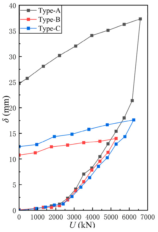
Figure 1.
Load–displacement curve of three test piles.
Table 2.
Results of static load test on single pile.
An in-depth analysis of the U-δ curves shows similar initial uplift displacements among the different pile types. However, as the applied load increases, the displacement of the new piles (Type-B and Type-C) gradually exceeds that of the conventional pile (Type-A). Comparing the Type-A and Type-B piles, the uplift bearing capacity of the Type-A piles is approximately 16.7% higher. It is important to note that both Type-A and Type-B piles surpass the estimated bearing capacity of 4400 kN, meeting the design requirements for the uplift bearing capacity. On the other hand, comparing the Type-B and Type-C piles reveals that Type-C piles have an approximately 18.2% higher bearing capacity than Type-B piles. This significant difference can be attributed to the use of the dry rotary drilling method for hole formation in Type-C piles, which prevents the formation of a mud skin between the pile body and the surrounding foundation soil, thereby improving stress conditions and reducing deformation. Furthermore, the uplift bearing capacity of Type-C piles increases by approximately 1.3% compared to Type-A piles.
3. Numerical Simulation of Uplift Capacity in Composite-Anchor Piles
In this section, the modeling process for the numerical simulation is described, followed by an analysis of the computational results. The objective is to investigate the impact of factors such as the pile diameter, the quantity of composite-anchor cables, and the diameter of steel strands on the pull-out bearing capacity of composite-anchor piles. The aim is to gain insights that can inform future designs for the bearing capacity of these piles.
3.1. Numerical Simulation Based on Finite Element Method
Based on previous research findings, it has been determined that the influence range of composite-anchor piles on the surrounding soil during vertical uplift bearing capacity tests is approximately twice the pile diameter. The load at the top of the pile has negligible effects on the deformation and stress of the soil beyond this range. Therefore, in order to minimize the number of elements and simplify the computational process, the finite element model was created by extending the pile body 20 times the pile diameter outward. ABAQUS 2020 software was used for modeling, and Figure 2 illustrates the three-dimensional numerical model of the composite-anchor pile. The modeling depth was set at 30 m, with an extension of 8 m below the pile base. The three-dimensional finite element model represents a cylinder with a diameter of 16 m and a height of 30 m. The uplift pile has a diameter of 0.8 m and a height of 22.0 m, located at the center of the model. The composite-anchor cable within the uplift pile consists of steel strands, grout, and steel pipes, each with a length of 22.0 m. These elements are distributed around the pile body, with a concrete protective layer thickness of 70 mm, in accordance with the actual field conditions. A detailed modeling approach was employed based on the structural characteristics of the composite-anchor pile. The model comprises a total of 78,716 elements, with 41,180 elements specifically dedicated to simulating the uplift pile. To accurately represent the structural design while ensuring mesh convergence [26,27], the internal composite-anchor cable was subdivided into 34,020 elements, accounting for approximately 82.6% of the overall uplift pile model. After establishing the solid model, vertical and lateral displacement constraints were applied at the bottom of the model, normal horizontal constraints were imposed around the model, and gravity load was applied.
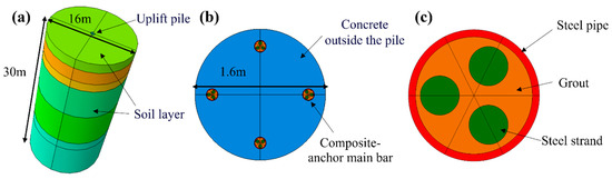
Figure 2.
Three-dimensional numerical model: (a) overall model; (b) cross-section of uplift pile; (c) section of main reinforcement of composite-anchor cable [20].
During the modeling process, the material property parameters are chosen based on the actual parameters of the materials used in the field load tests. These parameter values align with the experimental study mentioned in reference [22] and can be found in Table 3 and Table 4 of the study. By utilizing these specific material property parameters, the model can more accurately replicate the behavior of the composite piles observed in the experimental study.
Table 3.
Physical parameters of the soil layers [20].
Table 4.
Physical parameters of the composite-anchor uplift pile [20].
In the analysis of the bearing capacity of composite piles, several parameters were selected for investigation. Firstly, four different pile sizes were chosen, namely 800 mm, 900 mm, 1100 mm, and 1200 mm. These sizes are commonly used in large-diameter pile foundation projects and are suitable for various soil types and load requirements. The selection of pile size in civil engineering depends on factors such as soil properties, load requirements, and specific project conditions. By considering these common pile sizes, the research results can be more widely applicable to different engineering scenarios. Secondly, the number of anchor cables was considered as an important parameter affecting the bearing capacity and stability of composite piles. In practical engineering, the selection of the number of anchor cables is based on design requirements, soil conditions, seismic requirements, and other factors. In the field load tests, four anchor cables were chosen as the primary configuration, and additional configurations with three and five anchor cables were included as control groups. This allows for a broader range of working conditions to be studied and analyzed. Lastly, the diameter of the steel strand was investigated as another significant factor influencing the bearing capacity and stability of the pile. Different diameters of steel strands exhibit different strength and stiffness characteristics, which directly impact the pile’s bearing capacity. Two common diameters, namely 21.8 mm and 15.2 mm, were selected for the study. These diameters are widely used in practical engineering projects and can cover most scenarios. By examining these two common steel strand diameters, a better understanding of the influence of the diameter on the bearing capacity of composite piles can be obtained.
Furthermore, the interface between different components within composite-anchor piles plays a crucial role in influencing their behavior. Thus, during the creation of the model, distinct contact surfaces are established for steel strands, grout materials, steel pipes, and pile concrete. To define these contact surfaces and solid element parameters, relevant information from previous research is utilized. The Coulomb shear model is employed to simulate the contact effect, with penalty functions utilized to incorporate tangential behavior. The friction coefficient is determined based on empirical formulas sourced from the existing literature [28]. Moreover, throughout the simulation process, it is assumed that only tangential relative slip occurs once the pile–soil contact is established.
Once the physical model is created, vertical and horizontal displacement constraints are applied at the bottom of the model, while normal horizontal constraints are established around the model. A gravity load is then applied to replicate the in situ stress conditions. Next, the displacements of the entire model are set to zero, and the vertical load is incrementally applied at the top of the pile. The incremental loading process mimics the field load testing procedure to ensure accuracy in the simulation results. This approach helps avoid potential errors that may arise from loading inconsistencies and enables a more precise analysis of the pile’s behavior under different loading conditions. By following a loading process similar to the field load testing process [20], the simulation results can better reflect the real-world conditions and provide more reliable insights into the performance of the composite pile.
3.2. Parameter Study Results Based on Finite Element Method
Figure 3 displays the load–displacement curves of the C-shaped pile obtained through both numerical simulation and field static load testing. The simulated and experimental results show a difference of approximately 0.57 mm in the pile head displacement at the maximum ultimate load, indicating an error of about 3.1%. A comparative analysis of the results indicates that, on the one hand, the model is reliable and suitable for future studies. On the other hand, considering the actual soil conditions, the analysis suggests that the discrepancy may be attributed to the incomplete uniformity and complexity of the soil layers.
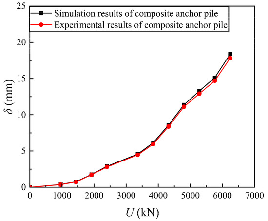
Figure 3.
Comparison of load–displacement curves from numerical simulations and field load tests.
Figure 4 shows the simulation results of Type-B piles at load levels 1, 5, 9, and 11. Generally speaking, the vertical displacement of the lifting pile and the surrounding soil will be higher as the load is increased. At a depth of 1.5–2 times that of the pile base, there is no influence on the displacement of the surrounding earth.
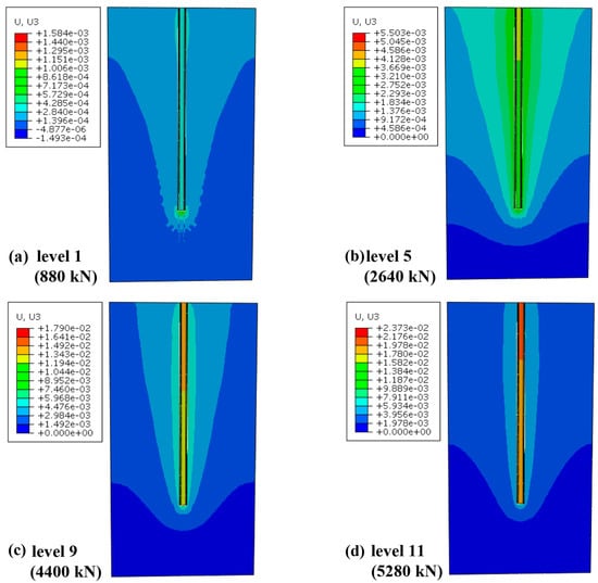
Figure 4.
Vertical displacement distribution of soil layers under different load levels: (a) level 1: 880 kN; (b) level 5: 2640 kN; (c) level 9: 4400 kN; (d) level 11: 5280 kN.
With the increase in the load, the displacement of the soil around the pile increases gradually, but tends to be the same gradually, which shows that in the early stage of uplift, the side resistance of the pile is smaller, the soil layer moves up with the pile, and the slope of the curve is lower. During the process of uplift, the side friction of the pile increases, exceeding the frictional resistance at the pile–soil interface. This results in a significant relative displacement between the pile and the soil, reducing the influence of the pile on the surrounding soil displacement. At this stage, the slope of the curve is larger. Therefore, the load displacement curve in Figure 3 is nonlinear. Additionally, it is crucial to note that the pile shaft and the surrounding foundation undergo coordinated deformation. The displacement at the interface between the two remains consistent, indicating that the pile–soil interface has not been damaged.
The composite-anchor uplift pile falls into the category of friction piles, and pile-side frictional resistance plays a predominant role in providing support. The extent of this frictional resistance is determined by the dimensions of the interface between the pile and the surrounding soil.
Figure 5 illustrates the load–displacement curves of Type-C for various pile diameters. Upon scrutinizing the figure, it is evident that augmenting the pile diameter from 800 mm to 1200 mm yields a 26% increase in the bearing capacity of the composite-anchor pile. However, when evaluating each 100 mm increment in the pile diameter individually, the uplift pile’s bearing capacity merely elevates by 11% when the diameter reaches 900 mm. Additionally, as the pile diameter continues to increase, the rate of improvement in the uplift pile’s bearing capacity diminishes. This implies that while expanding the pile diameter enhances the bearing capacity to a certain extent, there are limitations to its growth rate.
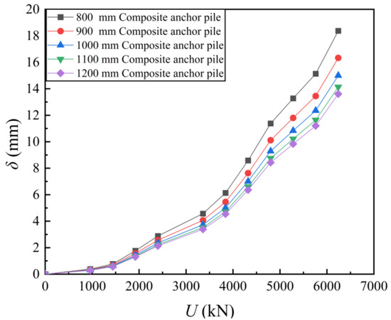
Figure 5.
Load–displacement curves with different pile diameters.
The rationale behind this observation may be attributed to the fact that an 800 mm-diameter pile already falls within the realm of large diameter uplift piles. Consequently, increasing the pile diameter without adjusting the pile length hampers the ability to transfer the load at the pile tip to deeper soil, thereby restricting any substantial enhancement in the pile’s bearing capacity. Furthermore, increasing the pile diameter can lead to higher manufacturing and installation costs. Moreover, employing multiple smaller diameter piles may be more cost-effective than employing a single larger diameter pile. The combined bearing capacity of multiple smaller diameter piles can be equivalent to or even greater than that of a single larger diameter pile, while the overall cost may be lower. Particularly when considering the logistics and transportation of materials, smaller diameter piles are more manageable and easier to transport. Therefore, a thorough assessment of site conditions, load requirements, and cost implications is necessary to make an informed decision regarding the pile diameter.
The composite-anchor cable is the main reinforcement structure of the composite-anchor pile. To assist construction professionals in selecting suitable uplift pile configurations based on varying real-world project conditions, finite element simulations were conducted using three, four, and five composite-anchor cables. Figure 6 illustrates the changing trend of the pile top load–displacement curve in the three sets of simulations. It is evident from the figure that when comparing three composite-anchor cables to four composite-anchor cables, the pile top displacement decreases by 2 mm, and the bearing capacity increases by 10%. However, if the number of anchor cables is further increased to five, the pile top displacement only decreases by an additional 0.5 mm, and the bearing capacity only increases by 2%. In general, under these conditions, increasing the number of anchor cables effectively enhances the bearing capacity of the composite-anchor pile when the number of cables is less than four. However, when the number of anchor cables is four or more, having too many cables can lead to a wasted partial bearing capacity and increased cost burden. Furthermore, the composite-anchor pile is a more intricate structural component compared to the overall foundation, and having an excessive number of anchor cables may increase manufacturing difficulty and labor costs. Additionally, the fixed cross-section of the pile results in a higher reinforcement ratio when the number of cables is increased, which can lead to brittle failure under extreme loading conditions and compromise the overall stability of the structure. Therefore, conducting a comprehensive analysis and cost-benefit assessment to determine the optimal number of anchor cables for a specific project is crucial.
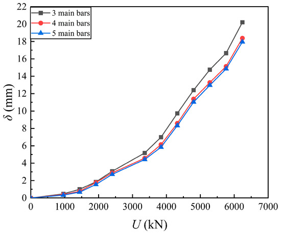
Figure 6.
Load–displacement curves with different quantities of main bars.
The primary load-bearing component in the composite-anchor pile under investigation is the steel strand. The larger the diameter of the steel strand, the larger its cross-sectional area, resulting in lower section pressure under the same uplift load. With the material strength of the steel strand guaranteed, larger-diameter strands are less prone to deformation and can withstand higher uplift loads. Consequently, composite-anchor piles using larger-diameter steel strands experience smaller displacements at the pile top. But to optimize the structural design of composite-anchor piles, calculations were performed using two commonly used steel strand diameters: 15.2 mm and 21.8 mm.
Figure 7 illustrates the numerical results of Type-C for varying strand diameters. The figure reveals that the bearing capacities of the pile with the two different steel strand diameters are comparable when the load is below level 6. Moreover, the displacement difference at the pile top during this stage is minimal, ranging from 0 to 1 mm. However, as the load progresses, the displacement difference between the two diameter steel strands at the pile top increases to a range of 1.5 to 3.0 mm. Therefore, in practical applications, trade-offs need to be made based on the structural load-bearing capacity. When the load conditions exceed 3840 kN, larger-diameter steel strands should be chosen. However, larger-diameter steel strands are usually more expensive and may impact the project’s cost. Additionally, the installation of larger-diameter steel strands is more challenging and requires specialized equipment, which may increase labor costs and construction time. Therefore, when the load-bearing capacity requirements of the project are relatively low, smaller-diameter steel strands should be used. Smaller-diameter steel strands are easier to handle and install, and they also provide higher flexibility, making them suitable for seismic engineering. Based on these considerations, it is recommended to carefully evaluate the specific requirements of the project when selecting the diameter of the steel strands.
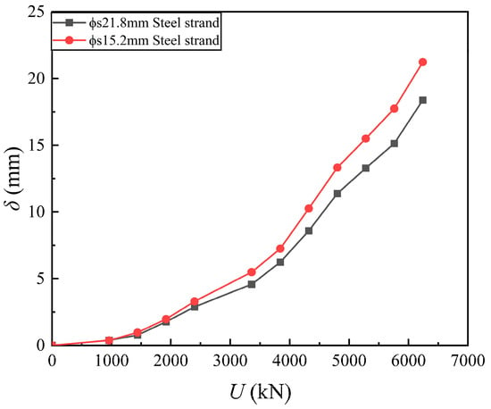
Figure 7.
Load–displacement curves with different diameters of steel strands.
4. Design Methodology of Composite-Anchor Uplift Piles
Previous research has demonstrated the enhanced load-bearing capacity and deformation resistance of composite-anchor piles compared to traditional piles. Additionally, composite-anchor piles exhibit substantial improvements in corrosion resistance, economic performance, and bottom plate waterproofing capabilities. These advantages align with the design objectives of achieving low reinforcement ratios and high bearing capacities. Composite-anchor piles can be directly substituted for traditional piles and are particularly suitable for projects with strict time constraints. This study serves as a valuable demonstration for the future adoption and promotion of composite-anchor piles. To facilitate their application and promotion, it is essential to investigate their design methodologies.
In the design process for determining the bearing capacity of uplift piles, traditional friction uplift piles only require verification of conditions where the pile’s bearing capacity is governed by the soil’s frictional resistance on the pile side. However, composite-anchor piles possess a unique composite-anchor cable structure. Through previous experiments and numerical simulations on factors influencing the bearing capacity, it has been established that the calculation of uplift bearing capacity for composite-anchor piles must consider the interface frictional resistance within the composite-anchor cable inside the pile. Consequently, a formula is proposed in this study to calculate the bearing capacity of uplift piles controlled by the interface frictional resistance of the composite-anchor cable inside the pile. Moreover, based on numerical simulation results, parameters such as the number of anchor cables are integrated into the formula design process. Furthermore, previous research findings indicate that composite-anchor piles exhibit superior bearing characteristics compared to conventional piles of the same size. Consequently, the dimension design of the pile shaft can be based on conventional piles, ensuring conservative results that contribute significantly to the safety and deformation control of the structure. Considering these factors, this paper recommends utilizing conventional pile design methods when determining the number and dimensions of composite-anchor piles. The design characteristic value of the bearing capacity of composite-anchor piles can be initially estimated by summing the ultimate lateral frictional resistance of each soil layer. The specific formula design process is outlined as follows.
4.1. Ultimate Bearing Capacity with Surrounding Soil Failure
When the uplift pile’s bearing capacity is controlled by the failure of the surrounding soil, the calculation of bearing capacity should meet the following requirements:
For the pile group with block failure:
For the pile group with non-block failure:
where Nk is standard value of tension force on single pile (kN); T is characteristic value of uplift bearing capacity of single pile (kN); Tgk is calculated value of the ultimate bearing capacity of single pile when the non-block failure occurs, which can be determined by Formula (5); Tuk is calculated value of the ultimate bearing capacity of single pile when block failure occurs, which can be determined by Formula (4); Ggp is equivalent pile–soil weight of single pile when the pile group undergoes block failure; and Gp is weight of single pile when the pile group undergoes non-block failure.
The ultimate uplift bearing capacity of a single pile in the preliminary design phase can be estimated as follows.
(1) For pile groups with non-block failure, the single pile’s ultimate bearing capacity can be calculated by
where ui is perimeter of pile (m); λip is uplift coefficient of the i-th layer of rock (or soil), which can be taken from Table 5 and should be determined in combination with the results of on-site static load tests; and qsik is standard value of the ultimate lateral resistance of the i-th layer of rock (or soil) on the pile-side surface (kPa), which should be determined through on-site tests or local experience. During preliminary design, this can be determined using the empirical parameter method outlined in the current standard “Technical Code for Building Pile Foundations” (JGJ 94-2008), where li is pile length in the i-th layer of rock (or soil) (m).
Table 5.
Suggested values of pull-out coefficient .
(2) When the pile group experiences block failure [24], the single pile’s ultimate bearing capacity can be calculated by
where ul is the perimeter of outer boundary of the pile group (m).
(3) The tensile bearing capacity of the pile’s normal section shall comply with the following formula [29],
where N is design value of axial tension at the pile top under basic load effect combinations; fy, fpy are design values of tensile strength for steel bars and steel strands, respectively; and As, Apy are cross-sectional areas of ordinary steel bars and steel strands, respectively.
4.2. Ultimate Bearing Capacity with Composite Anchor Interface Failure
When evaluating the uplift pile’s bearing capacity, it is imperative to account for potential frictional resistance failures at multiple interfaces, including those between the steel strand and cement grout, the interface between the cement grout and the inner wall of the steel pipe, and the interface between the outer wall of the steel pipe and the concrete of the pile body. The bearing capacity must strictly adhere to the following criteria:
where Qck denotes the minimum frictional resistance at the interfaces within the pile. As there are three distinct interfaces, specifically the steel strand–grouting body interface, the grouting body–steel pipe interface, and the steel pipe–pile concrete interface, the frictional resistance for the three interfaces can be calculated, respectively, as follows.
(1) Friction resistance at the steel strand–cement grout interface:
where n is quantity of composite-anchor cables in the pile and d1 is equivalent diameter of the steel strands. When using a single steel strand as reinforcement, take the single steel strand’s diameter; when using multiple steel strands as reinforcement, take the equivalent diameter. The equivalent diameter can be determined in accordance with the requirements in Section 7.1.2 of “Code for Design of Concrete Structures”, where τ1 is the ultimate bond strength between the steel strand and the grout, determined experimentally or following the recommended values in the specifications, typically ranging from 2.0 to 3.0 MPa. A higher value is selected when the grout has higher strength and good construction quality, and a lower value is chosen otherwise. Here, l1 is the bond length of steel strands within the grout.
(2) Friction resistance at the grout–steel pipe interface:
where n is quantity of composite-anchor cables in the pile; d2 is inner diameter of high-strength steel pipe; and τ2 is the ultimate bond strength between the cement grout and the inner wall of the steel pipe, which should be determined experimentally or following the recommended values in the specifications, typically ranging from 2.0 to 3.0 MPa. A higher value is selected when the grout has higher strength and good construction quality, and a lower value is chosen otherwise. Here, l2 is the bonding length between the cement grout and the inner wall of the steel pipe.
(3) Friction resistance at the steel pipe outer wall–pile concrete interface:
where n is quantity of composite-anchor cables in the pile; d3 is outer diameter of the high-strength steel pipe; and τ2 is the ultimate bond strength between the outer wall of the steel pipe and the concrete of the pile shaft, which should be determined experimentally or following the recommended value in the specifications, typically ranging from 2.0 to 3.0 MPa. A higher value is selected when the grout has higher strength and good construction quality, and a lower value is chosen otherwise. Here, l3 is the bond length between the steel pipe’s outer wall and the pile concrete.
(4) The cumulative frictional resistance within the pile is determined as follows:
4.3. Regulations for Crack Control
Crack control for uplift piles is categorized into three levels: Level 1, Level 2, and Level 3. The calculation for crack control must adhere to the following regulations.
(1) Level 1 Crack Control:
Level 1 crack control requires the absence of any cracks. Additionally, the pile shaft should not be subjected to tensile stress under the specified combination of load effects. The pile shaft must meet the following criteria:
where σck is vertical tensile stress at pile top under standard load combination (kPa) and A0 is converted sectional area (m2), including the concrete section area (excluding the section area of ordinary steel bars) and the section area of all longitudinal ordinary steel bars converted into concrete.
(2) Level 2 Crack Control:
Under Level 2 crack control and the standard combination of load effects, the tensile stress experienced by the pile shaft must not exceed the axial tensile strength of the pile concrete. The following criteria should be met:
where ftk is standard value of axial tensile strength of pile material.
(3) Level 3 Crack Control:
Level 3 crack control design allows for the occurrence of cracks. It is required that, under the prescribed combination of load effects, the maximum crack width of the pile shaft meets the specified criteria:
where ωmax is maximum crack width and ωlim is the limitation of crack width corresponding to the crack control level, which shall be selected based on relevant specifications.
4.4. Regulations for Corrosion of Main Bars
The steel strands are enclosed within steel pipes, thereby shielding them from the external environment. The Technical Code for Building Pile Foundations [24] specifies in 4.1.18 that corrosion protection is unnecessary for the steel strands. Nonetheless, if cracks occur in the concrete surrounding the pile, the steel pipes might be exposed to the external environment. Therefore, it is essential to calculate the corrosion life of the steel pipe wall thickness, ensuring that it surpasses the anticipated service life of the building.
4.5. The Use of Load-Bearing Capacity Design Formulas in Engineering Examples
The design steps for determining the bearing capacity of composite-anchor piles are outlined as follows: Firstly, apply the relevant provisions stated in the “Technical Specification for Building Pile Foundations” (JGJ 94-2008), specifically in Sections 5.4.5 and 5.4.6. Utilize these provisions to calculate the uplift bearing capacity of a single composite-anchor pile. This calculation will determine the required pile length, pile diameter, and reinforcement specifications for the composite-anchor piles. Secondly, verify the uplift bearing capacity by employing the formulas provided in Section 4.1 and Section 4.2. These formulas should be applied to two different scenarios. Next, carry out crack verification based on the guidelines mentioned in Section 4.3. Finally, conduct corrosion resistance verification of the steel pipe in accordance with the instructions given in Section 4.4. The specific application of these steps in an engineering example will be elaborated in the subsequent text.
Composite-anchor piles have emerged as a novel form of uplift-resistant piles, specifically designed for combating flotation in construction projects. Leveraging their remarkable load-bearing properties and uniform load transmission advantages, composite-anchor piles have revolutionized the original design approach that relied on anti-floating anchor cables. By incorporating composite-anchor piles, the new design scheme optimizes uplift resistance. These innovative piles not only make efficient use of the frictional resistance at the pile–soil interface, but also yield substantial cost savings and time reduction in construction. Consequently, they offer significant benefits to engineering projects.
The construction site of the engineering application case is located in Liangxiang Town, Fangshan District, Beijing. The project covers an area of 10,384 m2, with a proposed construction area of 42,506 m2, including 25,960 m2 aboveground construction area and 16,546 m2 underground construction area. The proposed building is a commercial building with 6 floors above ground and 3 floors underground, with a building height of 41.82 m. The structure type is frame shear wall, with a foundation buried depth of 14.10 m and a foundation form of raft foundation.
The engineering design method is composed of the following steps: Initially, based on the project’s geological conditions, structural drawings, and calculation models provided by the design unit, the stress distribution of the raft slab under various load combinations is analyzed. This analysis determines the area requiring anti-floating treatment and the corresponding load parameters for anti-floating measures. Then, considering the owner’s requirements, the load magnitude on the structural base plate, the bearing capacity of the base plate, and the crack resistance, the selection of composite-anchor piles with large diameters for uplift resistance is determined. The single-pile uplift bearing capacity is calculated, and the pile length, diameter, and reinforcement requirements are established following the relevant provisions outlined in the Technical Code for Building Pile Foundations (JGJ 94-2008) Sections 5.4.5 and 5.4.6 [24]. Due to the project’s tight construction schedule and the proximity of the construction site to residential and office buildings, the construction process for the composite-anchor piles will utilize the long spiral dry drilling technique. This approach aims to accelerate construction, save time, reduce noise disturbances, and minimize the environmental impact caused by mud.
(1) The layout plan of anti-floating piles is shown in Figure 8.
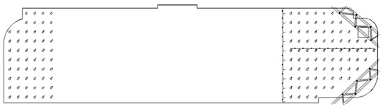
Figure 8.
Anti-floating pile layout plan.
(2) The calculation table of composite-anchor pile is shown in Table 6.
Table 6.
The calculation table of composite-anchor pile.
(3) Design of the number of composite-anchor piles.
The original design of anti-floating piles has a diameter of 800 mm and a length of 18.00 m. The main reinforcement consists of 20 third-grade steel strands (HRB400) with a diameter of 25 mm, arranged in 135 piles. The characteristic value of the uplift bearing capacity of each pile is 1400 kN.
After optimization calculation, the length of fully bonded piles is 17.00 m, the diameter is 800 mm, and the characteristic value of uplift bearing capacity is 1400 kN. The number and location are the same as those of the original anti-floating piles.
(4) Design of reinforcement for the rod body of composite-anchor piles.
For this, 1 × 7ϕs17.8 steel strand is used, with a design tensile strength of 1320 MPa; a total area of the anchor cable body ; and a single bundle of 1 × 7ϕs17.8 steel strand with a cross-sectional area of 191 mm2. The number of steel strands n = 2121/191 = 12.
(5) Verification of the anticorrosion service life for single-side coated welded pipes.
According to the provisions of 4.1.18 in the Technical Code for Building Pile Foundations (JGJ 94-2008) [24], “When the inner wall of the steel pipe pile is isolated from the outside world, the anti-corrosion of the inner wall can be ignored” and the steel strands in the steel pipe of this project can be ignored for anti-corrosion.
The composite uplift piles in this project are located below the groundwater level, and the medium for isolation from the outside world is DN65 welded pipe with a wall thickness of 3 mm. According to Table 4.1.18 of the Technical Code for Building Pile Foundations (JGJ 94-2008) [24], the corrosion rate on one side below the water level is 0.03 mm/y.
The single-sided corrosion life of DN65 welded pipe = 3 mm/0.03 mm/y = 100 × y > 50 × y
The single-side corrosion life of welded pipe meets the design requirements.
(6) Parameters of composite-anchor pile.
After the above preliminary design stage and considering the construction method of fully bonded piles, the parameters of the uplift piles are finally determined in this chapter:
① The pile body diameter is 800 mm, the effective pile length is 17.0 m, and the pile body concrete strength is C25.
② The number of piles is 135.
③ There are 4 composite-anchor cables set up as the main reinforcement, each consisting of 3 1 × 7ϕs17.8 steel strands. The effective length of the main reinforcement is 17.7 m, consisting of DN65 high-strength steel pipes, grout, and 4 × 3ϕs17.8 steel strands.
④ Each bundle of composite-anchor cables is provided with a DN65 high-strength steel pipe on the outside, with the bottom tapered and sealed. The steel pipes are connected by 150 mm-long DN80 high-strength steel pipe sleeve welds.
⑤ The high-strength steel pipe is provided with centering supports at a spacing of 3 m.
⑥ The characteristic value of the uplift bearing capacity of a single pile is 1400 kN.
5. Conclusions
This study aims to compare the load-bearing characteristics of traditional reinforced concrete uplift piles with composite-anchor piles. Enhanced field tests and numerical simulation methods were utilized to analyze the factors that influence the load-bearing capacity of composite-anchor piles. The results indicate that, when considering the same low reinforcement ratio (0.75%) and construction method, composite-anchor piles exhibit an equivalent load-bearing capacity as traditional piles. However, when the dry hole method is employed, the load-bearing capacity of composite-anchor piles increases by 18% compared to traditional piles.
Furthermore, load test curves conducted on site demonstrate that the displacement curve of the pile top during the loading of composite-anchor piles exhibits a gradual change over time, indicating a more uniform stress transfer. An analysis of load-bearing capacity parameters obtained from a numerical simulation reveals that modifying the structure of the composite-anchor cable within the pile can effectively enhance the overall load-bearing capacity of the uplift pile. From an economic and environmental perspective, altering the structure of the internal anchor cable not only simplifies construction and reduces construction time, but also minimizes damage to the surrounding soil, ensuring soil stability.
Based on comprehensive experimental and simulation results, it was observed that the load-bearing capacity of composite-anchor piles is closely linked to the frictional resistance at the interface of the composite-anchor cable inside the pile. However, current codes and standards lack a quantitative method to assess this type of internal interface frictional resistance. Therefore, this study proposes a specific method for calculating the load-bearing capacity and successfully applies it to projects conducted in the Fangshan area of Beijing. This promotes the future utilization and advancement of this type of pile.
In the Fangshan area projects, replacing traditional piles with composite-anchor piles reduced steel consumption by 41.74% and lowered project costs by approximately 25.47%. The economic benefits were substantial. Additionally, utilizing the dry hole method for construction resolved issues such as tight project schedules, noise disturbances, and the environmental impact of mud. Therefore, composite-anchor piles also exhibit positive environmental benefits and warrant widespread promotion and application.
Author Contributions
Conceptualization, Z.M. and J.J.; methodology, J.J.; formal analysis, J.J.; data curation, J.J.; writing—original draft preparation, J.J.; writing—review and editing, Z.M. and J.J.; supervision, L.C. and Y.W. All authors have read and agreed to the published version of the manuscript.
Funding
The study described in this paper was supported by the Talent Fund of Beijing Jiaotong University (2022XKRC005).
Institutional Review Board Statement
Not applicable.
Informed Consent Statement
Not applicable.
Data Availability Statement
The data presented in this study are available upon request from the corresponding author. Due to the fact that the work in the study was carried out by different authors without a shared folder, and some data originated from actual engineering projects involving certain privacy concerns, these data are not publicly available.
Conflicts of Interest
Author Zongyuan Mao was employed by the company China Building Technique Group Co., Ltd. The remaining authors declare that the research was conducted in the absence of any commercial or financial relationships that could be construed as a potential conflict of interest.
Abbreviations
| A0 | Converted sectional area |
| As Apy | Cross-sectional areas of ordinary steel bars and steel strands |
| d1 | Equivalent diameter of the steel strands |
| d2 | Inner diameter of high-strength steel pipe |
| d3 | Outer diameter of the high-strength steel pipe |
| ftk | Standard value of axial tensile strength of pile material |
| fy, fpy | Design values of tensile strength for steel bars and steel strands |
| Ggp | Equivalent pile–soil weight of single pile |
| Gp | Weight of single pile |
| l1 | The bond length of steel strands within the grout |
| l2 | The bonding length between the cement grout and the inner wall of the steel pipe |
| l3 | The bond length between the steel pipe’s outer wall and the pile concrete |
| li | Pile length in the i-th layer of rock (or soil) |
| N | Design value of axial tension at the pile top under basic load effect combinations |
| Nk | Standard value of tension force on single pile |
| qsik | Standard value of the ultimate lateral resistance of the i-th layer of rock (or soil) on the pile-side surface |
| Qck | The minimum frictional resistance of the interfaces within the pile |
| T | Characteristic value of uplift bearing capacity of single pile |
| Tgk | Calculated value of the ultimate bearing capacity of single pile |
| Tuk | Calculated value of the ultimate bearing capacity of single pile |
| ui | Perimeter of pile |
| ul | The perimeter of outer boundary of the pile group |
| σck | Vertical tensile stress at pile top under standard load combination |
| τ1 | The ultimate bond strength between the steel strand and the grout |
| τ2 | The ultimate bond strength between the cement grout and the inner wall of the steel pipe |
| τ3 | The ultimate bond strength between the outer wall of the steel pipe and the concrete of the pile shaft |
| λip | Uplift coefficient of the i-th layer of rock (or soil) |
| ωmax | Maximum crack width |
| ωlim | The limitation of crack width corresponding to the crack control level |
References
- Jin, B.; Lu, T.; Li, S.; Yin, K. The effect of groundwater buoyancy on the structural safety of underground buildings. Civ. Archit. Environ. Eng. 2010, 32, 56–60. [Google Scholar] [CrossRef]
- Tang, S.W.; Yao, Y.; Andrade, C.; Li, Z.J. Recent durability studies on concrete structure. Cem. CoCr. Res. 2015, 78, 143–154. [Google Scholar] [CrossRef]
- Agarwala, S.; Netula, O. Study of corrosion control of underwater piles. Imp. J. Interdiscip. Res. 2017, 3, 905–908. [Google Scholar]
- Zhao, Y. Overview of rust cracking of concrete structures caused by steel corrosion. J. Southeast Univ. 2013, 43, 1122–1134. [Google Scholar] [CrossRef]
- Liu, Y.; Hu, X.; Ma, Y.; Liu, S. Application of post-grouting technology in cast-in-place pile in silty sand stratum. Bridge Constr. 2019, 49, 155–165. [Google Scholar]
- Qian, D. Research on the compressive and tensile properties of branch pile. Geotech. Mech. 2003, 24, 517–520. [Google Scholar]
- Shelke, A.; Patra, N.R. Effect of arching on uplift capacity of single piles. Geotech. Geol. Eng. 2009, 27, 365–377. [Google Scholar] [CrossRef]
- Huang, M.; Ren, Q.; Wang, W.; Chen, Z. Analysis of ultimate bearing capacity of uplift piles under deep excavation conditions. Chin. J. Geotech. Eng. 2007, 180, 1689–1695. [Google Scholar] [CrossRef]
- Wang, Q.; Ma, J.; Xiao, Z.; Chen, W.; Ji, Y. Field Test on Uplift Bearing Capacity of Rock-Socketed Belled Piles. KSCE J. Civ. Eng. 2020, 24, 2353–2363. [Google Scholar] [CrossRef]
- Feng, S.-J.; Fu, W.-D.; Chen, H.-X.; Li, H.-X.; Xie, Y.-L.; Lv, S.-F. Field tests of micro screw anchor piles under different loading conditions at three soil sites. Bull. Eng. Geol. Environ. 2021, 80, 127–144. [Google Scholar] [CrossRef]
- Qian, J.; Ma, X.; Li, W.; Huang, M.; Wang, W. Centrifugal model test and in-situ test analysis of pile side grouting uplift pile. Geomechanics 2014, 35, 1241–1246. [Google Scholar] [CrossRef]
- Li, B.; Fu, J. Analysis of uplift bearing capacity of pile based on ABAQUS. IOP Conf. Ser. Earth Environ. Sci. 2017, 61, 012097. [Google Scholar] [CrossRef]
- Ni, P.; Mei, G.; Zhao, Y. Numerical investigation of the uplift performance of prestressed fiber-reinforced polymer floating piles. Mar. Georesources Geotechnol. 2017, 35, 829–839. [Google Scholar] [CrossRef]
- Emirler, B.; Tolun, M.; Yildiz, A. 3D Numerical Response of a Single Pile Under Uplift Loading Embedded in Sand. Geotech. Geol. Eng. 2019, 37, 4351–4363. [Google Scholar] [CrossRef]
- Yu, Y.-C.; Ren, W.-X.; Yin, Y.-G.; Luo, X.-G. Numerical simulation and field tests on vertical load bearing behaviour of bored root piles. Comput. Geotech. 2023, 159, 105453. [Google Scholar] [CrossRef]
- Levacher Daniel, R.; Sieffert, J.G. Tests on Model Tension Piles. J. Geotech. Eng. 1984, 110, 1735–1748. [Google Scholar] [CrossRef]
- He, L.; Chen, X.; Wang, Z.; Han, Y.; Su, T.; Dai, G.; Zhang, E.; Long, Z. A case study on the bearing characteristics of a bottom uplift pile in a layered foundation. Sci. Rep. 2022, 12, 22457. [Google Scholar] [CrossRef]
- Ilamparuthi, K.; Dickin, E.A. The influence of soil reinforcement on the uplift behaviour of belled piles embedded in sand. Geotext. Geomembr. 2001, 19, 1–22. [Google Scholar] [CrossRef]
- Goel, S.; Patra, N.R. Prediction of load displacement response of single piles under uplift load. Geotech. Geol. Eng. 2007, 25, 57–64. [Google Scholar] [CrossRef]
- Mao, Z.; Jiang, J.; Guo, H.; Wang, E. Development and Mechanical Property Analysis of a Novel Uplift Pile Incorporating Composite Anchors. Buildings 2023, 13, 2029. [Google Scholar] [CrossRef]
- Li, Z.; Zhao, J.; Liu, T.; Guan, C.; Liu, Y.; Zhu, W.; Liu, L. Capacity Change of Piles in Loess under Cyclic Axial Tension or Compression Load. Int. J. Geomech. 2023, 23, 04023182. [Google Scholar] [CrossRef]
- Conte, E.; Pugliese, L.; Troncone, A.; Vena, M. A Simple Approach for Evaluating the Bearing Capacity of Piles Subjected to Inclined Loads. Int. J. Geomech. 2021, 21, 04021224. [Google Scholar] [CrossRef]
- Ministry of Housing and Urban-Rural Development. JGJ 106-2019 Technical Code for Testing of Building Foundation Piles; China Architecture & Building Press: Beijing, China, 2019. [Google Scholar]
- Ministry of Construction. JGJ 94-2008 Technical Code for Testing of Building Pile Foundations; China Architecture & Building Press: Beijing, China, 2008. [Google Scholar]
- Mao, Z.; Guo, H.; Wu, Y.; Wang, E.; Li, X. Development of a New Uplift Pile with Prestressed Semi-Bonded Composite Anchor. Buildings 2022, 12, 1478. [Google Scholar] [CrossRef]
- Soga, K.; Alonso, E.; Yerro, A.; Kumar, K.; Bandara, S. Trends in large-deformation analysis of landslide mass movements with particular emphasis on the material point method. Géotechnique 2016, 66, 248–273. [Google Scholar] [CrossRef]
- Troncone, A.; Pugliese, L.; Parise, A.; Conte, E. A simple method to reduce mesh dependency in modelling landslides involving brittle soils. Géotech. Lett. 2022, 12, 167–173. [Google Scholar] [CrossRef]
- Zhang, X.W.; Tang, X.W.; Shao, Q.; Bai, X. The uplift behavior of large underground structures in liquefied field. Appl. Mech. Mater. 2011, 90–93, 2112–2118. [Google Scholar] [CrossRef]
- Ministry of Construction. GB50010-2010 Beijing: Code for Design of Architecture & Concrete Structures; China Architecture & Building Press: Beijing, China, 2010. [Google Scholar]
Disclaimer/Publisher’s Note: The statements, opinions and data contained in all publications are solely those of the individual author(s) and contributor(s) and not of MDPI and/or the editor(s). MDPI and/or the editor(s) disclaim responsibility for any injury to people or property resulting from any ideas, methods, instructions or products referred to in the content. |
© 2024 by the authors. Licensee MDPI, Basel, Switzerland. This article is an open access article distributed under the terms and conditions of the Creative Commons Attribution (CC BY) license (https://creativecommons.org/licenses/by/4.0/).