1. Introduction
Wire arc additive manufacturing (WAAM) is widely used in many industries due to its excellent advantages. It reduces the production time and allows net-shape manufacturing. It has also gained attention for its potential applications in the maintenance and repair of structural defects. In WAAM, the localized heat energy is applied to the wire for the deposition, which results in high thermal gradients. Depending on the process conditions, the thermal history of the AM deposition could vary, and it affects the microstructural features, leading to a change in the material properties and structural performance of the AM parts.
Many studies have been actively conducted on the aluminum microstructure in the AM process. Kazmi and coworkers [
1] investigated the effects of the deposition speed and current on the morphology of the bead in WAAM of ER-4043 aluminum alloy. He and coworkers [
2] performed microscopic analysis on the 4043 Al alloy fabricated by WAAM. They investigated microstructure evolution, tensile strength, and fatigue life cycles of the 4043 Al alloy. Wang et al. [
3] examined the microstructure and mechanical properties to investigate the effects of the mean and alternating stresses on the ratcheting behaviors of 4043 Al alloy fabricated by WAAM. Gu and coworkers [
4] studied the micropore evolution in the WAAM Al-Cu6.3 and Al-Mg4.5 alloys using X-ray diffraction tomography (XRT). It was found that after interlayer rolling, the number, size, volume, and roundness of micropores in the alloys decreased with an increase in the rolling loads. Su et al. [
5] performed a microstructural analysis on the Al-Mg alloys fabricated by WAAM. They examined the influence of heat input on the microstructure evolution and change in mechanical properties of the Al-Mg alloy. They also reported that the values of microhardness vary with a change in wire-feed speed, while the travel speed does not significantly affect the microhardness.
Many studies have also been conducted to understand how the AM parameters affect the microstructural features and mechanical properties for process optimization. Kohler et al. [
6] examined the porosity, temperature distribution, residual stress formation, and hardness of Al-4046 fabricated by WAAM. Zuo et al. [
7] investigated the microstructure, mechanical properties, and fracture morphology of 5356 Al alloy fabricated by WAAM with a TIG-MIG hybrid heat source. They analyzed the influence of the heat-treated temperature on the microstructure evolution such as the grain growth and phase transformation, which lead to the change in mechanical properties and structural performance. Analyses found that an increase in bypass current in WAAM of 2219 Al alloy increases the size of columnar grains, which leads to the strengthening of Al alloy [
8]. Ortega et al. [
9] studied the effects of the travel speed and welding power on geometric accuracy in the deposition of ER 4043 WAAM. Kumar et al. [
10] investigated the influence of the scanning speed and welding current on the cold metal transfer (CMT) AM process with a focus on microstructural aspects. Doumenc et al. [
11] studied the relationship among microstructure features, hardness, and residual stress in WAAM of Aluminum alloy 6061 for two deposition patterns: alternate and unidirectional scanning. Chen and coworkers [
12] investigated the crack evolution characteristics in Al-Zn-Mg-Cu alloy fabricated by WAAM through a combination of thermomechanical simulations and microstructure analyses. Yang et al. [
13] studied the heat treatment methods to improve the microstructure and mechanical properties of AlSi7Mg0.6 parts fabricated by WAAM-CMT. They proposed the optimal method of heat treatment, which can improve the mechanical properties including the elastic modulus, yield strength, and so on. Sun and coworkers [
14] analyzed the WAAM process for AL/steel dissimilar joints to understand how the interpass temperature changes the microstructural features and material properties.
Thermal-induced residual stress/warpage is one of the main concerns in the WAAM process. Much research has been performed to resolve this issue. Wang et al. [
15] developed the numerical model to study the thermal-induced warpage and proposed the deposition strategy for reduction in buckling of the thin plate. Huang and coworkers [
16] performed X-ray diffraction (XRD) and contour method analyses to study the influence of strain hardening and heat treatment on the residual stress and warpage of thin plates. Liu et al. [
17] examined the effects of welding speed on material properties of a 6061-T6 aluminum joint. Lee and coworkers [
18] studied the influence of the welding speed on microstructure evolution in dissimilar Al/Cu sheets. Analyses suggest that extremely high welding speed could lead to strong laser weldment. Benyounis et al. [
19] investigated the influence of the process parameters for carbon steel welding such as laser power, scanning speed, and focal point position on the welding performance and reliability of weld structure.
Numerical analysis has provided insights into the understanding of the process, properties, and performance of AM parts. Kohler et al. [
6] performed FE simulations to analyze the thermal and stress distributions of WAAM of Al-4046. In their simulations, sequentially coupled thermomechanical constitutive equations were employed. Gannon et al. [
20] performed sequentially coupled FE simulations to study how the deposition sequence affects the thermal profiles and production of residual stress and distortion. Biswas and coworkers [
21] conducted FE simulations to understand the effects of the welding sequence on the distortion of stiffened plate panels. Ujjwal et al. [
22] conducted a finite element study on the effects of clamping position on the residual stress generation in WAAM. Caiazzo et al. [
23] implemented a molten pool model into their numerical model for the study of residual stress in DED of aluminum alloy 2024. In their model, the shape and rate of deposition can be monitored, allowing the feeding rate to be taken into account in WAAM simulation. Liang et al. [
24] proposed the modified inherent strain method to investigate the residual distortion of a rectangular contour wall. The proposed model allows the prediction of the inherent strains, which can be applicable to the part model for the DED simulations. Ge et al. [
25] developed the numerical model for WAAM of the 2Cr13 part considering the transient thermal transfer and thermo-elastoplastic coupled behaviors of material. From their combination study of numerical simulation and experimental characterization, the relationship among thermal profiles, microstructure evolutions, and defect production was analyzed. Wu et al. [
26] investigated the residual stress and distortion generation of Ti-6Al-4V and Inconel 718 WAAM components. In their study, the flow of molten metal and the shape and size of molten pool were analyzed. Bai et al. [
27] developed the numerical model to analyze the fluid flow and temperature evolution in multilayer deposition of WAAM. In their model, the equations of fluid mechanics and the solid-liquid phase change were incorporated with the molten pool dynamics. The prediction of the shape and size of wire deposition from the numerical simulations was validated by comparison with experiment measurements. The various types of heat source model have also been studied in simulations of the WAAM process. Kong and coworkers [
28] implemented the double ellipsoidal and the cylindrical volumetric heat source models to their numerical model to examine thermal profiles and residual stress in the hybrid laser-GMA welding. Batut et al. [
29] used the heat source model of Gaussian distribution in direct metal deposition of Ti6Al4V. The laser absorption coefficient, the shape factor of the Gaussian distributed heat flux, and the laser spot radius were taken into account in the model. Mirkoohi et al. [
30] modeled the heat source as line heat flux using the delta function for 2D simulation. Selvamani et al. [
31] reported their development of the thermal model for the CMT welding process. The model is based on the earlier model proposed by Goldak et al. [
32]. In the model, the heat flux represents the sum of time-dependent heat inputs as a function of current and voltage.
Aluminum 6061 is a widely used alloy for its excellent material properties. It exhibits high weldability, excellent corrosion resistance, and a high strength-to-weight ratio [
33]. Many industries are adapting the WAAM technique for the production of components with complex geometry [
34]. However, the residual stress and warpage issues, which result from thermal gradients during the AM deposition, have not been resolved yet. Among the AM process parameters, the deposition pattern and travel speed could significantly affect the thermal gradients and cooling rates, which are crucial in the structural reliability and life cycle of the components fabricated by AM, as they determine the microstructural features, leading to the formation of residual stress and distortion.
In order to enhance the structural reliability of AM parts, it is necessary to understand the underlying mechanism of thermal-induced warpage and residual stress generation in WAAM process. However, AM process parameters are normally chosen based on experience. Among such parameters, the deposition pattern and travel speed could have a great influence on thermal profiles, which could lead to the generation of residual stress and warpage. However, the effects of the deposition patterns and travel speeds have not been explicitly understood. In the present study, analyses focus on how such parameters affect thermal profiles, residual stress, and warpage formation for the application of WAAM Al 6061 alloy.
2. Materials and Methods
In this work, thermomechanical simulations were conducted to analyze the effects of the AM deposition patterns and travel speeds on residual stress and distortion in the deposition. Thermal gradients induced by localized heat could generate residual stress and distortion. In thermal analysis, the heat transfer from conduction, convection, and radiation has been considered in the present numerical model as Equations (1)–(3).
where
is the heat capacity;
is the density; and
is the thermal conductivity.
Here, h is the convection coefficient, is the emissivity and is the Stephan–Boltzmann constant.
For the heat source modeling, the double ellipsoidal model proposed by Goldak’s [
32] was used for WAAM deposition. The heat energy is applied to the wire as a volumetric heat source, which is defined as follows:
and
are parameters to specify the front and the rear size, respectively.
Q is the AM deposition energy.
Table 1 shows the heat source parameters used in the study, which are based on the previous reference [
35].
A thermomechanical constitutive equation is employed in this work. The isotropic material and the small elastic deformation are assumed in the hypoelastic formulation. The strain is decomposed into elastic, plastic, and thermal parts as follows:
where
is the total strain;
is the elastic strain;
is the plastic strain; and
is the thermal strain. In the hypoelastic formulation, the trial stress is calculated using the generalized Hooke’s Law as Equation (7).
Once the trial stress is calculated, the stress is relaxed such that the final stress satisfies the yield criterion using radial return mapping.
6061-T6 Al alloy is widely utilized in the aerospace and automotive industries due to its excellent performance. In this work, it was chosen as a material for both the substrate and the wire. Such a choice was made for its application of AM in maintenance and net-shape manufacturing.
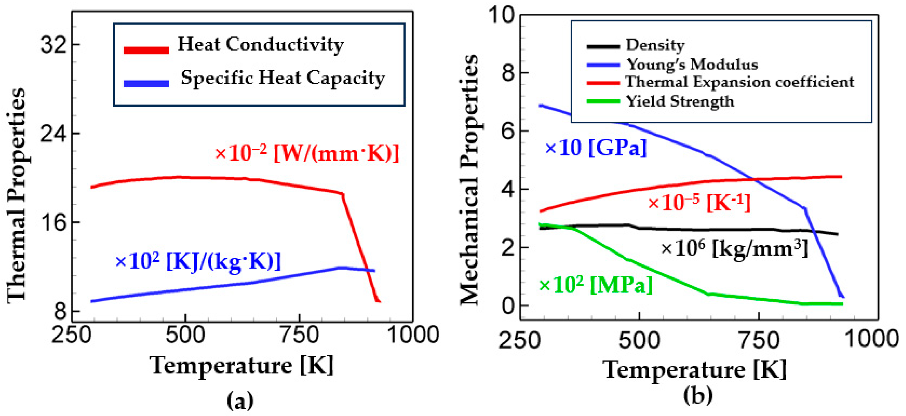
Figure 1 shows the material properties used in the present study. The values of the properties are from the reference of [
36].
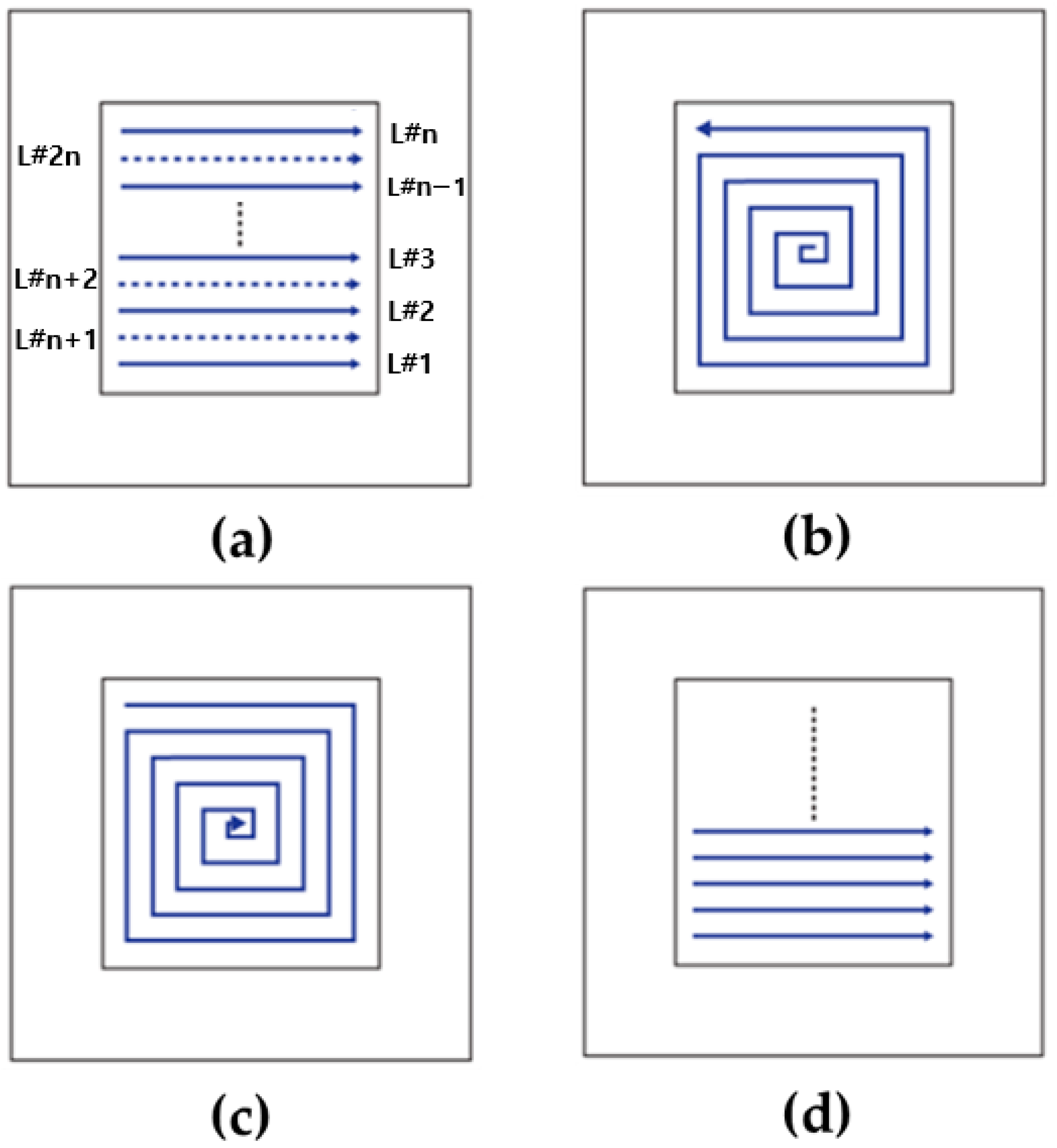
In the present study, four deposition patterns are examined as shown in
Figure 2: alternate, in–out spiral, out–in spiral, and raster. Note that the alternate pattern has the interval between the deposition. In
Figure 2a, the deposition sequence of the alternate pattern is illustrated with the line number. For example, “L#1”and “L#2” indicate “Line #1” and “Line#2”, respectively. In the case of the alternate pattern, the solid lines are deposited first (i.e., from L#1 to L#n), and then the dashed lines are deposited between the solid lines, as the line numbers indicate in
Figure 2a. The paths of the out–in and in–out deposition are the contour, while the alternate and raster follow line paths. The alternate and the raster deposition are discontinuous, while the paths of the in–out and the out–in are continuous. Different from the raster, the alternate deposition strategy leads to more lag time between the nearest deposition paths. In this work, analyses focus on how such deposition patterns affect thermal profiles such as the temperature distribution and cooling rate, which eventually result in the residual stress and warpage.
In this work, commercial FE software, ABAQUS 2019, was used for the WAAM process simulations. The ABAQUS user subroutine DFLUX was used to define the heat flux and deposition path.
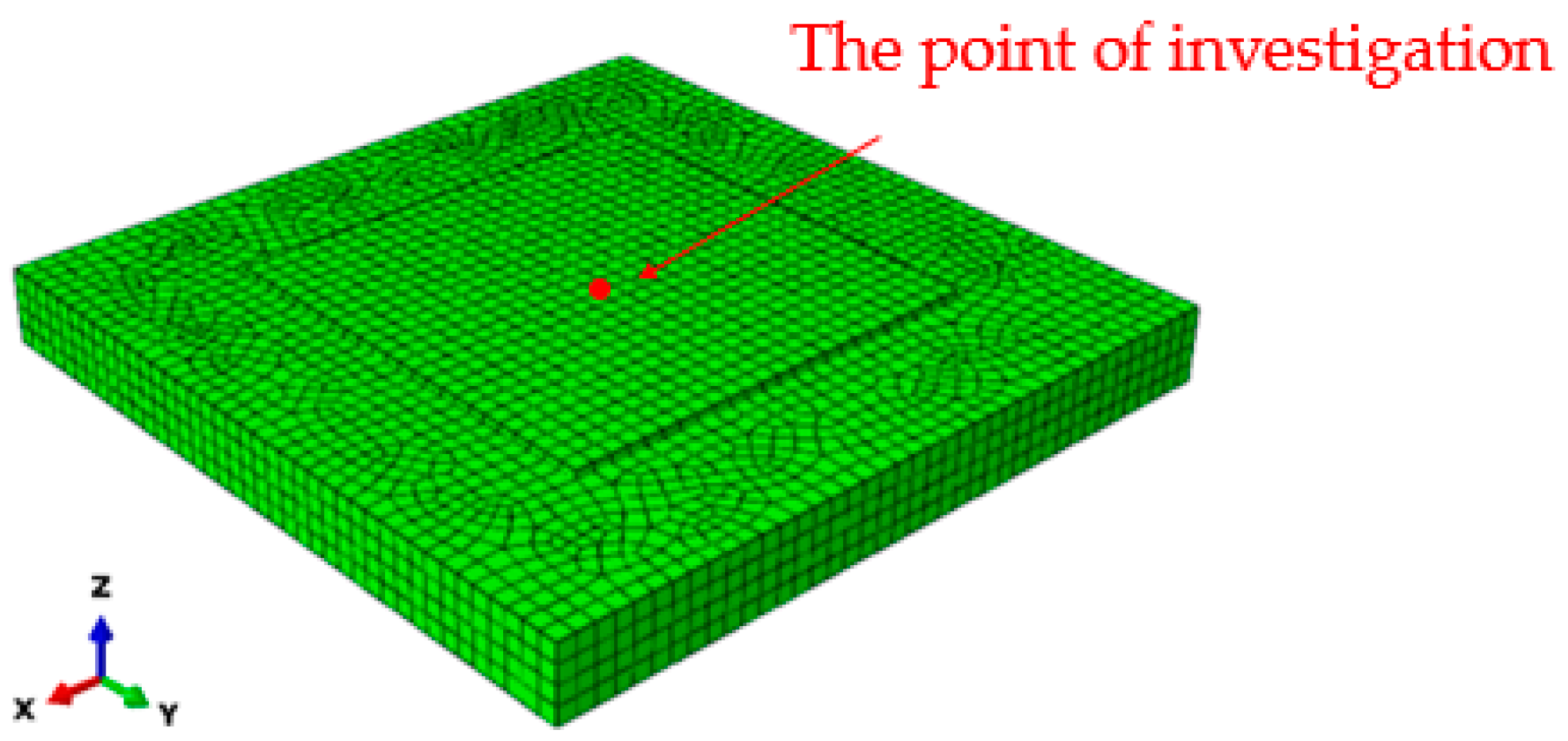
Figure 3 shows the finite element model used in the present study. The dimensions of the substrate were modeled as 260 mm × 260 mm × 25 mm and two AM deposition layers of 120 mm × 120 mm × 6.0 mm. The model was discretized with 17,687 elements. The deposition layer was modeled with 7847 elements. Sequentially coupled thermomechanical simulations were conducted. First, thermal simulations were performed using ABAQUS DC3D8 elements, an 8-node linear brick element for thermal analysis. Then, mechanical simulations were performed using ABAQUS C3D8 elements, the 8-node linear brick element. The initial time step was set to be 0.01 s and the automatic time increment was chosen for the simulations so that the size of the time step could be adjusted based on the solution convergence rates. In order to examine the effects of deposition patterns on thermal profiles, the temperature evolution for the different deposition patterns will be analyzed at the point of investigation as shown in
Figure 3.
3. Results and Discussions
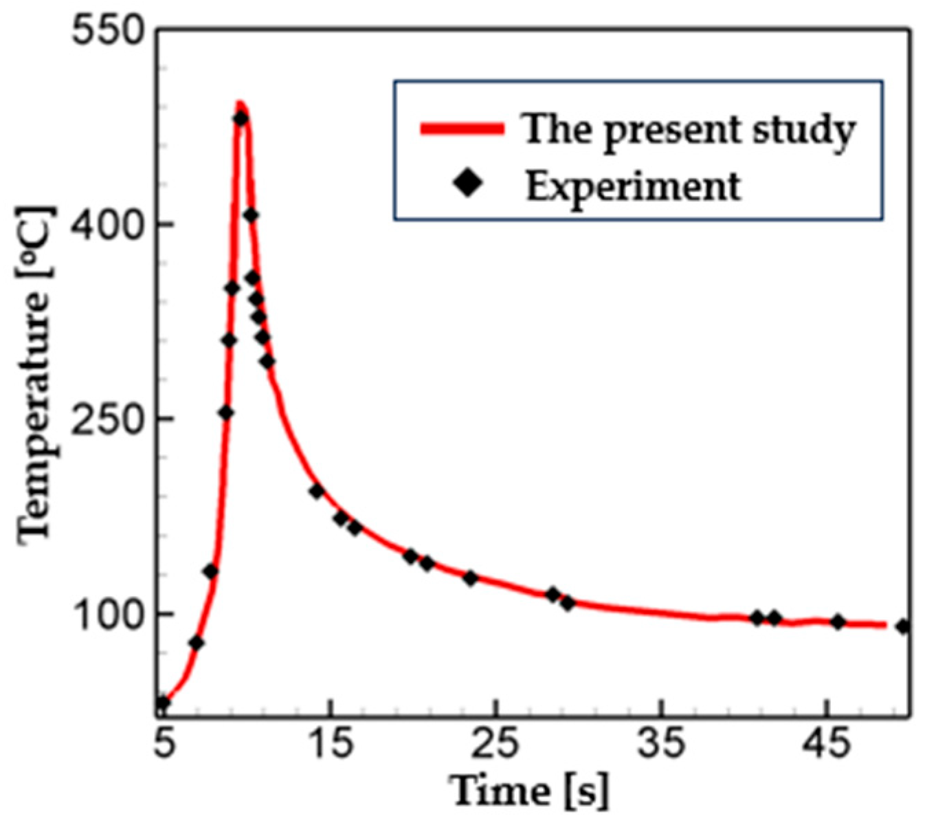
For verification of the numerical model, the temperature calculations were compared with the experimental measurements from Bardel et al. [
37] at the point located 4 mm away from the deposition line. They measured temperature profiles using K-type thermocouples (diameter 80 mm) for experiments. Following the experiment setup, the deposition speed was set to be 45 cm/min. More details on the experiment setup are available in [
37]. As shown in
Figure 4, the temperature profiles from the simulation and experiment are in good agreement with each other.
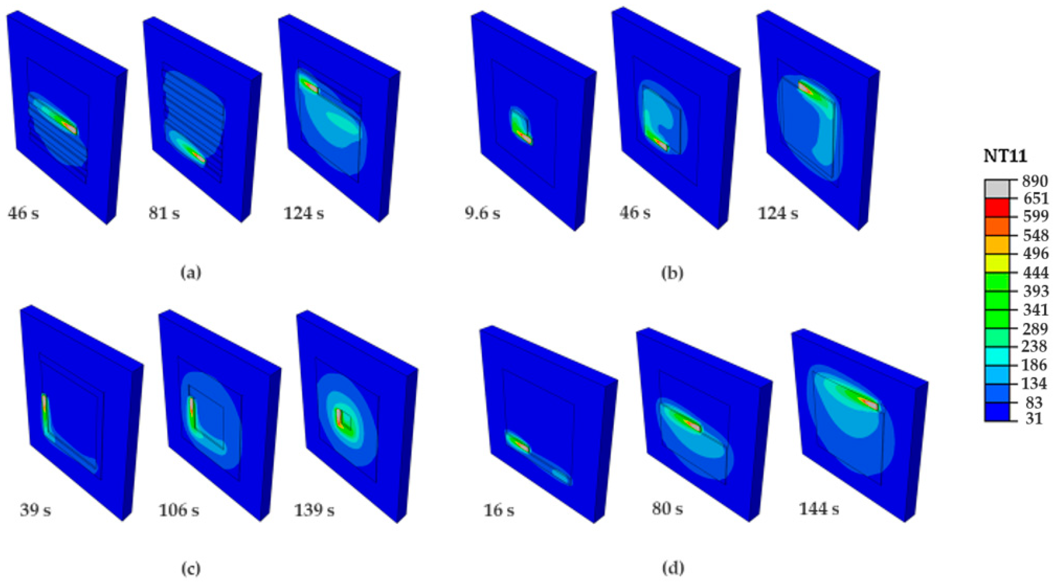
In the WAAM process, the localized heat source energy is applied to the wire, leading to an inhomogeneous thermal gradient. That could affect the thermal profiles of the AM deposition such as the temperature distribution and cooling rate. To investigate this issue further, the time evolution of temperature distributions for the different deposition strategies were analyzed as shown in
Figure 5. It is worth noting that the alternate and raster patterns follow discontinuous parallel lines with multiple starts and ends. The in–out and out–in patterns consist of continuous spiral depositions. These continuous contours allow the number of tool-path passes to be reduced. However, the in–out and out–in require a large number of turns, which could produce excessive heat input in a small region at the beginning and end of the deposition, respectively. Therefore, in the case of spiral-type patterns, the more concentrated heat energy is applied to the substrate than the line-type patterns due to such characteristics of the scanning paths. As shown in
Figure 5, the alternate pattern has the smallest region whose temperature is greater than 390 °C (green contour) among the deposition pattern considered. This can be explained by the deposition interval between each scanning, which promotes the heat transfer to the surroundings. It is worth noting that the raster is also the line-type scanning pattern, which is the same as the alternate pattern. However, it scans without an interval, which results in a higher thermal gradient than the alternate scanning case.
In order to analyze the effects of the deposition pattern on thermal profiles, the temperature history at the center of the deposition layer is analyzed and plotted in
Figure 6. Among all the patterns considered, the out–in case has the highest peak temperature. The values of the peak temperature for the raster and the alternate are similar to each other. The in–out case shows the lowest value of peak temperature. As shown in
Figure 5c, a circular symmetric temperature distribution is formed in the out–in pattern deposition. This is mainly because heat is concentrated toward the center of the deposition layer, leading to the highest peak temperature. On the contrary, in case of the in–out pattern, heat is dispersed during the deposition.
Figure 6 also shows that the difference in the peak temperature between the alternate and the raster patterns is negligible. Note that the alternate pattern has an interval between the deposition while the raster does not. Analysis suggests that the interval between each deposition has no significant effect on the thermal profiles.
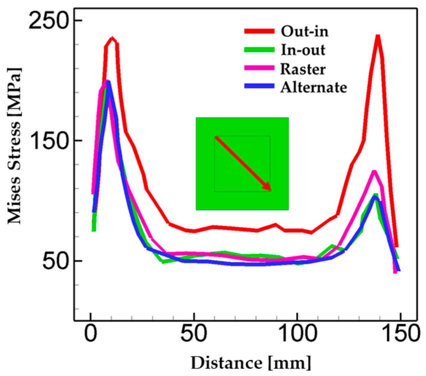
Figure 7 shows the Mises stress in the diagonal direction for the different deposition patterns. High levels of stress are generated at the corner of the deposition layer for all cases considered. The out–in pattern case leads to the highest residual stress throughout the deposition path and its maximum value was calculated as 235MPa. Such value is from 16% to 27% higher than other pattern cases (in–out: 27%, altyernate:19%, raster: 16%). This is mainly attributed to the heat being accumulated during the deposition due to its scanning characteristics, leading to higher peak temperature and thermal stress than other cases. The figure also shows that the raster pattern case has higher stress than the alternate case. The scanning strategies of the raster and the alternate are not significantly different. The only difference is that the alternate pattern has intervals between each deposition, which promotes more heat transfer to the surroundings. The results present that the type of deposition pattern significantly affects the thermal gradient and, thus, residual stress generation.
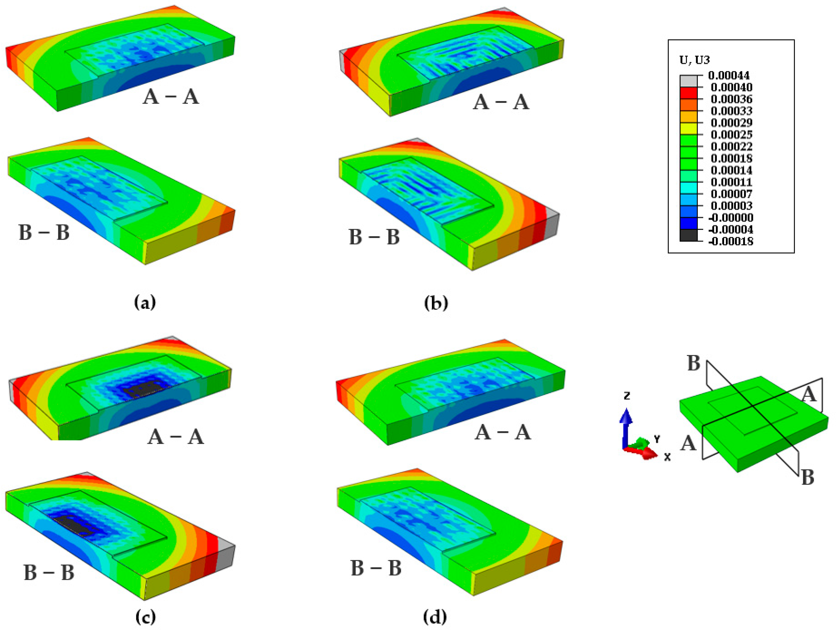
The inhomogeneous thermal gradient in AM deposition could lead to excessive distortion. Therefore, warpage was investigated to ensure structural integrity of AM parts. In this work, the AM deposition layer is built up in the z-direction.
Figure 8 shows the displacement distributions for different deposition patterns. Overall, the maximum warpage is found at the corner of the substrate, while the minimum displacement is located in the center for all types of patterns considered. This overall trend results from the compressive residual stress generated during deposition. Considering the heat transfer throughout the thickness of the substrate during the deposition, the temperature at the top surface is higher than the one at the bottom. As the substrate is clamped, the heat expansion generates compressive thermal stress. The higher thermal stress is applied at the top and the lower stress is applied at the bottom due to the temperature difference throughout the thickness. Such stress gradients lead to the bending of the substrate and the deposition layer. This explains the overall distortion trends of the substrate and deposition layer, which are observed in
Figure 8. Similar trends of distortion are also observed in other works, which show experimentally measured warpage, for example, single welding pass [
38]; WAAM multi-layer depositions [
39,
40,
41]; and a thin-walled rectangle deposited by multi-layered WAAM [
42]. Zubairuddin et al. [
38] investigated the distortion in the welding of 9Cr-1 Mo steel. Maximum distortion after removal of clamping was measured as 2.1 mm. It was reported that this was mainly because of the compressive residual stress near the welding line. Wacker et al. [
39] measured the welding distortion of multi-layer WAAM depositions. In their works, the distortion of the specimens was observed in the z direction (thickness direction) with a concave-up curvature. A comparative study of numerical and experimental results on the distortion of HSLA S460 WAAM was also reported [
40], which presented angular distortion in the multilayer of WAAM depositions. Prajadhiana et al. [
42] analyzed the distortion of the thin-walled rectangular component fabricated by twenty-five layers of WAAM depositions. Their comparison results between simulation and experiment demonstrate the concave distortion of samples, which is the same as in the present study.
It is interesting to note that the line-type patterns (i.e., alternate and raster) exhibit similar contours for warpage, while the spiral-type patterns (i.e., in–out and out–in) have different trends in the displacement distribution. Although the same level of heat source energy is applied to the substrate for all pattern cases, the amounts of cumulative heat in the center of the deposition layer are different depending on the type of pattern. For example, in case of the in–out pattern, only the heat source energy is applied to the center at the beginning of the deposition without any other heat additions.
Figure 5b shows that the intensity of the temperature contour at the center becomes weaker as time proceeds. On the contrary, in other pattern cases, the heat is transferred from the adjacent depositions in addition to the heat source energy. In case of the out–in pattern, as shown in
Figure 5c, the heat is concentrated toward the center of the deposition layer, showing a circular symmetric temperature distribution. The level of heat energy at the center is the highest among the cases considered in this study. Note that in
Figure 5c the heat from the adjacent depositions is transferred toward the center before the heat source reaches the center point. The temperature histories of
Figure 6 support this explanation as well. In
Figure 6, the out–in case has the highest peak temperature (T = 1080 °C). The values of the peak temperature for the raster and the alternate are similar to each other and come next (T = 866 °C). The in–out case shows the lowest value of peak temperature (T = 759 °C). For such reasons, the largest thermal stress and thus bending are generated in the case of the out–in pattern. This can explain why the negative displacement in the center of the deposition layer is observed in the out–in case, different from the other cases. The results so far suggest that the deposition pattern significantly affects thermal profiles such as peak temperature, heat accumulation, cooling rate, and others. Therefore, the deposition strategy could have a significant influence on the formation of warpage and residual stress in the AM parts.
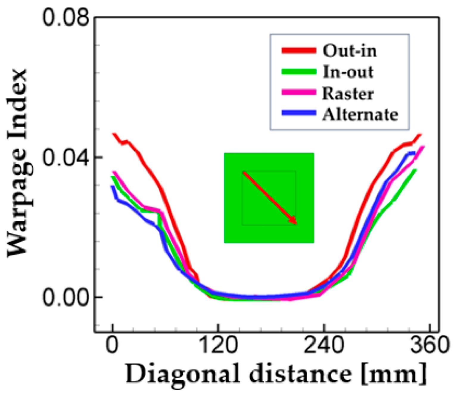
In
Figure 9, the warpage index is analyzed for the different deposition patterns along the diagonal direction. Note that the warpage index was determined by the normalized relative displacement by the substrate thickness. The relative displacement was calculated as the deflection in the z-direction at the corresponding position with respect to the minimum displacement (i.e.,
). Such an index was used to understand intuitively how much distortion is generated due to the AM deposition. The overall trend is that the minimum warpage is observed in the center, while the maximum warpage is located at the corner of the substrate. Another interesting finding is that the warpage for the out–in pattern is higher than other cases throughout the whole deposition path. In addition, the warpage for the out–in pattern is the most symmetric with respect to the center. This is mainly attributed to a circular symmetric temperature distribution due to its characteristic of the scanning path as described above. Note that a similar trend is also found in the Mises stress and displacement distributions in
Figure 7 and
Figure 8, respectively. Different from the contour-type patterns (i.e., in–out and out–in), the line-type depositions (i.e., raster and alternate) have similar trends and values of warpage, as shown in
Figure 9. Note that unlike raster deposition, the alternate scanning has an interval between each deposition. However, such a difference in the presence of intervals has little influence on the peak temperature Mises stress distribution, as analyzed above in
Figure 6,
Figure 7 and
Figure 8.
Analysis in
Figure 7 and
Figure 9 shows that the out–in case leads to the highest Mises stress and warpage. The line-type patterns (i.e., alternate and raster) do not show notable differences in residual stress and warpage. In the case of the in–out patterns, the values of maximum Mises stress and warpage have a tendency to be slightly lower than the line-type patterns. Analyses so far suggest that the deposition pattern directly influences the temperature distribution, thermal gradient, and cooling rate, which will affect the generation of residual stress and warpage.
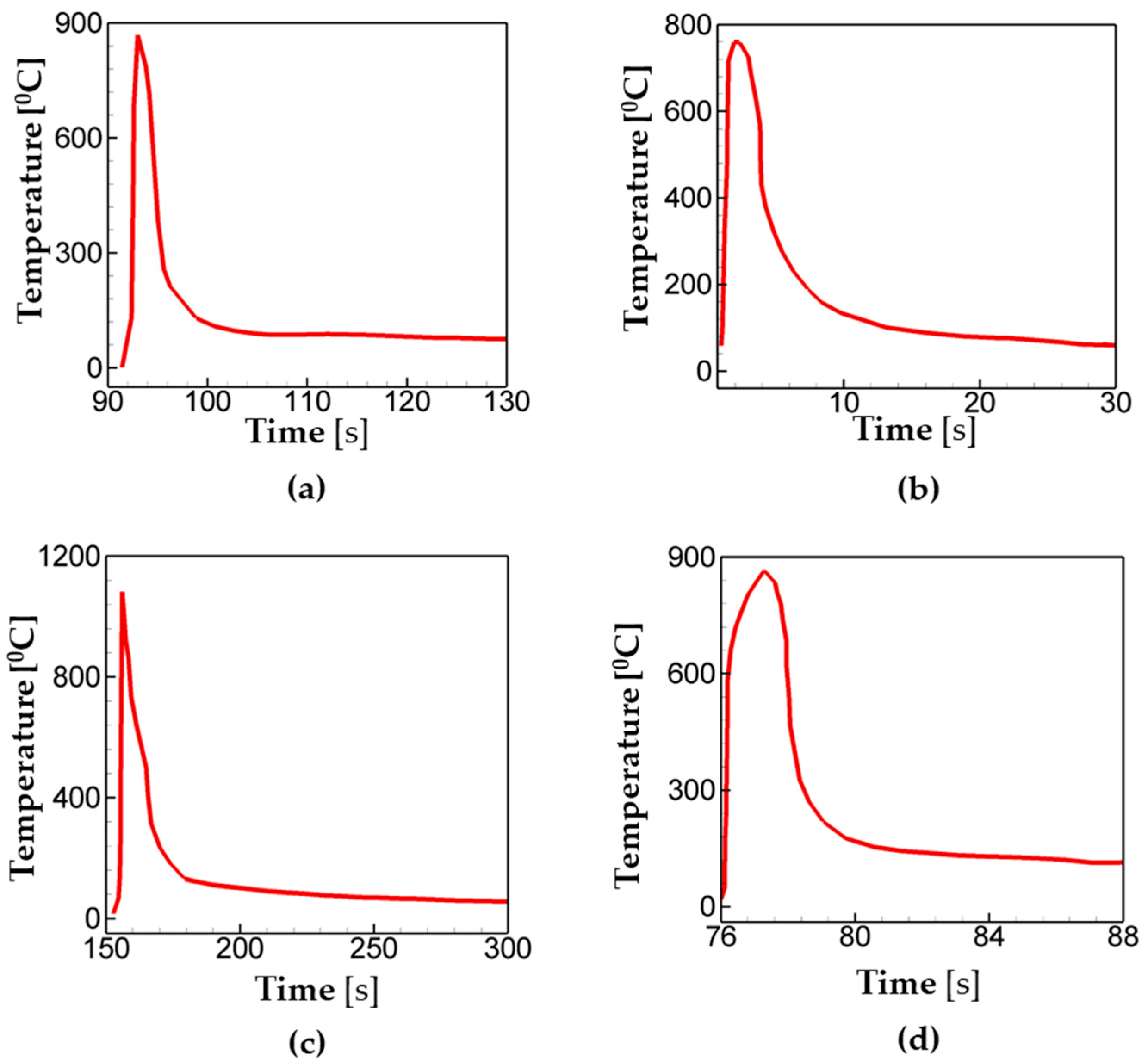
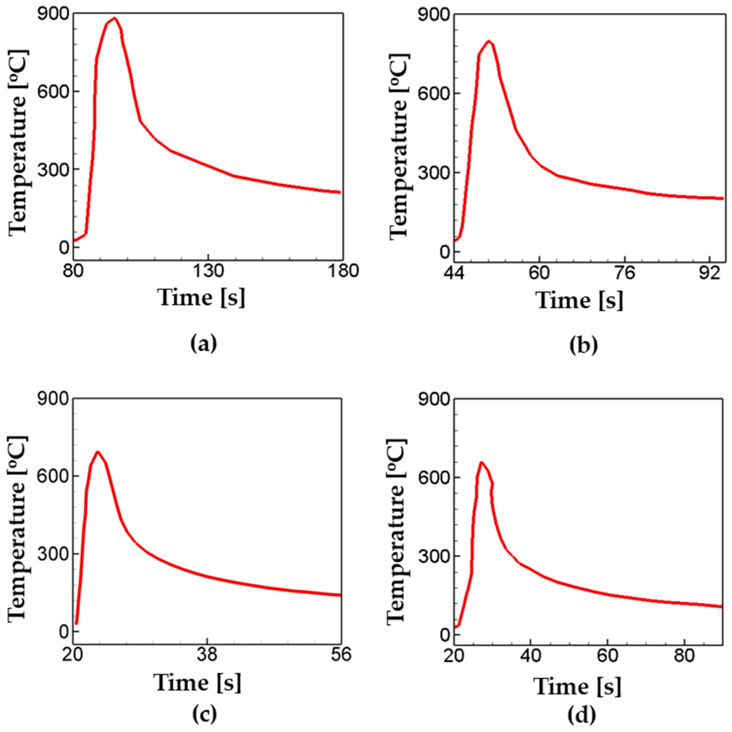
Next, the effects of the deposition travel speed on thermal profiles are analyzed. FE simulations were carried out with four different travel speeds: 50 mm/min, 100 mm/min, 150 mm/min, and 200 mm/min. The alternate deposition pattern was chosen for the analysis.
Figure 10 shows the temperature history for the different travel speeds. In the case of 50 mm/min, the peak temperature is 883 °C at t = 96 s, and the temperature drops below 300 °C at t = 126 s, which is 30 s after it reaches its peak value.
Figure 10 also shows that the peak temperature decreases with an increase in travel speed. The peak temperature is calculated as T = 784 °C, T = 696 °C, and T = 662 °C for a travel speed of 100 mm/min, 150 mm/min, and 200 mm/min, respectively. The faster the travel speed that is applied, the less time is available for the heat accumulation, which leads to lower levels of peak temperature.
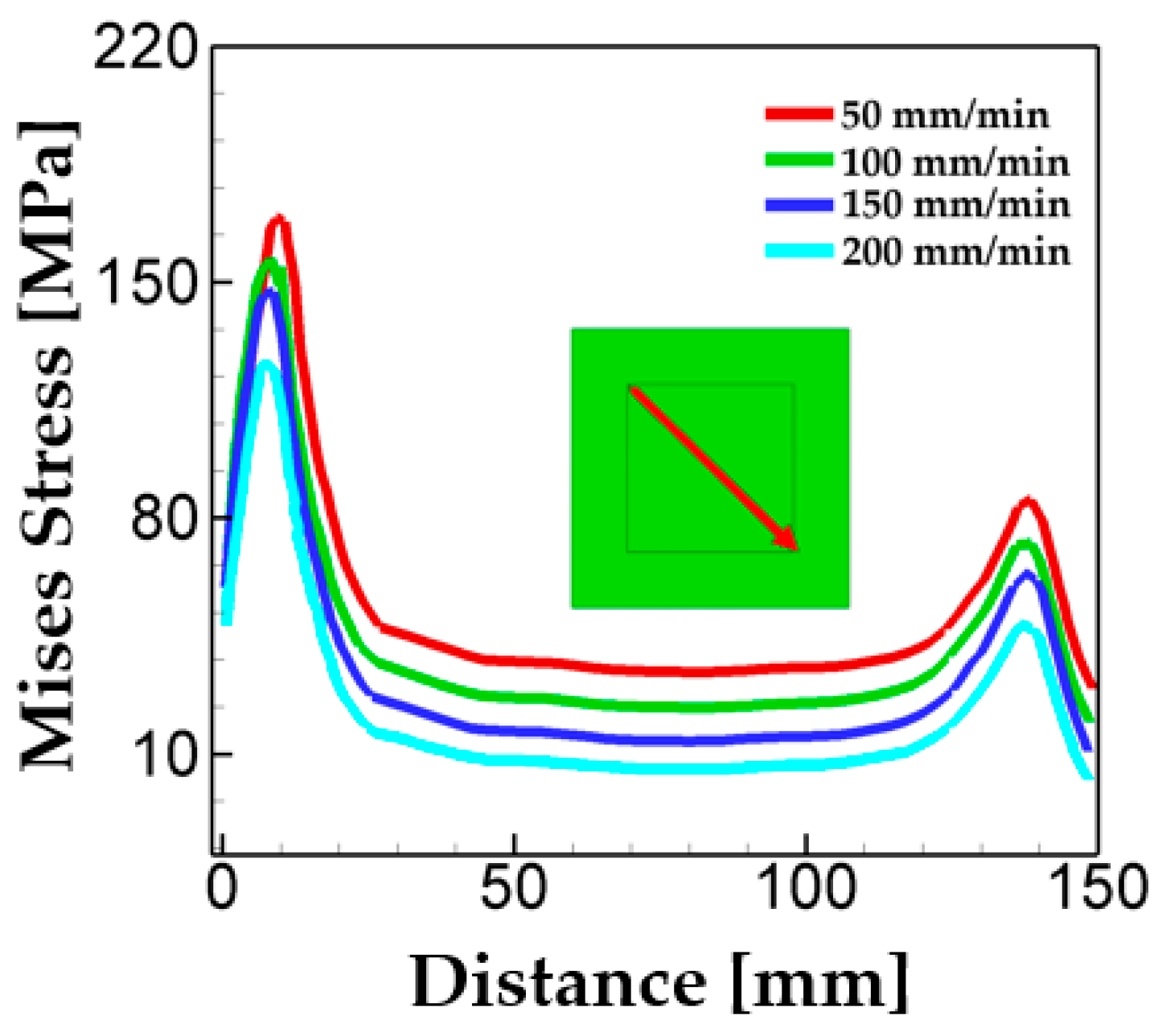
In order to investigate the influence of travel speed on residual stress generation, the maximum Mises stress at the end of deposition is analyzed and plotted as a function of distance along the diagonal direction in the deposition layer as shown in
Figure 11. The overall trend is that the generation of residual stress decreases with an increase in the travel speed. As noted above, the level of peak temperature and the amount of heat accumulation decrease with an increase in the travel speed. It is also worth noting that the rate of residual stress generation decreases as the travel speed increases. This is mainly because the thermal gradient decreases as the travel speed increases.


