Article

Fault-Tolerant Multiport Converter for Hybrid Distribution Systems: Configuration, Control Principles and Fault Analysis

by
Simone Negri
1,
Giovanni Ubezio
2 and
Roberto Sebastiano Faranda
3,*
1
Dipartimento di Elettronica, Informazione e Bioingegneria, Politecnico di Milano, 20133 Milan, Italy
2
E.C & C. srl, 23889 Santa Maria Hoè, Italy
3
Dipartimento di Energia, Politecnico di Milano, 20121 Milan, Italy
*
Author to whom correspondence should be addressed.
Appl. Sci. 2024, 14(10), 4024; https://doi.org/10.3390/app14104024
Submission received: 2 March 2024 / Revised: 2 May 2024 / Accepted: 5 May 2024 / Published: 9 May 2024

Abstract

:
Multiport converters (MCs) are widely adopted in many applications, from renewable energy sources and storage integration to automotive applications and distribution systems. They are used in order to interface different energy sources, storage devices and loads with one single, simple converter topology in contrast to the traditional approach, which can require different solutions made by two-port converters. MCs allow for a reduction in the number of components and cascaded conversion stages with respect to an equivalent system of two-port converters, resulting in reduced complexity, dimensions and costs, as well as in improved reliability and enhanced efficiency. Nevertheless, some aspects related to the design of MCs are still worth further discussion when MCs are applied to hybrid AC/DC distribution systems. First, most converters are developed for one specific application and are not modular in structure. Furthermore, many of the proposed solutions are not equally suitable for AC and DC applications and they can introduce significant issues in hybrid distribution systems, with earthing management being particularly critical. Even though most available solutions offer satisfying steady-state and dynamic performances, fault behavior is often not considered and the possibility of maintaining controllability during faults is overlooked. Building on these three aspects, in this paper, a new MC for hybrid distribution systems is presented. An innovative circuit topology integrating three-phase AC ports and three-wire DC ports and characterized by a unique connection between the AC neutral wire and the DC midpoint neutral wire is presented. Its control principles and properties during external faults are highlighted, and extensive numerical simulations support the presented discussion.

1. Introduction

The ongoing changes in distribution systems are creating new interest in innovative solutions to enhance system performance. In particular, hybrid AC/DC distribution systems are a promising solution for obtaining high performance in terms of dynamic stability, voltage quality and reliability; in this context, multiport converters (MCs) are considered with particular attention, in particular when an integrated electronic transformer can be adopted [1,2,3,4,5,6,7,8,9,10,11,12,13,14,15,16,17,18,19,20,21,22,23]. Indeed, these converters are particularly useful when it is necessary to interface different energy sources, storage devices, and loads with one integrated topology [5,7,10,13,14,15,18], while the traditional approach would require many two-port converters. For this task, MCs allow for a reduction in the number of components and cascaded conversion stages with respect to an equivalent system of two-port converters, resulting in reduced complexity, dimensions, and costs as well as improved reliability and enhanced efficiency [5,12,13,14,15,16,17,18,19,20,24]. MC centralized control allows for better system dynamics and higher power quality and continuity [5,6,7,8,9,10,11,12,20,25]. As all necessary communication channels can be embedded in the converter itself, the control effectiveness does not depend on communication infrastructures to achieve efficient coordination among the different ports. Furthermore, it can be easily integrated in advanced grid management, including hierarchical control structures [26,27,28]. The wide interest in MCs is proven by a significant amount of research work available in the literature covering a wide range of applications, from renewable energy sources, distributed generation, storage device integration, and distribution systems [5,6,12,14,18,19,20,21,24,29,30,31] as well as automotive [13,15,32,33,34] and even high-voltage power systems [35,36,37]. As a consequence, MCs are identified as the ideal building block for high-performance distribution systems due to their properties in terms of controllability both under normal and fault conditions.
Two main categories of MCs can be recognized based on their circuit topologies: MCs based on a capacitive internal bus [5,6,7,8,9,10,11] and MCs based on an inductive internal bus [11,12,13,14,15,16,17,18,19,20,21,22,23]. Considering that the DC coupling can be realized by means of a high-frequency transformer, the second category is then split into three sub-categories: isolated MCs [12,13,18,19], non-isolated MCs [21,22,23], and MCs with a mix of isolated and non-isolated ports [14,15,16,20]. Furthermore, considering the wide range of possible applications, some MCs exhibit modular topologies [5,6,7,8,9,10,11,21,22,23], while others are designed with a specific number of ports and are not easily expandable [12,13,14,15,16,17,18,19,20]. From the control point of view, most MC controls are based on voltage-modulation techniques, often based on commutation phase-shift control [12,13,14,15,16,17,18,19,20], which is the standard for isolated converters comprising a high-frequency transformer. Some other studies, on the contrary, base their control algorithms on mean value quantities [5,6,7,21,22,23], manipulating the duty cycle through suitable current and voltage loops. However, few papers consider converter behavior and control under external or internal fault conditions [7,10,11,23,25].
When considering the application of MCs to low-voltage DC (LVDC) distribution systems, the following three issues should be examined and discussed in detail: modularity; the state of active and exposed conductive parts with respect to earth; and controllability under fault conditions.
A modular architecture is of high importance in distribution system applications; however, this issue is often overlooked in general designs for MCs. As an example, in [21] a family of converters based on an inductive link is discussed, which provided significant advantages in efficiency and in avoiding bulky capacitors; however, it was pointed out that it was not easy to extend the number of ports. In order to overcome such a limitation, a first study was presented in [10,11], where different topologies were compared and evaluated considering components, control algorithms, and fault behaviors for a possible application to LVDC systems.
The management of the state of active parts towards earth can be a critical issue for LVDC systems. In fact, when MCs and electronic power converters in general are used to interface two systems, whether they are both AC, both DC, or one AC and the other DC, a discontinuity in the state of active parts toward earth is introduced (e.g., the AC neutral wire and/or the DC middle point are interrupted). This issue, along with its effects on the management of the state of active parts towards earth, requires further discussion. Additionally, high-frequency common-mode disturbances and earth currents, both during standard operation and under fault conditions, cannot be addressed considering the AC and DC parts separately, as was highlighted in [37,38,39,40]. Some papers propose to introduce metallic isolation by mean of specific converters [41,42], which usually helps to avoid unnecessary disturbances while allowing for correct earthing management. However, this approach exhibits two major drawbacks: on the one hand, it requires many earthing policies, in that each section of the distribution system is isolated from the others. On the other hand, it requires unnecessary cascaded conversion stages, which increases power losses and system complexity, with these issues also driving interest towards MCs.
In addition, the controllability of the converter currents under external fault condition is of great importance for protection design and for their integration with the converter control algorithm. While a certain number of papers consider the eventuality of a fault on the DC side of VSCs, both in high- [43,44,45] and low-voltage [46,47,48] applications, and provide extensive analysis of fault currents and converter behavior in fault conditions, the concept of fault current control is still not completely developed. Some papers introduce converter topologies and controls designed to be tolerant to DC-side faults on VSCs, both for high- [49,50,51,52,53,54] or low-voltage [7,23] applications, or devices capable of limiting short-circuit currents [55,56,57,58]. However, these approaches, even if effective, do not directly include fault management in converter control algorithms, limiting converter effectiveness in these regards.
In order to overcome all of the aforementioned issues, a new MC topology for hybrid distribution systems is introduced in this paper. In particular, two main contributions for MC applications are introduced in this paper. First, a new modular MC topology is presented in detail; its control principles, based on a direct current-tracking approach (for higher dynamic performances) are discussed; and an innovative control structure based on two control layers is proposed. Second, to overcome the lack of effective DC circuit breakers, which represents a traditional issue for DC systems, the proposed control approach was developed with particular attention to current controllability during faults, resulting in converters tolerant with respect to external faults, which can be integrated into the system’s protection [25]. A set of numerical simulations is presented to support the presented discussion, including MC operation in steady-state conditions, under abrupt load/generation variations, and in the case of pole-to-pole faults on a port in order to highlight the strengths of the proposed MC topology and control. The presented results demonstrate that the proposed MC converter and its control algorithms can effectively manage different loads, providing a high-quality power supply not affected by abrupt load variations or faults on other ports. Additionally, the proposed MC was shown to behave as a fault-tolerant power hub that can be integrated into hybrid distribution system protection algorithms without the traditional limitations of power converters that may suffer damage from grid faults.
The rest of the paper is structured as follows: Section 2 presents the proposed configuration, along with some preliminary considerations of its topology and control principles. Section 3 presents a detailed discussion on the proposed control design, while the proposed converter fault sensitivity is discussed in Section 4. Section 5 presents the results of a set of numerical simulations aimed at validating the proposed control design. Lastly, final conclusions are drawn in Section 6.

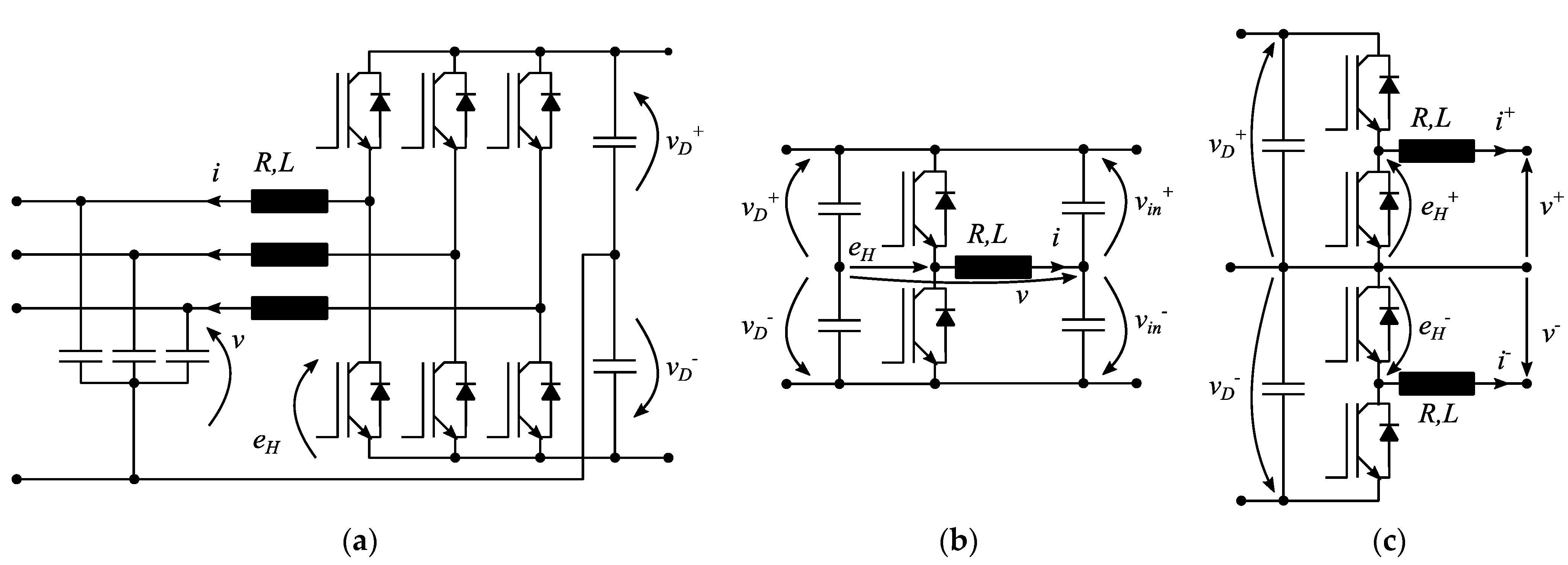
2. Innovative MC Configuration

The proposed MC topology is based on an extension of the converter based on a capacitive internal DC link presented in [5] and further discussed in [11], taking advantage of the enhanced controllability and fault-insensitivity properties of this family of converters. The development of the innovative MC configuration presented here is driven by the rationale of providing a symmetrical structure with a common reference for AC and DC line voltages, thus unifying the AC neutral and DC middle point wires. This is a very significant feature for fault analysis and protection design, as the presence of a common neutral/midpoint wire keeps the fault response consistent among AC and DC ports, which is not the case with standard power converters, nor is it the case with the MC discussed in [5,11]. Thank to this solution, it is possible to have both AC and DC earthing with no functional problems; in addition, for each port, a low-impedance (virtually zero) reclosing path for common-mode currents is present, such that the issues related to common-mode (CM) disturbances discussed in [37,38,39,40] are strongly mitigated.
The proposed MC structure is shown in Figure 1, in general form, including M four-wire AC ports, an internal DC link with an arbitrary number of equilibrators, and N three-wire DC ports. The M four-wire AC ports can be used, indifferently, to connect the MC to an AC source, such as the public AC distribution network, or to fed AC loads. In the latter case, improved reliability can be obtained by integrating storage devices in the MC, realizing UPS functionality. The equilibrators maintain voltage balance between the positive and negative internal DC busbars. Their function is not related to any particular port, hence their locations are purely arbitrary, and their number is defined on the basis of the expected level of unbalance in DC loads. Lastly, the three-wire DC ports have a two-fold scope: first, they allow for the distribution of two voltage levels, which provides greater flexibility for DC loads; second, the distributed neutral wire allows for unified earthing management among AC and DC ports. Moreover, analogous to its two-wire counterpart discussed in [11], the diodes are connected in parallel to the DC port capacitor to prevent the transitory negative voltages that can lead to capacitor damage and a loss of controllability [25].
Thanks to the proposed MC topology here proposed, only three module types are needed, as follows:
  • four-wire AC port module, represented in Figure 2a, including two semiconductors, each required to withstand the full DC link voltage;
  • equilibrator module, represented in Figure 2b, including two semiconductors, each required to withstand the full DC link voltage;
  • three-wire DC port module, represented in Figure 2c, including four semiconductors, each required to withstand one half of the DC link voltage.
As a result, the circuit topology presented in Figure 1 is completely modular, allowing for flexible operation in the ever-changing modern distribution systems.
From a design perspective, since the maximum voltage that DC ports need to withstand is equal to one half of the maximum voltage that AC ports and equilibrators need to withstand, it seems unwise to use equal power electronic building blocks (PEBBs) for all ports. Indeed, due to circuit similarities between the proposed DC port structure and three-level, neutral-point-clamped (NPC) inverter legs, introducing three-level NPC AC ports and equilibrators may be a promising solution to further improve performance and modularity. Nevertheless, the advantages possibly granted by this solution rely on sizing and economic issues, which fall outside the scope of this paper.
From a control perspective, analogous to the control design reported in [11], the overall MC control discussed in detail in the following section comprises two layers: the lower one is constituted by the pseudo-sliding mode modulation of PEBB currents, while the higher control layer, based on an inverse dynamic approach, provides suitable current references for the lower one. This control design approach takes advantage of the stability and robustness properties of sliding mode controllers, the effectiveness of which, in power converter control, is well-known in the literature [59,60]. Additionally, the inverse dynamic technique used for the control higher level, ascribable to the feedback linearization family [61,62] and widely applied in robot manipulator control [63], provides the basis for the design of a suitable sliding manifold and avoids the need for a higher-order sliding mode controller. This general, layered control approach allows for the development of a totally modular control structure, with no need for predetermined port functionalities or a number of ports.

3. Two-Level Control Design

3.1. Lower-Level Pseudo-Sliding Mode Control

The lower-level, pseudo-sliding mode control presented in the following is developed analogously to [11], where this control technique was selected for its superior dynamic performance, robustness, and simplicity. Consider the configuration reported in Figure 2a first and refer to the same figure for symbols. The sliding function (inductance flux error) λ can be defined according to:
λ = L ( i i * ) .
Let fsw be the switching frequency and, consequently, Tsw = 1/fsw be the designed switching period. In addition, assume, as is common for power converter sliding mode control design, that: (a) vD+ > 0 and vD < 0; (b) negligible resistive terms on high-frequency ripple (R << 2πfswL); and (c) vD+ and vD, v and i* being suitable, Lipschitz-continuous functions with spectra are limited to frequencies much lower than the switching frequency fsw.
Referring to Figure 2a and considering the inductor constitutive equation, the relation between the sliding function λ and the ideal switched voltage eH is then formulated as:
d λ d t = e H u e q ,
where the ideal switched voltage eH possible instantaneous values are vD+ and vD. The equivalent voltage is expressed according to:
u e q = v + L d i * d t + R i * .
and represents the equivalent voltage, defined as the ideal continuous value of the discontinuous control variable eH necessary to perform the desired control action [64], equal to the mean value of the switched voltage eH in a sliding condition.
The controllability condition under which a sliding mode can be enforced is determined by considering that, to maintain sliding condition, it is necessary to be able to enforce a positive and negative derivative (2) on the sliding function λ, which results in:
v D < u e q < v D + .
The modulation algorithm used to enforce a sliding mode is based on a dynamic set of slanted thresholds [64], conceived to enforce a sliding mode with a fixed converter switching frequency. This is obtained considering a set of equally spaced time intervals Tk, such that:
T k + 1 = T k + T s w 2 .
In each time interval t ∈ [Tk−1, Tk+1], the resulting control law is
e H = { v D + i f λ < ( v D + u e q ) ( t T k ) v D i f λ > ( v D u e q ) ( t T k ) ,
which realizes the system of slanted thresholds proposed in [64].
Considering now the DC port configuration reported in Figure 2b, and referring to the same figure for symbols, proceeding analogously, the sliding functions (inductance flux error) λ+, λ can be defined as
λ + = L ( i + i + * ) , λ = L ( i i * ) ,
and the relation between the sliding functions λ+, λ and the ideal switched voltage eH+, eH is formulated as
d λ + d t = e H + u e q + , d λ d t = e H u e q .
The ideal switched voltage eH+ possible instantaneous values are 0 and vD+, while the ideal switched voltage eH possible instantaneous values are 0 and vD. The equivalent voltages are expressed according to:
u e q + = v + + L d i + * d t + R i + * , u e q = v + L d i * d t + R i * .
Consequently, controllability conditions, separately for each half of the module, result in
0 < u e q + < v D + , v D < u e q < 0 ,
and, in each time interval, the resulting control law is:
e H + = { v D + i f λ + < ( v D + u e q + ) ( t T k ) 0 i f λ + > ( u e q + ) ( t T k ) , e H = { 0 i f λ < ( v D u e q ) ( t T k ) v D i f λ > ( u e q ) ( t T k ) .

3.2. Higher-Level Inverse Dynamic Control

The higher-level control is based on an inverse dynamic approach and relies on maintaining power balances to control internal and external voltages. For the sake of clarity, consider, with no loss of generality, an example case comprising N = 6 ports, as shown in Figure 3, where port 1 is connected to an AC grid, which acts as an external power source; port 2 is connected to storage devices, which allows for high dynamic performance to be maintained regardless of grid dynamics, and realizes UPS functionality; port 3 is connected to an AC load; port 4 is connected to a PV source; ports 5 and 6 are connected to DC loads. Control-wise, the PV port is treated as a load since it requires a predetermined voltage obtained from an MPPT algorithm. Note that, due to the modular topology and control design concept, developing the control design for the present case study is a non-restrictive assumption, and it can be easily generalized to any number of ports. In particular, the control equations presented in the following enable the realization of voltage-controlled ports, power-controlled ports or current-controlled ports, covering all the functionalities usually required for distribution system applications and realizing a fully modular control layer where all ports performing the same functionality are controlled by the same control equation, while the centralized control is only required to manage the different power sources.
Let us consider voltage control first. Since the proposed MC is required to maintain the power balance among AC and DC ports, which may each have a different voltage level, the control is formulated in terms of port powers. Current references for the modulation algorithm are successively obtained as functions of reference powers and measured port voltages. Note that, as far as three-phase ports are concerned, the control equations are formulated in terms of a space vector for clarity and compactness; furthermore, in the following, the zero component is neglected, which implies that the converter produces balanced voltages. However, zero-component control can be realized with the same approach, if necessary.
According to the inverse dynamic control principles [63], let us define the voltage tracking error εi at the i-th port as:
ε i = v i * v i i = 3 , ε i + = v i + * v i + ε i = v i * v i } i [ 4 ; 6 ] ,
and the dynamic voltage error equation as:
η i = f ( ε i , ( ε i ) d t , d ε i d t , , d n ε i d t n ) .
For each port, at capacitor terminals, the power balance can be formulated as:
S i = d d t [ 1 2 C i ( 2 3 | v i | ) 2 ] + 3 2 v i i ¯ l o a d i * i = 3 , P i + = d d t [ 1 2 C i ( v i + ) 2 ] + v i + i l o a d i + P i = d d t [ 1 2 C i ( v i + ) 2 ] + v i i l o a d i } i [ 4 ; 6 ] ,
being iload i the current absorbed by the load connected to the i-th port. Considering (14), by tedious yet simple calculus, the derivatives of the tracking error are obtained as:
d d t ( v i * v i ) = d d t v i * + j ω v i + 1 C i ( i l o a d i 2 3 S ¯ i v ¯ i ) i = 3 , d d t ( v i + * v i + ) = d d t v i + * + 1 C i ( i l o a d i + P i + v i + ) d d t ( v i * v i ) = d d t v i * + 1 C i ( i l o a d i P i v i ) } i = [ 4 ; 6 ] .
The dynamic voltage error equation should contain, in addition to the tracking error itself, the tracking error integral to enforce null static error, and tracking error derivatives up to the order necessary to obtain explicit dependence of the controlled variable εi from the control variable Si or Pi. From (15), it is observed that only one derivative term is needed, so that the dynamic voltage error equations are defined as:
η i = ( v i * v i ) + K 1 d d t ( v i * v i ) + 1 K 2 ( v i * v i ) d t i = 3 , η i + = ( v i + * v i + ) + K 1 d d t ( v i + * v i ) + 1 K 2 ( v i + * v i + ) d t η i = ( v i * v i ) + K 1 d d t ( v i * v i ) + 1 K 2 ( v i * v i ) d t } i [ 4 ; 6 ] ,
where K1, K2 are time constants to be assigned to obtain the desired damping and dynamic response.
Consider now the system in a sliding condition, so that ii = ii*, and, as a consequence, Pi = Pi*. By substituting (15) in (16), it is possible to obtain the port reference power:
S i * = 3 2 v i [ ( C i d d t v ¯ i * + j ω C i v ¯ i + i ¯ l o a d i ) + g 1 i ( v ¯ i * v ¯ i ) + g 2 i ( v ¯ i * v ¯ i ) d t ] , i = 3 , P i + * = v i + [ C i d d t v i + * + i l o a d i + * + g 1 i ( v i + * v i + ) + g 2 i ( v i + * v i + ) d t ] P i * = v i [ C i d d t v i * + i l o a d i * + g 1 i ( v i * v i ) + g 2 i ( v i * v i ) d t ] } , i = [ 4 ; 6 ] ,
where g1 i = Ci/K1, g2 i = Ci/(K1K2). Note that (17) provides the reference power that realizes the control of the external port voltages with dynamics assigned by coefficients g1 i, g2 i. Furthermore, one can note that (17) is formally equivalent to a PI regulator with feed-forward/compensation terms: in (17), between square brackets, the first term between round brackets can be considered a feed-forward/compensation term, while the second and third terms are, respectively, proportional and integral terms.
After the control of v3, v4, v5, v6 is defined, control references for ports 1 and 2 are designed in terms of port powers with the aim of controlling the MC internal bus voltage. In these regards, the global reference power that must be absorbed from ports 1 and 2 to maintain the internal bus voltage is defined as Pg* = P1* + P2*. The internal DC bus voltage can hence be controlled by considering the power balance at the internal DC bus terminals, which, observing that the internal bus depicted in Figure 3 includes six couples of series-connected capacitors, results in:
P g = d d t [ 1 2 ( 6 C i n 2 ) v i n 2 ] + 3 2 Re { v 3 i ¯ 3 } + i = 4 6 ( v i + i i + + v i i i ) ,
where vin = vin+ - vin represents the internal bus pole-to-pole voltage. By means of the same procedure used to obtain (17), the control law for the DC bus voltage is obtained from (18), resulting in:
P g * = v i n [ 6 2 C i n d d t v i n * + g 1 i n ( v i n * v i n ) + g 2 i n ( v i n * v i n ) d t ] + + Re { S 3 * } + i = 4 6 ( P i + * + P i * ) ,
where g1 in = (6/2)Cin/K1, g2 in = (6/2)Cin/(K1K2). Note that, similar to the control of external port voltages realized by (17), (19) provides the reference power to control of the internal bus voltage with dynamics assigned by coefficients g1 in, g2 in, and is formally equivalent to a PI regulator with feed-forward/compensation terms.
Power Pg* must be split into ports 1 and 2 by means of a suitable logic, such as:
{ P 1 * = β 1 P g * P 2 * = β 2 P g * , β 1 + β 2 = 1 ,
where the terms βi can be constants, functions, or references obtained from an upper-level supervisory control.
Lastly, for the considered three-wire configuration, it is necessary to introduce the equilibrator control to maintain voltage balance. Define voltage unbalance as:
v b a l = v i n + + v i n ,
and recognizing that, in the present topology, only DC ports can introduce voltage unbalances, the unbalance power is consequently defined as:
P u n = i = 4 6 ( P i + * P i * ) ,
such that it is possible to introduce a power balance equation similar to (18) for the internal bus. Observing that the internal bus depicted in Figure 3 includes six couples of capacitors, parallel-connected with respect to voltage balancing, the desired power balance equation results in:
P b a l = d d t [ 1 2 ( 12 C i n ) v b a l 2 ] P u n .
Considering (23) and recognizing that vbal*= 0, the reference balancing power is obtained as
P b a l * = v i n [ g b 1 v b a l + g b 2 v b a l d t ] P u n ,
where gains are defined as gb1 = (12Cin)/(K1), gb2 = (12Cin)/(K1K2). If more than one equilibrator is present, balancing power can be treated, similarly to (20), by means of a number of suitable, unity-sum coefficients.
Lastly, current references for each port are obtained from power references as:
i i * = 2 3 P i * v ¯ i i = 1 ,
i i * = P i * v i i = 2 ,
i i * = 2 3 S ¯ i * v ¯ i i = 3 ,
i i + * = P i + * v i + i i * = P i * v i } i [ 4 , 6 ] ,
i b a l * = P b a l * v i n .
Note that (25), being aimed at controlling the internal bus voltage through (19), includes active power only. Clearly, a certain reactive power can be also exchanged if necessary, resulting in a control equation similar to (27). In more general cases, (25) and (26) are valid for, respectively, AC and DC ports connected to controllable energy sources, while (27) and (28) are valid, respectively, for AC and DC ports connected to loads or non-controllable energy sources (i.e., PV plants). Each current reference magnitude should also be limited to a predetermined value, depending on the semiconductors’ maximum current, in order to avoid possible issues in cases of external faults.

4. Fault Analysis

For the proposed MC, it is of interest to evaluate the effect of an external fault, of a fault on the internal DC link, and to briefly discuss the proposed MC properties in terms of fault management derived by the proposed control design. Each of these aspects is addressed in the following subsections.

4.1. External Fault Analysis

For the considered MC converter, it is of interest to consider external faults on both AC and DC ports. These faults have a different effect on converter operation, depending on port functionality. If the faulted port is connected to a controllable energy source, the voltage reduction due to the fault makes it impossible to transfer the power required by higher-level control without exceeding the converter current limits. As a consequence, the power balance in the internal bus is momentarily lost, resulting in a voltage deviation, which will then be compensated by the converter control by acting on the power exchange on the healthy ports. If the faulted port is connected to a load or non-controllable energy source, then the fault will make it impossible to maintain the correct voltage without exceeding the converter current limits. As a consequence, voltage regulation is lost.
In both cases, however, the converter current control is maintained over the whole transient, ensuring the converter operation’s safety. This is obtained by virtue of the stability properties of sliding mode controllers [59,60,61,62]. Indeed, the condition that allows the sliding condition to be reached in finite time and maintains sliding condition thereafter is expressed by (4) for each PEBB realizing an AC port, and by (10) for any module realizing a DC port. During normal operating conditions, (4) and (10) are usually satisfied for a correctly designed system under a non-restrictive hypothesis, namely, when capacitor voltages and current references are ascribable to suitable, limited, Lipschitz-continuous functions. This is taken for granted in the case of capacitor voltages, yet two significant exceptions must be considered for currents, namely, external faults and load step-changes, as the line current iload i at the i-th port appears in power references (17). Between these two occurrences, the fault is of course the worst case, as not only can an uncontrolled transient be experienced by the system, but it may also not be possible to regulate the port voltage or exchange the required power after the transient is extinguished, depending on the value of the fault impedance. As a worst case, let us hence consider the case of a bolted fault.
For a DC port, let us consider, with no loss of generality, a bolted pole-to-midpoint fault. A pole-to-pole fault can be treated similarly due to the converter’s symmetric structure. Additionally, let us neglect, in the mathematical analysis, the diodes connected in parallel to each DC port output capacitor, which as mentioned, are used to prevent the port voltage from changing its sign, which would result in loss of controllability and possible converter damage.
In case of a bolted pole-to-midpoint fault, the i-th DC port, the fault causes an uncontrollable current in the faulted line as the converter output capacitor rapidly discharges through the line and the fault. Denote the line resistance and inductance as Rline i and Lline i, respectively, and assume, for simplicity of notation, that the fault occurs at time t = 0, the MC fault current contribution can be calculated as a simple second order RLC transient. With reference to Figure 3 for variables, the MC DC fault current contribution is generally obtained as:
i l o a d i ( t ) = H 1 i e s 1 i t + H 2 i e s 2 i t + I M a x i ,
where H1i, H2i are constants depending on the circuit initial conditions, s1i, s2i are constants defined as:
{ s 1 i = α + α 2 ω 0 2 s 2 i = α α 2 ω 0 2
where α = Rline i/(2Lline i) and ω0 = 1/√(Lline iCi) and IMax i is the constant converter current limit set by the converter control, as mentioned at the end of Section 3.2, which is to be considered the fault steady-state value and, hence, the transient steady-state solution.
When denoting the initial condition for the converter fault current contribution as follows:
{ i l o a d i ( 0 ) = I 0 d d t i l o a d i ( 0 ) = v i ( 0 ) R l i n e i i l o a d i ( 0 ) L l i n e i ,
the constants H1i, H2i are obtained as:
{ H 1 i = v i ( 0 ) R l i n e i i l o a d i ( 0 ) ( I M a x i i l o a d i ( 0 ) ) L l i n e i s 2 i L l i n e i ( s 1 i s 2 i ) H 2 i = v i ( 0 ) R l i n e i i l o a d i ( 0 ) ( I M a x i i l o a d i ( 0 ) ) L l i n e i s 1 i L l i n e i ( s 1 i s 2 i )
Equations (30)–(33) characterize the fault response of a DC port, but can be easily adapted to AC ports, for each phase, as follows. In this case, (30) and (31) can be used as is, which is the general solution for an RLC circuit transient. The term IMax i appearing in (30) maintains the same meaning, but must be considered as a sinusoidal function (IMax i (t) = IMax i sin(ωt + φ)), the amplitude of which is equal to the maximum current contribution set by the converter control. The initial conditions are again defined by (32), yet the solution for the constants H1i, H2i must now consider the sinusoidal steady-state solution, resulting in:
{ H 1 i = v i ( 0 ) R l i n e i i l o a d i ( 0 ) ( I M a x i ( 0 ) i l o a d i ( 0 ) ) L l i n e i s 2 i L l i n e i d d t I max i ( 0 ) L l i n e i ( s 1 i s 2 i ) H 2 i = v i ( 0 ) R l i n e i i l o a d i ( 0 ) ( I M a x i ( 0 ) i l o a d i ( 0 ) ) L l i n e i s 1 i L l i n e i d d t I max i ( 0 ) L l i n e i ( s 1 i s 2 i )
However, as is also the case with bolted faults, current references can be approximated with a Lipschitz-continuous function, except from a limited time. Indeed, it is straightforward to prove that the fault current (30) can exhibit, during the transient phase only, a time derivative higher than the one enforced by the converter current control, the upper bound of which, neglecting resistive terms and external voltage, can be approximated as:
d i m a x d t = v D L
As a consequence, during the transient phase, voltage regulation and power exchange may not be performed correctly.
However, after the transient is extinguished, (4) and (10) are satisfied for any port. As a consequence, while the potential to control the port voltage/power depends on the fault impedance value, the current sliding condition is lost at the instant corresponding to the step-change, but then reached again in finite time. As a consequence, a pole-to-pole fault on one port does not violate (4) and (10) except from a very limited time, so that output currents are always kept under control and no faults on one output port can affect other ports or the internal DC bus. Additionally, under pole-to-pole fault conditions, which (4) and (10) have satisfied for voltage values smaller than the rated ones, the converter current control is maintained, so that the converter can limit the fault current to a predetermined, bearable value, such that the converter is self-protected during faults. In these regards, the most obvious choice is to keep the current constant and equal to its maximum value until the fault is resolved and voltage can be recovered. If the fault is not resolved in a predetermined time (reasonably, a few seconds) the current reference is set to zero for safety reasons. Nevertheless, if the converter control is integrated in the system protection, any fault current value can be selected.
When considering pole-to-earth faults, different problems arise depending on the state of active parts towards earth. Usually, low-voltage distribution systems are not exercised when isolated from earth, except in special applications or in regions where effective earthing is problematic, such that it is of interest to briefly consider the possible earthing solution for a system including the considered MC. With reference to Figure 3, the presence of the distributed neutral wire/DC middle point for all ports suggests that the neutral wire should be directly earthed, as is usual for AC systems. In this case, both for AC and DC systems, the proposed three-wire converter allows for correct system operation and earth fault clearance, since earth faults are equivalent to pole-to-pole faults and the considerations presented in the previous paragraph apply.
Furthermore, in hybrid distribution systems, the proposed converter topology forces the state of active parts towards earth of each section to be the same, unless isolated ports are introduced. This greatly simplifies the definition of earthing policies with respect to systems with many isolated sections and avoids unnecessary cascaded conversion stages. A significant advantage is also gained if the AC port is connected to a load or load feeder and if the AC port is connected to an AC power source. If the AC port is feeding loads, this implies that it is possible to use either a TT or TN earthing scheme, which was not possible with the two-wire MCs considered in [11], and simplifies the evaluation of electrical safety issues. If, on the contrary, the AC port is connected to an AC power source, this does not require an isolation transformer, even if a transformer is already present (i.e., MV/LV transformer), to isolate the star centre from earth. Furthermore, problems similar to the ones discussed in [40] cannot arise due to the symmetry of the considered MC.
To complete the discussion on earth faults, a detailed analysis of this configuration in earth-isolated systems should be performed. However, this can be difficult since it is necessary to evaluate parasitic system parameters, which are difficult to assess and very case-dependent. Even though a detailed analysis of earth faults lies outside the purposes of this paper, the presented considerations clarify that, in the case of a directly earthed neutral wire, correct operation can be achieved, and fault clearance is possible both for pole-to-pole and pole-to-earth faults. Furthermore, AC and DC ports can be freely introduced with no need for specific adaptations and with no risks of common-mode voltage-related issues.

4.2. Internal Fault Analysis

As previously mentioned, the condition that allows the sliding condition to be reached in finite time and maintains sliding condition thereafter is expressed by (4) for each PEBB realizing an AC port or equilibrator, and by (10) for any module realizing a DC port. These conditions are usually satisfied for a correctly designed system under a non-restrictive hypothesis, which in this case can be reduced to the capacitor voltages and current references being ascribable to suitable, limited, Lipschitz-continuous functions.
In case of a pole-to-pole and, possibly, a pole-to-earth fault on the internal DC bus, the internal voltage will be reduced, possibly down to zero, depending on the fault impedance values. As the external voltages are initially non-null, both (4) and (10) are violated, and uncontrolled currents flow through free-wheeling diodes in all PEBBs, which may result in damage. This occurrence cannot be avoided by any control algorithm, but its probability can be considered very low as the internal DC link can be easily included in a switchboard.

5. Simulation Results

Simulations were performed to substantiate the considered topology and related controls. Load and source parameters are presented in Table 1.
For compactness, the positive and negative halves of each port are identified with a plus and minus (e.g., 5+ represents the electric port constituted by the fifth port positive pole and middle point, while 5− represents the electric port constituted by the fifth port middle point and negative pole). Converter and control parameters are shown in Table 2. Four events were considered in order to show the control’s effectiveness in managing abrupt load variations, main grid failure, and external faults. Each of these events is discussed separately in the following subsections.

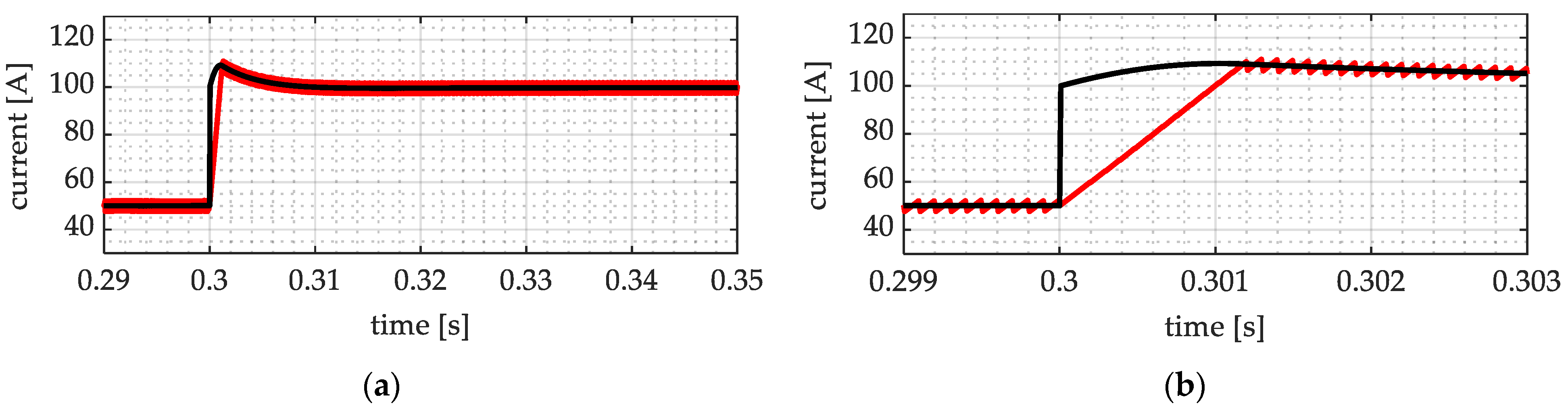
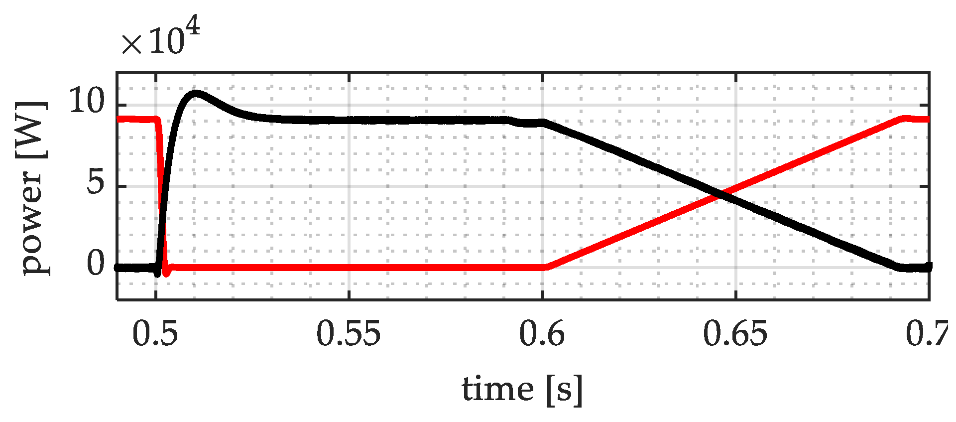
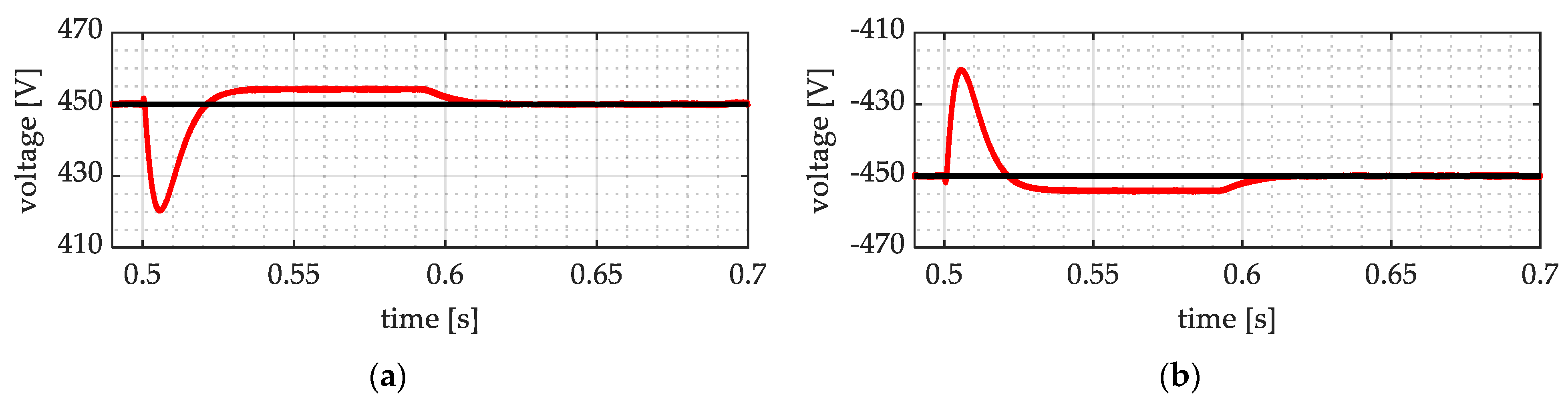
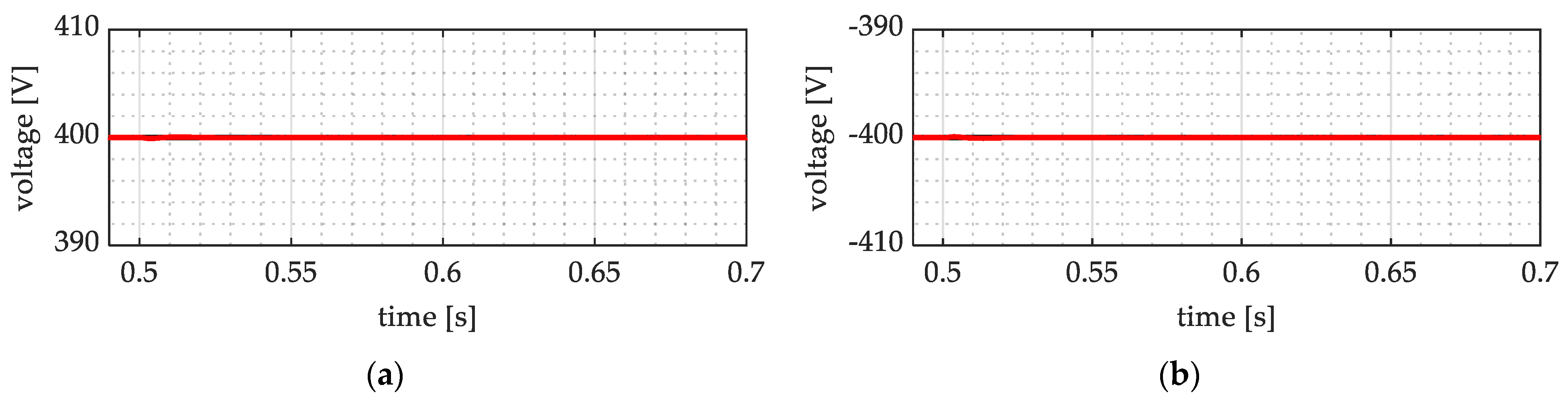
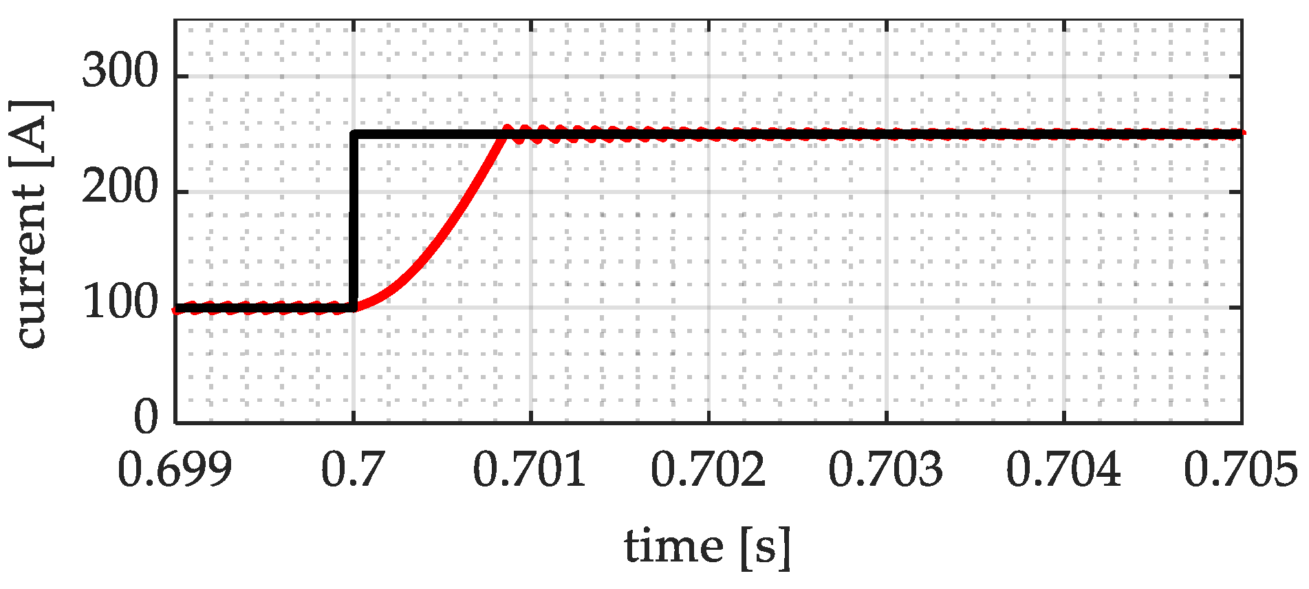
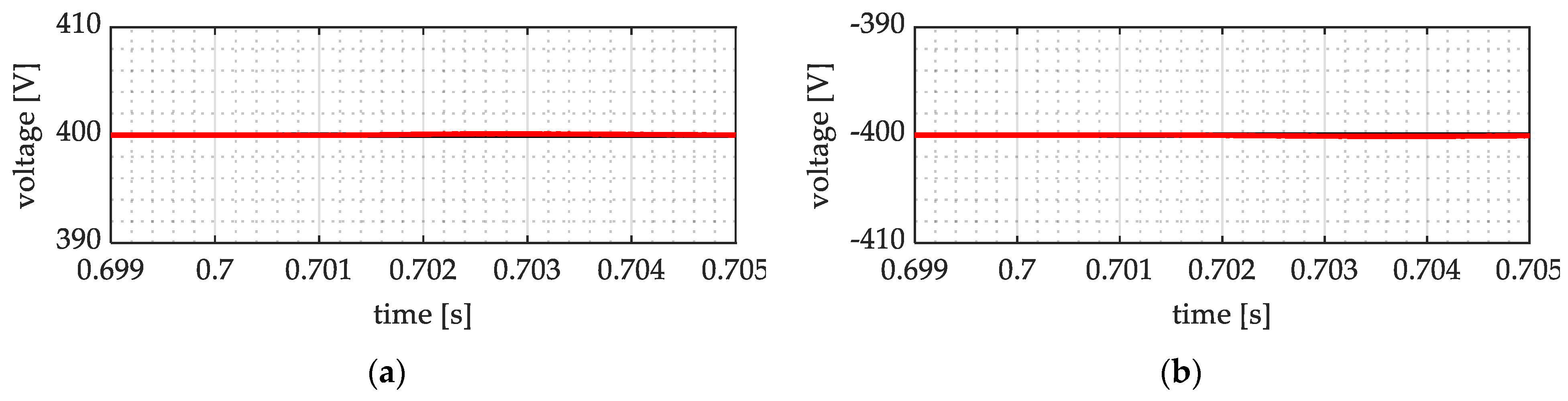
5.1. DC Load Asymmetrical Step-Change

The first considered event is a DC load asymmetrical step-change from 20 kW to 40 kW on port 5+, occurring at time 0.3 s. The corresponding voltages v5+, v5 are reported in Figure 4a,b. Currents i5+ is reported in Figure 5a,b. One can notice that voltage and current transients exhibit the expected behaviour: initially, the load step-change causes a fast change in the current reference, which causes a violation of controllability condition (10) and, consequently, a temporary loss of sliding condition. By roughly one millisecond, condition (10) is satisfied again, reaching phase is established, and sliding condition is enforced. Once sliding condition is reached, voltage error is forced to zero following the assigned dynamic, such that nominal voltage is restored in about 25 ms (≅five time constants). In addition, one can note that the voltage of the negative half on port five is not affected by any perturbation (Figure 4b).
To verify the effectiveness of the equilibrator control in balancing internal voltages, the internal voltages vin+ and vin are reported in Figure 6a and Figure 6b, respectively. One can observe that, except from a negligible transient in correspondence of the DC load step change, voltages track their respective references correctly and no voltage unbalance due to load unbalance is present.

5.2. AC Load Step-Change
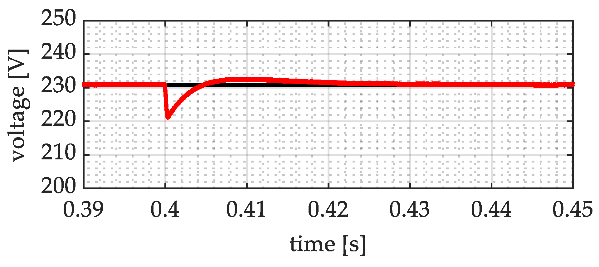
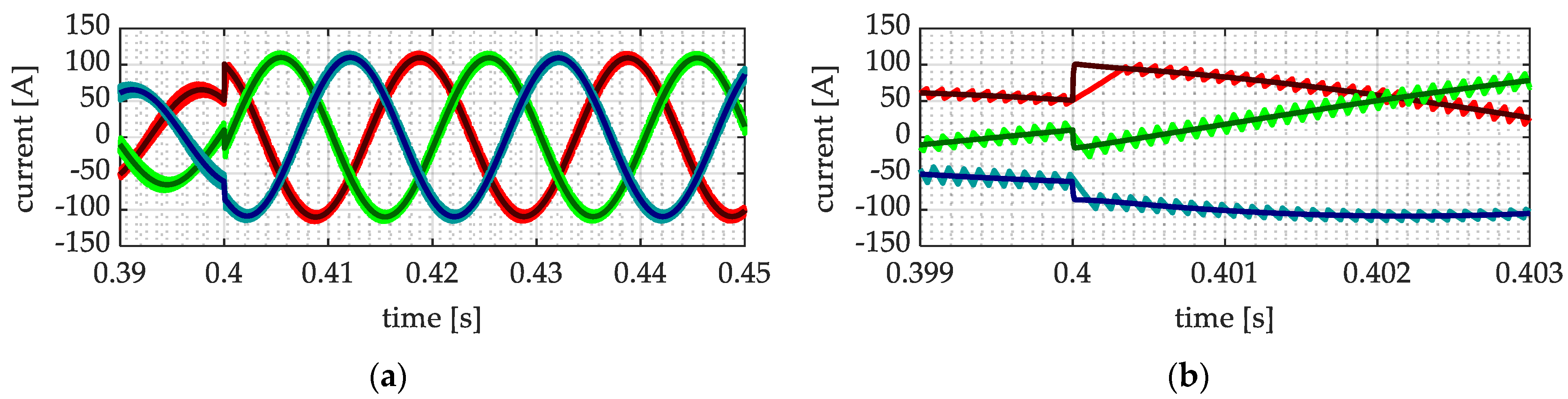
The second considered event is an AC load step-change from 25 kW to 50 kW on port 3, occurring at 0.4 s. Since a small, few-milliseconds-long transient on three phase variables can be hardly appreciated, the port 3 voltage module is shown in Figure 7. On the contrary, to appreciate the current tracking effectiveness during fast transients, phase currents are shown in Figure 8a,b. The same considerations reported for the DC load step-change apply, with particular reference to voltage tracking dynamics, momentary loss of the sliding condition, reaching phase, and re-enforcement of sliding condition. In addition, it can be noted that, since the difference between AC voltage and internal DC link voltage is larger than the difference between DC port voltages and internal DC link voltage, the maximum current derivative that can be impressed by the converter on the AC port currents is higher, resulting in a shorter reaching phase (Figure 8b).

5.3. AC Mains Fault

The third considered event is a fault affecting the main AC grid, connected to port 1, from 0.5 s to 0.6 s. The power absorbed from the available sources is shown in Figure 9, while the internal bus positive and negative pole voltages are shown in Figure 10a and Figure 10b, respectively.
Port five voltages v5+, v5 are shown in Figure 11a and Figure 11b, respectively. It can be seen that the batteries correctly operate to provide the requested power, such that the internal bus voltage experience a reasonable transient; load voltages (Figure 11a,b) are unaffected by the main grid outage. This is consistent with the considerations discussed in Section 4 in which only the module directly connected to the grid loses its sliding condition due to the fault so that the only voltage affected by any disturbance is the internal voltage, as it is controlled by that module. Consequently, the internal voltage is strictly controlled, with a perturbation during the disconnection from the grid, which does not have an impact on load voltages, and creates a negligible one during the reconnection.

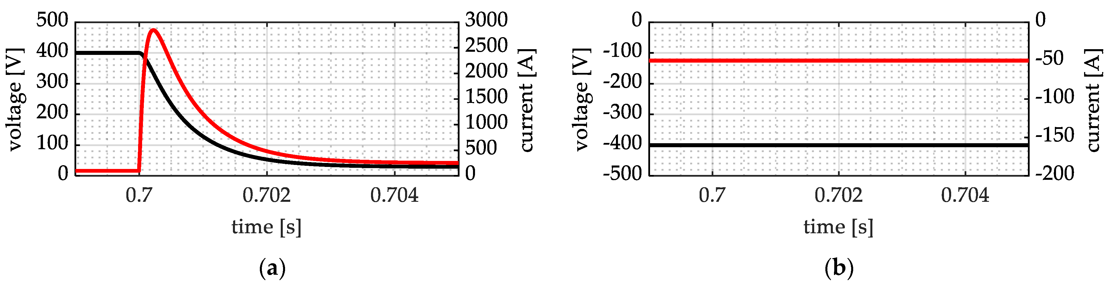
5.4. DC Port External Fault

The fourth considered event is an external fault, namely, a bolted pole-to-midpoint fault on port 6+, occurring at time 0.7 s. The corresponding voltage v6+ and current i+load 6 are shown in Figure 12a, while port 6 voltage v6 and current iload 6 are shown in Figure 12b. Current i6+ is shown in Figure 13; and port 5 voltages v5+, v5 are shown in Figure 14a and 14b, respectively. It can be seen that, even though an uncontrolled fault current is experienced from the line/load, the current supplied by the converter remains controlled during the whole fault and is correctly limited to a predetermined value. Furthermore, the healthy half of the faulted port and the other healthy port voltages are unaffected by the fault: this is again consistent with Section 4, in that there is no reason for those ports to lose the sliding condition.
As per the presented results, the considered MC exhibits robustness properties with respect to external faults, including power supply failure/perturbations, in that (4) and (10) ensure that current controllability is maintained. The presented results reinforce the consideration that the considered MC topology is particularly suited for centralized architectures, where the possibility to have a protected internal DC bus reduces the probability of internal faults. In this case, it is possible to take advantage of the external fault insensitivity of the proposed converter, which can ensure fault clearance in cases of both pole-to-pole and pole-to-earth faults.

6. Conclusions

While MCs have been widely studied for a wide range of applications, their application to LVDC distribution systems is worthy of further discussion due to three main issues. First, a modular topology seems to be of the utmost importance for distribution systems application, but this issue is often overlooked. Second, electronic power converters introduce a discontinuity in the neutral wire and earthing management of hybrid AC/DC systems, which is usually addressed by introducing galvanically isolated converters, resulting in unnecessary cascaded conversion stages and complex earthing management. Third, the possibility of exploiting converter control capabilities to mitigate fault effects is scarcely explored.
In order to overcome the issues of limited modularity, interference with the state of active parts towards earth, and controllability in fault conditions, a new MC for hybrid distribution systems is introduced in this paper. This introduces two main contributions for MC applications: first, a new MC topology is introduced, and an innovative control structure based on two control layers is proposed, including a pseudo-sliding mode controller directly acting on semiconductor switching, and an inverse dynamic control approach applied to voltage controller design. Second, to overcome the lack of effective DC circuit breakers, which represents a traditional issue in DC systems, the proposed control approach is developed with particular attention to current controllability during faults, and the proposed MC properties are investigated with respect to this issue.
The presented results highlight that the proposed MC converter and its control algorithms can effectively manage different loads, providing a high-quality power supply not affected by abrupt load variations or faults on other ports. Additionally, the proposed MC was shown to behave as a fault-tolerant power hub, and can be integrated in hybrid distribution systems protection algorithms without the traditional limitations of power converters that may suffer damage from grid faults.

Author Contributions

Conceptualization, S.N. and G.U.; methodology, S.N. and G.U.; software, S.N.; validation, S.N., G.U. and R.S.F.; formal analysis, S.N.; investigation, S.N. and G.U.; resources, R.S.F.; data curation, S.N.; writing—original draft preparation, S.N. and G.U.; writing—review and editing, S.N. and R.S.F.; visualization, S.N. and R.S.F.; supervision, R.S.F.; project administration, R.S.F.; funding acquisition, R.S.F. All authors have read and agreed to the published version of the manuscript.

Funding

This research received no external funding.

Institutional Review Board Statement

Not applicable.

Informed Consent Statement

Not applicable.

Data Availability Statement

The original contributions presented in the study are included in the article, further inquiries can be directed to the corresponding author.

Conflicts of Interest

Author Giovanni Ubezio is a collaborator of the company E.C. & C. srl. The remaining authors declare that the research was conducted in the absence of any commercial or financial relationships that could be construed as a potential conflict of interest.

References

  1. Khosrogorji, S.; Ahmadian, M.; Torkaman, H. Multi-input DC/DC converters in connection with distributed generation units—A review. Renew. Sustain. Energy Rev. 2016, 66, 360–379. [Google Scholar] [CrossRef]
  2. Rehman, Z.; Al-Bahaly, I.; Mukhopadhyay, S. Multiinput DC–DC converters in renewable energy applications—An overview. Renew. Sustain. Energy Rev. 2015, 41, 521–539. [Google Scholar] [CrossRef]
  3. Zhang, N.; Sutanto, D.; Muttaqi, K.M. A review of topologies of three-port DC–DC converters for the integration of renewable energy and energy storage system. Renew. Sustain. Energy Rev. 2016, 56, 388–401. [Google Scholar] [CrossRef]
  4. Veena, P.; Indragandhi, V.; Jeyabharath, R.; Subramaniyaswamy, V. Review of grid integration schemes for renewable power generation system. Renew. Sustain. Energy Rev. 2014, 34, 628–641. [Google Scholar] [CrossRef]
  5. Jiang, W.; Fahimi, B. Multiport Power Electronic Interface—Concept, Modeling, and Design. IEEE Trans. Power Electron. 2011, 26, 1890–1900. [Google Scholar] [CrossRef]
  6. Shamsi, P.; Fahimi, B. Dynamic Behavior of Multiport Power Electronic Interface Under Source/Load Disturbances. IEEE Trans. Ind. Electron. 2013, 60, 4500–4511. [Google Scholar] [CrossRef]
  7. Corti, M.; Tironi, E.; Ubezio, G. Multi-port converters in smart grids: Protection selectivity. In Proceedings of the 2016 International Symposium on Power Electronics, Electrical Drives, Automation and Motion (SPEEDAM), Anacapri, Italy, 22–24 June 2016; pp. 143–149. [Google Scholar]
  8. Danyali, S.; Niapour, S.A.K.H.M.; Hosseini, S.H.; Gharehpetian, G.B.; Sabahi, M. New Single-Stage Single-Phase Three-Input DC-AC Boost Converter for Stand-Alone Hybrid PV/FC/UC Systems. Electr. Power Syst. Res. 2015, 127, 1–12. [Google Scholar] [CrossRef]
  9. Faraji, R.; Adib, E.; Farzanehfard, H. Soft-switched non-isolated high step-up multi-port DC-DC converter for hybrid energy system with minimum number of switches. Int. J. Electr. Power Energy Syst. 2019, 106, 511–519. [Google Scholar] [CrossRef]
  10. Negri, S.; Tironi, E.; Ubezio, G. Local DC Distribution System in Presence of RES and Storage Devices: Multiport Converters Application. In Proceedings of the 2018 IEEE International Conference on Environment and Electrical Engineering and 2018 IEEE Industrial and Commercial Power Systems Europe (EEEIC/I&CPS Europe), Palermo, Italy, 12–15 June 2018; pp. 1–8. [Google Scholar]
  11. Negri, S.; Tironi, E.; Superti-Furga, G.; Ubezio, G. Control and Fault Analysis of Multiport Converters for Low Voltage DC Distribution Systems. Int. J. Electr. Power Energy Syst. 2021, 124, 106335. [Google Scholar] [CrossRef]
  12. Zhao, C.; Round, S.D.; Kolar, J.W. An Isolated Three-Port Bidirectional DC-DC Converter with Decoupled Power Flow Management. IEEE Trans. Power Electron. 2008, 23, 2443–2453. [Google Scholar] [CrossRef]
  13. Schäfer, J.; Bortis, D.; Kolar, J.W. Multi-port multi-cell DC/DC converter topology for electric vehicle’s power distribution networks. In Proceedings of the 2017 IEEE 18th Workshop on Control and Modeling for Power Electronics (COMPEL), Stanford, CA, USA, 9–12 July 2017; pp. 1–9. [Google Scholar]
  14. Li, W.; Xiao, J.; Zhao, Y.; He, X. PWM Plus Phase Angle Shift (PPAS) Control Scheme for Combined Multiport DC/DC Converters. IEEE Trans. Power Electron. 2012, 27, 1479–1489. [Google Scholar] [CrossRef]
  15. Itoh, K.; Ishigaki, M.; Yanagizawa, N.; Tomura, S.; Umeno, T. Analysis and Design of a Multiport Converter Using a Magnetic Coupling Inductor Technique. IEEE Trans. Ind. Appl. 2015, 51, 1713–1721. [Google Scholar] [CrossRef]
  16. Wu, H.; Sun, K.; Zhu, L.; Xing, Y. An Interleaved Half-Bridge Three-Port Converter with Enhanced Power Transfer Capability Using Three-Leg Rectifier for Renewable Energy Applications. IEEE J. Emerg. Sel. Top. Power Electron. 2016, 4, 606–616. [Google Scholar] [CrossRef]
  17. Kumar, L.; Jain, S. A multiple source DC/DC converter topology. Int. J. Electr. Power Energy Syst. 2013, 51, 278–291. [Google Scholar] [CrossRef]
  18. Zhu, H.; Zhang, D.; Athab, H.S.; Wu, B.; Gu, Y. PV Isolated Three-Port Converter and Energy-Balancing Control Method for PV-Battery Power Supply Applications. IEEE Trans. Ind. Electron. 2015, 62, 3595–3606. [Google Scholar] [CrossRef]
  19. Jakka, V.N.S.R.; Shukla, A.; Demetriades, G.D. Dual-Transformer-Based Asymmetrical Triple-Port Active Bridge (DT-ATAB) Isolated DC–DC Converter. IEEE Trans. Ind. Electron. 2017, 64, 4549–4560. [Google Scholar] [CrossRef]
  20. Qian, Z.; Abdel-Rahman, O.; Batarseh, I. An Integrated Four-Port DC/DC Converter for Renewable Energy Applications. IEEE Trans. Power Electron. 2010, 25, 1877–1887. [Google Scholar] [CrossRef]
  21. Wu, H.; Zhang, J.; Xing, Y. A Family of Multiport Buck–Boost Converters Based on DC-Link-Inductors (DLIs). IEEE Trans. Power Electron. 2015, 30, 735–746. [Google Scholar] [CrossRef]
  22. Tironi, E.; Corti, M.; Ubezio, G. A novel approach in multi-port DC/DC converter control. In Proceedings of the 2015 International Conference on Clean Electrical Power (ICCEP), Taormina, Italy, 16–18 June 2015; pp. 48–54. [Google Scholar]
  23. Corti, M.; Tironi, E.; Ubezio, G. DC Networks Including Multiport DC/DC Converters: Fault Analysis. IEEE Trans. Ind. Appl. 2016, 52, 3655–3662. [Google Scholar] [CrossRef]
  24. Wu, H.; Xu, P.; Hu, H.; Zhou, Z.; Xing, Y. Multiport Converters Based on Integration of Full-Bridge and Bidirectional DC–DC Topologies for Renewable Generation Systems. IEEE Trans. Ind. Electron. 2014, 61, 856–869. [Google Scholar] [CrossRef]
  25. Negri, S.; Tironi, E.; Ubezio, G. Zonal DC Distribution System based on Multiport Converters: Fault Analysis and Protection Design. In Proceedings of the 2019 IEEE Milan PowerTech, Milan, Italy, 23–27 June 2019; pp. 1–6. [Google Scholar]
  26. Negri, S.; Giani, F.; Blasuttigh, N.; Pavan, A.M.; Mellit, A.; Tironi, E. Combined model predictive control and ANN-based forecasters for jointly acting renewable self-consumers: An environmental and economical evaluation. Renew. Energy 2022, 198, 440–454. [Google Scholar] [CrossRef]
  27. Negri, S.; Tironi, E.; Danna, D.S. Integrated control strategy for islanded operation in smart grids: Virtual inertia and ancillary services. In Proceedings of the 2017 IEEE International Conference on Environment and Electrical Engineering and 2017 IEEE Industrial and Commercial Power Systems Europe (EEEIC/I&CPS Europe), Milan, Italy, 6–9 June 2017; pp. 1–6. [Google Scholar]
  28. La Bella, A.; Negri, S.; Scattolini, R.; Tironi, E. A Two-Layer Control Architecture for Islanded AC Microgrids with Storage Devices. In Proceedings of the 2018 IEEE Conference on Control Technology and Applications (CCTA), Copenhagen, Denmark, 21–24 August 2018; pp. 1421–1426. [Google Scholar]
  29. Ganjavi, A.; Ghoreishy, H.; Ahmad, A.A. A Novel Single-Input Dual-Output Three-Level DC–DC Converter. IEEE Trans. Ind. Electron. 2018, 65, 8101–8111. [Google Scholar] [CrossRef]
  30. Wang, Z.; Li, H. An Integrated Three-Port Bidirectional DC–DC Converter for PV Application on a DC Distribution System. IEEE Trans. Power Electron. 2013, 28, 4612–4624. [Google Scholar] [CrossRef]
  31. Alsolami, M.; Potty, K.A.; Wang, J. A Gallium-Nitride-Device-Based Switched Capacitor Multiport Multilevel Converter for UPS Applications. IEEE Trans. Power Electron. 2017, 32, 6853–6862. [Google Scholar] [CrossRef]
  32. Gummi, K.; Ferdowsi, M. Double-Input DC–DC Power Electronic Converters for Electric-Drive Vehicles—Topology Exploration and Synthesis Using a Single-Pole Triple-Throw Switch. IEEE Trans. Ind. Electron. 2010, 57, 617–623. [Google Scholar] [CrossRef]
  33. Vasiladiotis, M.; Rufer, A. A Modular Multiport Power Electronic Transformer with Integrated Split Battery Energy Storage for Versatile Ultrafast EV Charging Stations. IEEE Trans. Ind. Electron. 2015, 62, 3213–3222. [Google Scholar] [CrossRef]
  34. Yi, F.; Cai, W. Modeling, Control, and Seamless Transition of the Bidirectional Battery-Driven Switched Reluctance Motor/Generator Drive Based on Integrated Multiport Power Converter for Electric Vehicle Applications. IEEE Trans. Power Electron. 2016, 31, 7099–7111. [Google Scholar]
  35. Jovcic, D.; Lin, W. Multiport High-Power LCL DC Hub for Use in DC Transmission Grids. IEEE Trans. Power Deliv. 2014, 29, 760–768. [Google Scholar] [CrossRef]
  36. Xiang, W.; Lin, W.; Miao, L.; Wen, J. Power balancing control of a multi-terminal DC constructed by multiport front-to-front DC–DC converters. IET Gener. Transm. Distrib. 2017, 11, 363–371. [Google Scholar] [CrossRef]
  37. Dimitriou, A.; Charalambous, C.A. DC Interference Modeling for Assessing the Impact of Sustained DC Ground Faults of Photovoltaic Systems on Third-Party Infrastructure. IEEE Trans. Ind. Electron. 2019, 66, 2935–2945. [Google Scholar] [CrossRef]
  38. Nuutinen, P.; Pinomaa, A.; Peltoniemi, P.; Kaipia, T.; Karppanen, J.; Silventoinen, P. Common-Mode and RF EMI in a Low-Voltage DC Distribution Network with a PWM Grid-Tie Rectifying Converter. IEEE Trans. Smart Grid 2017, 8, 400–408. [Google Scholar] [CrossRef]
  39. Candeletti, F.; Tironi, E.; Carminati, M.; Ragaini, E. LVDC microgrid with double ac grid interface: Protection against dc ground faults and control strategies. In Proceedings of the 2018 18th International Conference on Harmonics and Quality of Power (ICHQP), Ljubljana, Slovenia, 13–16 May 2018; pp. 1–8. [Google Scholar]
  40. Negri, S.; Tironi, E.; Superti-Furga, G.; Carminati, M. VSC-based LVDC distribution network with DERs: Equivalent circuits for leakage and ground fault currents evaluation. Renew. Energy 2021, 177, 1133–1146. [Google Scholar] [CrossRef]
  41. Nuutinen, P.; Kaipia, T.; Karppanen, J.; Mattsson, A.; Lana, A.; Pinomaa, A.; Peltoniemi, P.; Partanen, J.; Luukkanen, M.; Hakala, T.; et al. LVDC rules—Technical specifications for public LVDC distribution network. CIRED-Open Access Proc. J. 2017, 2017, 293–296. [Google Scholar] [CrossRef]
  42. Mattsson, A.; Lana, A.; Nuutinen, P.; Vaisanen, V.; Peltoniemi, P.; Kaipia, T.; Silventoinen, P.; Partanen, J. Galvanic Isolation and Output LC Filter Design for the Low-Voltage DC Customer-End Inverter. IEEE Trans. Smart Grid 2014, 5, 2593–2601. [Google Scholar] [CrossRef]
  43. Yang, J.; Fletcher, J.E.; O’Reilly, J. Multiterminal DC Wind Farm Collection Grid Internal Fault Analysis and Protection Design. IEEE Trans. Power Deliv. 2010, 25, 2308–2318. [Google Scholar] [CrossRef]
  44. Xue, Y.; Xu, Z. On the Bipolar MMC-HVDC Topology Suitable for Bulk Power Overhead Line Transmission: Configuration, Control, and DC Fault Analysis. IEEE Trans. Power Deliv. 2014, 29, 2420–2429. [Google Scholar] [CrossRef]
  45. Huang, C.; Zhang, B.; Ma, Y.; Zhou, F.; He, J. Analysis of Short-Circuit Current Characteristics and Its Distribution of Artificial Grounding Faults on DC Transmission Lines. IEEE Trans. Power Deliv. 2018, 33, 520–528. [Google Scholar] [CrossRef]
  46. Qi, L.; Antoniazzi, A.; Raciti, L. DC Distribution Fault Analysis, Protection Solutions, and Example Implementations. IEEE Trans. Ind. Appl. 2018, 54, 3179–3186. [Google Scholar] [CrossRef]
  47. Carminati, M.; Ragaini, E.; Tironi, E. DC and AC ground fault analysis in LVDC microgrids with energy storage systems. In Proceedings of the 2015 IEEE 15th International Conference on Environment and Electrical Engineering (EEEIC), Rome, Italy, 10–13 June 2015; pp. 1047–1054. [Google Scholar]
  48. Guo, H.; Lam, S. Fault Analysis and Protection of a Series-DC Collection and Transmission System. IEEE Trans. Ind. Appl. 2018, 54, 5417–5428. [Google Scholar] [CrossRef]
  49. Hu, J.; Xu, K.; Lin, L.; Zeng, R. Analysis and Enhanced Control of Hybrid-MMC-Based HVDC Systems During Asymmetrical DC Voltage Faults. IEEE Trans. Power Deliv. 2017, 32, 1394–1403. [Google Scholar] [CrossRef]
  50. Yousefpoor, N.; Narwal, A.; Bhattacharya, S. Control of DC-Fault-Resilient Voltage Source Converter-Based HVDC Transmission System Under DC Fault Operating Condition. IEEE Trans. Ind. Electron. 2015, 62, 3683–3690. [Google Scholar] [CrossRef]
  51. Li, T.; Parsa, L. Design, Control, and Analysis of a Fault-Tolerant Soft-Switching DC–DC Converter for High-Power High-Voltage Applications. IEEE Trans. Power Electron. 2018, 33, 1094–1104. [Google Scholar] [CrossRef]
  52. Farzamkia, S.; Iman-Eini, H.; Noushak, M.; Hadizadeh, A. Improved Fault-Tolerant Method for Modular Multilevel Converters by Combined DC and Neutral-Shift Strategy. IEEE Trans. Ind. Electron. 2019, 66, 2454–2462. [Google Scholar] [CrossRef]
  53. Zhang, J.; Jovcic, D.; Lin, W. Steady-state DC fault analysis of multiport DC hub. In Proceedings of the 2014 16th European Conference on Power Electronics and Applications, Lappeenranta, Finland, 26–28 August 2014; pp. 1–10. [Google Scholar]
  54. Dong, Y.; Yang, H.; Li, W.; He, X. Neutral-Point-Shift-Based Active Thermal Control for a Modular Multilevel Converter Under a Single-Phase-to-Ground Fault. IEEE Trans. Ind. Electron. 2019, 66, 2474–2484. [Google Scholar] [CrossRef]
  55. He, J.; Li, B.; Li, Y. Analysis of the fault current limiting requirement and design of the bridge-type FCL in the multi-terminal DC grid. IET Power Electron. 2018, 11, 968–976. [Google Scholar] [CrossRef]
  56. Liu, J.; Tai, N.; Fan, C.; Chen, S. A Hybrid Current-Limiting Circuit for DC Line Fault in Multiterminal VSC-HVDC System. IEEE Trans. Ind. Electron. 2017, 64, 5595–5607. [Google Scholar] [CrossRef]
  57. Jin, J.X.; Chen, X.Y. Cooperative Operation of Superconducting Fault-Current-Limiting Cable and SMES System for Grounding Fault Protection in a LVDC Network. IEEE Trans. Ind. Appl. 2015, 51, 5410–5414. [Google Scholar] [CrossRef]
  58. Yang, Q.; Blond, S.L.; Liang, F.; Yuan, W.; Zhang, M.; Li, J. Design and Application of Superconducting Fault Current Limiter in a Multiterminal HVDC System. IEEE Trans. Appl. Supercond. 2017, 27, 1–5. [Google Scholar] [CrossRef]
  59. Utkin, V.I. Sliding mode control design principles and applications to electric drives. IEEE Trans. Ind. Electron. 1993, 40, 23–36. [Google Scholar] [CrossRef]
  60. Utkin, V.I. Sliding mode control of DC/DC converters. J. Frankl. Inst. 2013, 350, 2146–2165. [Google Scholar] [CrossRef]
  61. Khalil, H.K. Nonlinear Systems; Prentice Hall: Upper Saddle River, NJ, USA, 1996. [Google Scholar]
  62. Slotine, J.E.; Li, W. Applied Nonlinear Control; Prentice Hall: Upper Saddle River, NJ, USA, 1991. [Google Scholar]
  63. Jankowski, K.P. Inverse Dynamic Control in Robotic Applications; Trafford Publishing: Trafford, UK, 2004. [Google Scholar]
  64. Carmeli, M.S.; Superti-Furga, G. Augmented State Approach in Quasi-Sliding-Mode Controlled PEBB Based Power Converters. Int. J. Emerg. Electr. Power Syst. 2014, 15, 335–347. [Google Scholar] [CrossRef]
Figure 1. Three−wire, capacitive−coupled MC topology.
Applsci 14 04024 g001
Figure 2. Modules for: AC ports (a); equilibrators (b); and DC ports (c).
Applsci 14 04024 g002
Figure 3. Three−wire, capacitive−coupled MC case study.
Applsci 14 04024 g003
Figure 4. Port 5: (a) voltage v5+ reference (black) and actual value (red); and (b) voltage v5 reference (black) and actual value (red) during DC load transient.
Applsci 14 04024 g004
Figure 5. Port 5: (a) current i5+ reference (black) and actual value (red) during DC load transient; and (b) reaching detail.
Applsci 14 04024 g005
Figure 6. (a) Internal bus positive pole voltage reference (black) and actual value (red); and (b) internal bus negative pole voltage reference (black) and actual value (red) during DC load transient.
Applsci 14 04024 g006
Figure 7. Port 3: voltage space vector reference module (black) and actual module (red) during AC load transient.
Applsci 14 04024 g007
Figure 8. Port 3: (a) current references (dark red, green, and blue) and actual values (bright red, green and blue) during AC load transient; and (b) reaching detail.
Applsci 14 04024 g008
Figure 9. Sources powers during main grid out of service and reconnection: main grid (black), lithium batteries (red).
Applsci 14 04024 g009
Figure 10. (a) internal bus positive pole voltage reference (black) and actual value (red); and (b) internal bus negative pole voltage reference (black) and actual value (red) during main grid out of service and reconnection.
Applsci 14 04024 g010
Figure 11. Port 5: (a) voltage v5+ reference (black) and actual value (red), and (b) voltage v5 reference (black) and actual value (red) during main grid out of service and reconnection.
Applsci 14 04024 g011
Figure 12. Port 6: (a) voltage v6+ (black) and current i+load 6 (red); and (b) voltage v6 (black) and current iload 6 (red) during the short circuit on port 6.
Applsci 14 04024 g012
Figure 13. Port 6: current reference (black) and actual value (red) during the short circuit on port 6.
Applsci 14 04024 g013
Figure 14. Port 5: (a) voltage v5+ reference (black) and actual value (red); and (b) voltage v5 reference (black) and actual value (red) during the short circuit on port 6.
Applsci 14 04024 g014
Table 1. Loads and sources.
PortConnectionDetails
1Main AC Grid400 V, 50 Hz
2Lithium batteries3.3 V, 60 Ah per module; 143 series connected modules
3AC load400 V, 50 kW, cos φ = 1
4+PV panels75 kW, no-load voltage 450 V (assumed constant 50 kW in simulation)
4−PV panels75 kW, no-load voltage 450 V (assumed constant 50 kW in simulation)
5+DC Load 400 V, 40 kW, variable resistive load
5−DC Load 400 V, 40 kW, variable resistive load
6+DC Load 400 V, 40 kW, variable resistive load
6−DC Load400 V, 20 kW, variable resistive load
Table 2. Three-wire, capacitive-coupled MC parameters.
Rated ValuesComponents
Internal Voltage±450 VLi1 mHLeq2 mH
Switching Frequency10 kHzRi10 mΩReq20 mΩ
Maximum Port Current250 AC1,3400 μFC4,5,66.8 mF
Control Time Constant5 msCin1.1 mF
Disclaimer/Publisher’s Note: The statements, opinions and data contained in all publications are solely those of the individual author(s) and contributor(s) and not of MDPI and/or the editor(s). MDPI and/or the editor(s) disclaim responsibility for any injury to people or property resulting from any ideas, methods, instructions or products referred to in the content.

